

Page 1

23414 WLAN ROUT 54-N
WLAN ROUTER 802.11g , 54 Mbit/s
User’s Guide
Bedienungsanleitung
Notice d'emploi
Instrucciones de uso
Istruzioni per l'uso
Gebruiksaanwijzing
Instruções de Utilização
Instrukcja obsáugi
Brugermanualer
Bruksanvisning
EDV Nr. 23414
WLAN ROUT 54-N
1
Page 2

23414 WLAN ROUT 54-N
CE Mark Warning
This equipment complies with the requirements relating to electromagnetic compatibility,
EN 55022 class B for ITE, the essential protection requirement of Council Directive
89/336/EEC on the approximation of the laws of the Member States relating to electromagnetic compatibility.
Company has an on-going policy of upgrading its products and it may be possible that
information in this document is not up-to-date. Please check with your local distributors for
the latest information. No part of this document can be copied or reproduced in any form
without written consent from the company.
Trademarks:
All trade names and trademarks are the properties of their respective companies.
Copyright © 2007, All Rights Reserved.
2
Page 3

23414 WLAN ROUT 54-N
GB
UNPACKING INFORMATION
Thank you for purchasing the product. Before you start, please check all the contents of this
package.
The product package should include the following:
1. One Wireless Router
2. One power adapter
3. One User Manual (CD)
4. One detachable antenna
INTRODUCTION TO WIRELESS ROUTER
General Description
The Wireless Router built-in with 4-port 10/100Mbps Fast Ethernet Switch is the
latest generation of Wireless router product for Home/Office and SOHO users. This
full-feature and self-contained compact Wireless Router will be fully for broadband access
in both of LAN and Wireless environment. This device has been specifically designed to
provide LAN and Wireless users the most cost-effective method with multiple accesses to
the Internet at the cost of a single public IP addressȐIP Sharingȑand enjoy the true
Plug-and-Play installation. Moreover, the built-in 4-port 10/100Mbps switch lets users plug
the network cable into the device without buying additional switch.
This device is also an Access Point. It has a built-in wireless LAN. Users can connect
to Internet using wireless network interfaces anywhere within the range of its radio
transmission. It’s ideal for SOHO users who require instant and convenient access to
Internet without the restriction of connecting cables.
The friendly WEB-based graphics interface for setup makes any inexperienced users
soon enter plug-and–play operation. Embedded DHCP server simplified IP address
management and no MIS people needed for daily technical services. What is more,
NAT/firewall is also implemented on this compact Router Box for protecting whole LAN
from outside attack.
3
Page 4

23414 WLAN ROUT 54-N
Key Features
The switch provides the following key features:
Complies with IEEE 802.11b/g wireless standards
Provides one 802.11b/g wireless Reverse SMA detachable antenna
High speed transfer data rate up to 54Mbps
Supports turbo mode for 72Mbps data transfer
Supports wireless data encryption with 64/128-bit WEP, WPA (TKIP with IEEE 802.1x),
WPA2 and AES functions
Supports system log
Supports authentication for wireless connectivity based on ESSID
Provides MAC access control and hidden SSID function
WDS supported with WEP, TKIP and AES encryption
Channel: USA 11, Europe 13, Japan 14
Supports NAT/NAPT IP Sharing
Supports Static IP, PPPoE, PPTP, & DHCP client
SPI Anti-DoS Firewall; Virtual DMZ; DNS relay; UPnP
Provides DHCP server
Supports ALG for FTP, NetMeeting, DDNS (DynDNS, TZO)
Supports firmware upgrade function via Web
Compliant with FCC Part 15.247 for US, ETS 300 328 for Europe
Flash: 2MB NOR type, SDRAM: 8MB
Certifications: FCC Class B, CE Mark, VCCI Class B
4
Page 5
23414 WLAN ROUT 54-N
The Front Panel
LED definition
System LEDs
em LED indicators locate on
Syst the front panel for showing the operating status of the
whole device.
z
PWR (Power) LED
This indicator lights green when the Wireless Router is receiving power; otherwise,
it is off.
z Status LED
The LED will be dark for a few seconds when the system is started. After that, the
LED w
LED stays green/dark that means the system failed, you need to contact your agent
or try to reboot th
Port LEDs (W
WLAN LED
z
ill blink periodically to show the Wireless Router is working normally. If the
e system.
ireless)
I. When
II. When the data is transmitting or receiving, it is blinking green.
system is ready for data transmitting and receiving, it is steady green.
5
Page 6
23414 WLAN ROUT 54-N
Por
t LEDs (WAN)
Port LED (WAN) indic
WAN port.
z
Act/Link LED
The LED stays light (green) means the port has good linkage to it
s.
vice
The LED will blink green when there is traffic transverse the port.
Port LEDs (LAN)
Port LEDs (LAN) indicators locate on the front panel for showing the operating status of
10/100Mbps Fast Ethernet switching ports.
z Act/Link LED
Every port has a Act/Link LED. Steady green (link state) indicates that the port has
good linkage to its associated devices. Flashing green indicates that
receiving or transmitting data between its associated devices.
ators locate on the front panel for showing the operating status of
s associated de-
the port is
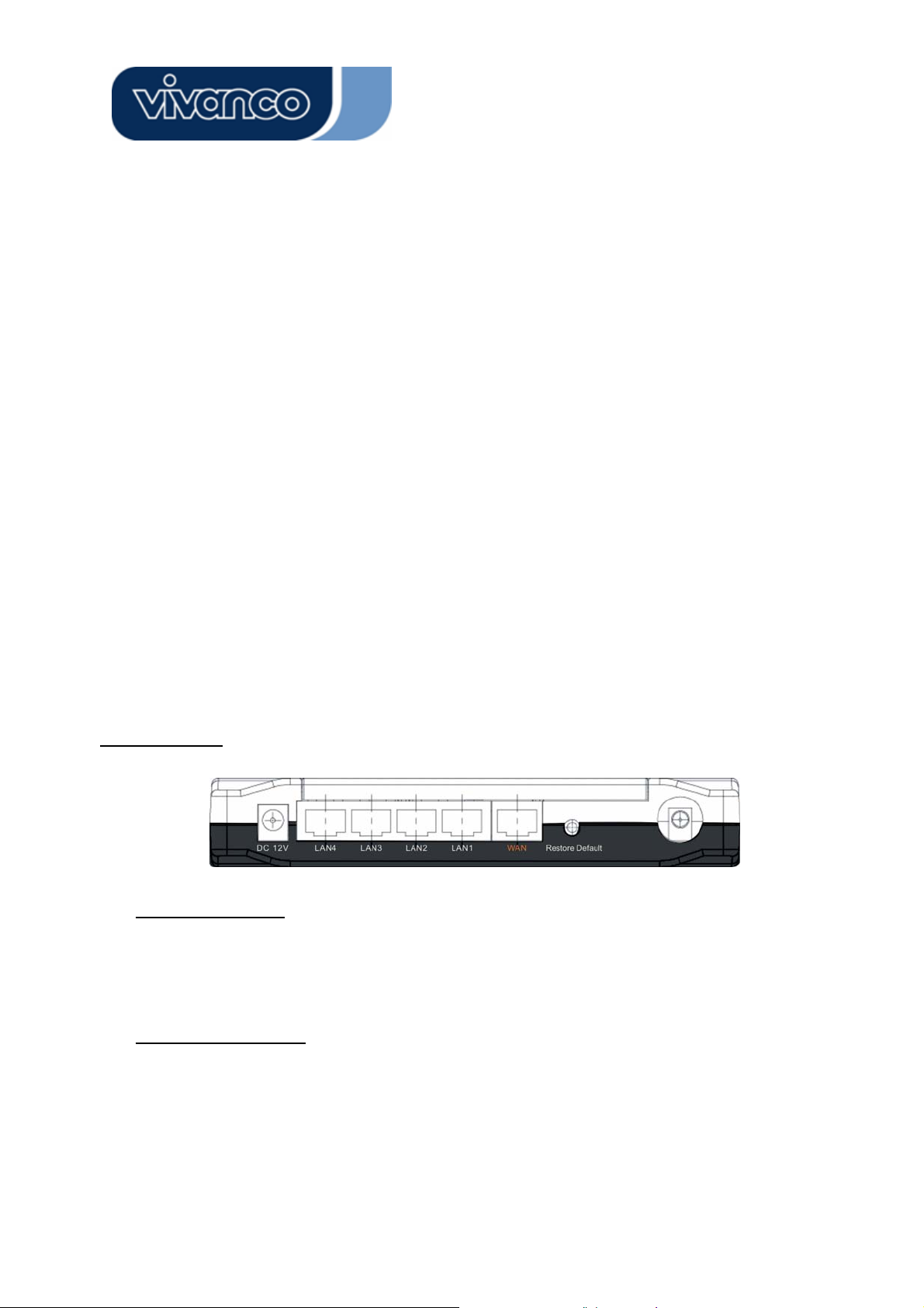
The Rear Panel
Power Connection
Plug the circle end of the power adapter firmly into the rear panel of the Wireless Router,
and the other end put into an electric service outlet th
Pl
acement (Optional)
There are three ways to place the Router. The first way is to place the Router horizontally
the Router vertically on a surface. These options are explained in further detail below.
en the system is ready.
ndon a surface. The second way is to attach the router to the wall. The third way is to sta
6
Page 7

23414 WLAN ROUT 54-N
Desktop Option
1. The Router has one plastic stand that can be divided into two parts.
2. Combine one part of stand with the side of router.
3. Do the same with the second part.
4. Place the Router
Wall-mount option
Before attach this router on the wall, you have to finish the desktop option steps first.
1. Select a location with access for cables and a power outlet.
2. flat surface and mark the two holes for
Unplug the unit. Place it upside down on a
anchors.
3. Installing the Wall mount anchor (p
mer.
4. Insert the provided screws in each hole of the stand parts.
5. Attaches the unit to the anchors on the wall.
S
tand Option
1. The Router includes two
2.
Combine two parts into one stand. Combine it with the side of router near the power
port. Push the stand up to snap it into place.
3. Place the Router.
Res
tore Default Button
1. Push the button for more than 5 seconds and then release it, the system will return to
factory default setting. In the meantime, system rewrites flash to default value and Status
LED halts for a while. Approximately 60 seconds later, the Status LED blinks green periodically, now th
e whole system parameters have returned to factory default value. If the
stand parts.
lastic) into the wall with tools such as drill or ham-
process has been interrupted by any reason (power off…), the system will fail. Before
performing the process, ensure a safe operating environment please.
2. To reboot the Router, Press the button for 2-5 seconds and then release it, and all the
setting won’t be erased. Wait for the Router to complete the reboot, and then you can
start to use it.
7
Page 8

23414 WLAN ROUT 54-N
Warning! Incomplete factory setting recovery he Wireless Router mal-
fu in this situation, do not try to repair it by yourself. Consult your
nction. If you are unfortunately
lo
cal distributor for help.
procedure will cause t
INSTALLING AND USING WIRELESS ROUTER
This on and configuration of the Wireless
Chapter provides a step-by-step guide to the installati
Router
. We suggest you go over the whole chapter and then do more advanced operation.
N
etwork configuration setup
ps to build up the network:
Ste
Connect the ADSL
¾ or Cable modem to the Ethernet WAN port on the back of the Wireless
Router by using the UTP cable.
¾ Connect the phone line from the wall socket to the line-in port on the ADSL modem, or the
coaxial cable to the line-in port on the Cable modem.
¾ Plug-in the power adapter to the modem and turn on the power. Install the Ethernet card into
the computer by referring to the User Guide that came with the card.
¾ Connect the computer to the Wireless Router by using standard twisted-pair Ethernet cable
from the computer’s Ethernet card to an 10/100Mbps Ethernet port on the back of the
Wireless Router.
¾ Plug-in the power adapter to the Router and the other side to the wall outlet.
8
Page 9
23414 WLAN ROUT 54-N
Computer configuration setup
In order to communicate with this Wireless Router, you have to configure the IP addresses of
your computer to be compatible with the device. The router supports DHCP server and it is
enabled as default. Users that configure your IP address as “Obtain an IP address
automatically” may skip the following IP configuration instruction.
Note:
1. The default network setting of the device:
IP address: 192.168.1.1
Subnet Mask: 255.255.255.0
DHCP Server: enabled
2. In the following TCP/IP configuration guide, the IP address “192.168.1.2 ” is assumed to
be your IP address if you want to specify IP addresses manually. Please DO NOT choose
192.168.1.1 for the IP address (192.168.1.1) has been set as the default IP for this de-
vice.
3. The following TCP/IP configuration guide uses windows XP as the presumed operation
system.
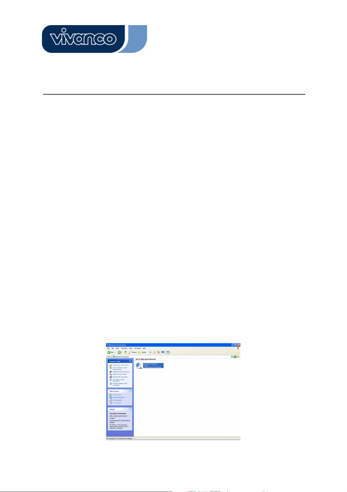
Procedures to configure IP addresses for your computer
1. If you are in Classic Start menu view, click Start > Settings > Control Panel > Network
Connections.
2. If you are in Start menu view, click Start > Control Panel > Network Connections.
3. Double click “Local Area Connection”
9
Page 10
23414 WLAN ROUT 54-N
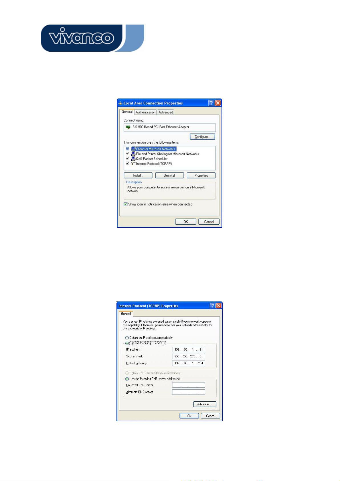
4. Choose Internet Protocol (TCP/IP) and click Properties.
5. You may choose “Obtain an IP address automatically”(recommend) to get IP address
automatically or choose “Use the following IP address” to specify IP addresses manually.
Please click the OK button after your configuration.
10
Page 11
23414 WLAN ROUT 54-N
MANAGEMENT
Wireless Router configuration setup
In order to make the whole network operate successfully, it is necessary to configure the
Wireless Router through your computer has a WEB browser installed. Please follow up the
steps listed below.
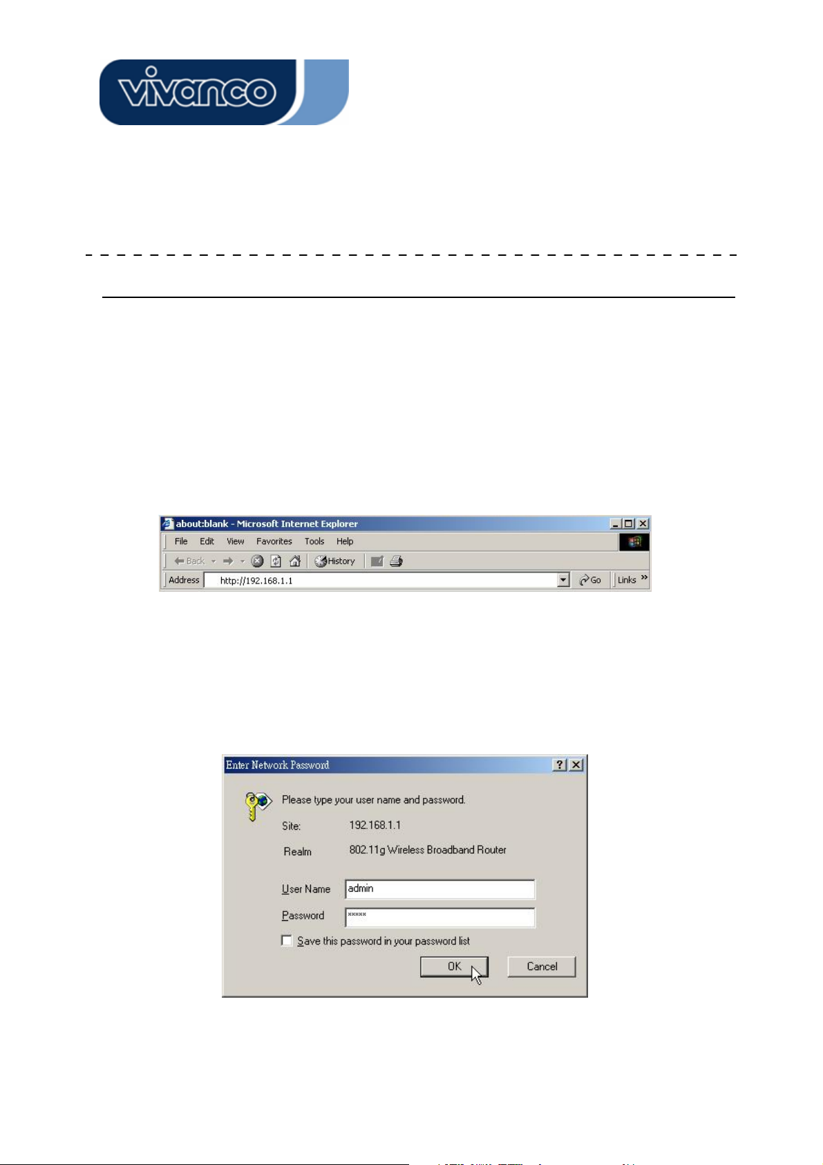
1. Double click the Internet WEB browser icon on your desktop screen (Netscape
Communicator 4.0 and Internet Explorer 3.0 or update version)
2. Type 192.168.1.1 into the URL WEB address location and press Enter.
3. The Username and Password Required window appears.
- Enter admin in the User Name location (default value).
- Enter admin in the Password location (default value).
- Click “OK” button
11
Page 12
23414 WLAN ROUT 54-N
4. The Graphic User Interface
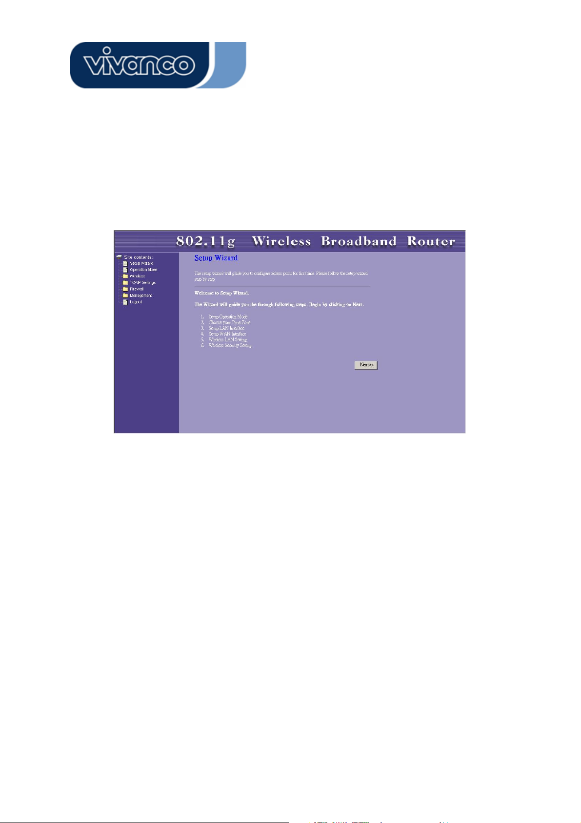
After the password authorization, the Setup Wizard shows up as the home page of the
Graphic User interface. You may click on each folder on left column of each page to get
access to each configuration page.
12
Page 13
23414 WLAN ROUT 54-N
Setup Wizard
If you are using the router for the first time, you may follow the procedures of the setup wizard
to do a step-by-step configuration.
Note: The following instruction does an overall introduction to the Setup Wizard. For detail in-
formation to each item, please refer to instruction of each page.
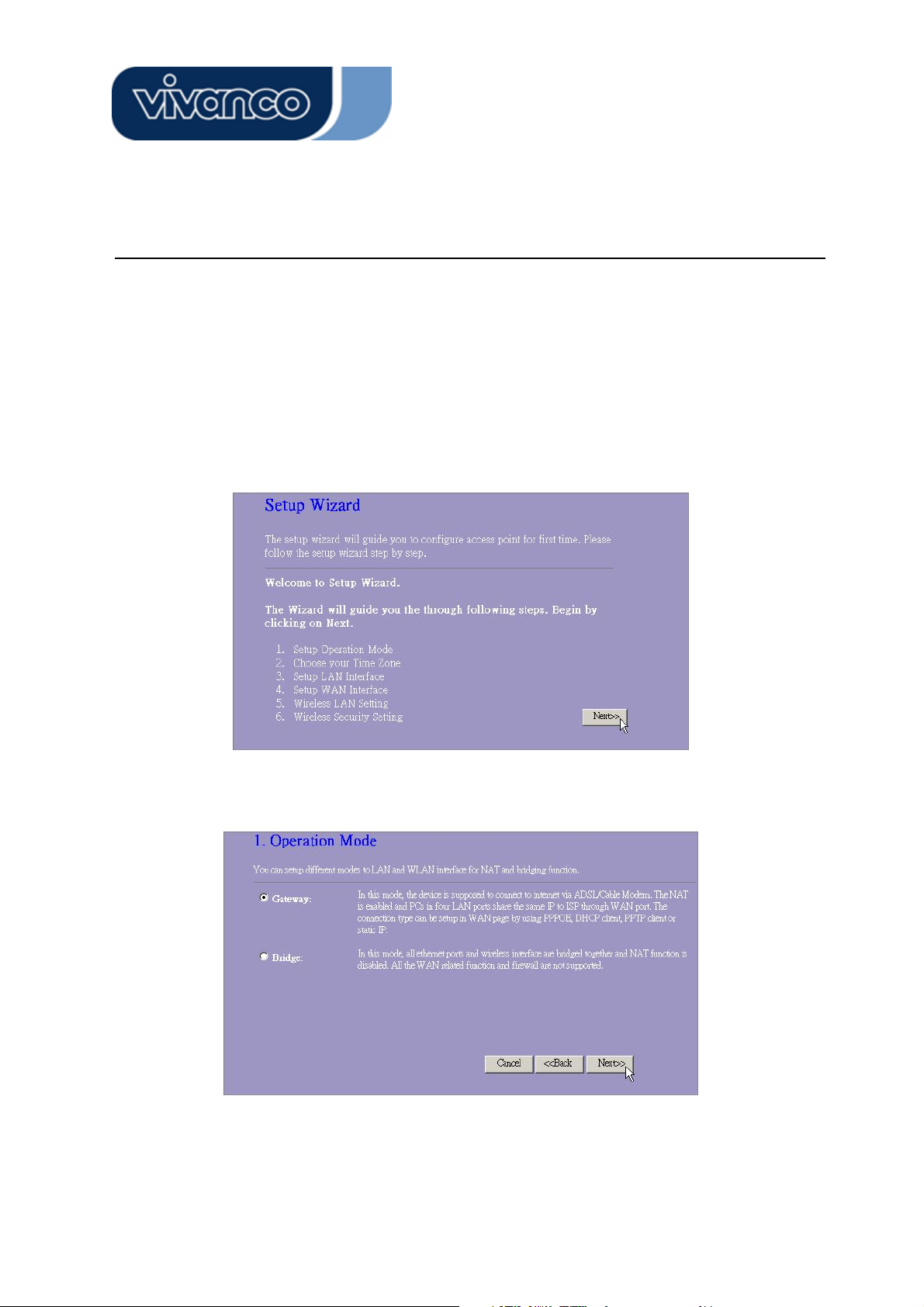
1. To start the Setup Wizard, click the “Next” button to proceed.
2. Select your demanding operation mode and click “Next”.
13
Page 14
23414 WLAN ROUT 54-N
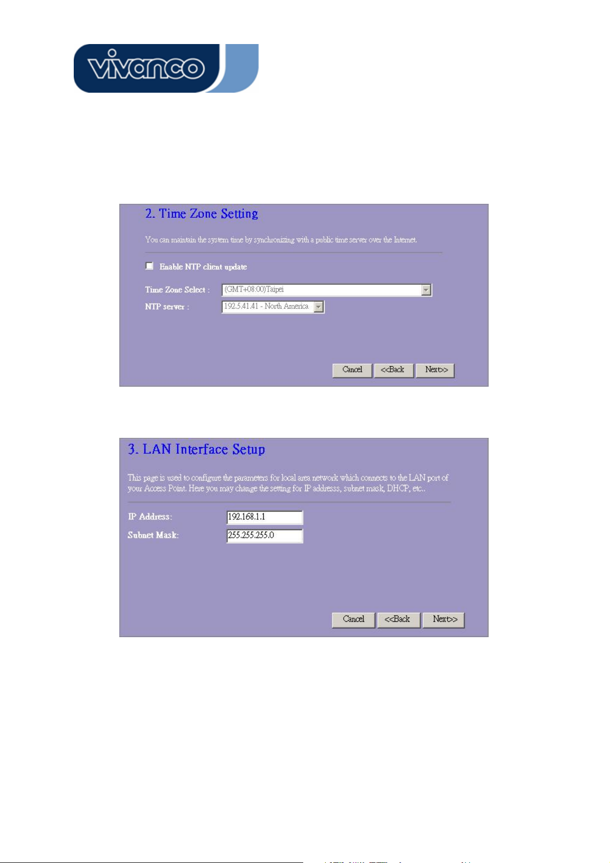
3. Mark the check box to enable synchronizing time by NTP server. Select the religion you live
and a NTP server by clicking the drop list then click “Next”.
4. Specify an IP address and subnet mask for connecting to the router in LAN.
14
Page 15
23414 WLAN ROUT 54-N
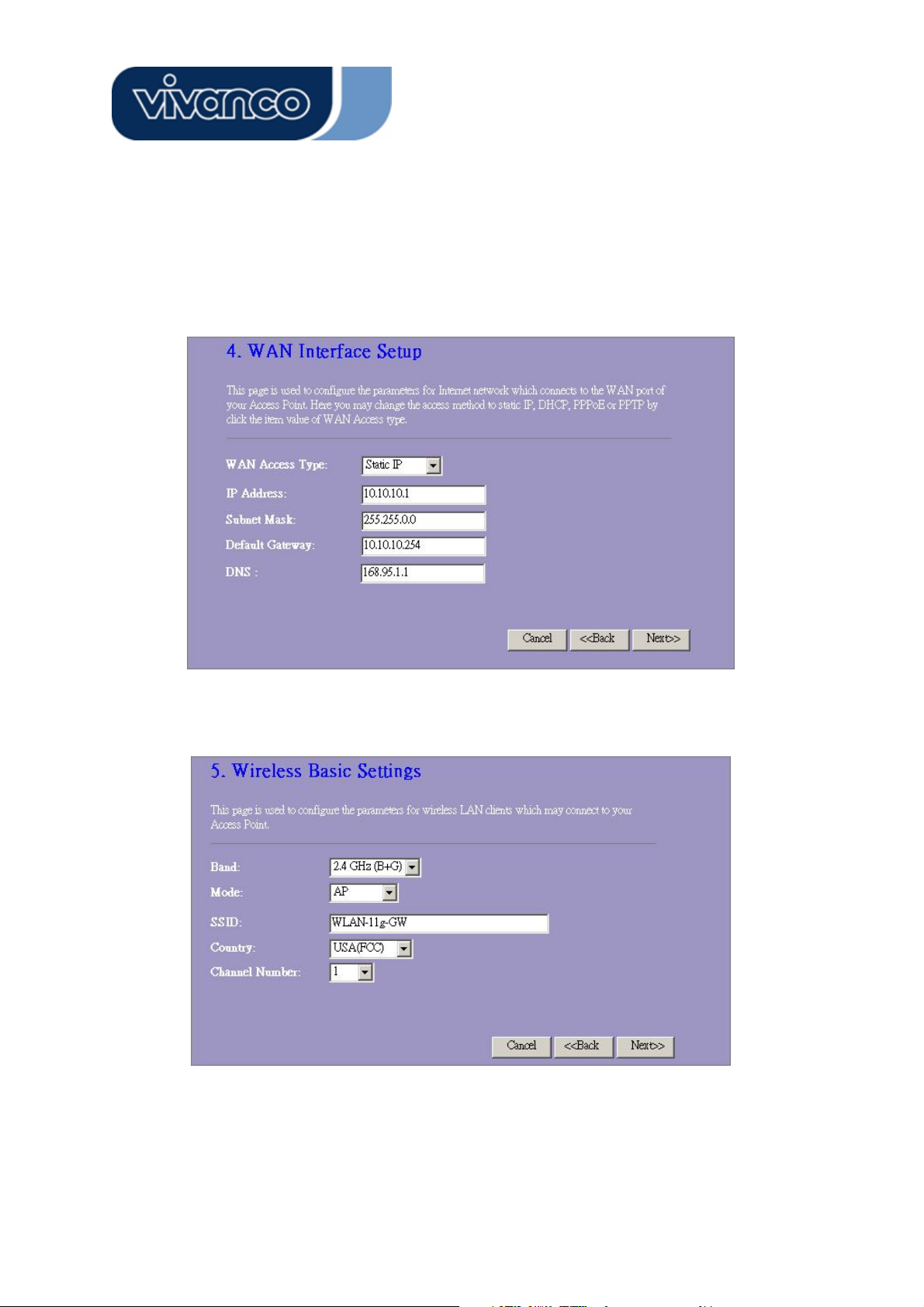
5. Select a WAN access type for the router to connect to Internet. Fill in the parameters that
required in each blank, and then click the “Next” button. You may get those parameters from
your ISP.
6. Select the wireless parameters that are used for associating with this router and click Next.
15
Page 16
23414 WLAN ROUT 54-N
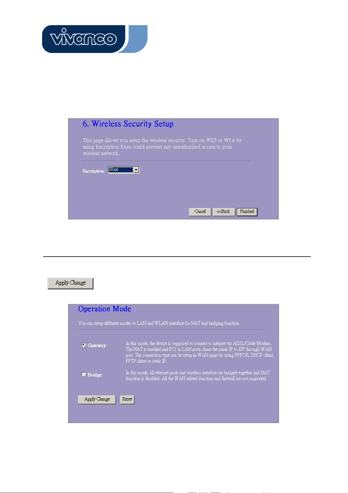
7. Click the drop list to select the encryption type for your wireless network. Fill in the parameters for the encryption type you select and click finish to complete configuration.
Operation Mode
To select an operation mode for this router, click on the mode that you want to perform and click
the
button to execute.
16
Page 17

23414 WLAN ROUT 54-N
Wireless
Wireless Access Point builds a wireless LAN and can let all PCs equipped with
IEEE802.11b/g wireless network adaptor connect to your Intranet. It supports WEP encryption and MAC address filter to enhance the security of your wireless network.
Basic Settings
You can set up the configuration of your Wireless and monitor the Wireless Clients associate
with your AP.
Configuration
Disable Wireless LAN Interface
Band
Mode
SSID
Country
Channel Number
Associated Clients
Enable Universal
Repeater Mode
SSID of Extended
Interface
Click <Apply changes> button at the bottom of the screen to save the above configurations.
You can now configure other advance sections or start using the router (with the advance set-
To Disable interface of Wireless LAN
To select a band for this device to match
802.11b, 802.11g or both.
Configure this device as AP, WDS or both.
The name of the wireless network
Select the region you live.
The channel used by the wireless LAN. All
devices in the same wireless LAN should use
the same channel.
Click "Show Active Clients" button, then an
"Active Wireless Client Table" will pop up. You
can see the status of all active wireless stations
that are connecting to the access point.
Mark this checkbox to enable Universal
Repeater Mode which acts this device as an AP
and client simultaneously.
While you enable the Universal Repeater Mode,
you have to specify an SSID for the extended
interface.
tings in place)
17
Page 18
23414 WLAN ROUT 54-N
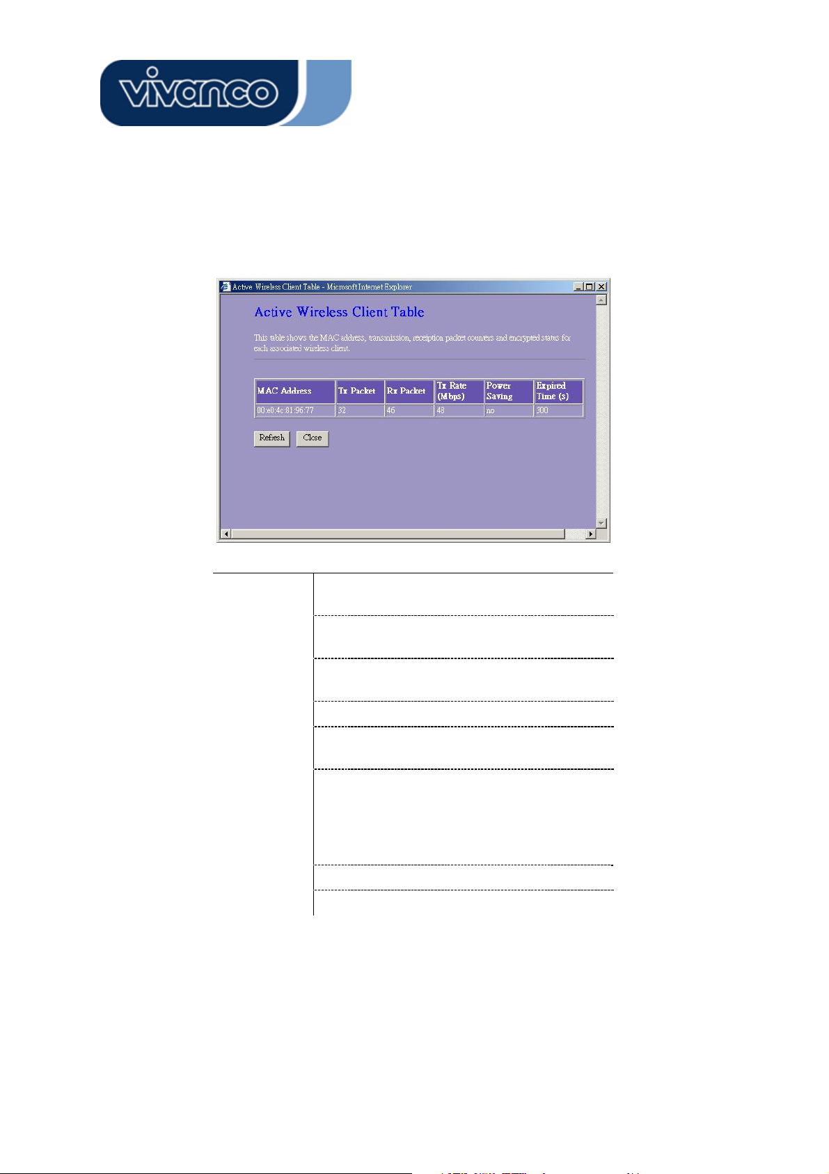
x Active Wireless Client Table
This is the window that pops up after clicking the “Show Active Clients” button.
MAC
Address
Tx Packet
Rx Packet
TX Rate
Power
Saving
Expired Time
Refresh
Close
MAC address of this active wireless station.
The number of transmitted packets that are
sent out from this active wireless station.
The number of received packets that are
received by this active wireless station.
The transmission rate
Shows if the wireless client is in Power
Saving mode
This is the time in second before
dissociation. If the wireless keeps idle longer
than the expired time, this wireless router
will dissociate it. The wireless client station
has to associate again when it is active.
Refresh the "Active Wireless Client Table".
Close the "Active Wireless Client Table".
18
Page 19
23414 WLAN ROUT 54-N
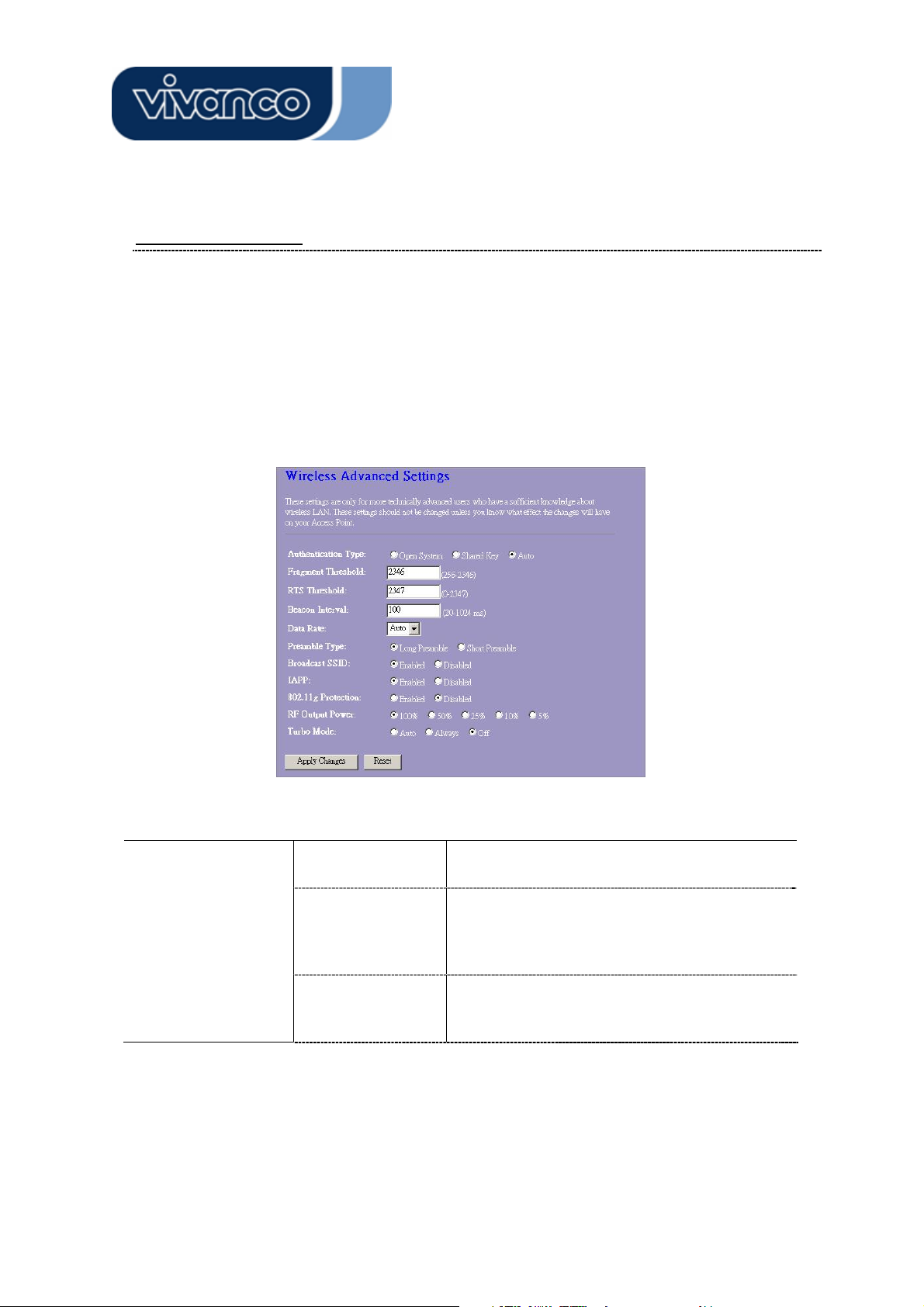
Advanced Settings
You can set advanced wireless LAN parameters of this router. The parameters
include Authentication Type, Fragment Threshold, RTS Threshold, Beacon Interval,
Data Rate, Preamble Type, Broadcast SSID, IAPP and 802.11g Protection. We
recommend not changing these parameters unless you know what changes will be
there on this router.
Configuration
Authentication Type
Open System
mode
Shared Key mode
Auto
Wireless AP can associate with this wireless
router without WEP encryption.
You should also setup WEP key in the
"Security" page and wireless AP associating
with this wireless router should use WEP
encryption in the authentication phase.
The wireless client can associate with this
wireless router by using any one of these two
Modes.
19
Page 20
23414 WLAN ROUT 54-N
Fragment Threshold
RTS Threshold
Beacon Interval
Data Rate
Preamble Type
Broadcast SSID
IAPP
To specifies the maximum size of packet during the data
transition. The lower values you set, the worst performance
it will be.
If the packet size is smaller the RTS threshold, the wireless
router will not send this packet by using the RTS/CTS
mechanism.
The period of time how long a beacon is broadcasted.
The "Data Rate" is the data packets limitation this wireless
router can transmit. The wireless router will use the highest
possible selected transmission rate to transmit the data
packets.
It defines the length of CRC block in the frames during the
wireless communication. "Short Preamble" is suitable for
heavy traffic wireless network. "Long Preamble" provides
much communication reliability
If you enable "Broadcast SSID", every wireless station located within the coverage of this wireless router can discover this wireless router easily. If you are building a public
wireless network, enabling this feature is recommended.
Disabling "Broadcast SSID" can provide better security.
To enables multiple AP to communicate and pass information regarding the location of associated Stations.
Some 802.11g wireless adapters support 802.11g protec-
802.11g Protection
RF Output power
Turbo Mode
Click the <Apply Changes> button at the bottom of the screen to save the above configura-
tions. You can now configure other advance sections or start using the router.
tion, which allows the adapters searches for 802.11g singles
only. Select the “Disabled” to disable supporting 802.11g
protection or select “enable” to support this function.
Select the RF (Radio Frequency) power. The RF output
power has positive correlation with signal strength.
Some of our wireless adapters supports turbo mode, which
provides a better connection quality. Select “Always” to
support turbo mode or select “off” to turn it off . Select “Auto”
turns it on or off automatically.
20
Page 21
23414 WLAN ROUT 54-N
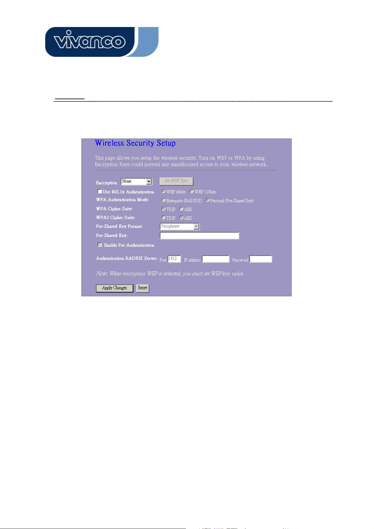
Security
At the page, you can set up the WEP, WPA Encryption to ensure the security of your
Wireless.
21
Page 22

23414 WLAN ROUT 54-N
Configuration
Encryption
Use 802.1x Authentication
WPA Authentication Mode
WPA Cipher Suite
WPA2 Cipher Suite
Pre-Shared key Format
Pre-shared Key
Enable Pre-Authentication
To enable WEP, WPA, WPA2 and WPA2
Mixed encryption modes, select the option in
the drop list. If you select none, any data will
be transmitted without Encryption and any
station can access the router.
To enable the 802.1x, Click the check box of
the item.
There are two items, “Enterprise
(WPA-Radius)” and “Personal (Pre-Shared
Key)”. You can select the mode by clicking
the item.
Select the WPA Cipher Suite to be TKIP or
AES
Select the WPA2 Cipher Suite to be TKIP or
AES
To decide the format, select what you need in
the drop list.
Enter the Pre-shared Key according to the
pre-shared key format you select.
You can mark this checkbox to enable
Pre-authentication after selecting Enterprise
(RADIUS) WPA 2 authentication mode
Authentication RADIUS Sever
Click <Apply Change> at the bottom of the screen to save the above configurations. You
can now configure other advance sections or start using the router.
If you use RADIUS Sever to ensure your
security, you have to set up the parameters in
the item. To set up the Port, IP address and
Password of your RADIUS, Enter the Port
Number, IP and Password.
22
Page 23
23414 WLAN ROUT 54-N
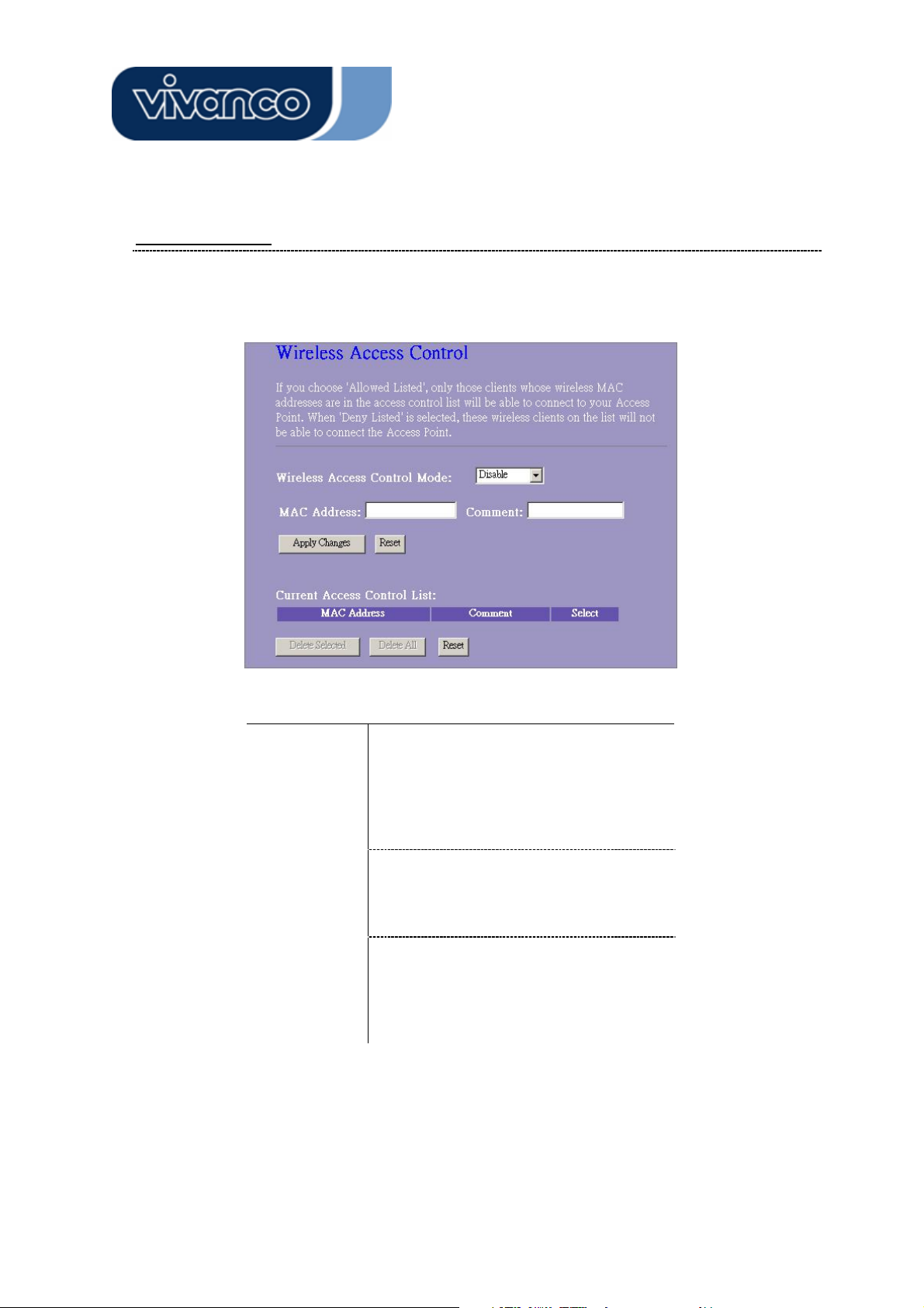
Access Control
To restrict the Number of Access authentication of Stations, Set up the control list in
this page.
Configuration
Wireless
Access
Control Mode
MAC Address
& Comment
Current
Access
Control list
Click <Apply Change> button to save the above configurations. You can now
configure other advance sections or start using the router.
Click on the drop list to choose the
access control mode. You may select
“Allow listed” to allow those allowed
MAC addresses or select “Deny Listed”
to ban those MAC addresses from
accessing to this device.
To set up the Value of MAC Address &
Comment; enter the MAC Address and
Comment of station and click Apply
Changes to save.
To Delete the station on the list, Click the
check box in the select item and click the
“Delete Selected”. If you want to delete
all stations on the list, click “Delete All” to
remove all of them.
23
Page 24
23414 WLAN ROUT 54-N
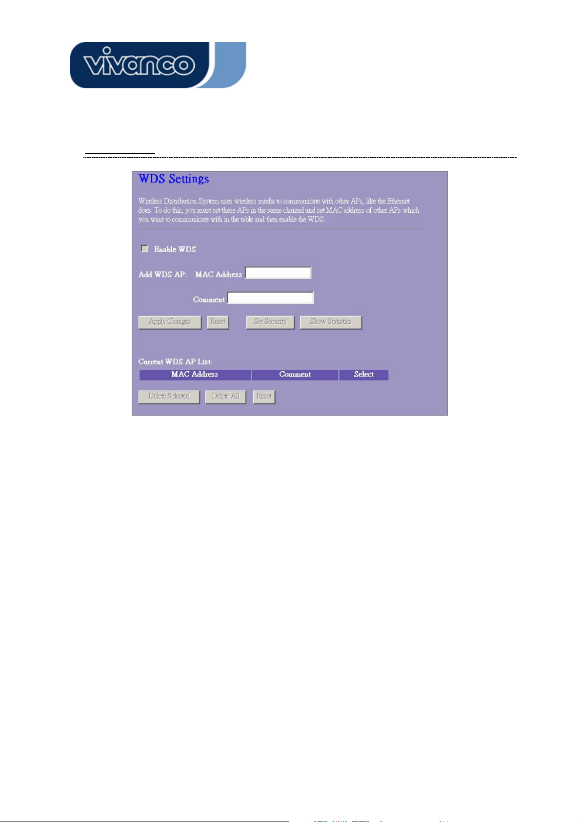
WDS Setting
Wireless Distribution System allows the router to communicate with other APs
wirelessly. To make it work, you must ensure that these APs and the Router are in
the same Channel and add these APs MAC Address and Comment values into the
WDS list. Don’t Forget to Enable the WDS by click the check box of “Enable WDS”
and press “Apply Changes” button to save.
To Delete the AP on the list, Click the check box in the select item and click the
“Delete Selected”. If you want to delete all APs on the list, click “Delete All” to
remove all of them.
24
Page 25
23414 WLAN ROUT 54-N
TCP/IP Setting
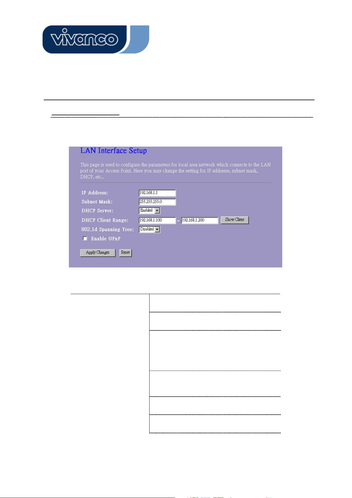
LAN Interface Setup
To set up the configuration of LAN interface, Private IP of you router LAN Port and
Subnet mask for your LAN segment.
Configuration
IP address
Subnet Mask
DHCP Server
DHCP Client Range
802.1d Spanning tree
Enable UPnP
The IP of your Router LAN port (Default
192.168.1.1)
Subnet Mask of you LAN (Default
255.255.255.0)
To give your LAN Client an IP, you have to
enable “DHCP Server”. If not, manual setting
up your client IP is necessary when you want
to use the router as your client’s default
gateway.
Specify the DHCP Client IP address range.
You can also click the “Show Client” button to
listed those connected DHCP clients.
To prevent from network loops and preserve
the quality of bridged network
Mark this checkbox to allow this router to be
recognized by UPnP.
25
Page 26
23414 WLAN ROUT 54-N
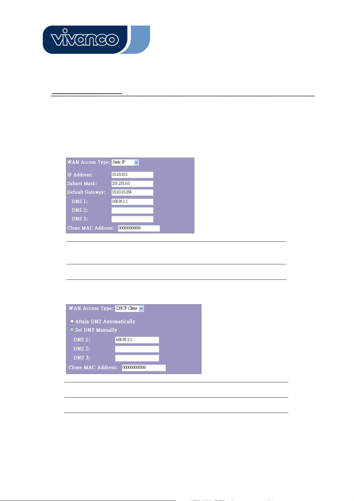
WAN Interface Setup
This page allows users to configure those parameters for connecting to Internet. You
may select the WAN Access Type from the drop list and configure parameters for each
mode.
Static IP Mode
IP Address, Subnet Mask and
Default Gateway
DNS 1, 2 and 3
DHCP Client Mode
Attain DNS automatically
Set DNS Manually
Fill in the IP address, Subnet Mask and
Default Gateway that provided by your
ISP.
To specify the DNS, and enter the DNS
provided by your ISP in DNS 1 2 3.
If your DNS provide by ISP is dynamic,
choose “Attain DNS automatically
To specify the DNS, and enter the DNS
provided by your ISP in DNS 1 2 3.
26
Page 27
23414 WLAN ROUT 54-N
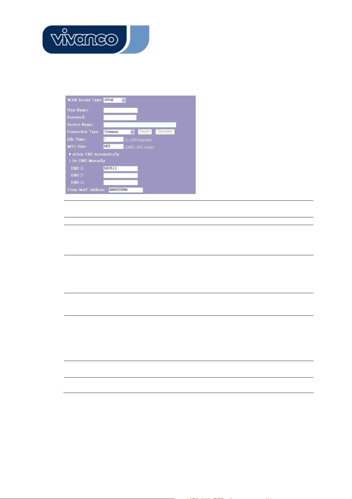
PPPoE Mode
, password and User Name
service name
Connection Type
Idle Time:
MTU Size
Attain DNS automatically:
Set DNS Manually
Fill in the User Name, password and service name that
provided by your ISP.
ous” is for Always keep connection“Continu
“Connect on demand” is for bill by connection time. Y
can set up the Idle time for the value specifies the numbe
of time that elapses before the system automatically
disconnects the PPPoE session.
anual” To connect to ISP, click “Connect” manual
“M ly
from the WEB user interface. The WAN connection will
not disconnected due to the idle timeout. If the WAN
breaks down and latter links a
auto-connect to the ISP.
The value specifies the number of idle time that elapses
before the system automatically disconnects the PPPoE
session.
To Enable the Maximum Transmission Unit of Router
setup. Any packet over this number will be chopped up
into suitable size before sending. Larger number will
enhance the transmission performance.
Enter your MTU number in the text-box to set the
limitation.
gain, the router will not
ou
line
If your DNS provide by ISP is dynamic, choose
“Attain DNS automatically
To specify the DNS, and enter the DNS provided by your
ISP in DNS 1 2 3.
r
27
Page 28
23414 WLAN ROUT 54-N
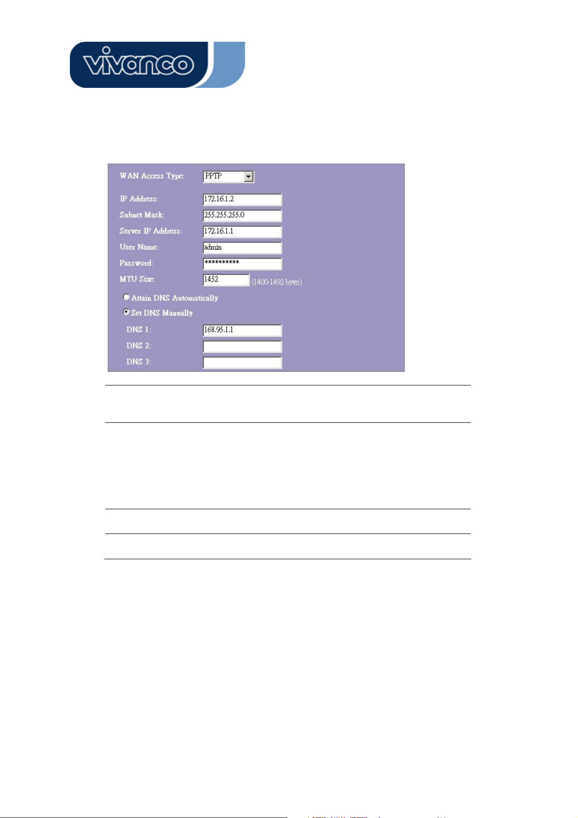
PPTP Mode
IP Address, Subnet Mask,
Server IP Address, User
Name and Password
MTU Size
Attain DNS automatically
Set DNS Manually
Fill in the IP address, Subnet Mask, Server IP
Address, User Name and password that
provided by your ISP.
To Enable the Maximum Transmission Unit of
Router setup. Any packet over this number will
be chopped up into suitable size before
sending. Larger number will enhance the
transmission performance.
Enter your MTU number in the text-box to set
the limitation.
If your DNS provide by ISP is dynamic, choose
“Attain DNS automatically
To specify the DNS, and enter the DNS provided
by your ISP in DNS 1 2 3.
28
Page 29
23414 WLAN ROUT 54-N
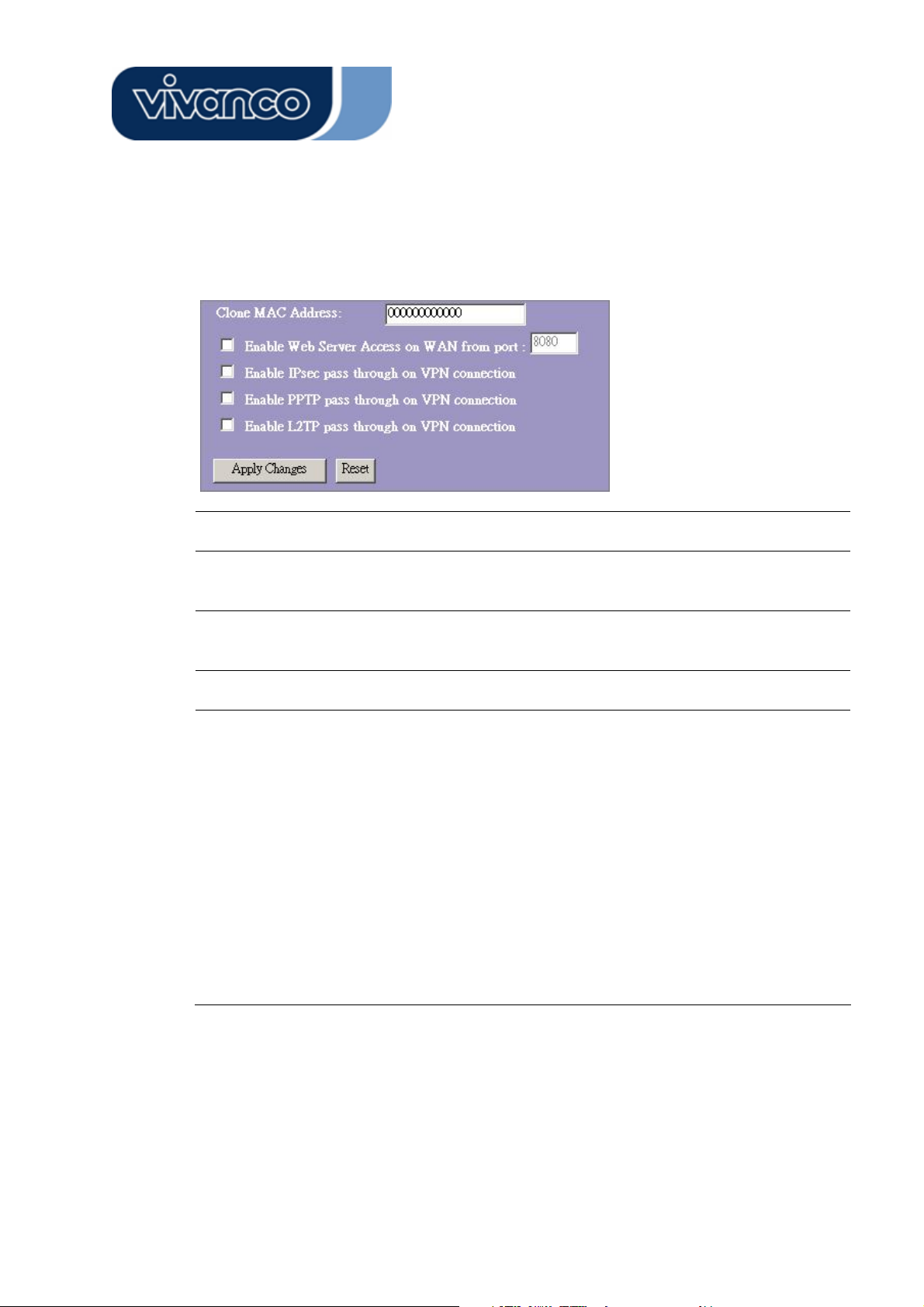
Common configurations for WAN interface
There are some settings are able to be configured on each WAN access types:
Enable Web Server Access on
WAN from port
Enable IPsec pass through on
VPN connection
Enable PPTP pass through on
VPN connection
Enable L2TP pass through on
VPN connection
Clone MAC Address
To Enable the user to access this Router through
Internet, Enter the specific IP and the port number
Mark the check box to enable IPsec pass through
on VPN connection and clear the checkbox to
disable.
Mark the check box to enable PPTP pass through
on VPN connection and clear the checkbox to
disable.
Mark the check box to enable L2TP pass through on
VPN connection and clear the checkbox to disable.
When ISP use MAC address authentication (with
DHCP), then the MAC address of the Ethernet card
attached to your Cable modem must be registered
with the ISP before connecting to the WAN
(Internet). If the Ethernet card is changed, the new
MAC address must be registered with the ISP.
MAC cloning feature allows t
reported by WAN side network interface card to be
set to the MAC address already registered with the
ISP eliminating the need to register the new MAC
address with the ISP. This feature does not change
the actual MAC address on the NIC, but instead
changes the MAC address reported by Wireless
Router to client requests. To Change the MAC
address, enter it in the text box.
he MAC address
29
Page 30
23414 WLAN ROUT 54-N
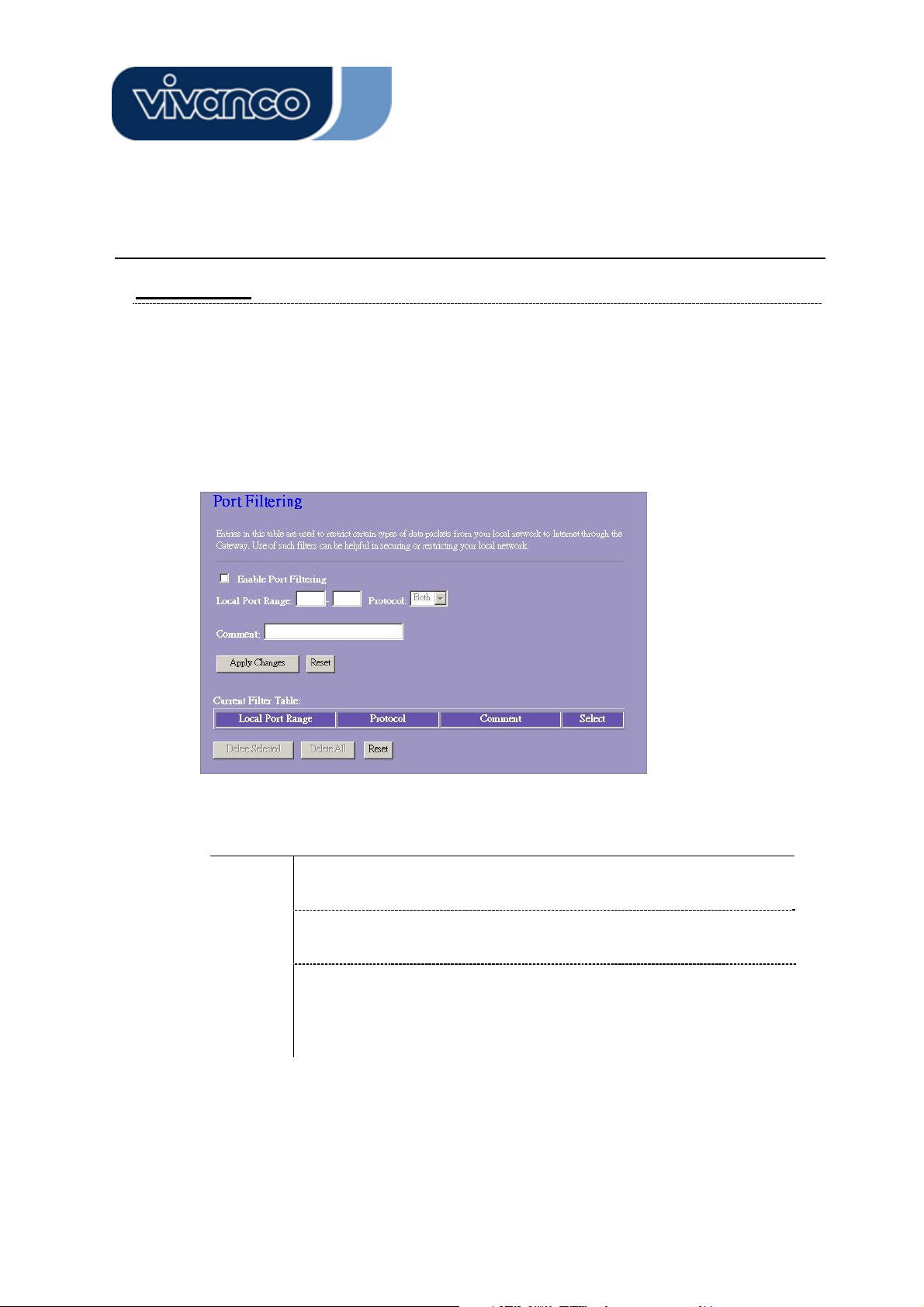
Firewall Configuration
Port Filtering
The firewall could not only obstruct outside intruders from intruding your system, but
also restricting the LAN users.
Port Filtering To restrict certain type of data packets from your LAN to Internet
through the Router, add them on the Current Filtering Table.
Configuration
STEPS
Click <Apply Change> at the bottom of the screen to save the above configurations. You can now configure other advance sections or start using the
router.
1. Click the check box of “Enable Port Filtering” to enable the
function.
2. Enter the Port range (EX 25-110), Protocol (UDP/TCP), and
comment (EX. E-Mail)
3. To Delete the Port range on the list, Click the check box in the
select item and click the “Delete Selected”. If you want to
delete all entries on the list, click “Delete All” to remove all of
them.
30
Page 31

23414 WLAN ROUT 54-N
IP filtering
The Wireless Router could filter the outgoing packets for security or management
consideration. You can set up the filter against the IP addresses to block specific
internal users from accessing the Internet.
Configuration
STEPS
Click <Apply Change> at the bottom of the screen to save the above configurations.
You can now configure other advance sections or start using the router.
1. Click the check box of “Enable IP Filtering” to enable the function.
2. Enter the specific Local IP address (EX 10.10.3.9), Protocol
(UDP/TCP), and comment (EX. Peter)
3. To Delete the IP address on the list, Click the check box in the select
item and click the “Delete Selected”. If you want to delete all entries on
the list, click “Delete All” to remove all of them.
31
Page 32

23414 WLAN ROUT 54-N
MAC filtering
The Wireless Router could filter the outgoing packets for security or management
consideration. You can set up the filter against the MAC addresses to block specific
internal users from accessing the Internet.
Configuration
STEPS
Click <Apply Change> at the bottom of the screen to save the above configurations.
You can now configure other advance sections or start using the router.
1. Click the check box of “Enable MAC Filtering” to enable the function.
2. Enter the specific MAC address (EX 00:0e:b6:a8:72), and comment
(EX. Peter)
3. To Delete the MAC address on the list, Click the check box in the
select item and click the “Delete Selected”. If you want to delete all
Entries on the list, click “Delete All” to remove all of them.
32
Page 33

23414 WLAN ROUT 54-N
Port forwarding
The Port Forwarding allows you to re-direct a particular range of service port
numbers (from the Internet/WAN Ports) to a particular
LAN IP address. It helps you to host some servers behind the router NAT firewall.
Configuration
STEPS
Click <Apply Change> at the bottom of the screen to save the above configurations.
1. Click the check box of “Enable port forwarding” to enable the
function.
2. Enter the specific IP address (EX 10.10.10.10), Protocol
(UDP/TCP), Port range (EX 25-110), and comment (EX. E-Mail)
3. To Delete the IP address on the table, Click the check box in the
select item and click the “Delete Selected”. If you want to delete all
Entries on the table, click “Delete All” to remove all of them.
33
Page 34

23414 WLAN ROUT 54-N
URL Filtering
The URL Filter allows users to prevent certain URL from accessing by users in LAN.
This filter will block those URLs that contain certain keywords.
Configuration
STEPS
Click <Apply Change> at the bottom of the screen to save the above configurations.
1. Click the check box of “Enable URL Filtering” to enable the function.
2. Enter the URL that is going to be banned.
3. To Delete the URL on the table, Click the check box in the select
item and click the “Delete Selected”. If you want to delete all URLs
on the table, click “Delete All” to remove all of them.
34
Page 35

23414 WLAN ROUT 54-N
Virtual DMZ
The virtual DMZ is used to enable protocols, which need to open ports on the router.
The router will forward all unspecified incoming traffic to the host specified in this
page.
To configure it, enter the Host IP (private IP address) and Click “Apply changes” to
enact the setting.
35
Page 36

23414 WLAN ROUT 54-N
Management
Status
In the home page of the Wireless Router, the left navigation bar shows the options to
configure the system. In the right navigation screen is the summary of system status
for viewing the configurations.
36
Page 37

23414 WLAN ROUT 54-N
z System
Uptime
Firmware Version
z Wireless Configuration
Mode
Band
SSID
Channel Number
Encryption
BSSID
Associated Clients
z LAN Configuration
IP Address
The period that you power the device on.
The version of the firmware applied on this device.
The operation mode of the wireless router
The performing band of this wireless router
The name of this wireless network
The channel used by the wireless LAN. All devices in the
same wireless LAN should user the same channel
The security encryption status of this wireless network
The Basic Service Set Identity of this router.(This
parameter is the same as the MAC address of LAN port)
The number of associated clients.
IP Address of router
Subnet Mask
DHCP Server
MAC Address
z WAN Configuration
Attain IP Protocol
IP Address
Subnet Mask
Default Gateway
MAC Address
Subnet Mask of the router
Enabled or Disable of DHCP
MAC Address of LAN-port
Static IP address
IP address of WAN-port
Subnet Mask of WAN-port
Default Gateway of WAN-port
MAC Address of WAN-port
37
Page 38

23414 WLAN ROUT 54-N
Statistics
On this page, you can monitor the sent & received packets counters of wireless, Ethernet
LAN, and Ethernet WAN. To see the latest report, click refresh button.
DDNS
This page allows users to connect to DDNS. To enable DDNS, Mark the “Enable DDNS”
checkbox. Select the service provider from the drop list. Fill in domain name, username,
and password. Click the “Apply Change” button after configuration.
38
Page 39

23414 WLAN ROUT 54-N
Time Zone Setting
This page allows users to configure the time of the router. To specify manually, fill in the
blanks in “Current Time” and click the “Apply Change” button. To synchronize time from a
timeserver, please mark the “Enable NTP client update” checkbox, select a NTP server
from the drop list or manually enter a NTP server. Click the “Apply Change” button after
your configuration.
mLogSyste
This System Log page shows the information of the current activities on the router.
To enable system log function:
1. Mark the “Enable Log” c
2. To see all information of the system, select the “system all” checkbox.
To see wireless information only, select the “wireless” checkbox.
To sent the log information to a certain note, select the “Enable Remote Log” checkbox
and fill in the IP address in the “Log Server IP Address” box.
3. Click the “Apply Changes” button to activate
You could also click the “Refresh” button to refresh the log information or click the “clear”
button to clean the log table.
heckbox.
39
Page 40

23414 WLAN ROUT 54-N
Upgrade Firmware
To Upgrade Firmware,
STEPS
1. Click “browse…” button to select the firmware
you want to upgrade.
2. Click Upload to start the upgrade process.
Please don’t close the WEB-browser and wait
for process to complete. When Upgrade is
completed, you can start to use the router.
40
Page 41

23414 WLAN ROUT 54-N
Save and Reload Settings
To save setting to file, click “Save...” button.
To load setting from file,
1. Click “Browse…” on the to select the file
2. Click upload to start the process and wait for it to complete
To reset setting to Default, click reset to start the process and it will be completed till
the status LED start blinking.
Password
To set up the Administrator Account information, enter the Username, New password, and
reenter the password on the text box. Don’t forget to click the “Apply Changes” to save the
configuration.
41
Page 42

23414 WLAN ROUT 54-N
PRODUCT SPECIFICATIONS
IEEE802.3, 10BASE-T
IEEE802.3u, 100BASE-TX
Standard
Interface
WAN Connection
Cable Connections
Network Data Rate
Transmission Mode
LED indications
Security
Receiver Sensitivity
Memory
IEEE802.3x full duplex operation and flow control
IEEE802.11b wireless LAN infrastructure
IEEE802.11g wireless LAN infrastructure
1 * WAN port
4 * 10/100 RJ-45 Fast Ethernet switching ports
Antenna: 802.11b/g wireless reverse SMA detachable
Ethernet 10/100 Mbps
RJ-45 (10BASE-T): Category 3,4,5 UTP
RJ-45 (100BASE-TX): Category 5 UTP
802.11b: 1, 2, 5.5 and 11Mbps
802.11g: 6, 9, 12, 18, 24, 36, 48, and 54Mbps
Auto-Negotiation (Full-duplex, Half-duplex)
System: Power, Status
Port (WAN): ACT/LINK
Port (LAN): ACT/LINK
Port (Wireless): ACT
64/128-bit WEP,
WPA (TKIP with IEEE 802.1x), WPA2, AES
54Mbps OFDM, 10%PER, -71dBm
11Mbps CCK, 10%PER, -81dBm
1Mbps BPSK, 10%PER, -92dBm
Flash: 2MB NOR type, SDRAM: 8MB
Transmit Power
Range Coverage
Emission
Operating Temperature
Operating Humidity
Power Supply
16dBm~18dBm
Indoor 35~100 meters
Outdoor 100~300meters.
FCC CLASS B, CE, VCCI Class B
0
0
~ 400C (320 ~ 1040F)
10% - 90%
External Power Adapter, 12VDC/ 1A
42
Page 43

23414 WLAN ROUT 54-N
D
CE Markierungswarnung
Dieses Gerät entspricht den Bedingungen bezüglich elektromagnetischer Kompatibilität,
EN55022 Klasse B für ITE, dem erforderlichen Schutzbedarf der Richtlinie 89/336/EEC in
Annäherung an die Gesetze der Mitgliedsstaaten in Zusammenhang mit
elektromagnetischer Kompatibilität.
Das Unternehmen erneuert seine Produkte laufend und es kann sein, dass Informationen
in diesem Dokument nicht aktuell sind. Bitte kontaktieren Sie Ihren örtlichen Händler für
die neuesten Informationen. Kein Teil dieses Dokumentes darf in irgendeiner Form
kopiert oder reproduziert werden ohne schriftliches Einverständnis des Unternehmens.
Warenzeichen:
Alle Handelsnamen und Warenzeichen sind das Eigentum der jeweiligen Unternehmen.
Copyright © 2007, All Rights Reserved.
43
Page 44

23414 WLAN ROUT 54-N
PACKUNGSINFORMATION
Vielen Dank, dass Sie sich für dieses Produkt entschieden haben. Bevor Sie beginnen,
sollten Sie den Inhalt der Packung überprüfen.
Die Packung sollte folgende Teile enthalten:
1. Einen Wireless Router
2. Ein Spannungsadapter
3. Eine Bedienungsanleitung (CD)
4. Eine abnehmbare Antenne
EINLEITUNG ZUM WIRELESS ROUTER
Allgemeine Beschreibung
Der Wireless Router mit eingebautem 4-Port 10/100 Mbps Fast Ethernet Switch ist
die neueste Generation von Wireless Router Produkten für Home/Office und SOHO
Benutzer. Dieser funktionsreiche und eigenständige kompakte Wireless Router ist
vollständig einsatzbereit für Breitband Zugriff in LAN und wireless Umgebung. Dieses
Gerät wurde speziell hergestellt, um LAN und wireless Benutzern die kosteneffektivste
Methode mit Mehrfachzugriff auf das Internet zu den Kosten einer einzigen öffentlichen IP
Adresse zu bieten, IP Sharing, und in den Genuss der Plug-und-Play Installation zu
kommen. Außerdem ermöglicht der eingebaute 4-Port 10/100Mbps Switch es dem Nutzer,
das Netzwerkkabel in das Gerät zu stecken, ohne einen zusätzlichen Switch kaufen zu
müssen.
Dieses Gerät ist auch ein wireless Access Point. Benutzer können sich über wireless
Netzwerkadapter überall im Bereich der Funkübertragung mit dem Internet verbinden Es
ist ideal für SOHO Benutzer, die ständigen und bequemen Zugriff auf das Internet
benötigen ohne die Einschränkung von Verbindungskabeln.
Die freundliche Web-basierte graphische Schnittstelle für das Setup ermöglicht
jedem unerfahrenen Benutzer den schnellen Einstieg in die Plug-und-Play Bedienung.
Eingebaute DHCP Server vereinfachte IP Adressverwaltung und keine MIS Personen für
täglichen technischen Service benötigt. Dazu ist auch NAT/Firewall bei dieser kompakten
Routerbox inbegriffen, um das ganze LAN vor Angriffen von außen zu beschützen.
44
Page 45

23414 WLAN ROUT 54-N
Hauptmerkmale
Der Switch bietet die folgenden Funktionen:
Entspricht dem IEEE 802.11b/g Wirelessstandards
Bietet eine abnehmbare 802.11b/g Reverse SMA Antenne
Hochgeschwindigkeitsdatentransfer bis zu 54 Mbps
Unterstützt Turbomodus für 72 Mbps Datentransfer
Unterstützt wireless Datenverschlüsselung mit 64/128-bit WEP, WPA (TKIP mit IEEE 802.1x),
WPA2 und AES Funktionen
Unterstützt System Log
Unterstützt Authentifizierung für wireless Connectivity basierend auf ESSID
Bietet MAC Zugriffskontrolle und versteckte SSID Funktion
WDS unterstützt mit WEP, TKIP und AES Verschlüsselung
Kanal: USA 11, Europa 13, Japan 14
Unterstützt NAT/NAPT IP Sharing
Unterstützt Statische IP, PPPoE, PPTP & DHCP Client
SPI Anti-DoS Firewall; Virtuelle DMZ; DNS Relay, UPnP
Bietet DHCP Server
Unterstützt ALG für FTP, NetMeeting, DDNS (DynDNS, TZO)
Unterstützt Firmware Upgradefunktion über das Web
Konform mit FCC Teil 15.247 für US, ETS 300 328 für Europa
Flash: 2MB NOR Typ, SDRAM: 8MB
Zertifizierungen: FCC Klasse B, CE Zeichen, VCCI Klasse B
45
Page 46

23414 WLAN ROUT 54-N
Die Frontseite
LED Beschreibung
System LEDs
System LED Anzeigen sind an der Vorderseite angebracht, um den Funktionsstatus des
gesamten Gerätes anzuzeigen.
z PWR (Power) LED
Diese Anzeige leuchtet grün, wenn der Wireless Router Spannung empfängt,
andernfalls ist sie nicht an.
z STATUS LED
The LED wird für einige Sekunden dunkel sein, wenn das System gestartet wird.
Danach wird die LED periodisch blinken, um zu zeigen, dass der Wireless Router
normal arbeitet. Falls die LED grün / dunkel bleibt, bedeutet dies, dass ein Fehler im
System unterlaufen ist. Sie müssen Ihren Händler kontaktieren oder versuchen, das
System neuzustarten.
Port LEDs (Wireless)
z WLAN LED
I. Wenn das System bereit für Datenübertragung und Empfang ist, ist es ständig
grün.
46
Page 47

23414 WLAN ROUT 54-N
II. Wenn Daten übertragen oder empfangen werden, blinkt es grün.
Port LEDs (WAN)
Port LED Anzeigen sind an der Vorderseite angebracht, um den Funktionsstatus vom
WAN Port anzuzeigen.
z Act/Link LED
Die LED bleibt leuchtend (grün). Das bedeutet, dass der Port eine gute Verbindung zu den
angeschlossenen Geräten hat.
Die LED wird grün blinken, wenn Datenverkehr über den Port geht.
Port LEDs (LAN)
Port LEDs (LAN) Anzeigen auf der Frontseite zeigen den Funktionsstatus der 10/100
Mbps Fast Ethernet Switching Ports an.
z Act/Link LED
Jeder Port hat eine Act/Link LED. Ständig grün (Verbindungsstatus) zeigt an, dass
der Port eine gute Verbindung zu den angeschlossenen Geräten hat. Blinkend grün
zeigt an, dass der Port Daten empfängt oder zwischen den angeschlossenen
Geräten überträgt.
Die Rückseite
Spannungsanschluss
Stecken Sie das kreisförmige Ende des Spannungsadapters fest in die Rückseite des
Wireless Routers und das andere Ende in eine Steckdose. Nun ist das System bereit.
Platzierung (optional)
s gibt drei Möglichkeiten, den Router zu platzieren. Die erste Möglichkeit ist, den Router
E
orizontal auf einer Oberfläche zu platzieren. Die zweite Möglichkeit ist, den Router an der
h
and zu befestigen. Die dritte Möglichkeit ist, den Router vertikal auf einer Oberfläche zu
W
platzieren. Dies
e Optionen werden unten detaillierter erklärt.
47
Page 48

23414 WLAN ROUT 54-N
Tisch Option
1. Der Router hat einen Plastikständer, der in zwei Teile geteilt werden kann.
. Verbinden Sie einen Teil des Ständers mit der Seite des Routers.
2
3. Verfahren Sie genauso mi
. Platzieren Sie den Router.
4
Wandbefestigung
soption
t dem zweiten Teil.
Bevor Sie den Router an der Wand befestigen, müssen Sie die Schritte der Tischoption
z
uerst ausführen.
1. Wählen Sie eine Stelle mit Zugriff auf Kabel und Steckdose.
Ziehen Sie die Einheit her
2. aus. Stellen Sie es mit der Oberseite nach unten auf eine
flache Oberfläche und markieren Sie die zwei Löcher für die Anker.
3. Bringen Sie die Wandbefestigungsanker (Plastik) mit
Werkzeugen wie Bohrer oder
Hammer in der Wand an.
4. Fügen Sie die
. Befestigen Sie die Einheit an den Ankern in der Wand.
5
mitgelieferten Schrauben in jedes Loch der Ständerteile ein.
Ständeroption
Der Router be
1. inhaltet zwei Ständerteile.
2. Verbinden Sie die beiden T
eile zu einem Ständer. Verbinden Sie ihn mit der Seite des
Routers in der Nähe des Spannungsports. Drücken Sie den Ständer hoch, damit er
einschnappt.
3. Platzieren Sie den Router.
48
Page 49

23414 WLAN ROUT 54-N
Ǻ
Werkseinstellung Wiederherstelltaste
1. Drücken Sie die Taste länger als 5 Sekunden und lassen Sie ihn dann los. Das
System wird auf die Standard Werkseinstellungen zurückgestellt. In der
Zwischenzeit schreibt das System den Flash auf den Standardwert und die Status
LED stoppt für einen Moment. Ungefähr 60 Sekunden später blinkt die Status LED
periodisch grün. Nun sind alle Systemparameter auf die Standard
Werkseinstellung zurückgesetzt worden. Falls der Vorgang durch irgendeinen
Grund (keine Spannung, ...) unterbrochen worden ist, wird es einen Systemfehler
geben. Bevor Sie den Vorgang ausführen, stellen Sie bitte eine sichere
Betriebsumgebung sicher.
2. Um den Router neu zu starten, drücken Sie die Taste für 2 - 5 Sekunden und
lassen sie dann los. Die Einstellungen werden nicht gelöscht. Warten Sie darauf,
dass der Router den Neustart abgeschlossen hat. Dann können Sie mit der
Benutzung anfangen.
Achtung
verursachen, dass der Wireless Router nicht richtig funktioniert. Sollten Sie
unglücklicherweise in dieser Situation sein, versuchen Sie nicht, ihn selber zu reparieren.
Bitten Sie Ihren lokalen Händler um Hilfe.
Unvollständige Vorgänge zur Wiederherstellung der Werkseinstellung
49
Page 50

23414 WLAN ROUT 54-N
DEN WIRELESS ROUTER INSTALLIEREN UND BENUTZEN
Dieses Kapitel bietet eine schrittweise Anleitung für die Installation und Konfiguration des
Wireless Routers. Wir schlagen vor, dass Sie das ganze Kapitel durcharbeiten und dann mit der
fortgeschritteneren Bedienung weiter machen.
Netzwerkkonfiguration Setup
Schritte, um das Netzwerk aufzubauen:
¾ Verbinden Sie das ADSL oder Kabelmodem mit dem Ethernet WAN Port auf der Rückseite
des Wireless Routers. Benutzen Sie dafür das UTP Kabel.
¾ Verbinden Sie die Telefonleitung von der Wandbuchse mit dem Eingangsport des ADSL
Modems, oder das Koaxialkabel mit dem Eingangsport des Kabelmodems..
¾ Stecken Sie den Poweradapter in das Modem und schalten Sie es an. Installieren Sie die
Ethernetkarte in Ihren Rechner. Beziehen Sie sich dabei auf die Bedienungsanleitung, die
mit der Karte geliefert wurde.
¾ Verbinden Sie den Rechner mit dem Wireless Router, indem Sie Standard Twisted-Pair
Ethernet Kabel von der Ethernet Karte des Rechners zu einem 10/100 Mbps Ethernet Port
auf der Rückseite des Wireless Routers benutzen.
¾ Stecken Sie den Power Adapter in den Router und das andere Ende in die Steckdose.
50
Page 51

23414 WLAN ROUT 54-N
Computerkonfiguration Setup
Um mit diesem Wireless Router zu kommunizieren, müssen Sie die IP Adressen Ihres
Rechners so konfigurieren, dass sie mit dem Gerät kompatibel sind. Der Router unterstützt
DHCP Server. Dies ist standardmäßig aktiviert. Benutzer, die ihre IP Adresse mit
"Automatisch eine IP Adresse erhalten" konfigurieren, können die folgende Anleitung zur IP
Konfiguration überspringen.
Anmerkung:
1. Die Standard Netzwerkeinstellungen des Gerätes:
IP Adresse: 192.168.1.1
Subnetzmaske: 255.255.255.0
DHCP Server: aktiviert
2. In der folgenden TCP/IP Konfigurationsanleitung wird die IP Adresse "192.168.1.2" als
Ihre IP Adresse vorausgesetzt, falls Sie IP Adressen manuell spezifizieren wollen. Bitte
wählen Sie NICHT 192.168.1.1 als IP Adresse. 192.168.1.1 wurde als Standard-IP für
dieses Gerät eingestellt.
3. Die folgende TCP/IP Konfigurationsanleitung setzt Windows XP als Betriebssystem
voraus.
Vorgänge, um IP Adressen für Ihren Rechner zu konfigurieren
1. Falls Sie in der klassischen Startmenü Ansicht sind, klicken Sie auf Start > Einstellungen >
Systemsteuerung > Netzwerkverbindungen.
Falls Sie in der Startmenü Ansicht sind, klicken Sie auf Start ( Systemsteuerung ( Netzwerkverbindungen.
2. Doppelklicken Sie auf "Lokale Umgebungsverbindungen"
51
Page 52

23414 WLAN ROUT 54-N
3.ʔ Klicken Sie auf Internet Protokoll (TCP/IP) und dann auf Eigenschaften.
4. Sie können "Automatisch eine IP Adresse erhalten" wählen (empfohlen), um eine IP Adresse
automatisch zu erhalten. Oder Sie wählen "Die folgende IP Adresse benutzen", um IP
Adressen manuell zu spezifizieren. Bitte klicken Sie nach der Konfiguration auf die Taste OK.
52
Page 53

23414 WLAN ROUT 54-N
VERWALTUNG
Wireless Router Konfigurationssetup
Damit das ganze Netzwerk erfolgreich arbeitet, ist es notwendig, den Wireless Router mit
Ihrem Rechner mit einem installierten Webbrowser zu konfigurieren. Bitte befolgen Sie die
unten aufgeführten Schritte.
1.Klicken Sie doppelt auf die Internet Webbrowser Ikone auf Ihrem Desktop-Bildschirm
(Netscape Communicator 4.0 und Internet Explorer 3.0 oder höhere Version).
2.Geben Sie 192.168.1.1 in die URL Webadresszeile ein und drücken Sie Enter.
3.Das Feld Benutzername und Passwort erscheint.
- Geben Sie admin an die Stelle Benutzername ein (Standardwert).
- Geben Sie admin an die Stelle Passwort ein (Standardwert).
- Klicken Sie auf OK.
53
Page 54

23414 WLAN ROUT 54-N
4.Die Graphische Benutzerschnittstelle
Nach der Passwortauthorisierung zeigt sich der Setup Assistent als Homepage der
Graphischen Benutzerschnittstelle. Sie können auf jeden Ordner auf der linken Seite jeder
Seite klicken, um Zugriff auf jede Konfigurationsseite zu bekommen.
54
Page 55

23414 WLAN ROUT 54-N
Installationsassistent
Falls Sie den Router zum ersten Mal benutzen, können Sie die folgenden Vorgänge des
Installationsassistenten befolgen, um eine schrittweise Konfiguration durchzuführen.
Anmerkung: Die folgende Anleitung führt eine allumfassende Einleitung zum
Installationsassistenten durch. Detaillierte Informationen zu jedem Thema finden Sie in der
Einleitung jeder Seite.
1. Um den Installationsassistenten zu starten, klicken Sie bitte auf die Taste "Weiter" zum
Fortfahren.
2. Wählen Sie Ihren Betriebsmodus und drücken Sie “Weiter“.
55
Page 56

23414 WLAN ROUT 54-N
3. Markieren Sie das Kontrollkästchen, um die Synchronisierungszeit durch den NTP Server zu
aktivieren. Wählen Sie die Region, in der Sie leben, und einen NTP Server, indem Sie auf die
Drop-Down-Liste klicken und dann auf "Weiter" klicken.
4. Spezifizieren Sie eine IP Adresse und eine Subnetzmaske für die Verbindung des Routers
im LAN.
56
Page 57

23414 WLAN ROUT 54-N
5. Wählen Sie einen WAN Zugangstyp für den Router, um die Verbindung mit dem Internet
herzustellen. Geben Sie die erforderlichen Parameter in jedem leeren Feld ein und klicken
Sie dann auf die Taste "Weiter". Sie können diese Parameter von Ihrem ISP bekommen.
6. Wählen Sie die wireless Parameter, die für die Verbindung mit diesem Router benutzt
werden und klicken Sie dann auf "Weiter".
57
Page 58

23414 WLAN ROUT 54-N
7. Klicken Sie auf die Drop-Down-Liste und wählen Sie den Verschlüsselungstyp für Ihr
wireless Netzwerk. Geben Sie die Parameter für den von Ihnen gewählten
Verschlüsselungstypen ein und klicken Sie auf Beenden, um die Konfiguration fertig zu
stellen.
Betriebsmodus
Um einen Betriebsmodus für diesen Router zu wählen, klicken Sie auf den Modus, den Sie
ausführen wollen und klicken Sie dann auf die Taste
für die Ausführung.
58
Page 59

23414 WLAN ROUT 54-N
Wireless
Der Access Point baut ein Wireless-LAN auf und ermöglicht allen Rechnern, die mit einer
IEEE802.11b/g Wirelesskarte ausgestattet sind, die Verbindung mit Ihrem Intranet. Es
unterstützt WEP Verschlüsselung und MAC Adressfilter, um die Sicherheit Ihres wireless
Netzwerks zu verbessern.
Grundlegende Einstellungen
Sie können die Konfiguration Ihres Wireless-LAN einstellen und die
Wireless-Clients, die mit Ihrem AP verbunden sind, kontrollieren.
Konfiguration
Wireless LAN
Schnittstelle deaktivieren
Band
Modus
SSID
Land
Kanalnummer
Zur Deaktivierung der Schnittstelle des Wireless-LAN
Zur Wahl eines Bandes für dieses Gerät, um 802.11,
802.11g oder beides zu treffen.
Konfiguration dieses Gerätes als AP, WDS oder beides.
Der Name des wireless Netzwerkes.
Wählen Sie die Region, in der Sie leben.
Der vom Wireless-LAN benutzte Kanal. Alle Geräte im
gleichen Wireless-LAN sollten den gleichen Kanal
benutzen.
Angeschlossene Clients
Universellen
Wiederholungsmodus
aktivieren
SSID der erweiterten
Schnittstelle
Klicken Sie auf <Änderungen übernehmen> unten am Bildschirm, um die oben
genannten Konfigurationen zu speichern. Sie können nun weitere Abschnitte
konfigurieren oder mit der Benutzung des Routers beginnen (anstelle der weiteren
Einstellungen).
Klicken Sie auf die Taste "Aktive Clients anzeigen". Die
"Aktive wireless Clients Tabelle" wird erscheinen. Sie
können den Status von allen aktiven wireless Stationen
sehen, die mit dem Access Point verbunden sind.
Markieren Sie das Kontrollkästchen, um den
universellen Wiederholungsmodus zu aktivieren, damit
dieses Gerät als AP und gleichzeitig als Client
funktioniert.
Während Sie den universellen Wiederholungsmodus
aktivieren, müssen Sie eine SSID für die erweiterte
Schnittstelle spezifizieren.
59
Page 60

23414 WLAN ROUT 54-N
A
x Aktive wireless Clients Tabelle
Das ist das Fenster, das erscheint, nachdem Sie auf die Taste "Aktive Clients
anzeigen" geklickt haben.
MAC
Adresse
Tx Paket
Rx Paket
TX Rate
Stromsparen
Abgelaufene
Zeit
Aktualisieren
MAC Adresse dieser aktiven wireless
Station.
Die Anzahl der übertragenen Pakete, die
von dieser aktiven wireless Station
gesendet werden.
Die Anzahl der empfangenen Pakete, die
von dieser aktiven wireless Station
empfangen werden.
Die Übertragungsrate
Zeigt an, ob der wireless Client im
Stromsparmodus ist.
Das ist die Zeit in Sekunden vor der
ufhebung der Verbindung. Falls das
Wireless länger als die abgelaufene Zeit
nicht in Betrieb bleibt, wird der wireless
Router die Verbindung trennen. Die Client
Station muss sich wieder verbinden, wenn
sie aktiv ist.
"Aktive wireless Clients Tabelle"
aktualisieren.
Schließen
"Aktive wireless Clients Tabelle" schließen.
60
Page 61

23414 WLAN ROUT 54-N
Fortgeschrittene Einstellungen
Sie können die fortgeschrittenen Wireless-LAN Parameter dieses Routers
einstellen. Die Parameter beinhalten Authentifikationstyp, Fragmentschwelle, RTS
Schwelle, Warnsignal Intervall, Datenrate, Präambeltyp, Übertragung SSID, IAPP
und 802.11g Schutz. Wir empfehlen Ihnen, diese Parameter nicht zu ändern, außer
Sie wissen, welche Änderungen sie auf diesem Router hervorrufen.
Konfiguration
Authentifizierungstyp
Fragmentschwelle
Open
System
Modus
Shared Key
Modus
Auto
Zur Spezifizierung der maximalen Größe des Paketes
während der Datenübertragung. Je niedriger Sie den
Wert einstellen, desto schlechter wird die Leistung sein.
AP kann sich mit diesem Wireless Router
ohne WEP Verschlüsselung verbin
Sie sollten auch den WEP Key auf der
Seite "Sicherheit" einstellen und mit
diesem Wireless Router verbundene AP
sollten WEP Verschlüsselung in der
Authentifikationsphase benutzen.
Der wireless Client kann sich mit diesem
Wireless Router verbinden, in dem er
einen dieser beiden Modi benutzt.
den.
61
Page 62

23414 WLAN ROUT 54-N
A
Falls die Paketgröße kleiner als die RTS Schwelle ist,
RTS Schwelle
wird der Wireless Router dieses Paket nicht durch
Benutzung des RTS/CTS Mechanismus senden.
Warnsignal Intervall
Datenrate
Präambel Typ
Übertragungs SSID
IAPP
Die Zeitspanne, wie lange ein Warnsignal übertragen
wird.
Die "Datenrate" ist die Begrenzung der Datenpakete,
die dieser Wireless Router übertragen kann. Der
Wireless Router wird die höchstmögliche gewählte
Übertragungsrate zur Übertragung der Datenpakete
benutzen.
Es definiert die Länge des CRC Blockes in den Frames
während der wireless Kommunikation. "Kurze
Präambel" ist geeignet für Wireless- Netzwerke mit
starkem Verkehr. "Kurze Präambel" bietet hohe
Kommunikationsvertrauenswürdigkeit.
Falls Sie "Übertragungs SSID" aktivieren, kann jede
wireless Station, die im Bereich dieses Wireless
Routers platziert ist, diesen Wireless Router problemlos
finden. Falls Sie ein öffentliches wireless Netzwerk
aufbauen, empfehlen wir, diese Funktion zu aktivieren.
Deaktivierung von "Übertragungs SSID" kann bessere
Sicherheit bieten.
Zur Aktivierung von mehrfachen AP zur Kommunikation
und zum Übertragen von Informationen bezüglich der
Platzierung von verbundenen Stationen.
Einige 802.11g wireless Adapter unterstützen 802.11g
Schutz, was es dem Adapter erlaubt, nur nach 802.11g
802.11g Schutz
RF Ausgangspower
Turbomodus
Klicken Sie auf <Änderungen übernehmen> unten am Bildschirm, um die oben
genannten Konfigurationen zu speichern. Sie können nun weitere Abschnitte
konfigurieren oder mit der Benutzung des Routers beginnen.
zu suchen. Wählen Sie "Deaktiviert", um das
Unterstützen des 802.11g Schutzes zu deaktivieren
oder wählen Sie "Aktivieren", um diese Funktion zu
unterstützen.
Wählen Sie die RF (Radiofrequenz) Stärke. Die RF
usgangspower hat eine positive Korrelation mit der
Signalstärke.
Einige unserer wireless Adapter unterstützen den
Turbomodus, was eine bessere Verbindungsqualität
bietet. Wählen Sie "Immer", um den Turbomodus zu
unterstützen oder wählen Sie "Aus", um ihn
auszuschalten. Wählen Sie "Auto". Das schaltet ihn
automatisch an oder aus.
62
Page 63

23414 WLAN ROUT 54-N
Sicherheit
Auf dieser Seite können Sie die WEP, WPA Verschlüsselung einstellen, um die
Sicherheit Ihres Wireless-LAN sicherzustellen.
63
Page 64

23414 WLAN ROUT 54-N
Konfiguration
Verschlüsselung
802.1x Authentifikation benutzen
WPA Authentifikationsmodus
WPA Codefolge
WPA2 Codefolge
Pre-Shared Key Format
Pre-Shared Key
Zur Aktivierung von WEP, WPA, WPA2 und
WPA2 gemischten Verschlüsselungsmodi,
wählen Sie die Option in der Drop-Down-Liste.
Falls Sie nichts auswählen, werden alle Daten
ohne Verschlüsselung übertragen und jede
Station kann auf den Router zugreifen.
Um 802.1x zu aktivieren, klicken Sie das
Kontrollkästchen an.
Es gibt zwei Begriffe, "Enterprise (WPA Radius)
und "Personal (Pre-Shared Schlüssel)". Sie
können den Modus wählen, indem Sie den
Begriff anklicken.
Wählen Sie die WPA Codefolge als TKIP oder
AES
Wählen Sie die WPA2 Codefolge als TKIP oder
AES
Um das Format zu bestimmen, wählen Sie aus
der Drop-Down-Liste aus.
Geben Sie den Pre-Shared Key ein
entsprechend des Pre-Shared Key Formates,
welches Sie gewählt haben.
Pre-Authentifizierung aktivieren
Authentifizierung RADIUS Sever
Klicken Sie auf <Änderungen übernehmen> unten am Bildschirm, um die oben genannten
Konfigurationen zu speichern. Sie können nun weitere Abschnitte konfigurieren oder mit der
Benutzung des Routers beginnen.
Sie können dieses Kontrollkästchen markieren,
um die Pre-Authentifizierung zu aktivieren,
nachdem Sie den Enterprise (RADIUS) WPA2
Authentifizierungsmodus gewählt haben.
Falls Sie RADIUS Sever benutzen, um Ihre
Sicherheit zu gewährleisten, müssen Sie die
Parameter in diesem Begriff einzustellen. Um
den Port, IP Adresse und Passwort Ihres
RADIUS einzustellen, geben Sie die
Portnummer, IP und Passwort ein.
64
Page 65

23414 WLAN ROUT 54-N
A
Zugangskontrolle
Um die Anzahl der Zugangsauthentifizierungen von Stationen zu begrenzen, stellen
Sie die Kontrollliste auf dieser Seite ein.
Konfiguration
Wireless
Zugangskontrollmodus
MAC Adresse &
Kommentar
Aktuelle
Zugangskontrollliste
Klicken Sie auf die Taste <Änderungen übernehmen>, um die oben genannten
Konfigurationen zu speichern. Sie können nun weitere Abschnitte konfigurieren
oder mit der Benutzung des Routers beginnen.
Klicken Sie auf die Drop-Down-Liste, um den
Zugangskontrollmodus zu wählen. Sie können
"Aufgelistete zulassen", um die zugelassenen MAC
dressen zuzulassen oder wählen Sie "Aufgelistete
verweigern", um diesen MAC Adressen den Zugriff auf
dieses Gerät zu verweigern.
Um den Wert der MAC Adresse & Kommentar
einzustellen, geben Sie die MAC Adresse und den
Kommentar der Station ein und klicken Sie auf
Änderungen übernehmen, um sie zu speichern.
Um die Station aus der Liste zu löschen, klicken Sie das
Kontrollkästchen des gewählten Begriffes an und
klicken Sie auf "Ausgewählte löschen". Falls Sie alle
Stationen aus der Liste löschen wollen, klicken Sie auf
"Alle löschen", um Sie alle zu entfernen.
65
Page 66

23414 WLAN ROUT 54-N
WDS Einstellung
Das Wireless Distribution System ermöglicht es dem Router, mit anderen APs
drahtlos zu kommunizieren. Damit es funktioniert, müssen Sie sicherstellen, dass
diese APs und der Router im gleichen Kanal sind und die MAC Adressen dieser
APs und die Kommentarwerte der WDS Liste hinzufügen. Vergessen Sie nicht, das
WDS zu aktivieren, indem Sie das Kontrollkästchen "WDS aktivieren" anklicken und
die Taste "Änderungen übernehmen" zum Speichern drücken.
Um das AP aus der Liste zu löschen, klicken Sie das Kontrollkästchen des
gewählten Begriffes an und klicken Sie auf "Ausgewählte löschen". Falls Sie alle
APs aus der Liste löschen wollen, klicken Sie auf "Alle löschen", um Sie alle zu
entfernen.
66
Page 67

23414 WLAN ROUT 54-N
TCP/IP Einstellung
LAN Schnittstelleneinstellung
Zur Einstellung der Konfiguration der LAN Schnittstelle, Privaten IP Ihres Router
LAN Ports und Subnetzmaske für Ihren LAN Abschnitt.
Konfiguration
IP Adresse
Subnetzmaske
DHCP Server
DHCP Client
Bereich
Spanning Tree
UPnP aktivieren
Die IP Ihres Router LAN Ports (Standard 192.168.1.1)
Subnetzmaske Ihres LAN (Standard 255.255.255.0)
Um Ihrem LAN Client eine IP zu geben, müssen Sie "DHCP
Server" aktivieren. Wenn nicht, müssen Sie Ihre Client IP
manuell einstellen, wenn Sie den Router als
Standard-Gateway Ihres Clients nutzen wollen.
Den DHCP Client IP Adressbereich spezifizieren. Sie können
auch auf die Taste "Client zeigen" klicken, um die verbundenen
DHCP Clients aufzulisten.
Um Netzwerkschleifen vorzubeugen und die Qualität von
überbrückten Netzwerken zu erhalten.
Markieren Sie dieses Kontrollkästchen, um diesem Router zu
erlauben, durch das UPnP erkannt zu werden.
67
Page 68

23414 WLAN ROUT 54-N
WAN Schnittstelleneinstellung
Diese Seite ermöglicht es dem Benutzer, die Parameter für die Verbindung mit dem
Internet zu konfigurieren. Sie können den WAN Zugangstyp aus der Drop-Down-Liste
wählen und Parameter für jeden Modus konfigurieren.
Statischer IP Modus
IP-Adresse, Subnetzmaske
und Standard Gateway
DNS 1,2 und 3
DHCP Client Modus
D
NS automatisch erhalten
DNS manuell einstellen
Geben Sie die IP Adresse, Subnetzmaske und
Standard Gateway ein, die Sie von Ihrem ISP
bekommen haben.
Zur Spezifizierung der DNS, geben Sie die DNS, die
Sie von Ihrem ISP erhalten haben, in DNS 1 2 3 ein.
Falls die DNS von Ihrem ISP dynamisch ist, wählen
Sie "DNS automatisch erhalten"
Zur Spezifizierung der DNS, geben Sie die DNS, die
Sie von Ihrem ISP erhalten haben, in DNS 1 2 3 ein.
69
Page 69

23414 WLAN ROUT 54-N
A
PPPoE Modus
Benutzername,
Passwort und
Servicename
Verbindungstyp
Inaktivitätszeit:
MTU Größe
DNS automatisch
erhalten:
DNS manuell
nstellen
ei
Geben Sie den Benutzernamen, Passwort und Servicenamen
ein, den Sie von Ihrem ISP erhalten haben.
"Continuous" ist für eine ständige Verbindung
"Connect on demand" erbindungszeit
abgerechnet. Sie können die Inaktivitätszeit einstellen, diese
Zeit muss verstreichen, bevor das System die PPPoE Session
automatisch abbricht.
"Manual" Um mit dem ISP zu verbinden, klicken Sie manuell
auf "Verbinden" auf der WEB Benutzerschnittstelle. Die WAN
Verbindung wird nicht aufgrund von Überschreitung
Inaktivitätszeitspanne abgebrochen werden. Falls die WAN
Leitung abbricht und sich wieder verbindet, wird der Router
den ISP nicht automatisch wiederverbinden.
Der Wert spezifiziert die Inaktivitätszeit, die verstreicht, bevor
das System die PPPoE Session automatisch abbricht.
ktivierung der maximalen Übertragungseinheit (MTU) des
Routers. Jedes Paket, das größer ist als diese Zahl, wird vor
dem Senden in passende Größen aufgeteilt. Eine größere
Nummer wird die Übertragungsleistung verbessern.
Geben Sie Ihre MTU Nummer in das Textfeld ein, um die
Begrenzung einzustellen.
Falls die DNS von Ihrem ISP dynamisch ist, wählen Sie "DNS
automatisch erhalten"
Zur Spezifizierung der DNS, geben Sie die DNS, die Sie von
Ihrem ISP erhalten haben, in DNS 1 2 3 ein.
wird nach V
70
Page 70

23414 WLAN ROUT 54-N
A
PPTP Modus
IP Adresse, Subnetzmaske,
Server IP Adresse,
Benutzername und Passwort
MTU Größe
DNS automatisch erhalten:
DNS manuell einstellen
Geben Sie die IP Adresse, Subnetzmaske und Server
IP Adresse, Benutzername und Passwort ein, welche
Sie von Ihrem ISP bekommen haben.
ktivierung der maximalen Übertragungseinheit
(MTU) des Routers. Jedes Paket, das größer ist als
diese Zahl, wird vor dem Senden in passende
Größen aufgeteilt. Eine größere Nummer wird die
Übertragungsleistung verbessern.
Geben Sie Ihre MTU Nummer in das Textfeld ein, um
die Begrenzung einzustellen.
Falls die DNS von Ihrem ISP dynamisch ist, wählen
Sie "DNS automatisch erhalten"
Zur Spezifizierung der DNS, geben Sie die DNS, die
Sie von Ihrem ISP erhalten haben, in DNS 1 2 3 ein.
71
Page 71

23414 WLAN ROUT 54-N
A
Häufigste Konfigurationen für WAN Schnittstelle
Es gibt einige Einstellungen, die bei jedem WAN Zugangstyp konfiguriert werden
können:
Web Server Zugang auf
WAN vom Port aktivieren
IPsec Pass-Through auf
VPN Verbindung aktivieren
PPTP Pass-Through auf
VPN Verbindung aktivieren
L2TP Pass-Through auf
VPN Verbindung aktivieren
MAC Adresse klonen
Um den Benutzer den Zugang auf diesen Router über das
Internet zu ermöglichen, geben Sie die spezifizierte IP und
die Port Nummer ein
Markieren Sie das Kontrollkästchen, um den IPsec
Pass-Through auf der VPN Verbindung zu aktivieren und
entfernen Sie das Häkchen am Kontrollkästchen zur
Deaktivierung.
Markieren Sie das Kontrollkästchen, um den PPTP
Pass-Through auf der VPN Verbindung zu aktivieren und
entfernen Sie das Häkchen am Kontrollkästchen zur
Deaktivierung.
Markieren Sie das Kontrollkästchen, um den L2TP
Pass-Through auf der VPN Verbindung zu aktivieren und
entfernen Sie das Häkchen am Kontrollkästchen zur
Deaktivierung.
Wenn ISP die MAC Adressauthentifizierung (mit DHCP)
benutzt, muss die MAC Adresse der Ethernet Karte, die mit
Ihrem Kabelmodem verbunden ist, vor der Verbindung mit
dem WAN (Internet) beim ISP registriert werden. Falls die
Ethernet Karte geändert wird, muss die neue MAC Adresse
beim ISP registriert werden.
Die MAC Klonen Funktion ermöglicht es, dass
dresse, die von der WAN Netzwerkschnittstellenkarte
gemeldet wird, als die MAC Adresse eingestellt wird, die
bereits beim ISP registriert ist. Dadurch ist die Registrierung
der neuen MAC Adresse beim ISP nicht mehr nötig. Diese
Funktion ändert die aktuelle MAC Adresse nicht im NIC,
sondern sie ändert die MAC Adresse, die vom Wireless
Router bei Client Anfragen gemeldet wird. Zum Ändern der
MAC Adresse, geben Sie sie in das Textfeld ein.
die MAC
72
Page 72

23414 WLAN ROUT 54-N
Firewall Konfiguration
Port Filtern
Die Firewall kann nicht nur Angriffe von außen daran hindern, in ihr System
einzugreifen, sondern sie kann auch die LAN Benutzer einschränken.
Port Filtern, zum Einschränken der Typen von Datenpaketen von Ihrem LAN ins
Internet über den Router, fügen Sie sie der Aktuellen Filtertabelle zu.
Konfiguration
SCHRITTE
Klicken Sie auf <Änderungen übernehmen> unten am Bildschirm, um die oben
genannten Konfigurationen zu speichern. Sie können nun weitere Abschnitte
konfigurieren oder mit der Benutzung des Routers beginnen.
1. Klicken Sie auf das Kontrollkästchen, um die Funktion "Port
Filtern aktivieren" zu aktivieren.
2. Geben Sie den Port Bereich (EX 25-110), Protokoll
(UDP/TCP) und Kommentar (EX. E-Mail) ein.
3. Um den Port Bereich aus der Liste zu löschen, klicken Sie
das Kontrollkästchen des gewählten B
klicken Sie auf "Ausgewählte löschen". Falls Sie alle
Einträge aus der Liste löschen wollen, klicken Sie auf "Alle
löschen", um Sie alle zu entfernen.
73
egriffes an und
Page 73

23414 WLAN ROUT 54-N
IP Filtern
Der Wireless Router kann die ausgehenden Pakete nach Sicherheits- oder
Verwaltungsaspekten filtern. Sie können den Filter nach IP Adressen einstellen, um
bestimmten internen Benutzern den Zugriff auf das Internet zu verweigern.
Konfiguration
1.
SCHRITTE
Klicken Sie auf <Änderungen übernehmen> unten am Bildschirm, um die oben
genannten Konfigurationen zu speichern. Sie können nun weitere Abschnitte
konfigurieren oder mit der Benutzung des Routers beginnen.
Klicken Sie auf das Kontrollkästchen "IP Filtern aktivieren",
um d
ie Funktion zu aktivieren.
2.
Geben Sie die spezielle lokale IP Adresse (Bsp 10.10.3.9),
Prot
okoll (UDP/TCP) und Kommentar (Bsp. Peter ein).
3.
Um die IP Adresse aus der Liste zu löschen, klicken Sie das
Kont
rollkästchen des gewählten Begriffes an und klicken Sie
auf
"Ausgewählte löschen". Falls Sie alle Einträge aus der
Liste
löschen wollen, klicken Sie auf "Alle löschen", um Sie
alle
zu entfernen.
75
Page 74

23414 WLAN ROUT 54-N
MAC Filtern
Der Wireless Router kann die ausgehenden Pakete nach Sicherheits- oder
Verwaltungsaspekten filtern. Sie können den Filter nach MAC Adressen einstellen,
um bestimmten internen Benutzern den Zugriff auf das Internet zu verweigern.
Konfiguration
SCHRITTE
Klicken Sie auf <Änderungen übernehmen> unten am Bildschirm, um die oben
genannten Konfigurationen zu speichern. Sie können nun weitere Abschnitte
konfigurieren oder mit der Benutzung des Routers beginnen.
1. Klicken Sie auf das Kontrollkästchen "MAC Filtern
aktivieren", um die Funktion zu aktivieren.
2. Geben Sie die spezielle MAC Adresse (Bsp
00:0e:b6:a8:72), und Kommentar (Bsp. Peter ein).
3. Um die MAC Adresse aus der Liste zu löschen, klicken
Sie das Kontrollkästchen des gewählten Begriffes an
und klicken Sie auf "Ausgewählte löschen". Falls Sie alle
Einträge aus der Liste löschen wollen, klicken Sie auf
"Alle löschen", um Sie alle zu entfernen.
76
Page 75

23414 WLAN ROUT 54-N
Port Forwarding
Das Port Forwarding ermöglicht es Ihnen, einen bestimmten Bereich von
Serviceportnummern (von den Internet/WAN Ports) an eine bestimmte LAN IP
Adresse umzuleiten. Es hilft Ihnen, einige Server hinter der Router NAT Firewall
ufzunehmen.a
Konfigurat
SCHRITTE
Klicken Sie auf <Änderungen übernehmen> unten am Bildschirm, um die oben
genannten Konfigurationen zu speichern.
ion
1. Klicken Sie auf das Kontrollkästchen, um die Funktion "Po
Forwarding aktivieren" zu aktivieren.
2. Geben Sie die spezielle IP Adresse (Bsp. 10.10.10.10),
Protokoll (UDP/TCP), Port Bereich (Bsp. 25-110) und
Kommentar (Bsp. E-Mail) ein.
3. aus der Tabelle zu löschen, klicken Sie
Um die IP Adresse
das Kontrollkästchen des gewählten Begriffes an und klicken
Sie auf "Ausgewählte löschen". Falls Sie alle Einträge aus der
Tabelle löschen wollen, k
alle zu entfernen.
77
licken Sie auf "Alle löschen", um Sie
rt
Page 76

23414 WLAN ROUT 54-N
URL Filtern
Der URL Filter ermöglicht es dem Benutzer, bestimmte URL am Zugriff durch
Benutzer im LAN zu hindern. Dieser Filter wird diese URLs, die bestimmte
Schlüsselwörter beinhalten, blockieren.
Konfiguration
SCHRITTE
Klicken Sie auf <Änderungen übernehmen> unten am Bildschirm, um die oben
genannten Konfigurationen zu speichern.
1. Klicken Sie auf das Kontrollkästchen "URL Filtern aktivieren",
um die Funktion zu aktivieren.
2. Geben Sie die URL ein, die ausgeschlossen werden soll.
3. Um die URL aus der Tabelle zu löschen, klicken Sie das
Kontrollkästchen des gewählten Begriffes an und klicken Sie
auf "Ausgewählte löschen". Falls Sie alle URLs aus der
Tabelle löschen wollen, klicken Sie auf "Alle löschen", um Sie
alle zu entfernen.
78
Page 77

23414 WLAN ROUT 54-N
Virtuelle DMZ
Die virtuelle DMZ wird benutzt, um Protokolle zu aktivieren, die Ports auf dem
Router öffnen müssen. Der Router wird jeden unspezifizierten eingehenden
Verkehr an den Host weiterleiten, der auf dieser Seite bestimmt ist.
Um sie zu konfigurieren, geben Sie die Host IP (private IP Adresse) ein und klicken
Sie auf "Änderungen übernehmen", um die Einstellung zu übernehmen.
79
Page 78

23414 WLAN ROUT 54-N
Ver lwa tung
Status
Auf der Homep nen,
das System zu konfigurieren. Im rechten Navigationsbildschirm befindet sich die
Zusammenfassung des System
age des Wireless Routers zeigt die linke Navigationsleiste die Optio
status, um die Konfigurationen einsehen zu können.
80
Page 79

23414 WLAN ROUT 54-N
z System
Uptime
Firmware-Version
z Wireless Konfiguration
Modus
Band
SSID
Kanalnummer
Verschlüsselung
BSSID
Angeschlossene
Clients
Die Zeit die das Gerät angeschaltet ist.
Die auf diesem Gerät benutzte Firmware-Version.
Der Betriebsmodus des wireless Routers.
Die Übertragungsfrequenz des Routers.
Der Name des wireless Netzwerkes.
Der vom Wireless-LAN benutzte Kanal. Alle Geräte im gleichen
Wireless-LAN sollten den gleichen Kanal benutzen.
Der Sicherheitsverschlüsselungsstatus des wireless
Netzwerkes.
DiePaBasic Service Set Identity dieses Routers. (Dieser
rameter ist der gleiche wie die MAC Adresse des LAN
Ports.)
Die Anzahl der angeschlossenen Clients.
z LAN Konfiguration
IP Adresse
Subnetzmaske
DHCP Server
MAC Adresse
z WAN Konfiguration
IP Protokoll
erhalten
IP Adresse
Subnetzmaske
Standard Gateway
MAC Adresse
IP Adresse des Routers
Subnetzmaske des Routers
Aktivierung oder Deaktivierung des DHCP
MAC Adresse des LAN Ports
Statische IP- Adresse
IP Adresse des WAN-Ports
Subnetzmaske des WAN-Ports
Standard Gateway des WAN-Ports
MAC Adresse des WAN Ports
81
Page 80

23414 WLAN ROUT 54-N
Statistik
Auf dieser Seite können Sie die Zähler der gesendeten und empfangenen Pakete des
W
ireless, Ethernet LAN und Ethernet WAN kontrollieren. Drücken Sie auf die Taste
“R n neuesten Bericht zu sehen.
efresh” um de
DDNS
Diese Seite ermöglicht dem Nutzer, sich mit dem DDNS zu verbinden. Um DDNS zu
aktivieren, markieren Sie das Kontrollkästchen "DDNS aktivieren". Wählen Sie den
Serviceprovider aus der Drop-Down-Liste. Geben Sie den Domänennamen,
Benutzernamen und Passwort ein. Klicken Sie nach der Konfiguration auf die Taste
"Änderungen übernehmen".
82
Page 81

23414 WLAN ROUT 54-N
Zeitzonen Eins utell ng
Diese Seite ermögli nuell
zu bestimmen, fülle Taste
"Änderungen übernehmen". Um die Zeit mit der Zeit eines Zeitservers zu synchronisieren,
markieren Sie bitte das Kontrollkästchen "NTP Client Update aktivieren" und wählen einen
NTP Server aus der Drop-Down-Liste oder geben manuell einen NTP Server ein. Klicken
Sie nach der Konfiguration auf die Taste "Änderungen übernehmen".
cht dem Nutzer, die Zeit des Routers zu konfigurieren. Um sie ma
n Sie die Felder bei "Aktuelle Zeit" ein und klicken Sie die
System Log
Diese System Log Seite zeigt Information über die aktuellen Aktivitäten des
Routers an.
Die System Log Funktion aktivieren
1. Markieren Sie das Kontrollkästchen "Log aktivieren".
2. Um alle Informationen über das System zu sehen, wählen Sie das
Kontrollkästchen "System alle".
Um nur die Wireless Informationen zu sehen, wählen Sie das Kontrollkästchen
"Wireless".
Um die Log Information an eine bestimmte Anmerkung zu schicken, wählen
Sie bitte das Kontrollkästchen "Remote Log aktivieren" und geben die IP
Adresse in das Feld "Log Server IP Adresse" ein.
3. Klicken Sie zur Aktivierung auf die Taste "Änderungen übernehmen".
Sie könnten auch die Taste "Aktualisieren" anklicken, um die Log Information zu
aktualisieren oder die Taste "Löschen", um die Log Tabelle zu löschen.
83
Page 82

23414 WLAN ROUT 54-N
Upgrade Firmware
Für das Upgrade der Firmware
SCHRITTE
1. Klicken Sie auf die Taste "Durchsuchen", um die Firmware
auszuwählen, die Sie upgraden wollen.
2. Klicken Sie auf Upload, um den Upgradevorgang zu arten. Bitte
schließen Sie den Webbrowser nicht und warten Sie darauf, dass
der Vorgang abgeschlossen wird. Wenn das Upgrade
abgeschlossen ist, können Sie mit der Benutzung des Routers
beginnen.
st
84
Page 83

23414 WLAN ROUT 54-N
Einstellungen speichern und wieder laden
Um die Einstellungen in einer Datei zu speichern, klicken Sie auf die Taste "Speichern".
Um Einstellungen aus einer Datei zu laden,
1. Klicken Sie "Durchsuchen…", um die Datei auszuwählen.
2. Klicken Sie Upload, en und warten Sie dann, bis er
abgeschlossen ist.
Um die Einstellungen a tellen, klicken Sie
Reset, um den Vorgan die Status
anfängt zu blinken
LED .
um den Vorgang zu start
uf die Standardeinstellungen zurück zu s
g zu starten. Er wird abgeschlossen sein, wenn
Passwort
Um die Administra
tor llen, geben Sie den
Account Information einzuste
Benutzernamen, Neues Passwort und erneut das Passwort in das T
Verge
ssen Sie nicht auf die Konfiguration zu
“Übernehmen” zu drücken um
speichern.
85
extfeld ein.
Page 84

23414 WLAN ROUT 54-N
PRODUKTSPEZIFIKATIONEN
E802.3, 10BASE-T
IEE
IEEE802.3u, 100BASE-TX
Standard
Schnittstelle
WAN Verbindung
Kabelverbindungen
Netzwerk Datenrate
Transmissionsmodus
LED Anzeigen
Sicherheit
Empfangsempfindlichkeit
Speicher
IEEE802.3x Full-Duplex Operation und Flow Control
IEEE802.11b Wireless LAN Infrastruktur
IEEE802.11g Wireless LAN Infrastruktur
1 * WAN port
4 * 10/100 RJ-45 Fast Ethernet Switching Ports
Antenne: 802.11b/g Wireless Reverse SMA abnehmbar
Ethernet 10/100 Mbps
RJ-45 (10BASE-T): Kat
RJ-45 (100BASE-TX): Kategorie 5 UTP
802.11b: 1, 2, 5.5 und 11Mbps
802,11g: 6, 9, 12, 18, 24, 36, 48, und 54Mbps
Auto-Negotiation
(Full-Duplex, Half-Duplex)
System: Power, Status
Port (WAN): ACT/LINK
Port (LAN): ACT/LINK
Port(Wireless): ACT
64/128-bit WEP,
WPA(TKIP mit IEEE 802.1x), WPA2, AES
54Mbps OFDM, 10%PER, -71dBm
11Mbps CCK, 10%PER, -81dBm
1Mbps BPSK, 10%PER, -92dBm
Flash: 2MB NOR Typ, SDRAM: 8MB
egorie 3,4,5 UTP
Übertragungsstärke
Bereich
Emission
Betriebstemperatur
Betriebsfeuchtigkeit
Spannungsversorgung
16dBm~18dBm
innen 35 - 100 Meter außen 100 - 300 Meter
FCC KLASSE B, CE, VCCI Klasse B
0
2
~ 1040F)00 ~ 400C(3
10% - 90%
Externer Spannungsadapter, 12VDC/1A
86
Page 85

23414 WLAN ROUT 54-N23414 WLAN ROUT 54-N
F
Routeur de large bande sans fil 802.11g
Manuel d’utilisation
L'utilisation IEEE 802.11b ou 802.1
aux canaux 1 à 11.
1g de ce produit aux États-Unis est limitée par micro-logiciel
Avertissement de la marque CE
Cet appareil respecte les conditions relati
catégorie B EN 55022 pour ITE, conditions e
Conseil nº 89/336/CEE relative aux lois
comp
atibilité électromagnétique.
L'entrepris
ses produit
soient p
informations mises à jour du pr
e dispose d'une politique actuellement en vigueur concernant la valorisation de
s et il est possible que certaines informations présentes sur ce document ne
as à jour. Veuillez consulter votre distributeur local pour obtenir toutes les
oduit. Ce document ne peut en aucun cas être copié ni
ves à la compatibilité électromagnétique de
ssentielles de protection de la Directive du
des États Membres en rapport avec la
reproduit en p
Marques déposées :
Tous les noms commerciaux et toutes
entreprises respectives.
Copyright © 2007,
artie ou en totalité sans le consentement écrit de l'entreprise.
Tous Droits Réservés.
les marques déposées appartiennent à leurs
87
87
Page 86

23414 WLAN ROUT 54-N
INFORMATIONS GENERALES
No uillez vérifier le contenu
us vous remercions d'avoir choisi ce produit. Avant de commencer, ve
du paquet. Le paquet doit contenir les éléments suivants :
1.
Un routeur sans fil
2.
Un adaptateur de courant électrique
3.
Un guide d’utilisation (CD)
4. ble
Une antenne détacha
INT
RODUCTION AU ROUTEUR SANS FIL
Description générale
Ce routeur sans fil, composé d’un interrupteur F
produit de dernière génération dans la gamme des routeurs sans fil pour le bureau ou la
m fil compact, entièrement équipé
aison ainsi que pour les utilisateurs SOHO. Ce routeur sans
et autonome est idéal pour l'accès à la large bande dans les environnements LAN et sans fil.
C utilisateurs sans fil et LAN la meilleure
et appareil a été spécialement conçu pour fournir aux
m et pour le prix d’une seule adresse
éthode niveau qualité-prix avec accès multiples à Intern
p s,
ublique IP (partage d'IP) et pour leur permettre une installation facile Plug-and-Play. De plu
l b/s permet aux utilisateurs de brancher le câble du
’interrupteur intégré à 4 ports de 10/100 M
r mentaire.
éseau dans l’appareil sans devoir acheter d’interrupteur supplé
Cet appareil est également un point d’accès. Il comporte un LAN sans fil intégré. Les
utilisateurs peuvent se connecter à Internet en utilisant des interfaces de réseau sans fil
n’importe où dans sa portée de transmission radio. C’est une solution idéale pour les
utilisateurs SOHO qui exigent un accès à Internet instantané et pratique sans avoir à brancher
de câbles.
L’interface graphique simple et basée sur le Web facilite l’installation de l’appareil par des
utilisateurs inexpérimentés grâce au système plug-and-play. Un serveur DHCP intégré et une
gestion par adresse IP simplifiée vous évitent de faire appel à des professionnels pour
ast Ethernet à 4 ports 10/100 Mb/s est un
d’éventuels problèmes techniques courants. De plus, un NAT/coupe-feu est également
intégré dans cet ensemble routeur compact pour protéger l’ensemble du LAN des attaques
externes.
88
Page 87

23414 WLAN ROUT 54-N
Ca es généralesractéristiqu
Ce commutateur possède les caractéristiques générales suivantes :
Conforme aux normes régissant les appareils sans fils IEEE 802.11b/g
Offre l'usage d'une antenne détachable SMA inverse 802.11b/g sans fil
Taux de transfert de données grande vitesse de 54 Mb/s
Mode turbo pour transfert de données de 72 Mb/s
Cryptage de données sans fil avec fonctions WEP, WPA (TKIP avec IEEE 802.1x), WPA2 et
AES de 64/128 bits
Journal du système (syslog)
Authentification pour connectivité sans fil basée sur l'ESSID
Permet contrôle d'accès MAC et fonction SSID cachée
WDS supporté avec cryptage WEP, TKIP et AES
ats-Unis 11, Europe 13, Japon 14
IP NAT / NAPT
Client PPPoE, PPTP, et DHCP à IP statique
Serveur DHCP
ALG pour FTP, NetMeeting, DDNS (DynDNS, TZO)
Fon n iel via le Web
Conform
lash: 2
Cer a arque CE, VCCI Catégorie B
Canal : Ét
Supporte la fonction de partage d'
Coupe-feu SPI Anti-DoS ; DMZ virtuel ; relais DNS ; UPnP
ctio de mise à niveau du micro-logic
e à la section 15.247 de la FCC pour les États-Unis, ETS 300 328 pour l'Europe
Mo type NOR, SDRAM : 8 MoF
tific ts : FCC Catégorie B, M
89
Page 88

23414 WLAN ROUT 54-N
Face avant
Définition des indicateurs DEL
Indicateurs DEL du système
stème d’indicateurs DEL situé sur la face avant montre l’état de fonctionnement de
Le sy
l’appareil.
z Indicateur PWR (sous tension)
Cet indicateur émet une lu
tension ; sinon, il est hors tension.
z Indicateur DEL d’état
L'indica
démarre. Ensuite, l'indicateur DEL clignote pour montrer que le routeur sans fil
fonctionne correctement. Si l'indicat
système a écho
système.
Indicateurs DEL
z Indicateur DEL du WLAN
teur DEL reste éteint pendant quelques secondes lorsque le système
ué. Vous devrez alors contacter votre agent ou réinitialiser le
des ports (Sans fil)
mière verte lorsque le routeur sans fil est placé sous
eur DEL reste vert/sombre, cela signifie que le
I. Lorsque le système est prêt à transmettre et à recevoir des données, la
lumière est verte et constante.
II. Lorsq
ue les données sont en cours de réception ou de transmission, la
90
Page 89

23414 WLAN ROUT 54-N
lumière clignotera en vert.
icateurs DEL de Port (WAN)
Ind
Les indicateurs DEL
fonctionnement du
de Port (WAN) se situent sur la face avant pour montrer l’état de
Port WAN.
z Indicateur DEL action/c
L'indicateur DEL reste allumé (vert) : cela signifie que le port est correctement
connecté aux appareils périphériques.
L'indicateur DEL vert clignote lorsque le port est actif.
Indicateurs DEL des Ports (LAN)
Les indicateurs DEL des Ports (LAN) situés sur la face avant montrent l’état actuel des
ports de con
z Indicateur DEL action/connexion (Act/Link)
Chaque port p
verte continue (état de connexion) indique que le port est correctement connecté
avec ses appareils périphériques. Une lumière verte qui clignote indique que le port
reçoit o
Face arrière
nexion Fast Ethernet 10/100 Mb/s.
ossède un indicateur DEL Action/connexion (Act/Link) La lumière
u transmet des informations de ou vers ses appareils périphériques.
onnexion (Act/Link)
Connexion au courant électrique
Brancher fermement la prise circulaire de l’adaptateur sur la face arrière du routeur sans fil,
et brancher l’autre extrémité à une prise de courant : le système est alors prêt à
fonctionner.
Placement (en option)
Il existe trois façons de placer le routeur. La première est de le placer horizontalement sur
une surface plane. La seconde est de le fixer au mur. La troisième est de le placer
verticalement sur une surface. Ces options sont plus amplement détaillées ci-dessous.
91
Page 90

23414 WLAN ROUT 54-N
Option bureau
1
. Le routeur dispose d’un support en plastique qui peut être divisé en deux parties.
2
. Relier une partie du support à la face latérale du routeur.
3
. Effectuer la même opération avec l’autre partie.
4
. Placer le routeur
O
ption de fixation au mur
Avant de fixer ce routeur au mur, vous devrez d’abord effectuer les étapes de l’option
« bureau ».
1 urant
. Choisir un emplacement permettant l'accès des câbles et d’une prise de co
électrique.
2. Débrancher l’unité. La placer à l’envers sur une surface plane et marquer les deux trous
pour les crochets.
3. Fixer le crochet pour fixation murale (en plastique) au mur avec une perceuse ou un
marteau.
4. Placer les vis fournies d
5. Attacher l’unité aux crochets fixés sur le mur.
Option support
1. Le routeur comprend un support en deux parties.
2. Assembler les deux parties pour composer le support. Le fixer sur le côté du routeur,
près de l'entrée d'alimentation électrique. Enclencher le support afin de le mettre bien
en place.
3. Placer le routeur.
ans chaque trou du support.
92
Page 91

23414 WLAN ROUT 54-N
Bouton de réinitialisation des valeurs par défaut
1. Appuyer sur le bouton pendant plus de 5 secondes, puis le relâcher ;
alors réinitialisé et retournera aux paramètres par défaut. Lors de cette opération, le
système reconfigure le flash aux valeurs par défaut et les indicateurs DEL d’état
s’arrêtent un moment. Environ 60 secondes plus tard, l'indicateur DEL d’état vert
clignote ; désormais to
défaut. Si le processus a été interrompu pour quelque raison que ce soit, (mise hors
tension, etc.), le systè
sécurité de votre environnement de fonctionnement !
Pour réinitialiser le routeur, appuyer sur le bouton pendant 2 à 5 secondes, puis le
2.
relâcher ; de cette façon tous les paramètres ne seront pas effacés. Attendre que le
routeur ait terminé
A complète peut
ttention :Une procédure de récupération des paramètres par défaut in
p ez dans cette
rovoquer un dysfonctionnement du routeur sans fil. Si vous vous trouv
situation, ne pas tenter de le réparer vous-même. Consulter un distributeur local pour obtenir
d
e l'aide !
us les paramètres du système sont retournés aux valeurs par
me échoue. Avant d’effectuer cette procédure, s'assurer de la
la réinitialisation, et vous pouvez alors commencer à l’utiliser.
le système sera
93
Page 92

23414 WLAN ROUT 54-N
INSTALLATION ET UTILISATION DU ROUTEUR SANS FIL
Ce
chapitre propose une approche étape par étape pour l’installation et la configuration du
ro
uteur sans fil. Nous vous recommandons de lire l’intégralité de ce chapitre avant de procéder
au
x opérations plus avancées.
Cfi
on guration du réseau
t
É apes à suivre pour installer le réseau :
ra
¾ B ncher l’ADSL ou le modem câblé au port Ethernet WAN à l’arrière du routeur sans fil
grâ
ce au câble UTP.
¾ Bra le
¾ Brancher l’adaptateur électrique au modem et mettre sous tension. Installer la carte Ethernet
¾ Bra teur sans fil grâce à un câble standard à paire torsadée Ethernet
¾ Brancher l’adaptateur électrique au routeur et l’autre côté à la prise de courant murale.
ncher la ligne téléphonique de la prise murale au port d’entrée du modem ADSL, ou
câb dem câblé.
le coaxial dans le port d’entrée du mo
an
d s l’ordinateur selon les instructions du guide d’utilisation joint à la carte.
ncher l’ordinateur au rou
entre la carte Ethernet de l’ordinateur et un port Ethernet 10/100 Mb/s
routeur sans fil.
situé à l’arrière du
94
Page 93

23414 WLAN ROUT 54-N
Configuration de l’ordinateur
Afin de communiquer avec ce routeur sans fi vous faut configurer les adresses IP de votre
ordinateur de sorte à ce qu'elles soient comp areil. Ce routeur possède un
serveur DHCP qui est activé par défaut. Les u teurs qui configurent leur adresse IP grâce à
l'option « Obtenir adresse IP automatiquement » (Obtain an IP address automatically)
p
euvent sauter les instructions de configuration d'IP suivantes.
R
emarque :
1. Paramètre de réseau par défaut de l'appareil :
Adresse IP : 192.168.1.1
Subnet Mask (Masque de sous-réseau) : 255.255.255.0
Serveur DHCP : activé
2. Dans le guide de configuration TCP/IP suivant, on assume que l'adresse IP 192.168.1.2
est celle qui a été choisie si vous voulez spécifier des adresses IP manuellement. NE
PAS choisir 192.168.1.1, car cette adresse IP (192.168.1.1) a été configurée comme
l'adresse IP par défaut de l'appareil.
3. Le guide de configuration TCP/IP suivant utilise Windows XP comme système
l, il
atibles avec l'app
tilisa
d'exploitation présumé.
Procédures pour configurer les adresses IP pour votre ordinateur
. Si la vue est en menu Classic Start, cliquer sur Démarrer > Paramètres > Panneau de
1
configuration > Connexions réseau (Network Connections).
Si la vue est en menu Démarrer (Start), cliquer sur Démarrer > Panneau de configuration >
Connexions réseau (Network Connections).
2. Faire double clic sur « Connexion réseau local » (Local Area Connection)
95
Page 94

23414 WLAN ROUT 54-N
3. Sélectionner Internet protocol (TCP/IP) puis cliquer sur Propriétés (Properties).
4. Il est ss
possible de sélectionner « Obtenir adresse IP automatiquement » (Obtain an IP addre
autom onner «
Utilise l' following IP address) pour spécifier les adresses IP
manuellement. Cliquer sur le bouton OK une fois la configuration terminée.
atically) (recommandé) pour obtenir une adresse IP automatiquement ou sélecti
z adresse IP suivante » (Use the
96
Page 95

23414 WLAN ROUT 54-N
GESTION (MANAGEMENT)
Configuration du routeur sans fil
Afin de permettre à l’ensemble du réseau de fonctionner correctement, il est nécessaire de
configurer le routeur sans fil à travers le navigateur Web de votre ordinateur. Suivre les
étapes indiquées ci-dessous.
1.Faire double clic sur l’icône du navigateur Internet de votre bureau (Netscape
Communicator 4.0, Internet Explorer 3.0 ou une version ultérieure).
2.Saisir 192.168.1.1 dans le champ de l’adresse internet URL et appuyer sur Entrée.
3.La fenêtre demandant de saisir le nom d’utilisateur et le mot de passe apparaît.
- Saisir admin dans le champ Nom d’utilisateur (User Name) (valeur par défaut).
- Saisir admin dans le champ Mot de passe (Password) (valeur par défaut).
- Cliquer sur le bouton « OK ».
97
Page 96

23414 WLAN ROUT 54-N
4.L'interface utilisateur graphique
Après l'autorisation du mot de passe, l'assistant d'installation apparaît comme page d'accueil
de l'interface utilisateur graphique. Vous pouvez cliquer sur chaque répertoire situé dans la
colonne de gauche de chaque page pour accéder à chaque
page de configuration.
98
Page 97

23414 WLAN ROUT 54-N
Assistant d’installation (Setup Wizard)
Si vous utilisez le routeur pour la première fois, vous pouvez suivre les procédures de l'assistant
d'installation pour effectuer une configuration étape par étape.
Remarque: Les instructions suivantes présentent une introduction générale à l'assistant
d'installation. Pour plus d'informations concernant chaque élément, se reporter aux instructions
de chaque page.
1. Pour démarrer l'assistant d'installation, cliquer sur le bouton « Suivant » (Next)
pour continuer.
2. Sélectionner le mode de fonctionnement souhaité, puis cliquer sur « Suivant ».
99
Page 98

23414 WLAN ROUT 54-N
3. Cocher la case pour activer la synchronisation de l'heure par serveur NTP.
Sélectionner la région où vous vous trouvez et un serveur NTP en cliquant dans le
menu déroulant, puis cliquer sur « Suivant ».
4. Spécifier une adresse IP et un masque de sous-réseau pour connecter le routeur
au LAN.
100
Page 99

23414 WLAN ROUT 54-N
5. Sélectionner un type d'accès WAN pour que le routeur puisse se connecter à
l'Internet. Remplir les paramètres requis dans chaque case vide, puis cliquer sur le
bouton « Suivant ». Ces paramètres vous seront fournis par votre fournisseur de
service Internet (ISP).
6. Sélectionner les paramètres sans fil qui sont utilisés pour s'associer avec ce
routeur, puis cliquer sur « Suivant »
101
Page 100

23414 WLAN ROUT 54-N
7. Cliquer sur le menu déroulant pour sélectionner le type de cryptage pour votre
réseau sans fil. Remplir les paramètres pour le type de cryptage sélectionné et
cliquer sur « Finished » (Terminé) pour terminer la configuration.
Mode de fonctionnement
Pou ode de fonctionne lu, puis
r sélectionner un m ment pour ce routeur, cliquer sur le mode vou
cliqu outon
er sur le b
pour l'exécuter.
102
 Loading...