

Page 1
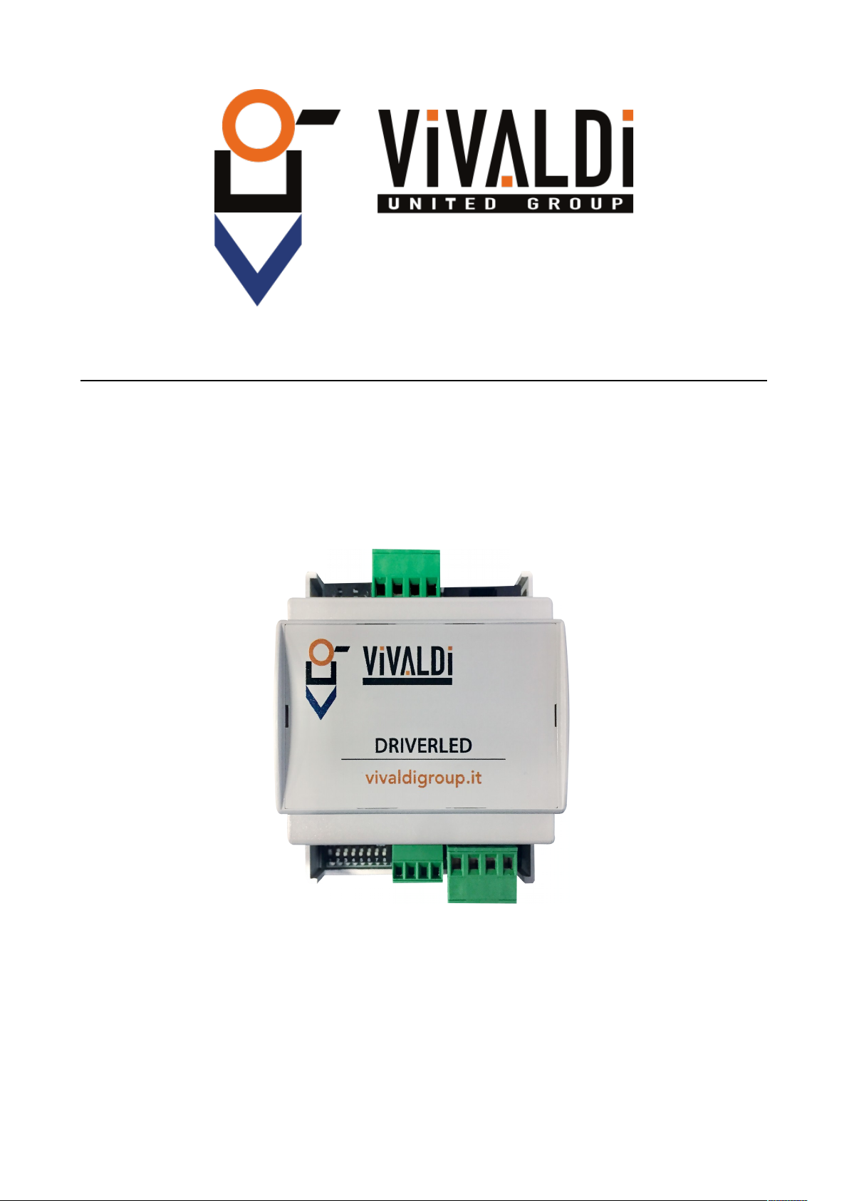
USER MANUAL
DRIVER LED
Page 2

Page 3

Indice
1 Important Safety Instructions..........................................................................................................2
2 description.......................................................................................................................................3
2.1 Layout description...................................................................................................................4
3 PACKAGE CONTENTS.................................................................................................................5
4 OPERATION...................................................................................................................................5
4.1 ELECTRIC CONNECTION...................................................................................................5
4.1.1 Single module connection................................................................................................5
4.2 USER MENU..........................................................................................................................7
4.2.1 CHANGE DEVICE ID....................................................................................................7
4.2.2 SWITCHING ALL DEVICES ON..................................................................................7
4.3 WEB SERVER.........................................................................................................................8
4.3.1 STATUS...........................................................................................................................8
4.3.2 LOCAL IP CONFIGURATION.......................................................................................9
4.3.3 CONNECTION CONFIGURATION............................................................................10
4.3.4 SYSTEM CONFIGURATION.......................................................................................11
4.3.5 RESTART......................................................................................................................12
5 COMMUNICATION PROTOCOLS............................................................................................13
5.1 MODBUS RTU PROTOCOL................................................................................................13
6 Technical specification..................................................................................................................14
1 DRIVER LED
Page 4

1 IMPORTANT SAFETY INSTRUCTIONS
This device is designed and manufactured to assure personal safety. Improper use can result in
electric shock or fire hazard. The safeguards incorporated into this unit will protect you if you
observe the following procedures for installation, use, and servicing.
• Follow all warnings and instructions marked on the product.
• Unplug this product from the wall outlet before cleaning. Do not use liquid cleaners or
aerosol cleaners. Use a damp cloth for cleaning.
• Do not use this product near any liquids.
• Do not place this product on an unstable surface. The product may fall, causing serious
damage to the product.
• Do not drop the product.
• Do not block the slots and openings on the top and bottom of the chassis; to ensure proper
ventilation and reliable operation of the product and to protect it from overheating, these
openings must not be blocked or covered.
• Operate this product only from the type of power indicated on the marking label.
• Do not allow anything to rest on the power cord. Do not locate this product where persons
will walk on the cord.
• Never push objects of any kind into this product through the chassis slots as they may touch
dangerous voltage points or short out parts that could result in a fire or electric shock.
• Unplug this product from the wall outlet and refer servicing to qualified service personnel
under the following conditions:
◦ When the power cord or plug is damaged or frayed.
◦ If liquid has been spilled on the product.
◦ If the product has been exposed to rain or water.
◦ If the product does not operate normally when the operating instructions are followed.
Adjust only those controls that are covered by the operating instructions since improper
adjustment may result in damage and require extensive work by a qualified technician to
the product to normal condition.
◦ If the product has been dropped or the chassis has been damaged.
◦ If the product exhibits a distinct change in performance, contact Vivaldi Customer
Support.
Vivaldi S.R.L. it reserves the right to update this document at any time without notice.
DRIVER LED 2
Page 5

2 DESCRIPTION
DRIVER LED is a device for the remote management of LED strips (1xRGB or 3xsingle colour).
Using RJ45 port it is possible to connect DRIVER LED to the local network and control it with
Vivaldi iControl or another smart home controller.
This product features an internal web server platform from which it is possible to access the
settings.
3 DRIVER LED
Page 6

2.1 LAYOUT DESCRIPTION
A) Power ON LED;
B) RJ45 plug, ethernet 10/100Mbps connection;
C) Euroblock socket 4-way, | B | A | - | + |, for power supply and RS485 connection for future
applications;
D) DIP SWITCH for address setting and test dip;
E) Euroblock socket 4-way, | B | G | R | +COM |, LED strips connection;
DRIVER LED 4
B
C
D
A
E
Picture 1
Page 7

3 PACKAGE CONTENTS
• DRIVER LED
• INSTRUCTION MANUAL
4 OPERATION
4.1 ELECTRIC CONNECTION
4.1.1 Single module connection
For a proper operation of the device, make sure to supply from 12 to 24Vdc through the socket
(Picture 1-C). Pay attention to polarity!
To start communications just connect the device to LAN network via the RJ45 plug (Picture 1-B)
using at least a CAT5e cable.
It is possible to connect a maximum load of 2A/Ch to the 3 outputs, Open Drain output with
common positive.
5 DRIVER LED
Page 8

4.2 USER MENU
4.2.1 CHANGE DEVICE ID
Set the DIP switch from n 2 to 8 (binary), LSB = 8. (Default: dip 8 ON, address 1)
MODBUS PROTOCOL:
• OUTPUT1-3 = ID 3-5
4.2.2 SWITCHING ALL DEVICES ON
To check that all electrical connections are correct it is possible to activate all outputs manually. Set
DIP1 on ON, the 3 outputs will be activated.
DRIVER LED 6
Picture 2
Page 9

4.3 WEB SERVER
The device has a built-in WEB SERVER for the management and configuration of contacts.
The default IP address is: 192.168.0.106, hence, after connecting the device to the network open
any web browser (eg. Firefox, Chrome, Safari, ecc…) and set the default IP address in the address
bar.
This will open the authentication page. Type in user name and password:
UTENTE: admin (default)
PASSWORD: admin (default)
4.3.1 STATUS
Once logged in you will be directed to DRIVER LED’s home page (Picture 3)
In Status menu it is possible to check the current status of the device.
7 DRIVER LED
Picture 3
Page 10

4.3.2 LOCAL IP CONFIGURATION
In this page it is possible to set the network parameters of DRIVER LED.
To save the settings click on save on the page bottom.
DRIVER LED 8
Picture 4
Page 11

4.3.3 CONNECTION CONFIGURATION
On this page it is possible to set the port and communication protocol with the smart home
controller.
To save the settings click on save on the page bottom.
9 DRIVER LED
Picture 5
Page 12

4.3.4 SYSTEM CONFIGURATION
In this page it is possible to set DRIVER LED devices’ name, webserver ports, user name and
password.
To save settings it click on save on the page bottom.
DRIVER LED 10
Picture 6
Page 13

4.3.5 RESTART
On this page it is possible to reset the device from remote.
11 DRIVER LED
Picture 7
Page 14

5 COMMUNICATION PROTOCOLS
For controlling DRIVER LED with VIVALDI iCONTROL+ other smart home systems
5.1 MODBUS RTU PROTOCOL
To communicate with MODBUS protocol set the registers as follows:
OUTPUT 1 REGISTER 3 (RED) VALUE FROM 0 TO 512
OUTPUT 2 REGISTER 4 (GREEN) VALUE FROM 0 TO 512
OUTPUT 3 REGISTER 5 (BLUE) VALUE FROM 0 TO 512
DRIVER LED 12
Page 15

6 TECHNICAL SPECIFICATION
Power supply 12-24Vdc
Maximum current absorbtion Depends on load
Maximum current Open drain OUTPUT= 2A EACH OUTPUT
Network communication 10/100Mbps
13 DRIVER LED
Page 16

MU_A84_11/18_D90
Vivaldi S.R.L.
Sede amministrativa
Via E. Fermi, 8 - Z. I. Est – 30020
Noventa di Piave (VE) Italia
tel. +39 0421 307825 fax +39 0421 307845
[email protected] www.vivaldigroup.it
www.vivaldigroup.it [email protected]
 Loading...