

Page 1
VITEK
VT-IPSN16M
ENVI Series 16 Channel
Network Video Recorder
• Supports up to 16 IP Cameras
• Supports 4 Mega pixel cameras at real-time / 8 Mega pixel at 15fps/
each / 16 Mega pixel cameras 7.5fps/each
• Audio recording & transmission
• Configuration and control through Web browsers
• Supports Hard Drives up to 2TB SATA
• Multi-Vendor camera support
• H.264 Compression
• RS-232 Serial port
• Gigabit Ethernet
• Built-in motion detection
• PTZ control
Page 2

ENVI Series: VT-IPSN16M
Table of Contents
1. Product Overview ..................................................................................................................... 6
1.1. VT-IPSN16M ................................................................................................................ 6
1.2. Key Features ................................................................................................................ 6
1.3. Specifications ............................................................................................................... 7
1.4. VT-IPSN16M Packing List .............................................................................................. 8
2. Hardware description ................................................................................................................ 9
2.1. VT-IPSN16M Front View ............................................................................................... 9
2.2. VT-IPSN16M Rear View .............................................................................................. 10
2.2.1. COM Port Description........................................................................................ 11
3. VT-IPSN16M Installation and Basic Setup ................................................................................. 12
3.1. Before Installation ...................................................................................................... 12
3.2. Factory Default Settings .............................................................................................. 12
3.3. Installing VT-IPSN16M ................................................................................................ 12
4. Software Installation ............................................................................................................... 13
5. IP Installer: Introduction ......................................................................................................... 16
6. Installing and Uninstalling ....................................................................................................... 16
6.1. Installing IP Installer .................................................................................................. 16
6.2. Uninstalling IP Installer ............................................................................................... 19
7. Using IP Installer .................................................................................................................... 22
7.1. Starting the Program .................................................................................................. 22
7.2. Search Product ........................................................................................................... 23
7.3. Manual Network Setup ............................................................................................... 24
7.4. Automatic Network Setup ........................................................................................... 26
7.5. Using DHCP Server ..................................................................................................... 29
7.6. Using PPPoE .............................................................................................................. 29
7.7. Updating Firmware ..................................................................................................... 31
7.8. Filter Configuration ..................................................................................................... 33
7.9. Live View ................................................................................................................... 34
8. ENVI Admin Menu .................................................................................................................. 36
8.1. Entering Admin Me nu ................................................................................................. 36
8.2. Admin Menu Structure ................................................................................................ 37
9. Quick Configuration ................................................................................................................ 37
9.1. Step 1: Changing Server Name ................................................................................... 37
9.2. Step 2: Time Setup .................................................................................................... 37
9.3. Step 3: Network Setup ............................................................................................... 37
9.4. Step 4: IPCCTVDNS.COM ............................................................................................ 38
1
Page 3

ENVI Series: VT-IPSN16M
9.5. Step 5: Recording Configuration .................................................................................. 38
9.6. Finish ........................................................................................................................ 38
10. System Configuration Menu .................................................................................................. 38
10.1. Server Name Setup..................................................................................................... 38
10.2. Date & Time............................................................................................................... 39
10.3. Admin Password ......................................................................................................... 40
10.4. Access Control ............................................................................................................ 40
10.5. User Registration ........................................................................................................ 40
10.5.1. Add ................................................................................................................. 40
10.5.2. Edit ................................................................................................................. 42
10.5.3. Delete ............................................................................................................. 42
11. Network Configuration .......................................................................................................... 42
11.1. Static IP Configuration ................................................................................................ 43
11.2. DHCP Client Configuration ........................................................................................... 43
11.3. PPPoE Configuration ................................................................................................... 44
11.4. Network Ports ............................................................................................................ 44
11.5. Bandwidth Control Configuration ................................................................................. 45
11.6. View Network Status................................................................................................... 45
11.7. Network Status Notify ................................................................................................. 46
11.8. IP-CCTV DNS Setup .................................................................................................... 47
11.9. Port Forwarding & UPnP ............................................................................................. 48
11.10. RTP/RTSP Setup ......................................................................................................... 49
12. Device Configuration ............................................................................................................ 51
12.1. Privacy Zone .............................................................................................................. 51
12.2. Camera & Motion ....................................................................................................... 53
12.2.1. Camera Configuration....................................................................................... 55
13. Advanced Configuration ........................................................................................................ 59
13.1. Advanced Services ...................................................................................................... 60
13.1.1. E-mail Service Configuration ............................................................................. 61
13.1.2. FTP (Buffered) Ser vice Configuration ................................................................. 64
13.1.3. FTP (Periodic) Service Configuration .................................................................. 66
14. Recording Configur ation for Cameras with microSD card ........................................................ 68
14.1. MicroSD Configuration ................................................................................................ 68
14.2. Recording Configuration with microSD card .................................................................. 71
15. Utilities ................................................................................................................................ 74
15.1. System Log ................................................................................................................ 75
15.2. Save Configuration ..................................................................................................... 75
15.3. Reboot ....................................................................................................................... 75
15.4. Factory Default ........................................................................................................... 76
2
Page 4

ENVI Series: VT-IPSN16M
15.5. System Update ........................................................................................................... 76
16. ENVI Series Viewer............................................................................................................... 79
16.1. Introduction ............................................................................................................... 79
16.2. Key Features .............................................................................................................. 79
16.3. System Requirement for PC......................................................................................... 79
17. Installing and Uninstalling ..................................................................................................... 80
17.1. Installing ENVI Series Viewer ...................................................................................... 80
17.1.1. Installing on Web Browser ................................................................................ 80
17.1.2. Manual Installation ........................................................................................... 82
17.2. Uninstalling ENVI Series Viewer ................................................................................... 83
17.2.1. Uninstalling with Program Menu ........................................................................ 83
17.2.2. Uninstalling on Control Panel ............................................................................ 84
18. Starting ENVI Series Viewer .................................................................................................. 85
18.1. Control Bar ................................................................................................................ 86
18.2. Channel Control Bar .................................................................................................... 87
18.3. OSD Channels Buttons ................................................................................................ 87
18.3.1. Saving as Image File ........................................................................................ 87
18.3.2. Saving as Video File ......................................................................................... 88
18.3.3. Manual Recording ............................................................................................ 88
18.3.4. Instant Playback .............................................................................................. 89
18.4. Extended Features ...................................................................................................... 90
18.4.1. Pausing Live Video ........................................................................................... 90
18.4.2. FPS Control ..................................................................................................... 90
18.4.3. Flip Control ...................................................................................................... 91
19. EN-V-R: Introduction ............................................................................................................ 92
20. Requirements for Installation ................................................................................................ 93
20.1. EN-V-R Ver sions ......................................................................................................... 93
20.2. System Requirement for PC......................................................................................... 93
21. Installing EN-V-R .................................................................................................................. 94
22. Uninstalling EN-V-R .............................................................................................................. 96
22.1. Closing Active EN-V-R ................................................................................................. 96
22.2. Executing Uninstaller .................................................................................................. 97
23. Components of EN-V-R Program ........................................................................................... 98
23.1. EN-V-R Configurator ................................................................................................... 98
23.2. EN-V-R Service ........................................................................................................... 98
23.3. EN-V-R Controller ....................................................................................................... 98
23.4. EN-V-R System Tray Menu .......................................................................................... 99
24. Starting EN-V-R Configurator ................................................................................................ 99
25. Quick Start Guide ............................................................................................................... 101
25.1. EN-V-R Configurator User Interface ........................................................................... 101
3
Page 5

ENVI Series: VT-IPSN16M
25.2. Searching for IP Devices ........................................................................................... 102
25.3. Registering IP Devices .............................................................................................. 103
25.4. Viewing Live Video ................................................................................................... 106
25.5. Recording Video ....................................................................................................... 107
26. ENVI Smart Player .............................................................................................................. 112
26.1. Introduction ............................................................................................................. 112
26.2. Key Features ............................................................................................................ 112
26.3. System Requirement for PC....................................................................................... 112
27. Installing and Uninstalling ................................................................................................... 113
27.1. Installing Smart Player .............................................................................................. 113
27.1.1. Manual Installation ......................................................................................... 113
27.2. Uninstalling Smart Player .......................................................................................... 115
27.2.1. Uninstalling on Prog ram Menu ........................................................................ 115
28. Configuring & Viewing Player .............................................................................................. 125
28.1. Main Window View ................................................................................................... 126
28.2. Connecting to NVR Player ......................................................................................... 127
28.3. Creating a Group ...................................................................................................... 127
29. Searching Video ................................................................................................................. 129
29.1. Searching Video ....................................................................................................... 129
29.2. Daily Search ............................................................................................................. 129
29.2.1. Search Mode .................................................................................................. 130
29.2.2. GO to Time Position ....................................................................................... 130
29.3. Condition Search Mode ............................................................................................. 130
29.3.1. Advanced Search Mode .................................................................................. 131
30. Video Playback C ontrols ...................................................................................................... 132
31. Extra Features ................................................................................................................... 133
31.1. Window Control ........................................................................................................ 133
31.2. Recording Period ...................................................................................................... 133
31.3. Backup .................................................................................................................... 134
31.4. Snapshot ................................................................................................................. 135
31.5. Print ........................................................................................................................ 136
31.6. Ratio Display ............................................................................................................ 136
32. EN-V-R Configuration ......................................................................................................... 138
32.1. System, Network Configuration ................................................................................. 138
32.1.1. Configuring System name ............................................................................... 138
32.1.2. System, Network Configuration - Admin password ........................................... 139
32.1.3. System, Network Configuration - Access Control .............................................. 139
32.1.4. System, Network Configuration - HTTP Port..................................................... 140
32.1.5. System, Network Configuration–IP CCTV-DNS ................................................. 140
33. IP-CCTV DNS Registration .................................................................................................. 141
4
Page 6

ENVI Series: VT-IPSN16M
34. IP-Device Registration ........................................................................................................ 147
34.1. IP-Device Registration (Manual) ................................................................................ 147
34.2. IP-Device Registration (Automatic) ............................................................................ 149
IP-Device Modific ation ................................................................................................. 151
34.3. IP-DeviceDeletion ..................................................................................................... 153
34.4. IP-Device Homepage ................................................................................................ 153
34.5. Camera Management ................................................................................................ 153
34.5.1. Configure Camera Name and Information ........................................................ 154
34.5.2. Camera Resolution, Quality ............................................................................. 155
34.5.3. Configure Camera Recording Condition ........................................................... 156
34.5.4. Alarm, Event Configuration ............................................................................. 159
34.6. User Management .................................................................................................... 160
34.6.1. User Registration ........................................................................................... 161
34.6.2. User Modification ........................................................................................... 162
34.6.3. User Deletion ................................................................................................. 162
34.7. Disk Setup ............................................................................................................... 162
34.7.1. Disk Setup ..................................................................................................... 162
34.7.2. Disk Quota Modification and Deletion .............................................................. 162
34.7.3. Disk Mode Change ......................................................................................... 163
34.8. Utilities .................................................................................................................... 165
34.8.1. Email account Configuration ........................................................................... 166
34.8.2. About Program .............................................................................................. 167
35. Using EN-V-R Controller ...................................................................................................... 167
36. Connecting to EN-V-R ......................................................................................................... 168
36.1. PC with EN-V-R installed ........................................................................................... 168
36.2. PC without EN-V-R.................................................................................................... 170
5
Page 7
ENVI Series: VT-IPSN16M
1. Product Over view
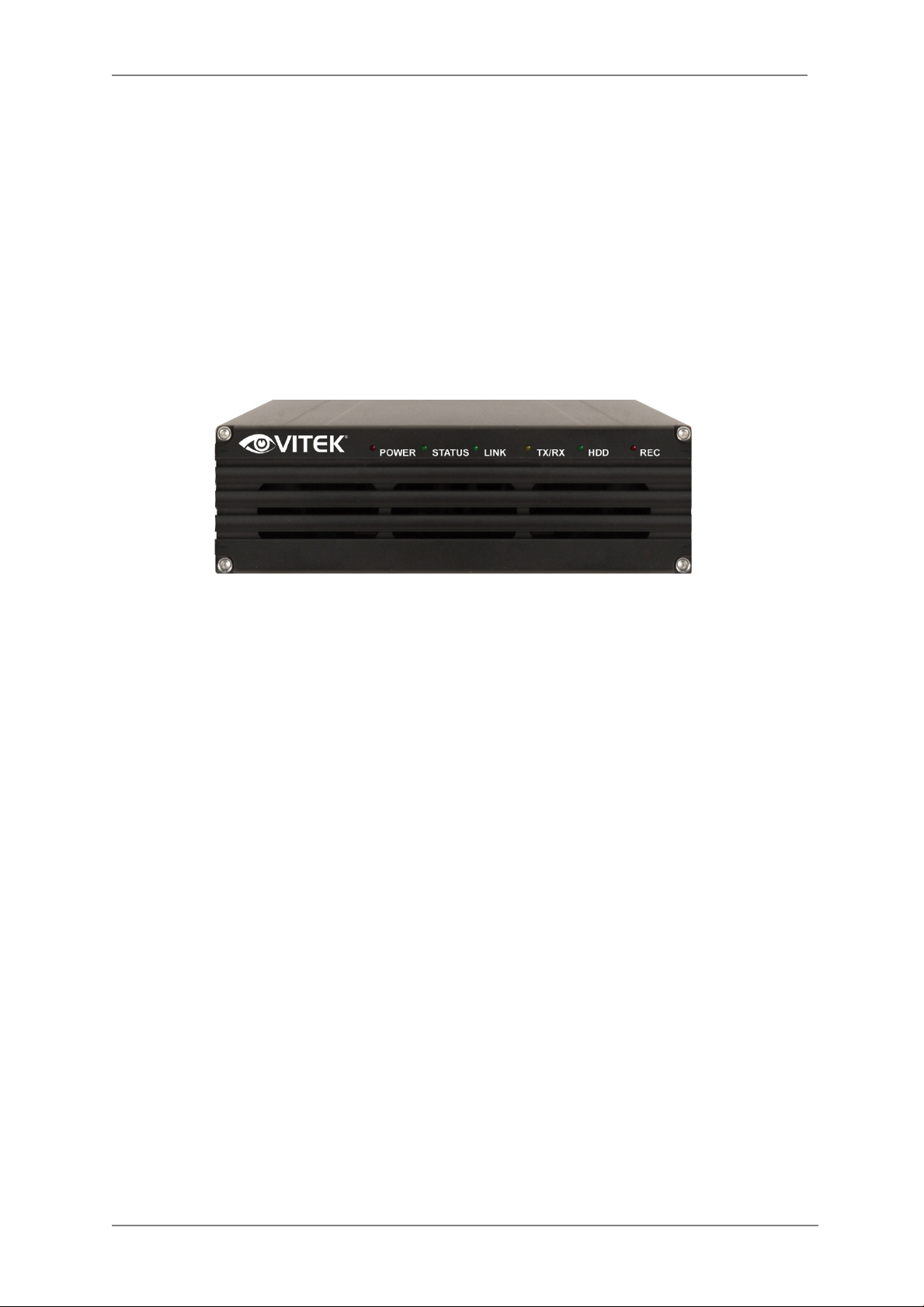
1.1. VT-IPSN16M
VT-IPSN16M is a stand-alone 16 channel high-performance network video recorder. A fully Internet
Explorer browser enabled network video recorder that, can display, record and playback real time
MJPEG, MPEG4 and H.264 video streams transmitted from any VITEK IP camera or video server
over a TCP/IP network. It also supports other major brands of IP cameras and Video Servers
including Axis, Panasonic, Mobotix, Arecont Vision, IQinvision, and Vivotek.
Picture 1 : VT-IPSN16M
1.2. Key Features
ENVI 16 Channel Network Video Recorder
• Supports up to 16 IP Cameras
• Supports 4 Mega pixel cameras at real-time / 8 Mega pixel at 15fps/each / 16 Mega pixel
cameras 7.5fps/each
• Audio recording & transmission
• Configuration and control through We b browsers
• Supports up to 2TB SATA Hard Drives
• Multi-Vendor camera support
• H.264 Compression
• RS-232 Serial port
• Gigabit Ethernet
• Built-in motion detection
• PTZ control
6
Page 8

ENVI Series: VT-IPSN16M
One serial ports for console, modem (PSTN & GSM), serial input/output device,
Live-cast for up to 16x8 Channel
1.3. Specifications
Hardware
Video compression
Recording
Transmission or
Recording
(Single Mode)
Transmission and
Recording
(Duplex Mode)
Transmission and
Recording and Playback
(Triplex Mode)
32bit Embedded CPU
Flash 8Mbytes /SDRAM: DDR2 128Mbytes
Linux version 2.6.24.4 operating system
Battery backed up real-time clock
MJPEG
MPEG-4
H.264
2 Step frame rate (Fast on event/Slow on continuous recording mode)
Supports Linux File system
Supports max 2 Tb SATA HDD
Anti-shock system
Performance (1000Base-T / LAN)
Trans : 120fps(NTSC)/100fps (PAL)
Rec : 120fps(NTSC)/100fps (PAL)
when Single Mode with all channels at HD
Performance (1000Base-T / LAN)
Trans : 120fps(NTSC)/100fps (PAL)
Rec : 120fps(NTSC)/100fps (PAL)
when Duplex Mode with all channels at HD
Performance (1000Base-T / LAN)
Trans : 120fps(NTSC)/100fps (PAL)
Rec : 120fps(NTSC)/100fps (PAL)
when Triplex Mode with all channels at HD
LAN interface 10/100/1000 BaseT Ethernet auto sensing
Serial Interface
Management
Developer suppor t
PWR Consumption
Operating Environment
Miscellaneous
Users
COM Port is RS-232,
Max Baud rate: 115200 bit/s
Configurable by serial, web or telnet
Remote system update via telnet, FTP or web browser
Provides HTTP CGI API
ActiveX control development kit
DC 12Volt
Max: 1.8 A
Normal : 1.0 A
(with Seagate Barracuda ES.2 1000Gbyte)
Temperature : 32° ~ 122°F (0° ~ 50°C)
Humidity : 20 ~ 80% RH(non-condensing)
Work with EN-V-R (CMS software)
Dynamic IP support through IPCCTVDNS Server
Playback for up to 16 clients
Installation,
management and
7
Installation CD and web-based configuration
Firmware upgrades over HTTP, telnet & FTP, firmware available at homepage
Page 9
maintenance
Pentium 4, 2 GHz, 2GB(RAM) or hig her
KCC
ENVI Series: VT-IPSN16M
Video access from Web
browser
Minimum Web
browsing requirements
Supported protocols HTTP, TCP/IP, FTP, Telnet, RARP, PPPoE, PAP, CHAP, DHCP, NTP, SMTP client
Approvals
Dimensions (L x W x H)
/ Weight
Video access from Web browser
Video Card: 256MB RAM, 1024x768 resolution or higher
100Mbps Network Adaptor or faster
Windows XP Pro or later
Internet Explorer 6.x or later
FCC : Class A
CE : Class A
RoHS
8.82” x 5.51” x 1.73” (224 x 140 x 44mm) / 2.09 lbs. (0.95kg) – w/o power
supply or HDD.
* All specifications are subject to change without prior notice.
Table 1 : Specification for VT-IPSN16M
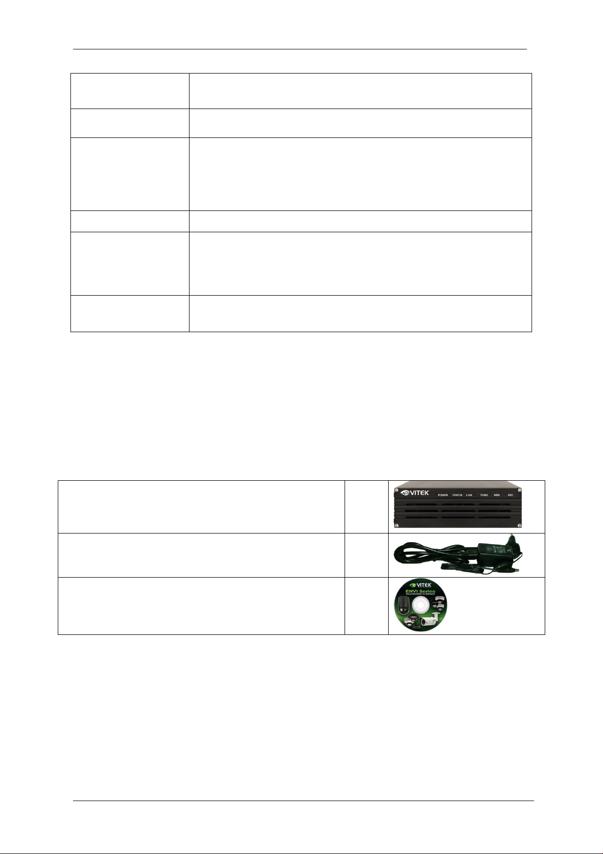
1.4. VT-IPSN16M Packing List
VT-IPSN16M includes the following items
VT-IPSN16M 1 EA
Power Supply Unit
(Power Cable & SMPS DC12V 5A Adapter)
CD (User’s Manual, IP Installer and etc) 1 EA
1 EA
Table 2 : VT-IPSN16M Packing list
8
Page 10
ENVI Series: VT-IPSN16M
PART
DESCRIPTION
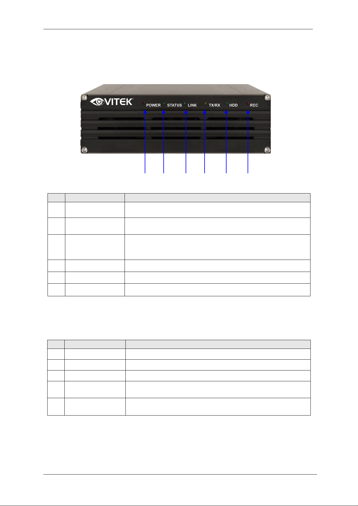
2. Hardware description
2.1. VT-IPSN16M Front View Picture 2 : VT-IPSN16M Front pan el
A B C D E F
A POWER LED Red LED is on when power is provided.
B STATUS LED
C LAN LINK LED
D LAN(Tx/Rx) LED Yellow light blinks with data transmission over LAN.
E HDD LED Green light blinks when formatting or recording on HDD.
F RECORDING LED Red light blinks when recording to HDD
Indicates the status of operation & shutdown of VT-IPSN16M.
Green LED turns on during normal operation after VT-IPSN16M boots.
Indicates the status of access to LAN
Table 3 : VT-IPSN16M Front panel
Beep Sound Description
Name Description
1 POWER ON One short Beep when power is turned on.
2 SYSTEM READY Two Beep’s after boot-up
3 POWER OFF Two short Beep’s on power down
4 HDD ERROR
FACTORY DEFAULT
5
BUTTON
Beep’s continuously for five seconds when HDD has an error.
Beep’s one time (0.5 sec) after three seconds and then beep’s three
times shortly after another three secon ds.
Table 4 : VT-IPSN16M Beep Sound
9
Page 11
ENVI Series: VT-IPSN16M
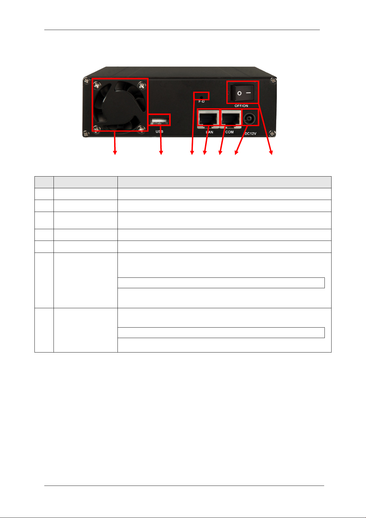
2.2. VT-IPSN16M Rear View
Picture 3 : VT-IPSN16M Real panel
A B C D E F G
PART DESCRIPTION
A Cooling FAN HDD Cooling FAN
B USB USB port (reserved for future use)
C
D LAN LAN port
E COM RS 232
F Power
G Power Switch
Factory Default
Switch
To Factory Default System
Push the switch for 7 secs after system booting.
DC 12V 5A
Do not cycle power until HDD and Fan have stopped
Used to switch on/off power
Do not cycle power while formatting HDD (may damage HDD)
Table 5 : VT-IPSN16M Rear panel
10
Page 12
ENVI Series: VT-IPSN16M
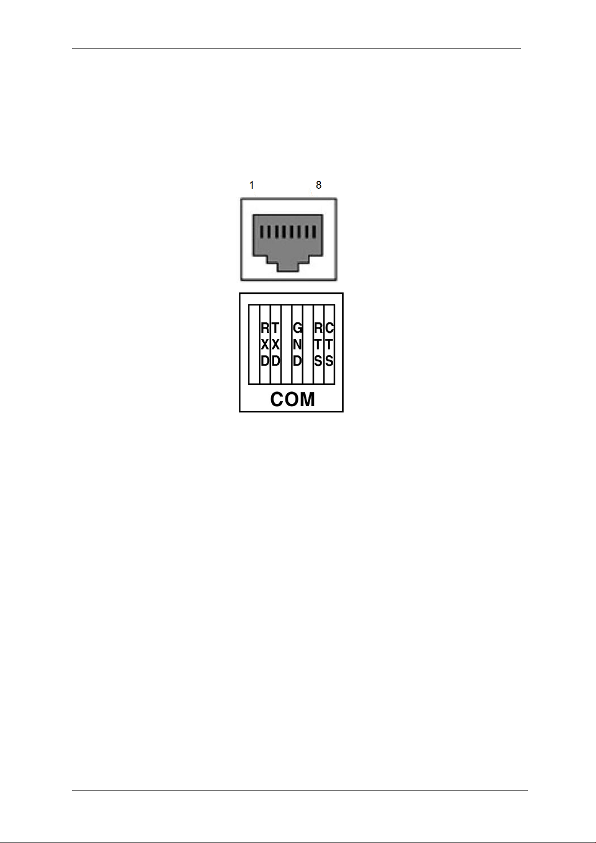
2.2.1. COM Port Description
Below image illustrates PIN No. of COM Port, Numbers are displayed in order from the left.
For RS-232 connection, RXD & TXD & GND are used only in general, RXD and TXD should be
crossed to communicate properly in case it connects with PC one by one.
Picture 4 : COM Port Description
11
Page 13

ENVI Series: VT-IPSN16M
3. VT-IPSN16M Installation and Basic Setup
3.1. Before Installation
• Carefully read the User's Manual.
• Check Network Configuration (IP Address, Network Mask and default gateway)
• Obtain an IP address for the VT-IPSN16M.
3.2. Factory Default Settings
The following table shows the factory default condition. Please refer to this when you need to
change the values in the admin menu.
Factory Default
Admin ID root
Admin password root
IP address 10.20.30.40
Network mask 255.255.255.0
Gateway 10.20.30.1
Table 5: Factory Default
Note: Factory default Admin ID and Password are all lower case...
3.3. Installing VT-IPSN16M
For installation of VT-IPSN16M, please follow the steps below.
1. install the VT-IPSN16M in place w ith adequate ventilation
2. Connect the VT-IPSN16M to the Network through the LAN port.
3. Connect the power supply of VT-IPSN16M.
Refer to the following sections for p rogramming and viewing
• Network Configuration: Refer to “IP Installer User’s Manual”
• Camera Configuration: Refer to “Vitek Adm in Menu User’s Manual”
• Service Configuration: Refer to “Vitek Admin Menu User ’s Manual”
12
Page 14
ENVI Series: VT-IPSN16M
4. Software Installation
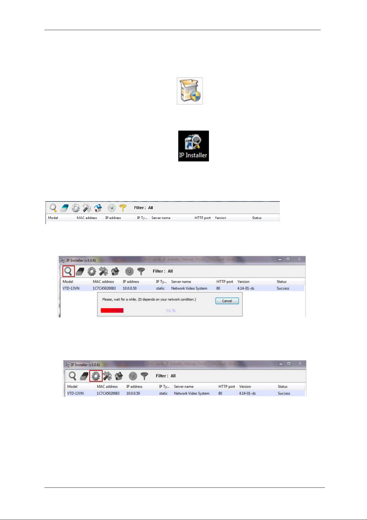
1. Run IP Installer Software from the CD program on a computer that is on the same network
as the IP camera.
2. Start IP Installer, by double clicking the icon “IP Installer”
3. After the program has started, the main window of IP Installer program will appear on the
screen as shown belo w.
4. Search for the installe d camera on the networ k by clicking the search product icon, the
camera should appear as the image below. The de fault IP address is 10.20.30.40
5. To assign an automatic IP address to this camera within the network, click the “Automatic IP
Setup” icon
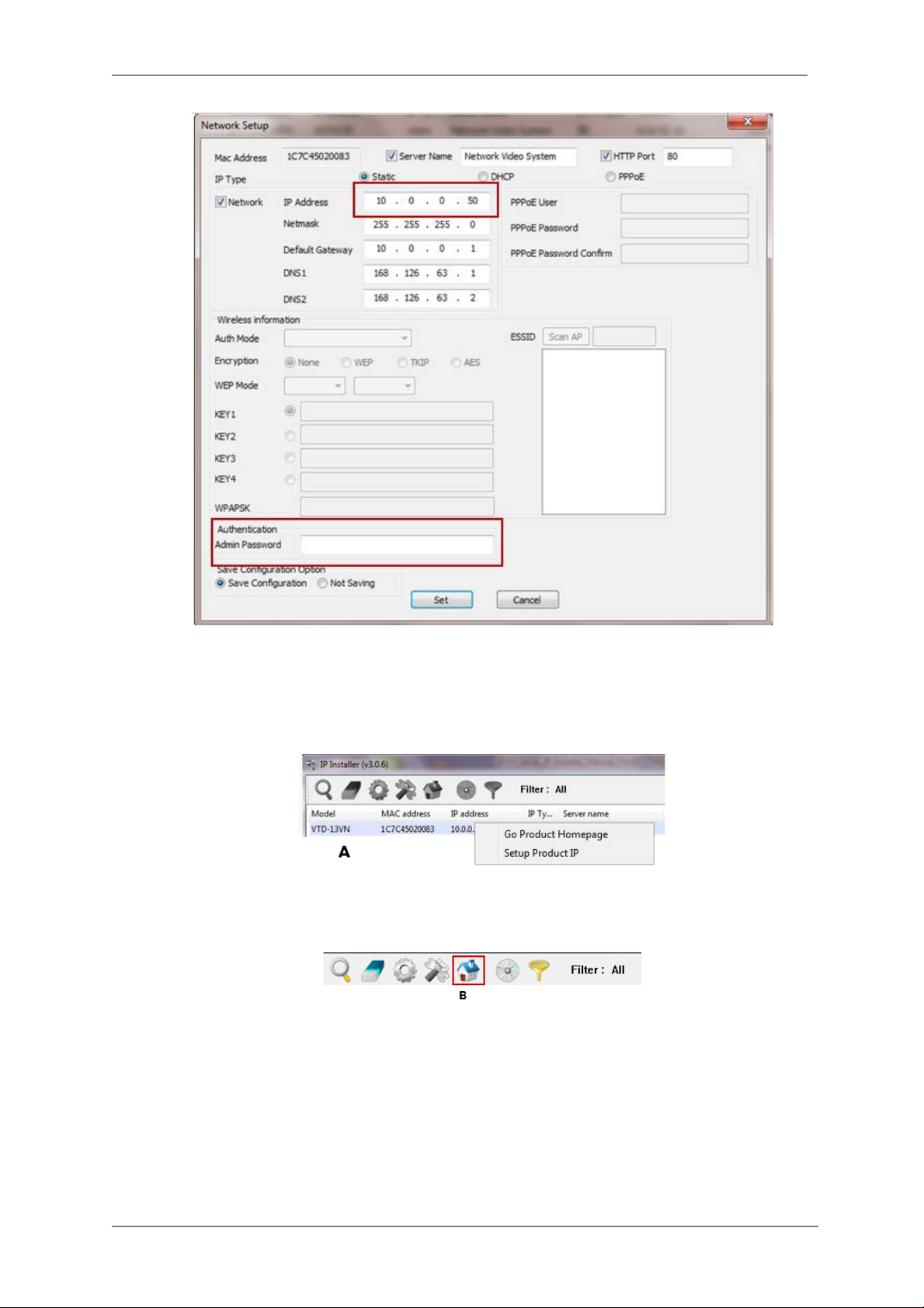
6. Verify the Automatic IP address provided, enter the default password root and then click Set
as shown below.
13
Page 15
ENVI Series: VT-IPSN16M
7. After the camera was configured by the program automatically, you will be able to get access
by
a) Right click over the camera information, “
b) Click over the icon “
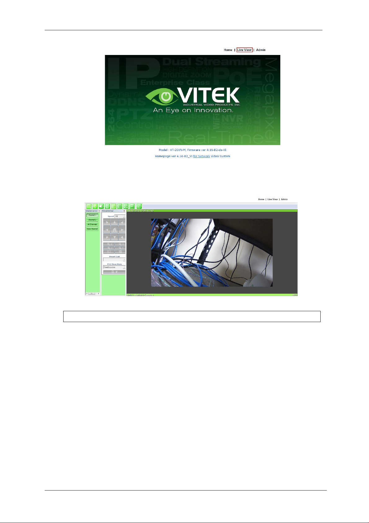
8. From the Home Page, you can “
Connect Product Homepage
Live View”
Go Product Homepage
”
or administrate
“Admin”
”
the camera.
14
Page 16
ENVI Series: VT-IPSN16M
On Live View you will be able to see live video from your camera.
NOTE: For more information, re fe r to Section 11. ENVI Admin Menu on page 36
.
15
Page 17
ENVI Series: VT-IPSN16M
5. IP Installer: Introduction
IP Installer is a proprietary utility program for Vitek IP products. It enables users of Vitek products
to search their network for any Vitek network camera, video server, or network video recorder no
matter what IP address it has. By using IP Installer, u sers will be able to facilitate network setup
process for Vitek products deployment.
Runs on Microsoft Windows operating system (XP, Vista, 7, 8)
Search for Network Cameras, Video Servers, and Network Video Recorders
Capable of firmware updating
Support automat ic and manual IP setup
6. Installing and Uninstalling
** It’s recommended to install this program as an administrator **
6.1. Installing IP Installer
If the program is started from the CD supplied with Vitek products, insert the CD in to CD/DVD tray
and check the installation file. If it is download or copied from the Internet or any other media,
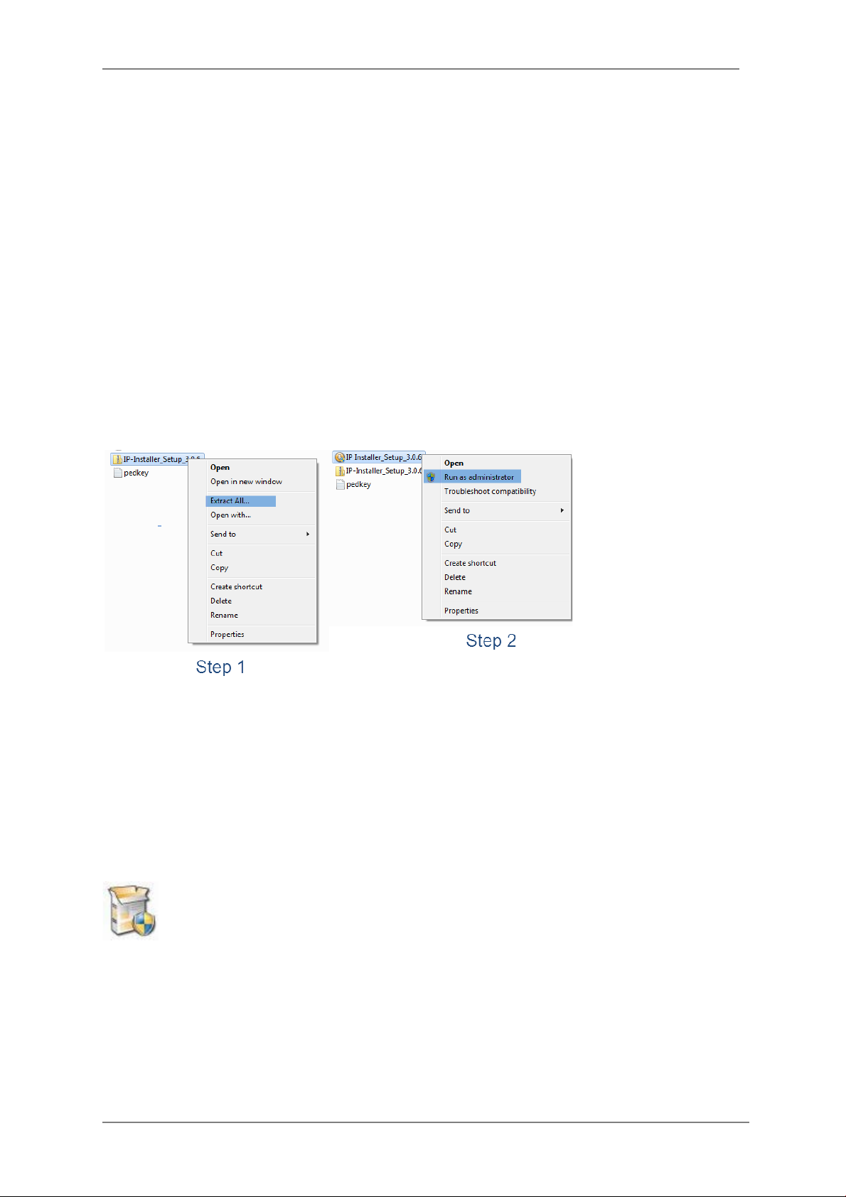
locate the file from the PC’s hard drive. You will see the icon as shown with the file name IP
Installer_Setup_x.x.x.exe. The actual file name in your case may vary as the version changes.
Double click the icon to star installation.
16
Page 18
ENVI Series: VT-IPSN16M
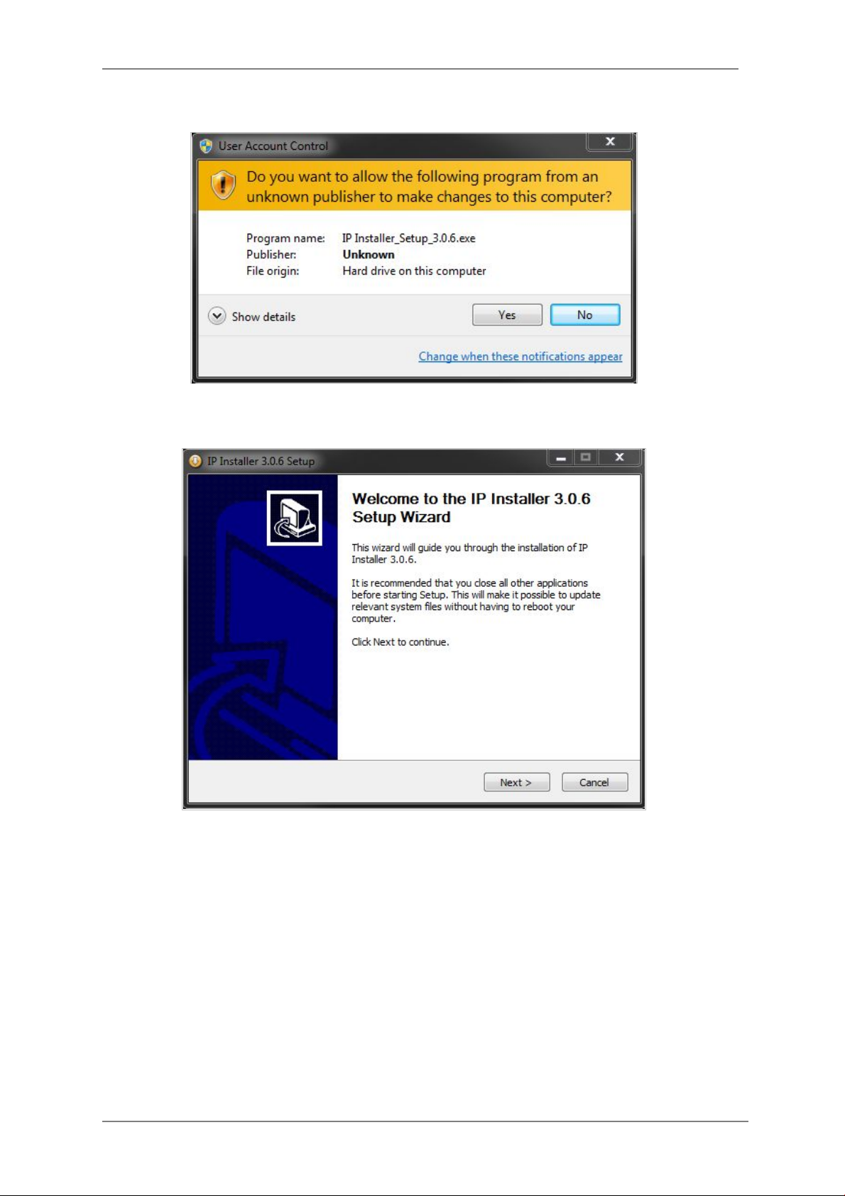
You may be prompted to co ntinue running the installation program.
Click Yes button, then the following window will be shown on the screen.
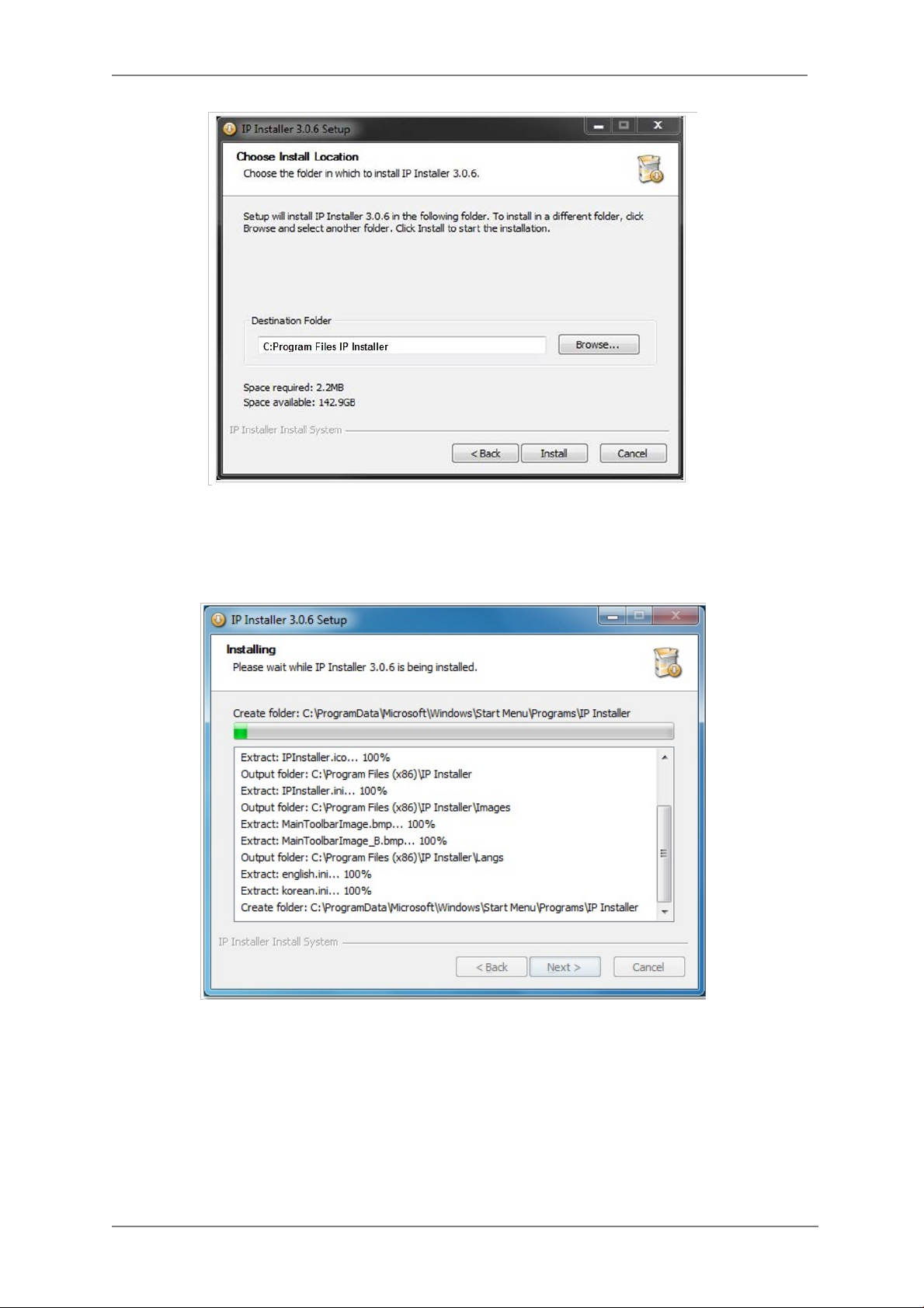
To continue the installation, click Next. The following window will be displayed for location to
install.
17
Page 19
ENVI Series: VT-IPSN16M
The default location for installation is C:\Program Files\IP Installer. It is recommended to install
in this folder, if you want to change it to a different location, click the Browse button to choose
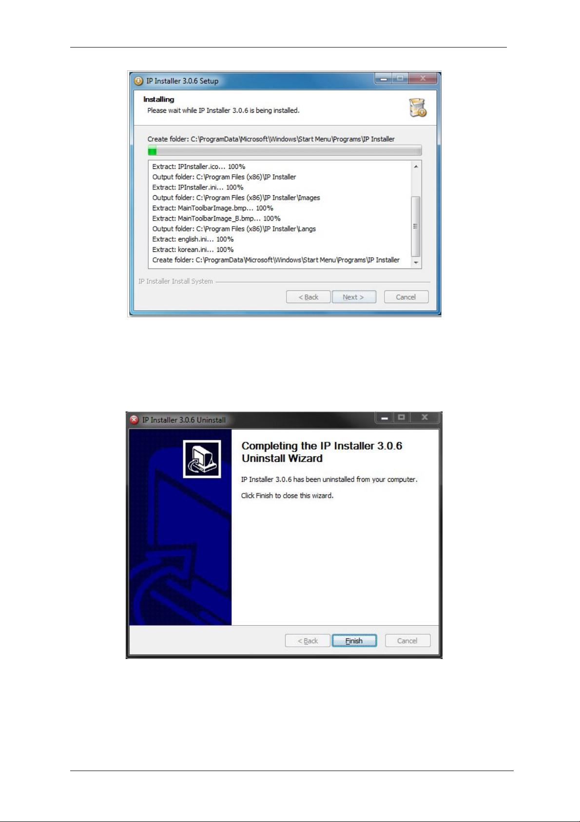
location. Now click the Install button. You will see the progress of the install as shown below.
18
Page 20
ENVI Series: VT-IPSN16M
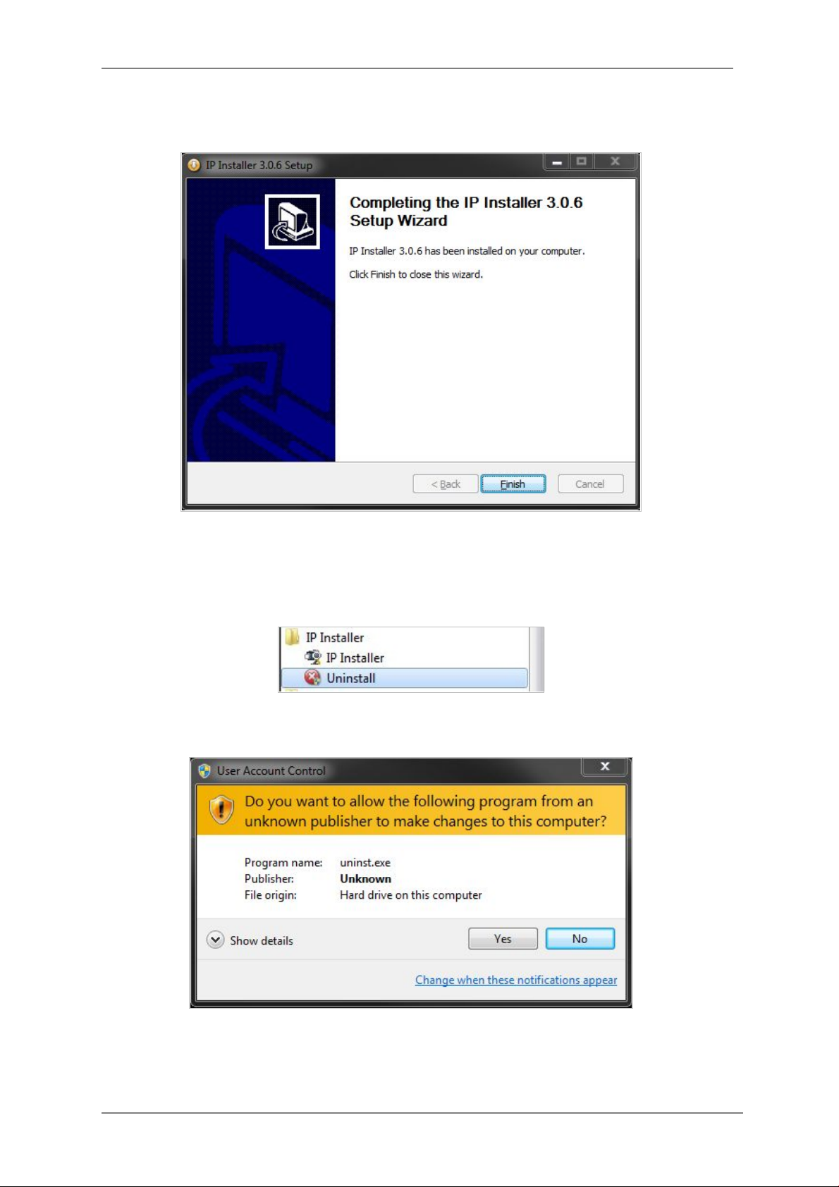
When the files are done copying, the foll owing window will be shown. Click the Finish button to
complete the installation.
6.2. Uninstalling IP Installer If you want to remove the IP Installer program from your PC, click Start > All Programs > IP
Installer > Uninstall.
You may be prompt to continue running the uninstall program.
19
Page 21
ENVI Series: VT-IPSN16M
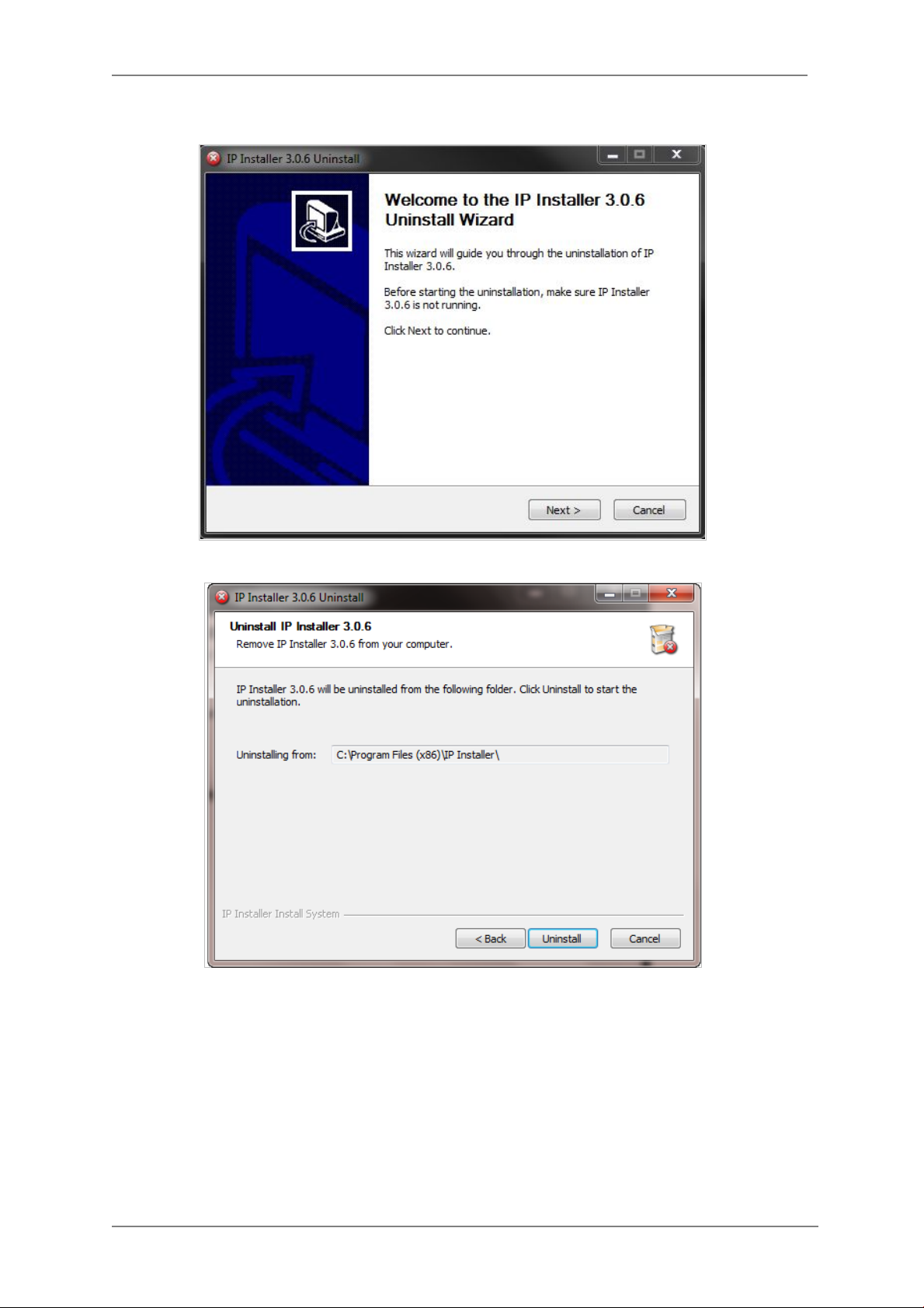
Click on the Yes button, then the following window will be shown on the screen.
Click on the Next butt on and you will see the following window.
Click on the Uninstall button to start removing the IP Installer program from your computer.
The following window will be displayed.
20
Page 22
ENVI Series: VT-IPSN16M
Click on the Finish button to close the window
21
Page 23
ENVI Series: VT-IPSN16M
7. Using IP Installer
7.1. Starting the Program
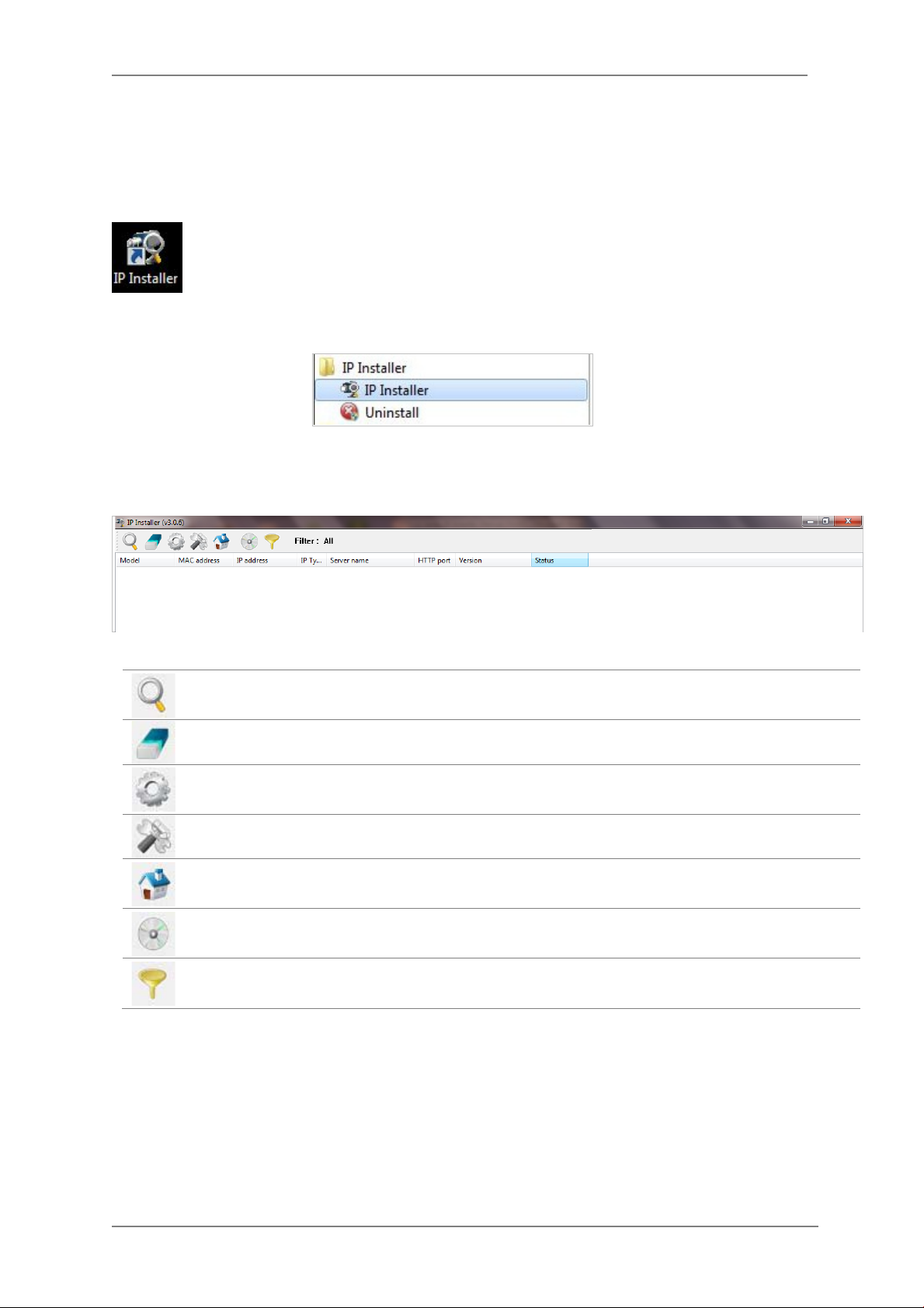
Once IP Installer program has bee n installed on your comput er, a shortcut icon
should be created on the desktop of your computer. You can s tart IP Installer by
double clicking the icon.
Or you can also start the program by clicking Start > All Programs > IP Installer > IP
Installer as shown below.
After the program has started, the main window of IP Installer program will appear on the
screen as shown belo w. There are no network devices shown, as it is the first time running the
program and nothing has been registered.
Search Product
Clear Product List Clear the Vitek products list created by searching the network.
Automatic IP Setup Configure the network setting of selected IP device in Automatic mode.
Manual IP Setup Configure the network setting of selected IP device in Manual mode.
Connect Product
Homepage
Update Firmware Update the firmware of the selected IP device.
Filter Configuration Define the range of MAC and IP addresses to search.
Scan the network and shows the list of all the Vitek products that IP
Installer program found.
Connect to the server homepage of the selected IP device.
22
Page 24
ENVI Series: VT-IPSN16M
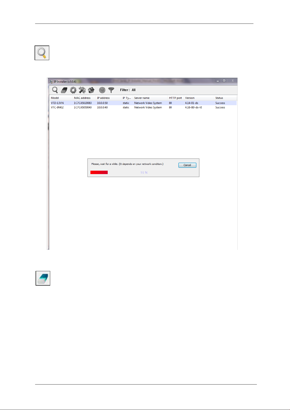
7.2. Search Product
Make sure that your Vitek products are powered and connected to the network, and then
click the Search Product button. A status window will pop up to show the progress of
the search. Wait until it reaches 100%, or you may pre ss the Cancel button to stop the
search at any given time and proceed with the results made until that moment.
After searching is completed 100%, the IP Installer program will display the IP devices found.
If you want to clear the list of the IP Devices from the window, click Clear Product List
button from the Main Toolbar .
23
Page 25
ENVI Series: VT-IPSN16M
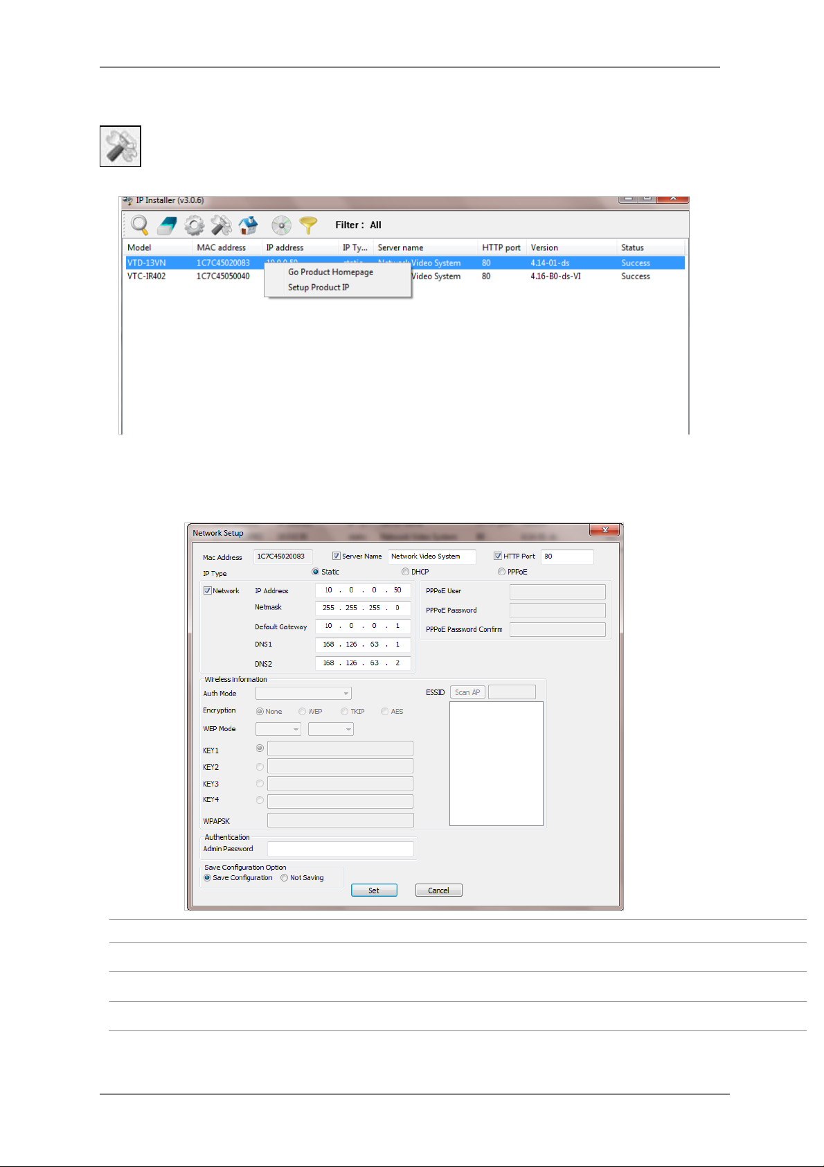
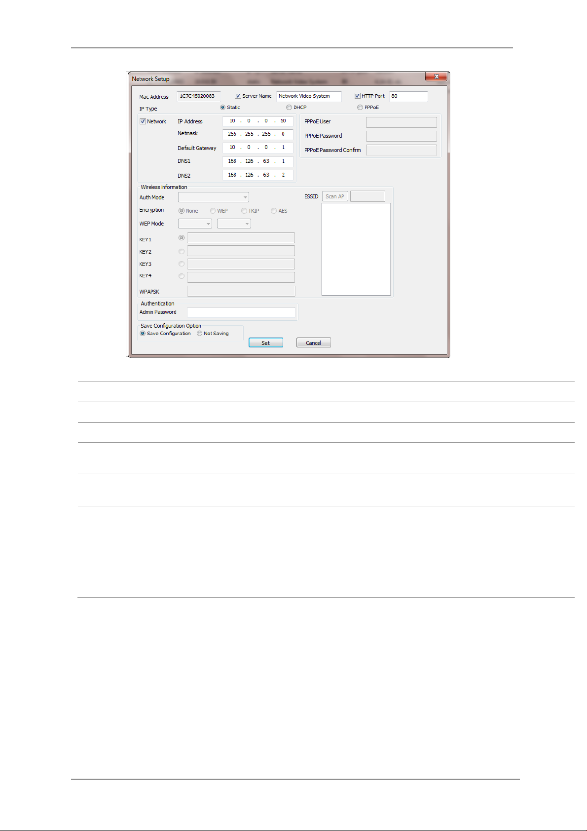
7.3. Manual Network Setup
Configuring the network parameters of the devices in the list can be started either by
highlighting and right clicking mouse button or by clicking Manual IP Setup button on
the main Toolbar.
When one IP device is selected, the following screen will appear
MAC Address MAC address of the selected device is shown.
Server Name Input desired name of camera i.e. Lunch Room
HTTP Port Input port number to access IP devices homepage via web. Default port is 80
IP Type Select the type of address (Static / DHCP / PPPoE) Use STATIC for manual IP setup
24
Page 26
ENVI Series: VT-IPSN16M
Network
Authentication
(Admin Password)
Save Configurati on
Option
Click Set button to ap ply the changed values to IP device. If you don’t want it, click Cancel button.
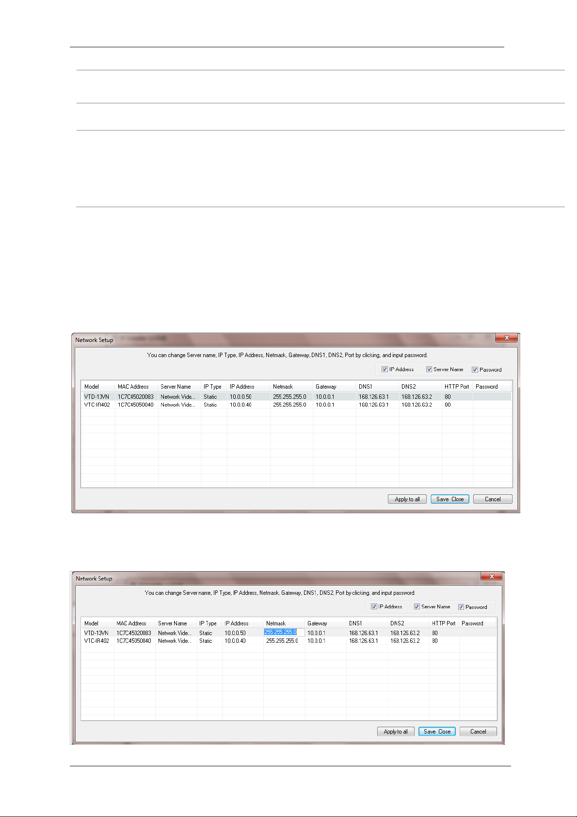
When two or more IP devices are selected
You can select two or more IP devices at the same time by clicking one after another while CTRL
key is pressed. The result is shown as below.
To configure the network parameters of those devices, click the right mouse button or click
Manual IP Setup icon on the main Toolbar with multiple IP devices selected as shown above.
Then the following window will show up.
General network parameters are required in this part. Please contact your network
administrator for detail.(IP Addr es s , Netmask, Default Gateway, DNS1, DNS2)
Password for the IP device.
(Default password for Vitek products is “root” unless already changed)
Select whether the configured contents is to be saved in the Camera memory or not.
• Save Configuration: Changed values will be saved in the Camera memory of the
device, which means the changes are permanent.
• Not Saving: Changed values will not be saved in the Camera memory, which
means if the IP device is turned off the changes are lost and the previous setting
will be applied back.
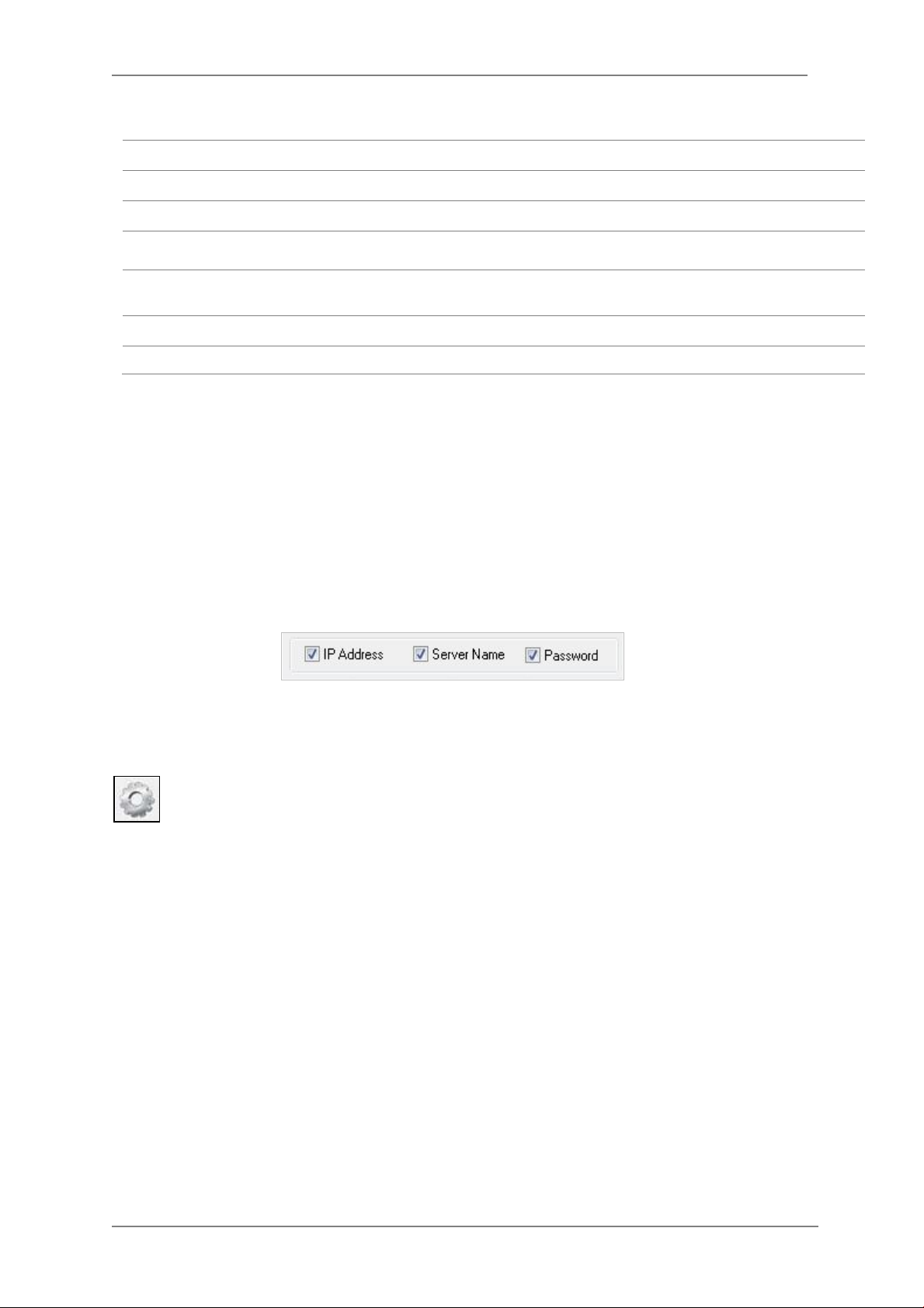
You can modify the value of each changea b le field by clicking it. The following shows an example
of entering a new value to a field.
25
Page 27
ENVI Series: VT-IPSN16M
Static
Model Model Numbers of the IP devices that you selected.
MAC Address MAC address of the selected device is shown.
Server Name Name of the selected IP device.
IP Type
IP address, Netmask,
Gateway, DNS1, DNS2
HTTP Port HTTP port number of the IP device for web access to homepage.
Password Password for the IP device.(Default password for Vitek products is “root”)
If you click Apply to all button a fter changing just a field of one IP device, the remaining IP
devices will have the same value for that parameter. In this case, each device’s Server name and
IP Address field will have +1 incremented value added to the original value. For example, if the
first IP device has been given the server name of NetCam and Apply to all button is pressed, it
will be automatically changed to NetCam1 and the next IP device will have NetCam2 and so on.
The same applies to the IP address field.
How to assign IP address to the device (Select
Setup)
General network parameters are required in this part. Please contact your
network administrator for d etail.
here for Manual IP
For Password field, the entered information doesn’t increment but will use the same data.
In using Apply to all, you can choose which field is affected. Put check marks o nly on the field
you want to use this automatic action as below.
Click Save & Close button to save the changed values in the camera memory of all the IP devices
and close the Network setup window.
7.4. Automatic Network Setup
Configuring the network parameters of the devices in the list can be started either by
clicking right mouse button or by clicking Automatic IP Setup button on the main
Toolbar. Before starting the setup, you first need to c hoose the one to be configured. In
this setup mode, IP Installer program checks your local network and assigns available IP addresse s
to the IP devices. You have a choice of using those automatically assigned IP addresses, or you
can just enter other IP addresses as you desire.
26
Page 28
ENVI Series: VT-IPSN16M
Server Name Name of the selected IP device.
HTTP Port HTTP port number of the IP device for web access to homepage.
IP Type How to assign IP address to the device (Select Static here for Manual IP Setup)
Network
Authentication
(Admin Password)
Save Configurati on
Option
Click Set button to apply the changed values to IP de vice. If you don’t want it, click Cancel button
to restore the previous values.
General network parameters are required in this part. Please contact your network
administrator for detail. (IP Address, Netmask, Default Gateway, DNS1, DNS2)
Password for the IP device. (Default password for Vitek products is “root”)
Select whether the configured contents is to be saved in the Camera memory or not.
• Save Configuration: Changed values will be saved in the Camera memory of the
device, which means the changes are permanent.
• Not Saving: Changed values will not be saved in the Camera memory, which
means if the IP device is turned off the changes are lost and the previous setting
will be applied back.
27
Page 29
ENVI Series: VT-IPSN16M
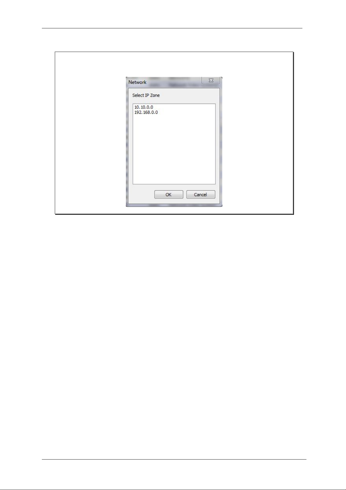
Note: If your network has more than one IP address Zone at the same time, the
confirmation window will be displayed as below. You need to choose the one you
are going to use for your IP devices.
28
Page 30
ENVI Series: VT-IPSN16M
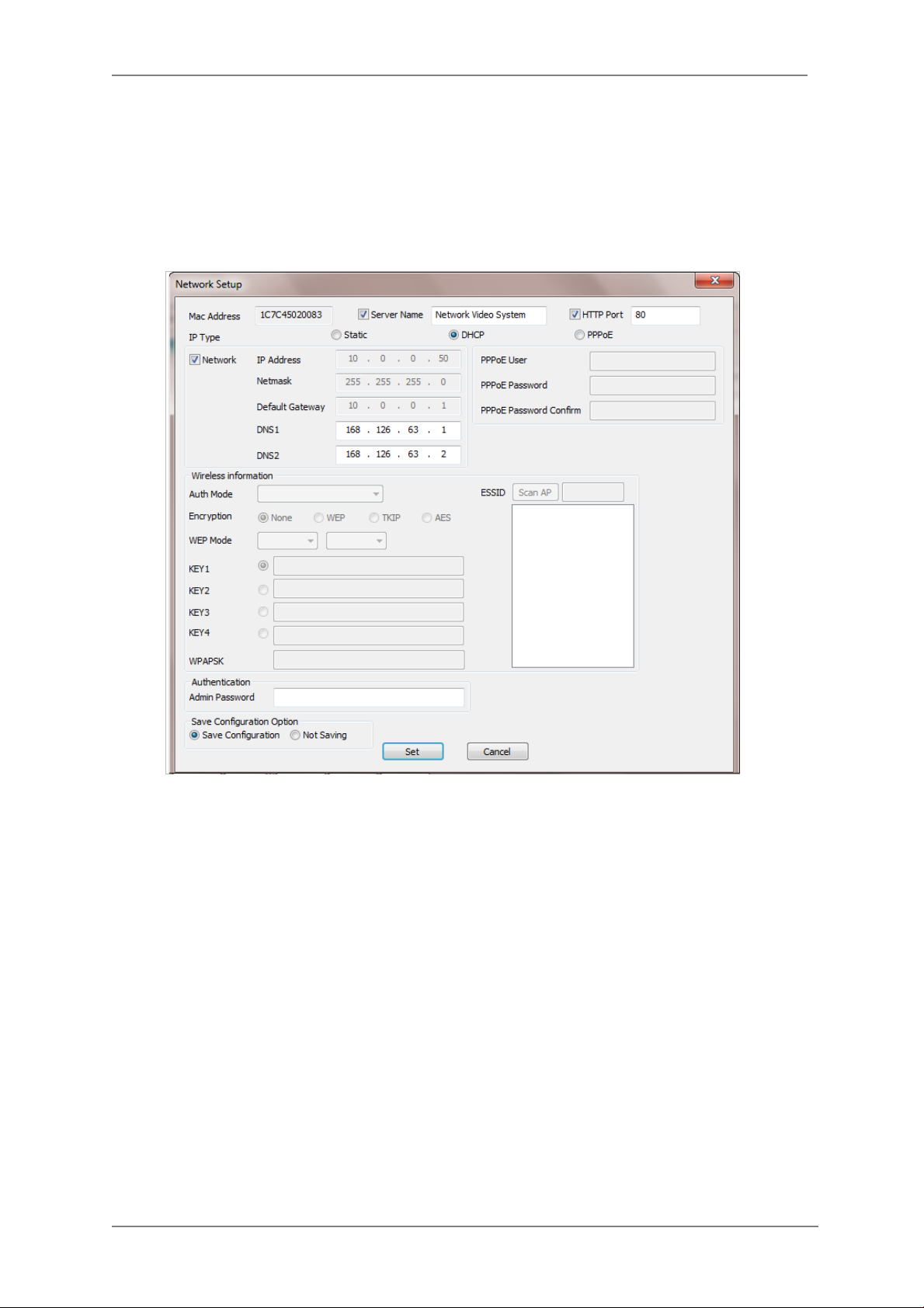
7.5. Using DHCP Server
If your network has a DHCP server runni ng for assigning IP addresses, you may choose to let it
assign IP addresses to the IP devices on the list. To do that, first open the Network Setup window
either by Manual IP Setup or Automatic IP Setup procedure. Choose DHCP in “IP Type”
selection, then IP Address, Netmask, Default Gateway field in Network setup area on the
window will be disabled to input as shown below.
For setting up other fields on the setup window, refer to Section 10.3 Manual Network Setup
on page 24. After filling the fields with appropriate values, click Set button to apply the changed
values to IP device. If you don’t want it, click Cancel button to restore the previous values.
7.6. Using PPPoE
If your network environment is based on PPPoE connection, you’ll need to choose PPPoE on IP
Type selection. Fir st open the Network Setup window either by Manual IP Setup or Automatic
IP Setup procedure. Choose PPPoE in IP Type selection, and then all the fields in Network
setup area on the window will be disabled. The network settings s uch as IP Address, Netmask,
Default Gateway and DNS are no longer available to enter. You only need to enter the Server
Name, HTTP Port num ber, and login authentication for your PPPoE connection.
29
Page 31

ENVI Series: VT-IPSN16M
Section
10.9 Live View on page 34
MAC Address MAC address of the selected device is shown.
Server Name Name of the selected IP device.
HTTP Port HTTP port number of the IP device for web access to homepage.
IP Type How to assign IP address to the device (Select PPPoE in this mode)
User Authentication for PPPoE Connection.
• PPPoE User: Enter User ID.
PPPoE
Authentication
(Admin Password)
Save Configurati on
Option
• PPPoE Password: Enter Password for the User ID.
• PPPoE Password Confirm: Enter the same Password again.
Password for the IP device.
(Default password for Vitek products is “root” unless already changed)
Select whether the configured contents is to be saved in the Camera memory or not.
• Save Configuration: Changed values will be saved in the Camera memory of the
device, which means the changes are permanent.
• Not Saving: Changed values will not be saved in the Camera memory, which
means if the IP device is turned off the changes are lost and the previous setting
will be applied back.
Note: After setting up the network for the IP devices, make sure the IP devices are
accessible on the network from your computer. It can be done by running Live
View function of the homepage of the IP device’s built-in server. Refer to
30
for more information.
Page 32
ENVI Series: VT-IPSN16M
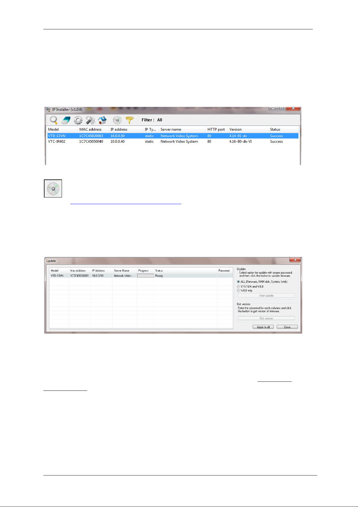
7.7. Updating Firmware
Once IP devices are searched and shown on the screen as functioning successfully, you can update
the firmware of them in IP Installer program. To do that, first check the firmware version of the
device, which you can find on the IP Installer window.
In the above picture, the firmware version of this product is 4.14-01-ds while the latest
firmware version available is 4.16-B0-ds-VI as you could see at Vitek’s homepage
(
http://www.vitekcctv.com/Downloads.asp). If you decide to update the firmware, first
create a folder on your computer for the update firmware, than download the latest firmware to
that folder.
Then select the IP device to be updated on IP Installer window, then click Update Firmware
button from the toolbar. The following window will be displayed.
You may find the Password field is empty on the window shown above. If so, click the Passw ord
field of the IP device and enter the proper password for the device. You are not allowed to update
the firmware if the correct password is not provided.
After the password is entered, the Star t U pdate button will be enabled now. Click the button to
see the following window for selecting the folder where the file has been saved.
folder than click
OK.
Highlight the
31
Page 33
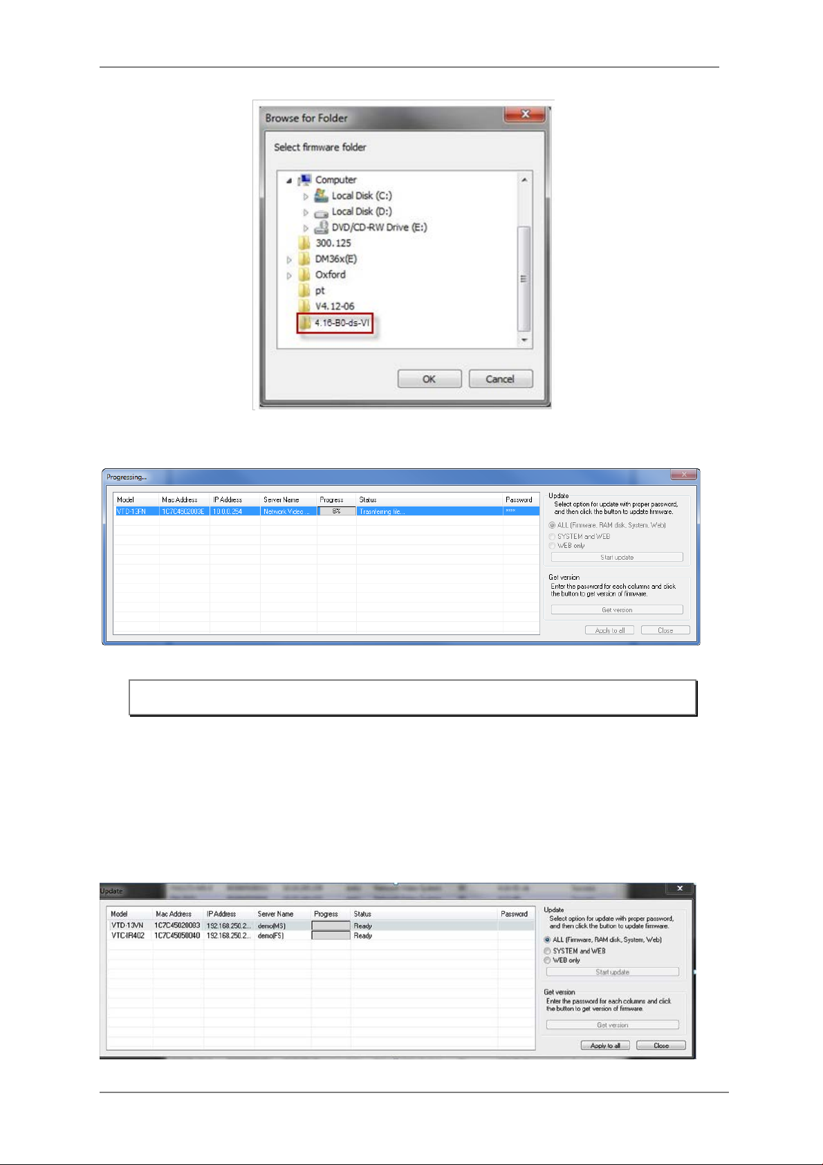
After clicking OK the following window will be displayed.
ENVI Series: VT-IPSN16M
Note: Do not CLOSE window until completed, to avoid permanent damage to the camera.
You can also select multiple IP devices at the same time, and have them start firmware updating in
a single step. Select the files to update by holding CTRL key and selecting which IP devices to
update
Click Start Update button. You will see the update window brought up with multiple IP devices
listed.
32
Page 34
ENVI Series: VT-IPSN16M
The rest of the procedure is the same as in the firmware update case for a single IP device.
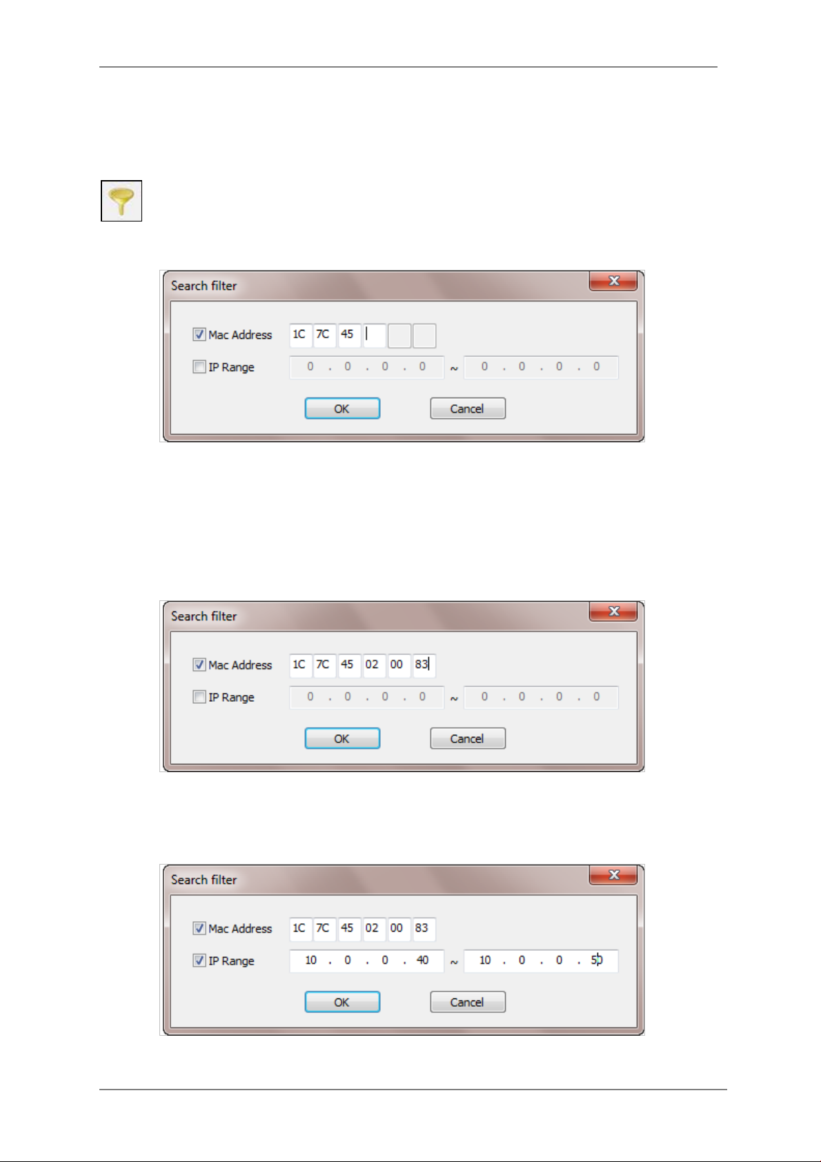
7.8. Filter Configurati on
When you need to search only for the IP device having a specific range of MAC or IP
addresses, you can do it by using this feature. To set the search condition, click Filter
Configuration but ton on the Toolb ar, then the follow ing window will show up on the
screen.
The first six HEX characters are already filled in with 1C:7C :4 5, which is the MAC prefix for Vitek
products. Put a checkmark in MAC Address or IP Range t o set the range for searching.
You can set the range of IP addresses to scan as shown below. In this example, all the IP devices
having MAC address starting with 1C:7C:45 will be listed on the result window after scanning.
Or you can look for a single IP device having a specific IP address as below.
IP Address range for searching can be entered as follows.
You may even set both MAC Address and IP Range together at the same time.
After setting the searching range as explained above, click OK button. Then IP Installer program
33
Page 35
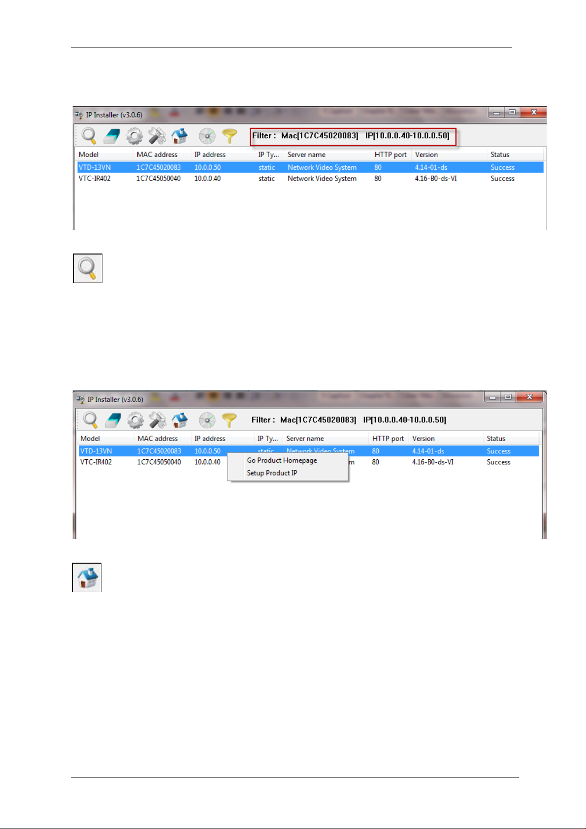
ENVI Series: VT-IPSN16M
window will show the searching range on the top right po rtion of the window as shown below.
To start searching with this condition now, click Search Product button on the toolbar.
The program will start searching and show the result after a moment.
7.9. Live View
Once searching and configuration on IP devices are do ne, you should make sure that the IP
devices are accessible with the new settings. The best way to do it is by connecting to the
homepage of each IP device’s built-in server, and starting Live View feature.
Select Go Product Homepage when you click the right mouse button on the IP device to test.
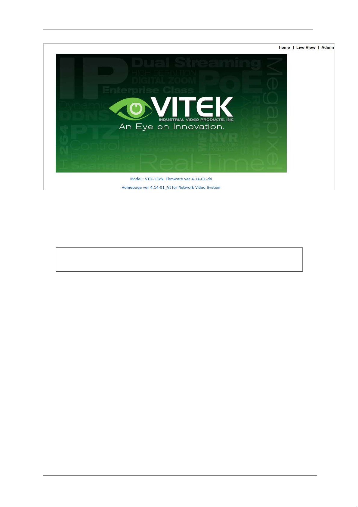
If you select Go Product Homepage, the homepage of that device’s built-in server will
be opened on a new Web browser window as shown below. This is the same result when
you click Connect Product Homepage button from the Main Toolbar.
34
Page 36
ENVI Series: VT-IPSN16M
Click Live View on the top right of the window, then ENVI Series Viewer ActiveX program will be
started. If you have not installed the ENVI Series Viewer program before, it will ask for a
confirmation to install it. Allow it and you will be able to find out whether the configuration by IP
Installer program is properly done.
Note: Refer to
Section 19.
ENVI Series Viewer
on page 79
for detailed information
about the ENVI Series Viewer ActiveX program.
35
Page 37
ENVI Series: VT-IPSN16M
8. ENVI Admin Menu
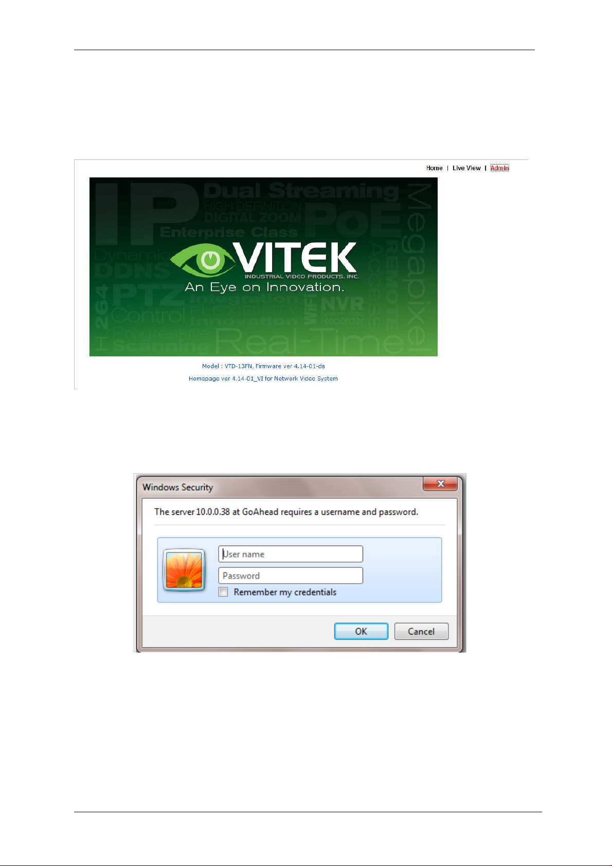
After connecting to a VITEK ENVI Series camera via web browser, you’ll find the web page as
shown below. The upper rightmost item of the menu is Admin; this is where you can set up most
of the features in the VITEK camera you’re connected to.
8.1. Entering Admin Menu
Click Admin then yo u’ll see a login window. In the login window, enter root for both ID and
password as they are the factory defaults. Press Enter key or click OK.
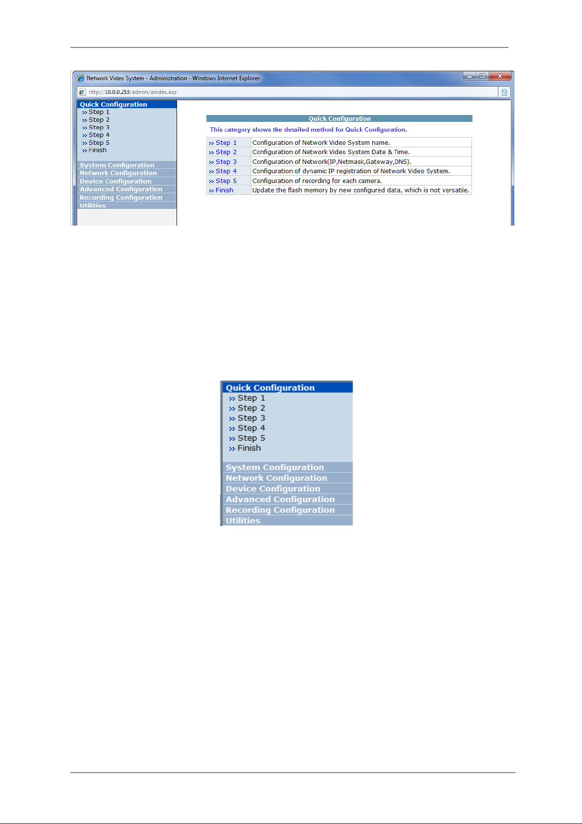
Now the Admin Menu will be displayed as shown below. This will guide you to the top level menu
items, which are Quick, System, Network, Device, Advanced, Recording, and Utilities. Clicking any
of these top level menu items will display submenu ite ms and brief descriptions.
36
Page 38
ENVI Series: VT-IPSN16M
8.2. Admin Menu Structure
The following table shows the hierarchy of the Admin menu structure that we’re going to deal with
in this manual.
9. Quick Configuration
In Quick Configuration, you will be able to set up many of the essential parts of the configuration
in a simple manner without going into details. Selecting Quick Configuration gives you the menu as
seen below. You can perform each setup by clicking the one you would like to configure.
9.1. Step 1: Changing Server Name
Click Server Name on System Configuration menu, then Server Name Setup windows will be
displayed. Refer to Section 13.1 Server Name Setup on pa ge 38 to see how to change the
server name.
9.2. Step 2: Time Setup
Click Date & Time on System Configuration menu, then the Local Date & Time Configuration
window will be displayed. Refer to Section 13.2 Date & Time on page 39 to see how to set up.
9.3. Step 3: Network Setup
To make a connection to the Internet, it is required to figure out the type of the Internet service
you’re using. Refer to Section 14. Network Configuration on pa ge 42 to see how to set up.
37
Page 39

ENVI Series: VT-IPSN16M
9.4. Step 4: IPCCTVDNS.COM
When VITEK Server is used in a Dynamic IP environment, it is required to utilize IP-CCTV DNS
feature. Refer to Section 36 IP-CCTV DNS Setup on page 141 to see how to set up.
9.5. Step 5: Recording Configuration
Vitek cameras with MicroSD card can be configured for recording options in this section. Refer to
Section 17.2 Recording Configuration wit h microSD card on page 71 to see how to set up
9.6. Finish
After clicking Finish all changes will be saved automat ically to the camera/server
10. System Configuration Menu
When you click on System Configuration item on Admin Menu, the following sub menu will be
displayed.
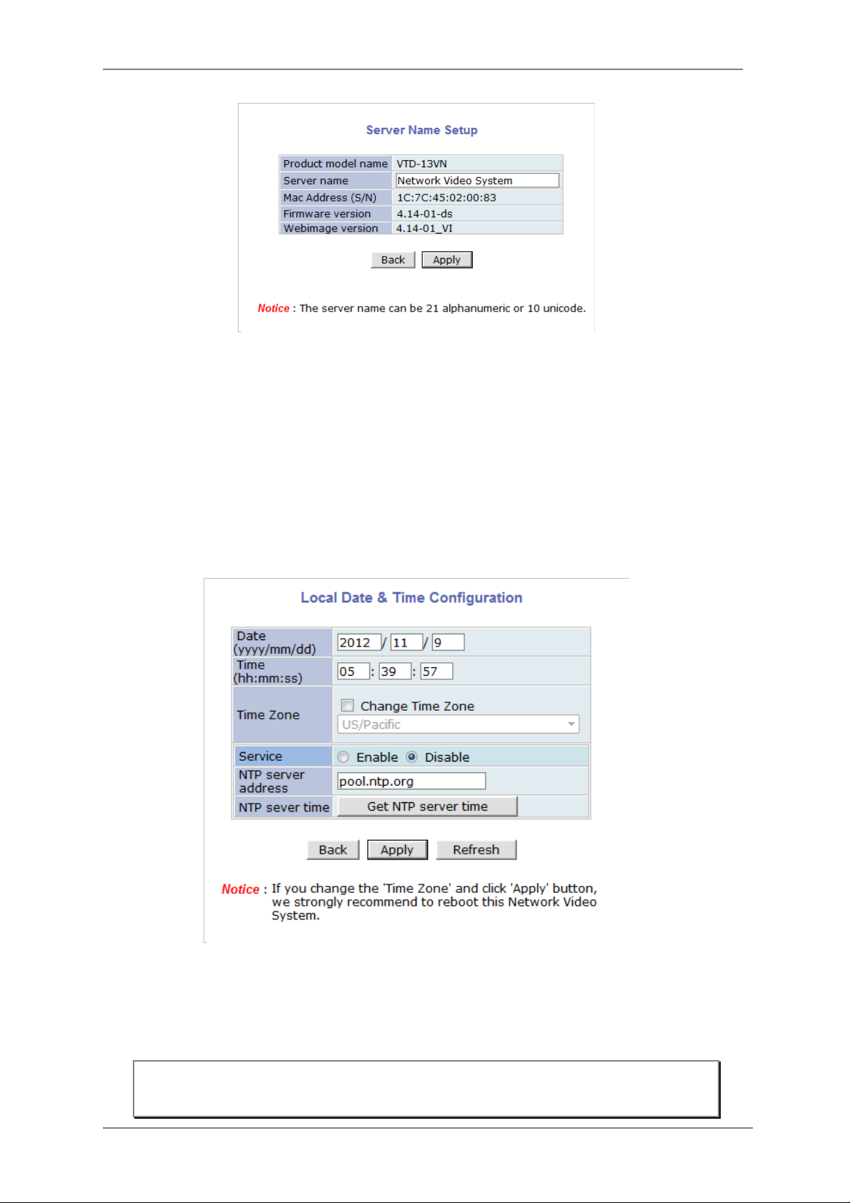
10.1. Server Name Setup
Click Step 1 on Quick Configuratio n or Server Name under System Configuration then the
following will be displayed and you will find out the system information such as model number of
the VITEK camera, server name (camera name), MAC address (serial number), firmware version,
and Web image version.
38
Page 40
ENVI Series: VT-IPSN16M
As an administrator, you can change the name of the camera/ server, but other values are not
allowed to be changed. To change the camera/ server name, enter a new name in the Server
Name field. You may use up to 21 alphanumeric or up to 10 Unicode characters. Tab or any other
special characters are not allowed. Click Apply button to save the setting and it will take effect
immediately.
10.2. Date & Time Click Step 2 on Quick Configuratio n. Or Date & Time under System Configuration Fill the
Date and Time fields with your local time and date information. If you're in a different time zone,
put a checkmark on Change Time Zone, then select the correct region from the dropdown list to
make the time zone change, you need to click Apply button and reboot the system.
If you want to retrieve the exact current time from a NTP server on the network, click Get NTP
Server Time button. Clicking Refresh button will display the date and time retrieved from the
camera. Then click Apply b utton to save it.
Note: In order to retrieve Time and Date information from a NTP ser ver, you need to put
NTP server add ress in advance of setting up, such as pool.ntp.org.
39
Page 41

ENVI Series: VT-IPSN16M
10.3. Admin Password
To change the pass word for the adm inistrator, click Admin Password in System Configuration
menu.
Default ID for adm in account is fixed as “root” and is not allowed to change. In Old Password
field, enter the curr ent password. In both New Password and Confirm Password fields, enter
the same new password. The password must be between 4 and 23 alphanumeric characters. Click
Apply button to put it into effect.
Because you have replaced the password with a new one, the existing network connection made
with old password to VITEK camera is lost now. You will have to reconnect to the VITEK camera
using new password.
10.4. Access Control
Click Access Control on System Configuration menu. The following windows will be displayed.
From the Access Permission window, select either one you would like to use. Click Apply button
to save the change.
• Full Access: Any user can a c c ess the camera/server and use all the features without limits.
• Limited Access: Only registered users can access the camera/server and have limited
privileges.
10.5. User Registration
You can add, modify, or dele te users for your VITEK camera/server here. Once registered as
Limited Access setting, the user can access the VITEK camera/server with some limited privileges.
10.5.1. Add
To add a user, click User Registration on System Configuration menu. When Add is selected,
you can add users a nd define their passwords, names, and access permission le vels respectively.
40
Page 42

ENVI Series: VT-IPSN16M
Enter a User ID between 4 and 23 alphanumeric characters. In both Password and Confirm
Password fields, enter the identical password respecti vely. The password must be between 4 and
23 alphanumeric characters. In Name filed, enter the user’s name up to 23 alphanumeric
characters.
Now select one of the four items from System Resource Access Permission, which defines the
permission level for registered users to the VITEK camera.
• All Channels Access: User can use all the features except for Configuration in Admin Page.
• General Access (only live viewing access): User can only use Live View feature.
• No Access: User is not permitted any of the features.
• Selective Access: User is allowed to use only the selected features. With this item selected,
you can now configure the details und er this menu for the user.
VITEK cameras may have multipl e VS Modules registered in it. When you click on any of the
Enable check boxes, other fields in that row are now enabled to select.
41
Page 43

ENVI Series: VT-IPSN16M
• VS Module ID: VS Module is a network device that has been registered in the VITEK camera
• Camera No.: Among the cameras of the VS Module select one to set up. (between all,1or2)
(
• Alarm Control: Determine if Alarm control is to be allowed.
• Audio Control: Determine if Audio Control is to be allowed. (Feature not available on this model)
After finishing the registration process, click Apply button to add the user.
10.5.2. Edit
To edit a user account, select Edit. In this part, you ca n modify the existing user’s name,
password, and access permission. User ID is not allowed to change. Once selecting a user ID to
edit, the procedure is the same as in Add section.
To see existing users, click Select UserId, and select a user to be edited from the dropdown box.
Then you can change the password, name, or access permission, and click Apply button to save
the setting. Setup o f Access Permission can be done the same way as in the Add section.
Feature not available on this model)
10.5.3. Delete
To delete an existing user, select Delete.
From the list of the users, select a user to delete. Click Delete button to confirm the deletion.
11. Network Configuration
Configuring the netw ork is dependent on how an IP addres s is assigned in Ethernet-based
environment, which is static IP, dynamic IP (DHCP), or PPPoE.
42
Page 44

ENVI Series: VT-IPSN16M
11.1. Static IP Configuration
Select Network Configuration under Network configuration
For static IP, select Static I P and input IP address, NetMask, Gateway, DNS1, DNS2 and click
apply to save settings. After apply, program will ask to close web browser for updates, which will
take 20~30 seconds. If Back button is clicked all values will be discarded. If Refresh button is
clicked, the program will load previous values.
11.2. DHCP Client Configuration To use DHCP a DHCP server must exist in the network environment. Select DHCP Client from
Network Configuration, click Apply. And all information needed will be filled in automatically
43
Page 45

ENVI Series: VT-IPSN16M
11.3. PPPoE Configuration
PPPoE is used to connect VITEK products to a PPPoE modem provided by the ISP. Since PPPoE
needs verification, ID and a password are necessary to access the netw ork. T yp e in PPPoE user ID
and password
11.4. Network Ports
In this configuration, you set up the HTTP port for VITEK cameras to communicate with the Client
PC. HTTP Port is the network port that is used when a Client PC connects to the VITEK camera
Web page. It can be assigned between 80 and 65535.The default value is 80.
Note: If the HTTP port number is changed to a different value than default (80), make
sure the new HTTP port number goes together with th e VITEK cameras IP address.
For example, when a VITEK cameras IP address is 192.168.1.100 and the HTTP
port is 8080, you will have to ent er http://192. 168.1.100:8080 to connect to the
camera.
44
Page 46

ENVI Series: VT-IPSN16M
Section 15.2
on page 53
11.5. Bandwidth Control Co nf igur ation
Bandwidth control is for limiting maximum network traffic. If it is enabled wit h Bandwidth limits,
maximum data size transferred from VITEK cameras won’t exceed bandwidth limits set by users. If
transferred data is exceeded, part of the data will be randomly lost.
If multiple users try to access a VITEK camera when bandwidth control is enabled, users
connected to the VITEK camera will share network bandwidth limit.
Note: This bandwidth control feature works well in M-JPEG video transmission. But, for
H.264, dropping data packets may cause low quality of video, so it is
recommended to utilize CBR and frame rate control instead of bandwidth control
for H.264 video. Refer to
info on CBR and Frame rate
Note: Network Bandwidth control i s managed by the VITEK camera and it drops any data
packets if required, thus you may experience slow connection when this feature
is enabled.
11.6. View Network Status
This menu shows ne twork status of VITEK cameras.
Camera & Motion
For more
45
Page 47

ENVI Series: VT-IPSN16M
11.7. Network Status Notify
This feature helps to send updated network status information to registered email address if any
changes happen. This function will work under DHCP or PPPoE.
If Network Status Notify is set to Enable, VITEK cameras network status will be emailed to a
specific person in case of the following events:
• When it is set to Dynamic IP in the Network Conf iguration menu, and the VITEK camera has
been given a new dynamic IP address and connects to the network.
Or,
• When it is set to PPP Client on WAN-Modem menu, and the VITEK camera has been connected
to the network with ISP or PPP server.
To configure, click Network Status Notify on Network Configu ra ti on menu. The fol low i ng
window will be shown.
46
Page 48
ENVI Series: VT-IPSN16M
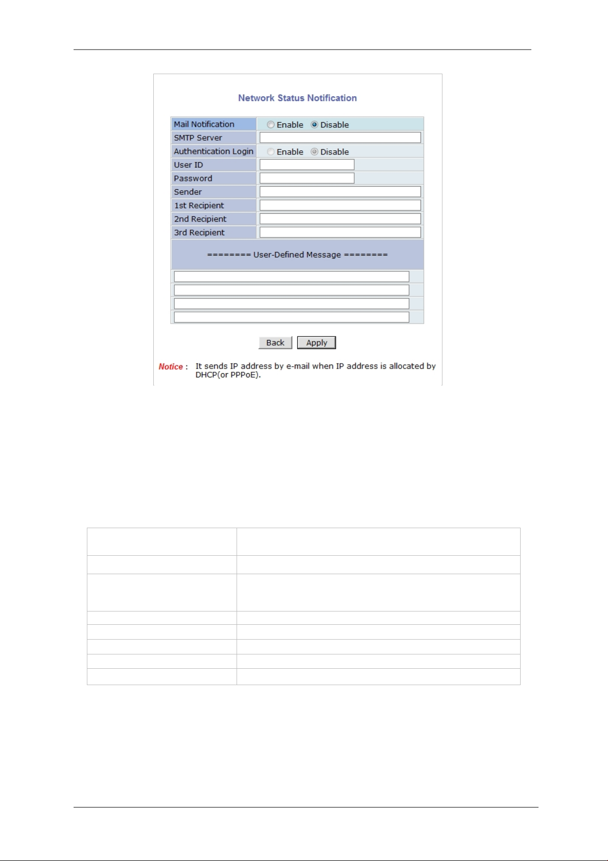
Enable
First, select Enable to use the feature. Then enter the addr ess of the SMTP server which is
needed for email service. If your SMTP server requires a user ID and a password for authentication,
you will have to Enable Authentication Login and enter the user ID and Password.
In Sender field, enter your email address or other meaningful words that will show the message
was sent from the VITEK camera as a notification. Now enter the email addresses of the recipients
in the Recipient fields, up to 3 addresses. In the User-Defin ed Mes s age box, you may enter a
message to explain why the message was sent. After finishing the setup, click Apply to save
settings.
Mail Notification
SMTP Server SMTP Server address for email service
Authentication Login
User ID User ID for SMTP server
Password Password for SMTP server
Sender Email address of Sender or Name
1st / 2nd / 3rd Rec ipient Email Addresses of the Recipients (up to 3 addresses)
User Defined Message Message to be included in the Notification email
Enable: Send email
Disable: Do not send email
: user ID and password are required for SMTP
server
Disable: user ID and password are not required
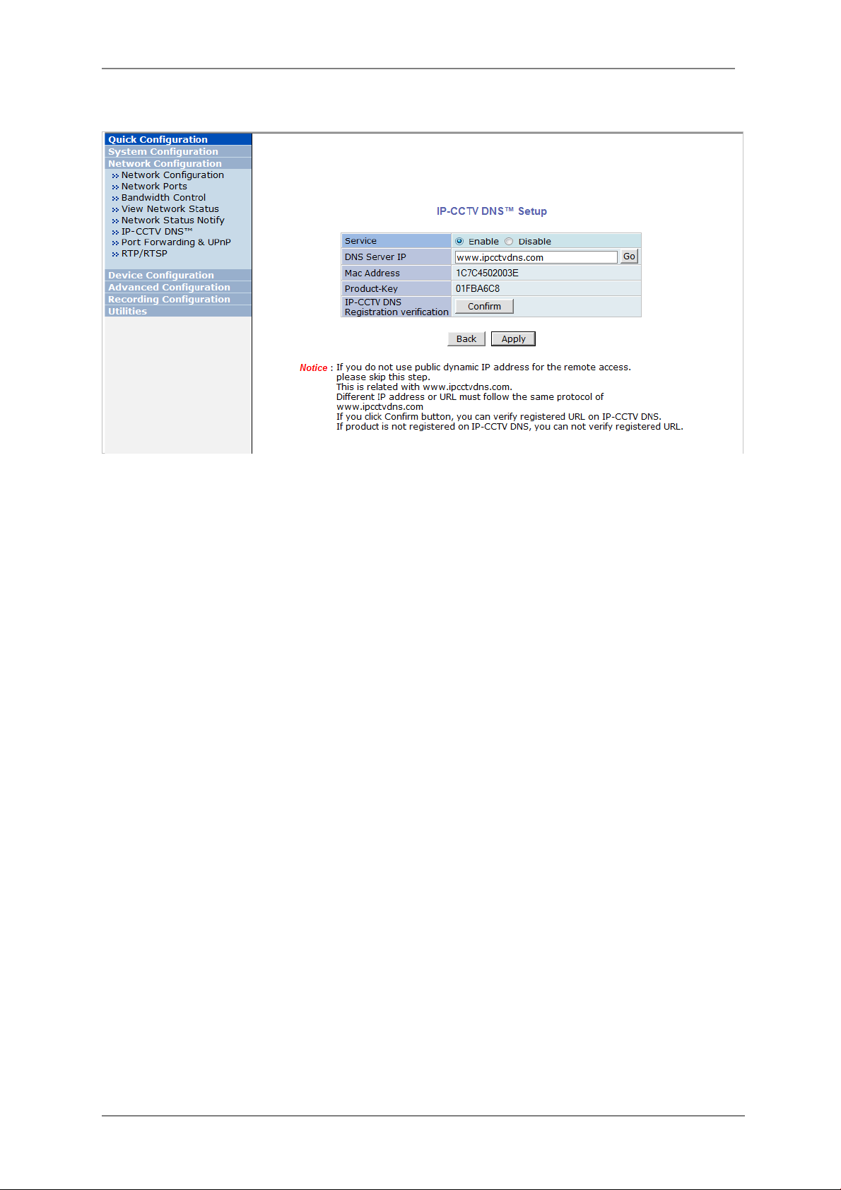
11.8. IP-CCTV DNS Setup
Note: Refer to Section 36 IP-CCTV DNS Registration on page 141 for further details on
configuration
IP- CCTV DNS service provides a static & public domain name to help user’s access VITEK cameras
even though their IP address has changed or they are used in a local network. For proper function
of IP-CCTV DNS service, products need to be accessible through the internet.
47
Page 49
ENVI Series: VT-IPSN16M
.
11.9. Port Forwarding & UPnP
UPnP(Universal Plug and Play)is a kind of network protocol to help users to find and configure
network products in the same local network area. Port forwarding is to assign a certain network
port to a network product so users can access it from outside of the Local Area Network. Generally,
port forwarding can be configured from the network router.
UPnP port forwarding is made up with finding an availa b le network port, assigning it to a VITEK
camera and reporting overall network configuration of a VITEK camera to IP-CCTV DNS server.
Users have to register products into IPCCTVDNS server and IP-CCTV DNS service should be
enabled.
There are 3 options in UPnP Port Forwarding.
• Manual: User Assigned Port issued when users can access network router (hub) and
manually assign available network ports to VITEK cameras. In this case, users have to type
already-assigned network ports under User Assigned port.
• UPnP: User Assigned Port is used when users want VITEK cameras to configure port
forwarding of network hub with user-assigned network port. If it fails, try to change userassigned port
• UPnP: Auto Selected Port is used to let VITEK cameras deal with all network configurations
automatically.
Please note that the network router needs to support UPnP Port Forwarding. There is a limit for the
maximum number of UPnP devices. If it is properly configured, results will be displayed under
UPnP status.
48
Page 50

ENVI Series: VT-IPSN16M
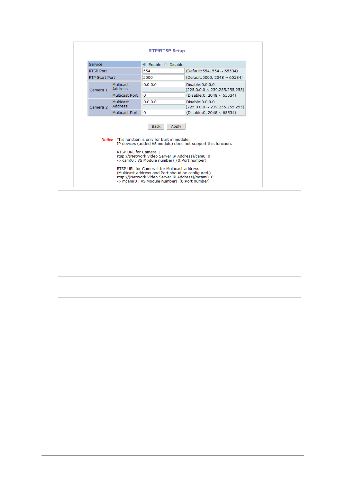
11.10. RTP/RT SP Set up Factory default is Enable to be used with other manufactures VMS software’s
RTSP (Real-Time Streaming Protocol) is a protocol to transfer video and audio streams over the
network. Any application supporting Standard RTSP can be used for VITEK cameras. Quick Time
Player or VLC program can be used with this; it may not be supported in the environment within a
firewall. There are two types of usage; one for Unicast address condition and the other for
Multicast address condition.
For Unicast Address:
Use “rtsp://network video server ip address/cam0_0”. If there are multiple channels, use
cam0_x, x (0~3) with each number applied. If there are multiple modules, use camx_0 x (0 ~ 3)
with each module number applied.
For Multicast Address:
Use “rtsp://network video server ip address/mcam0_0”. If there are multiple channels, use
mcam0_x, x (0~3) with each channel number applied. If there are multiple modules, use mcamx_0
x (0 ~ 3) with eac h module number applied.
49
Page 51
ENVI Series: VT-IPSN16M
In normal case, use default port number 554 to connect to RTSP service.
Service
RTSP Port
RTP Start Port
Multicast
Address
Multicast Port Port number for viewing the video with a multicast address
Enable: Start RTSP service
Disable: Stop RTSP service
If not using port 554, enter the port number you want to use.
e.g.) port number 445==>rtsp:// network video server ip
address:445/cam0_0
The starting number of the port for video transfer. Each time video
transfer connection is made, the port number also increases.
Address for multicast video transfer.
The multicast address 0.0.0.0 is for stopping multicast.
50
Page 52
ENVI Series: VT-IPSN16M
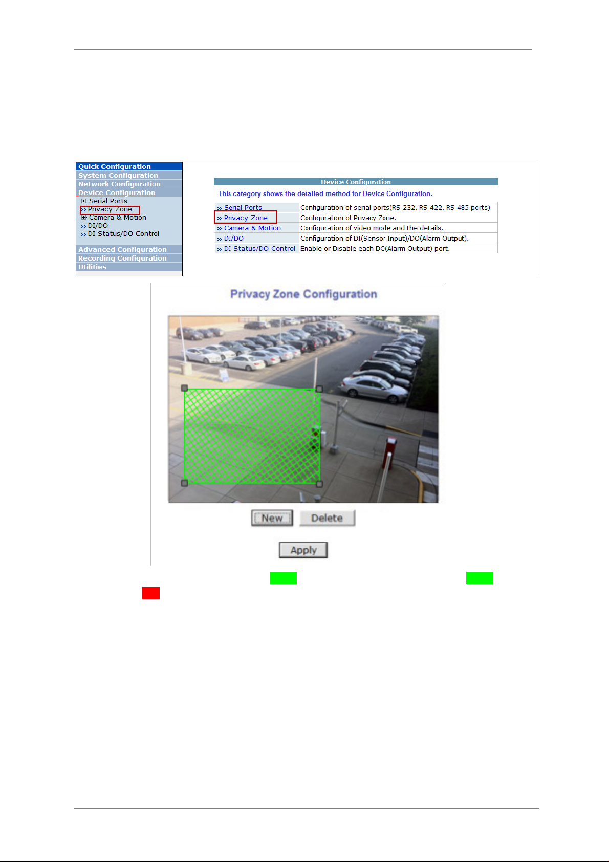
12. Device Configuratio n
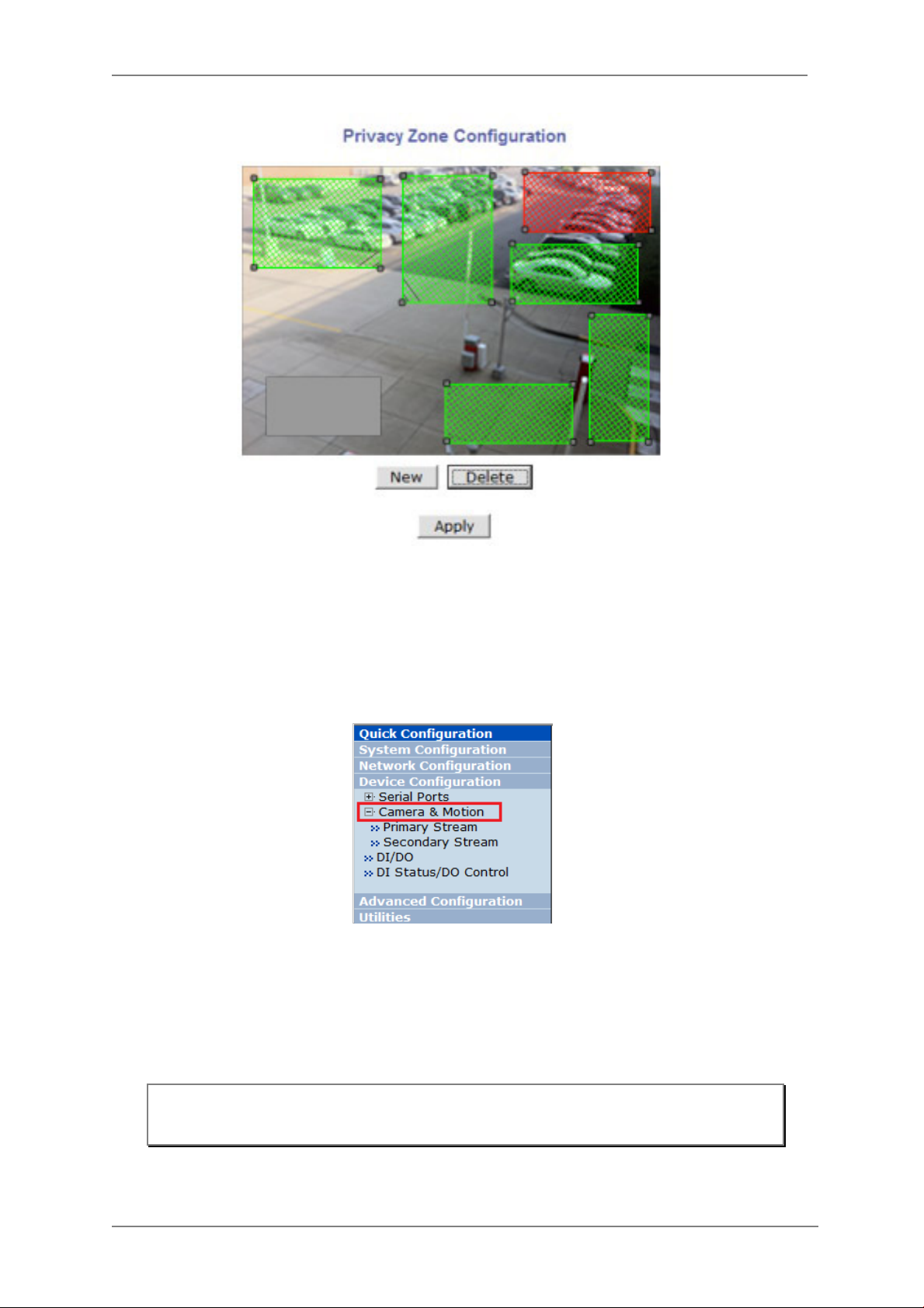
12.1. Privacy Zone
Users can set a privacy zone if a certain part of the screen needs to be unmonitored.
To set the region, click Privacy Zone from Device Configuration category.
To Add a Privacy zone click New button, a Green-colored box will appear, click on the Green box
and it will turn Red, at this point you can resize it by clicking and holding any corner and drag to
desired size. To relocate box click and hold anywhere inside the box and drag to desired location.
Click Apply when done
51
Page 53
ENVI Series: VT-IPSN16M
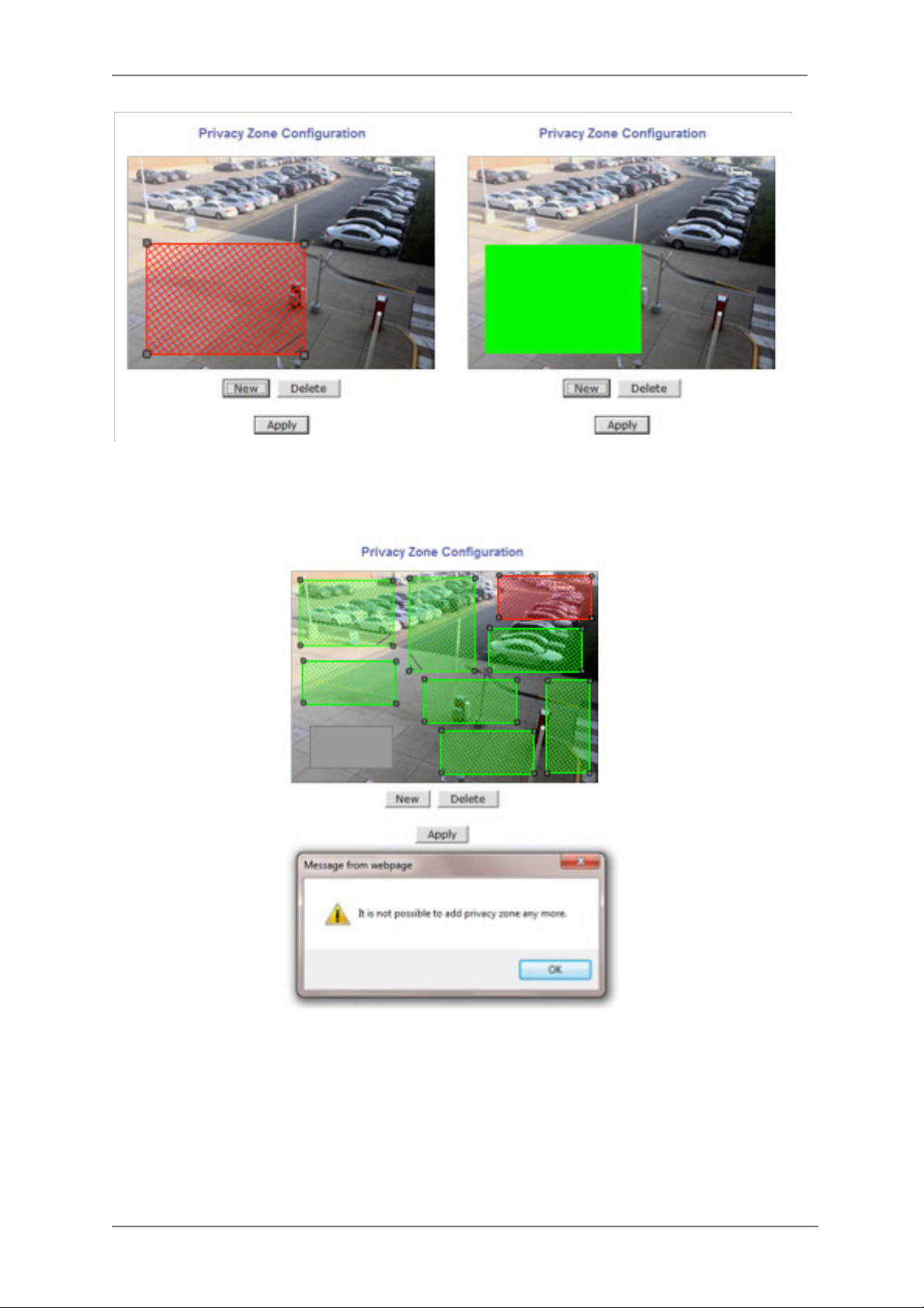
Users can add up to 8 Privacy Zones per screen by repeating above steps. If you add more than 8,
an error message will display on the screen.
To delete a privacy zone, click the zone and click Delete button followed by Apply button.
52
Page 54
ENVI Series: VT-IPSN16M
12.2. Camera & Motion
This menu is used to set up the selection of video format, data added to video data, encoding
speed, audio control, image res ol ut i on, video quality, motion detection, etc.
Click Camera & Motion on Device Co n fi g ur a ti on menu. The configuration menu will be
displayed, and it may be different between VITEK cameras.
• M-JPEG: This format requires much higher network bandwidth than H.264 compression. But
because of its higher quality of still image, it is ade q uate for detailed reviewing of stored video.
• H.264: In this format, each frame data is related to other nearby frames. For this reason, it
provides much higher compression ratio than M-JPEG and is adequate for video transfer.
However, if network conditions are limited dropped frames in video data is possible, the video
quality can be relatively low. With VITEK Cameras, you can set the number of P-frames in the
video which is independent still images between I-frames.
Note: For Dual Stream products, most of the parameters are dependent on primary
stream value.
53
Page 55

ENVI Series: VT-IPSN16M
You can configure the video data format and other information to be contained in it.
• Video with Flexible Extra System data: If Enabled, video data will contain UART sensor
(
data from COM port. .
• Video with user defined message: If Enabled, video data will contain the user-defined
data. (Reserved Field) .
• Video with PPP status: If Enabled, video data will contain PPP connection stat us. .
not available on this model)
• Video with camera name: If Enabled, video data will contain the camera name. .
available on this model)
• Video with server name: If Enabled, video data will contain the server name that you
(
defined. .
• Video with IP address: If Enabled, video data will contain the IP address of the video
server. .
• Audio: (not available on all models) Select if Audio function is to be used (applies to Primary
Stream only). VITEK Cameras provides 2-way audio st reaming by combining microphone input
with video data. Users can listen to the streamed audio through a PC and speakers.
• Frame Rate: For Primary Stream, this is the number of frames compressed in every second.
You can control the network traffic with this parameter. For Secondary Stream, it can be set to a
manner of 1/2, 1/4, 1/8... of the p rimary stream.
• Image Size: Select the resolution of each channel’s video
• Encoding Standard: Select the compression method of each video, either M-JP EG or H.264
format. It is not allowed to set both channels to M-JPEG.
Below is the table of images sizes. To save the setting, click Apply button
Feature not available on this model)
(
Feature not available on this model)
Feature not available on this model)
(
Feature not available on this model)
(
Feature
(
Feature not
54
Page 56
ENVI Series: VT-IPSN16M
Rate Control Mode: CBR (Constant Bit
Video Format SXGA D1 CIF QCIF
NTSC - 704 x 480 352 x 240 160 x 112
PAL - 704 x 576 352 x 288 160 x 144
VGA - 640 x 480 320 x 240 160 x 112
1.3M Pixel 1280 x 1024 640 x 480 320 x 240 160 x 112
2.0M Pixel 1920 x 1080 640 x 480 320 x 240 160 x 112
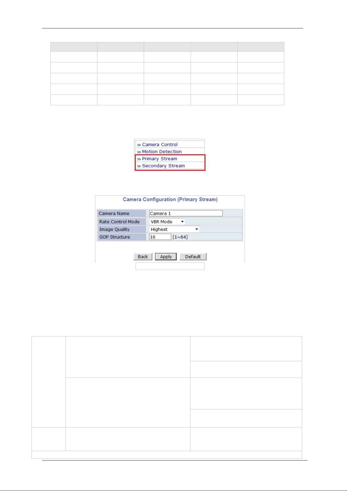
12.2.1. Camera Configuration
On the lower part of Camera & Motion Configuration menu, select a channel to configure.
In the example shown below, Primary Stream is set to H.264 for compression format. Enter
detailed parameters of the camera selected here.
• Camera Name: Enter the name of the channel up to 21 alphanumeric or up to 10 Unicode
characters.
Rate Control Mode
Rate Control Mode: VBR (Variable Bit Rate)
Video frames are encoded with selected
image quality and GOP. Encoded frames have
different data size from each other.
H.264
Rate)
Video frames are encoded with selected
image quality and GOP. Encoded frames have
the same data size as other frames. Due to
the constant bit rate, it has better stable
transmission performance.
M-JPEG -
55
Primary Stream of (H.264)
Image Quality: one of 6 quality levels
(Low Compression / Highest /High
Normal / Low / Lowest)
GOP Structure: Distance between IFrames. That is filled with P-frames.
Bit Rate Control: Total number of Bits
encoded per second. The higher Bit
Rate, the better image quality. Can be
set between 32kbps and 2Mbps.
GOP: Distance between I-Frames. That
is filled with P-frames.
Image Quality: one of 6 quality levels
(Low Compression / Highest / High
Normal / Low / Lowest)
Page 57
ENVI Series: VT-IPSN16M
Image Quality Setup
In Image Quality level setup, select “Low Compression” for higher image quality, but it requires
higher network bandwidth. Selecti ng the “Lowest” requires lower network bandwidth, but gives
decreased image quality.
After configuration is finished, click Apply button to save the setting. If you click Default button,
the entire configuration will be reset to the original values.
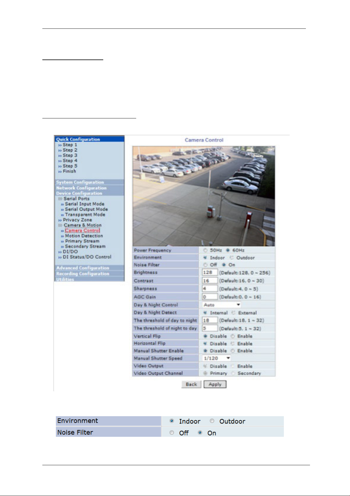
Camera Contr o l (Select Models)
Select Camera Control on the bottom of Camera & Moti on Conf iguration menu.
• Power Frequency: Select NTSC (60Hz) or PAL (50Hz) according to the region.
• Environment: Indoor or Outdoor
• Noise Filter: To reduce static on image
• Brightness: Select the brightness of image between 0 and 256.
• Contrast: Select the contrast of image between 0 and 30.
56
Page 58

ENVI Series: VT-IPSN16M
• Sharpness: select the sharpness of image between 0 and 5.
• Day & Night Control: If used, the image will be in Color mode during daytime and
Black & White mode during night time.
Day & Night Control Description
Disable (No Image Conversion)
Black & White Black & White mode
Auto
• Day & Night Detect:
Day & Night Detect Description
Internal Use Built-in Day & Night feature (Default )
External For use with cameras having IR
• The threshold of day to night: This is the point of transition from Day to Night mode. Select
between 1 and 32, and lower the value the earlier the transition point.
• The threshold of night to day: This is the point of transition from night to day mode. Select
between 1 and 32, and lower the value the earlier the transition point.
• Vertical Flip: this is to rotate the image 180° Vertically
• Horizontal Flip: this is to rotate the image 180° Horizontally
• Manual Shutter Enable: If enabled, the shutter speed will be selected manually. If disabled, it
is controlled automatically.
• Manual shutter Speed: available only when Manual Shutter is Enable Select the shutter
speed of camera between 1/30 a nd 1/24000.
• Video Output: Video output (NTSC/PAL) is enabled.
After all the settings are done, click Apply button to save it. If Default button is clicked, all the
fields return back to original value.
Daytime: Color Mode
Night time: Black & White mode
Motion Detection
57
Page 59

ENVI Series: VT-IPSN16M
• Motion Detection: (this is only available in Primary Strea m) If enabled, Motion Detection
feature is activated and user can configure the areas where motion detect ion function will work.
Click Check All button for whole scene to be active (grid will turn Green) then click on any box
inside scene to take out that area from Motion Detection (box will turn Red) then click Apply to
save
• Motion Sensitivity: Set the sensitivity of motion defined in Motion Detection Area. Select
between -100 and 100. 100 is the most sensit ive.
After all the settings are done, click Apply button to save it. If Default button is clicked, all the
fields return back to original value.
DI/DO Control
Not Available on VTD-MV series
58
Page 60

ENVI Series: VT-IPSN16M
13. Advanced Configuration
There are two types of advanced service, one is Buffered Service and the other is Periodic
Service. In Buffering Service, a series of images are continuously being stored in a buffer memory
of the camera/server for a certain period of time. When the camera/server is triggered by an event
or schedule, the images or alarm stat us just before and after the event/schedule are reported to
you by email or buffered FTP services.
In Periodic Service, only the image, alarm/sensor status after an event/schedule is reported to you
upon the server being triggered.
59
Page 61

ENVI Series: VT-IPSN16M
13.1. Advanced Services
Pre-Alarm buffer size and buffering speed can be defined here.
• Pre-Alarm Buffer Size: You can set the buffer size which will store the images before event.
The unit is in frame, and each channel can be set with different values. The total number of
frames for Pre-Alarm Buffer and Post-Alarm Buffer is limited to 10 fra mes.
• Pre-Alarm Speed: You can set the buffering speed. If it’s set to Fastest, the server will store
images as fast as it can. Each cannel can be set with different values.
This configuration applies to E-mail and FTP (Buffered), and click Save button to apply changes.
• E-mail: Set up Email Service configuration
• FTP (Buffered): Set up FTP (Buffered) Service configuration
• FTP (Periodic): Set up FTP (Periodic) Service configuration
60
Page 62

ENVI Series: VT-IPSN16M
Item
Description
13.1.1. E-mail Service Configuration
Email configuration is set up here for Alarm in case any event occurs.
Camera 1~2 Select a channel to be configured for email notification
Service Select Enable in order to use this service
SMTP server address Enter SMTP server’s address for sending email.
Authentication Login Select Enable if SMTP server requires ID and password
User ID Enter User ID to log in to SMTP server
Password Enter Password to log in to SMTP server
Sender Enter email address of the sender
1st Recipient Enter the email address of the first recipient
2nd Recipient Enter the email address of the second recipient
3rd Recipient Enter the email address of the third recipient
Click Save button to apply the change. If you don’t want to change, click Back button.
61
Page 63

ENVI Series: VT-IPSN16M
E-mail Service Setup for Each Channel
For each channel, the following items can be configured for email service: Condition, Post-Alarm
Buffer Size, and Post-Alarm speed. The content of text message and display style of DI value can
be configured as well.
Item Description
Condition 1 ~
Condition 3
Pre-Alarm Buffer Size The Buf fer siz e assigned for Pre-Alarm.
Check Video buffer Click this link to go to Advanced Services for buffer setup.
Pre-Alarm Images The number of image frames to store before Alarm
Post-Alarm Images The number of image frames to store after Alarm
Pre-Alarm Speed
Post-Alarm Speed Select the speed of Post-Alarm. Fastest is the highest value.
Subject Subject of the E-mail message to send.
1 Content of the first line in the email message.
2 Content of the second line in the email message.
3 Content of the third line in the email message.
4 Content of the fourth line in the email message
Value Format
Select a condition for Email service to be activated.
This field shows the speed of Pre-Alarm. Configuration can be
done in Advances Services page.
Select the format for the Event or DI data to email.
NONE: Don’t Send, INT: Decimal, HEX: Hexadecimal,
BIN: Binary, IPA: IP Address, EVT: Name of Event
62
Page 64
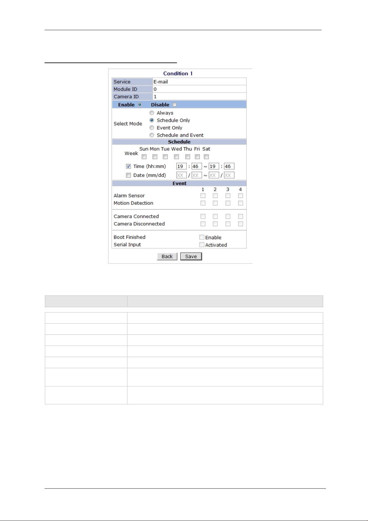
ENVI Series: VT-IPSN16M
Item
Description
After finishing setup, click Save button to apply. If you don’t want to change, click Back button.
Condition, Schedule & Event Configuration
If you click on a Condition link, the Advanced Service windows is displayed as shown below.
Alarm Service is activated only when the conditions in Advanced Services are met.
Service This shows what service this condition is for.
Module ID Module ID for current setup
Camera ID Channel ID for current setup
Enable / Disable Select Enable to use Condition, otherwise select Disable.
Always This Condition applies all the time. (Schedule or Event is not usable)
Schedule Only
Event Only
To save the setting, click Save button. If you want to cancel it, click Back.
Use Week, Time, and Date in Condition parameter. If none of the
weekdays are checked, it is activated every day.
It is activated only when any of the following events occurs.
(Sensor, Motion Detection, Camera Connection, Server Booting)
63
Page 65
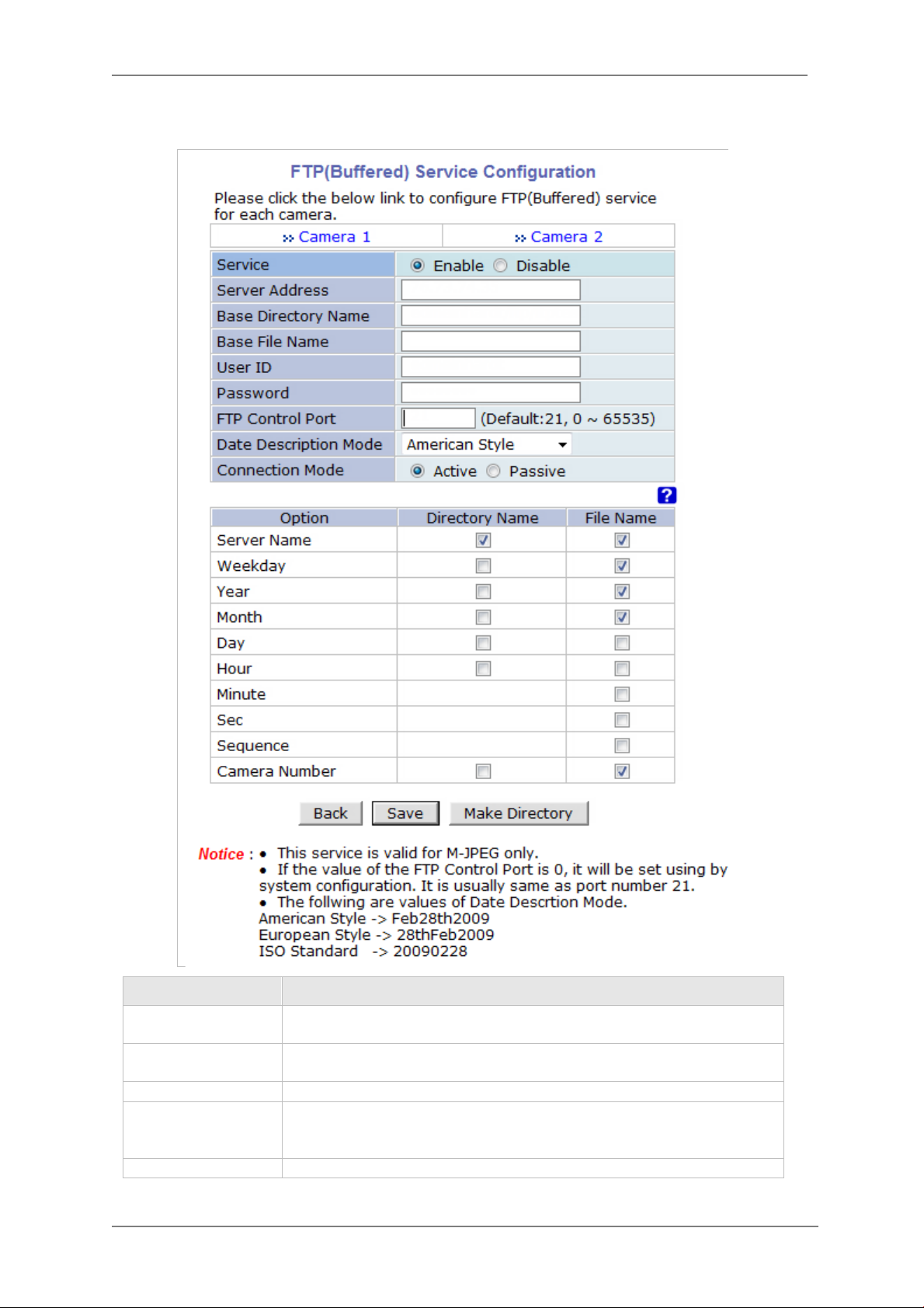
13.1.2. FTP (Buffered) Service Configuration
Item
Description
Enable
Server Address
FTP Server Address.
ENVI Series: VT-IPSN16M
Camera 1 - Camera
2
Service
Base Directory
Name
Base File Name The base file name of the data to be uploaded in FTP server.
64
Select which channel to set up for FTP (Buffered).
Select
Disable.
The directory in FTP server where the data will be uploaded.
(You should make the directory in the FTP server before using the
service.)
to use the FTP (Buffered) service. Otherwise select
Page 66
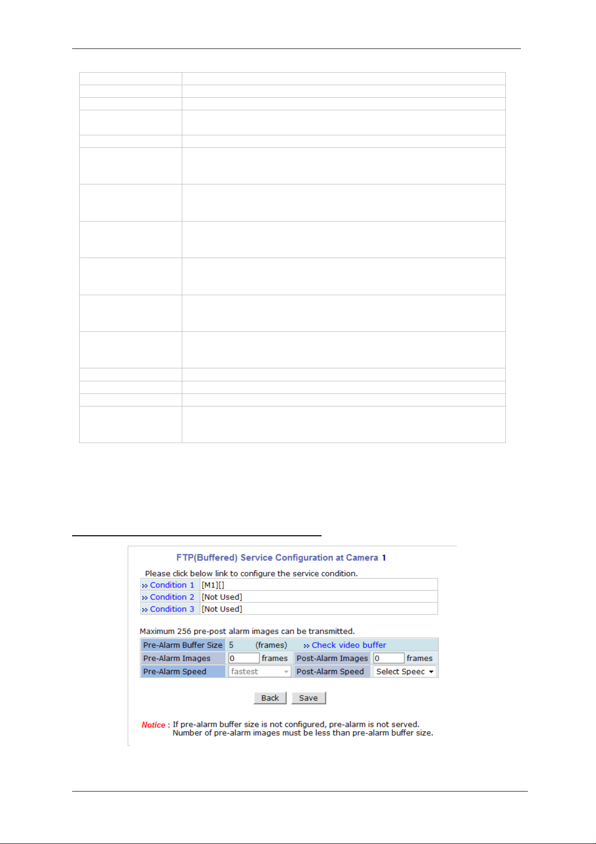
ENVI Series: VT-IPSN16M
Connection Mode
Select connection mode for FTP server
If File Name is checked, new file is created with server name.
Directory Name
If Directory Name is checked, new directory name is created with
Directory Name
If Directory Name is checked, new directory name is created with
Sequence
If checked, new files are created starting from 0, with increment of 1.
User ID Enter a User ID to log in to FTP server.
Password Enter the Password for the user ID to log i n to FTP server
FTP Control Port Port number for FTP server (Normally 21 is used)
Date Description
Mode
Server Name
Select Date Display Style: American, European or ISO Standard
If Directory Name is checked, new directory is created with server
name.
If
Weekday
Year
Month
Day
Hour
Minute If checked, new file name is created with minute.
Sec If checked, new file name is created with second.
Camera Number
To create a dire c tory with the options shown above, click Ma ke D ir ectory button. After finishing
the configuration, click Save button to apply the change and continue to the next page. Clicking
Back button will cancel the changes and go back to the previ ous page. (This service is ava ilable
only in M-JPEG mode.)
weekday.
If File Name is checked, new file name is created with weekday.
Year.
If File Name is checked, new file name is created with Year.
If Directory Name is checked, new directory name is created with
month.
If File Name is checked, new file name is created with month.
If
day.
If File Name is checked, new file name is created with day.
hour.
If File Name is checked, new file name is created with hour.
If Directory Name is checked, new directory is created with camera
number.
If File Name is checked, new file is created with camera number.
is checked, new directory name is created with
is checked, new directory name is created with
FTP (Buffered) Service Configuration at Camera 1
65
Page 67
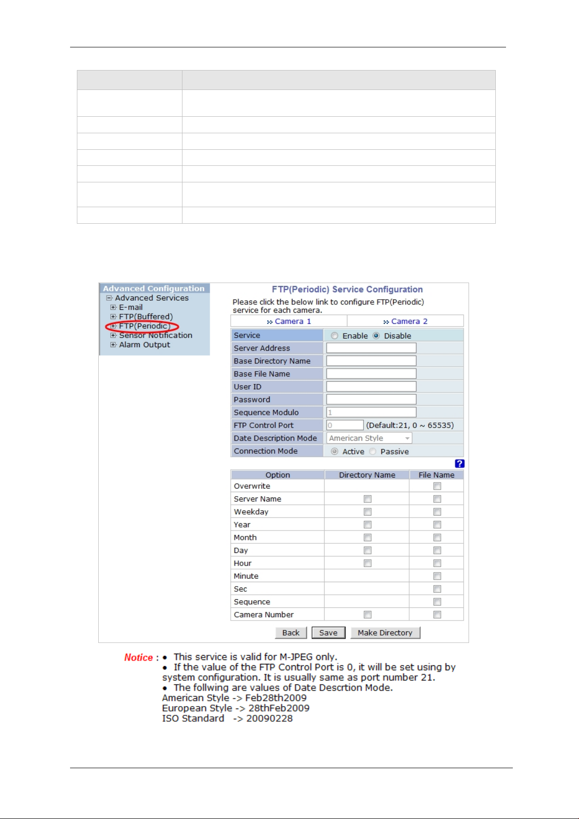
Item Description
ENVI Series: VT-IPSN16M
Condition 1 ~
Condition 3
Pre-Alarm Buffer Size The Buffer size assigned for Pre-Alarm.
Check Video buffer Click this link to go to Advanced Services for video buffer setup.
Pre-Alarm Images The number of image frames to store before Alarm.
Post-Alarm Images The number of image frames to store after Alarm.
Pre-Alarm Speed
Post-Alarm Speed Select the speed of Post-Alarm. Fastest is the highest value.
After finishing setup, click Save button to apply. If you don’t want to change, click Back button.
13.1.3. FTP (Periodic) Service Configuration
Select a condition for FTP (Buffered) service to be activated. Up to 3
conditions can be set.
This field shows the speed of Pre-Alarm. Configuration can be done in
Advances Services page.
66
Page 68

ENVI Series: VT-IPSN16M
If File Name is checked, new file name is created with weekday.
Directory Name
If Directory Name is checked, new directory name is created with
Directory Name
If checked, new files are created starting from 0, with increment of
Item Description
Camera 1 - Camera 2 Select which channel to set up for FTP (Periodic) service
Service
Server Address FTP Server Address.
Base Directory Name
Base File Name The base file name of the data to be uploaded in FTP server.
User ID Enter a User ID to log in to FTP server.
Password Enter the Password for the user ID to log in to FTP server
Sequence Modulo Maximum number used in sequential file name
FTP Control Port Port number for FTP server (Normally 21 is used)
Date Description
Mode
Connection Mode Select connection mode for FTP server
Select Enable to use the FTP (Periodic) service. Otherwise select
Disable.
The directory in FTP server where the data will be uploaded.
(You should make the directory in the FTP server before using the
service.)
Select Date Display Style: American, Euro pean or ISO Standard
Overwrite If checked, new file overwrites the existing file with the same name.
If Directory Name is checked , new directory is created with server
Server Name
Weekday
Year
Month
Day
Hour
Minute If checked, new file name is created with minute.
Sec If checked, new file name is created with second.
Sequence
Camera Number
To create a dire c tory with the options shown above, click Ma ke D ir ectory button. After finishing
the configuration, click Save button to apply the change and continue to the next page. Clicking
Back button will cancel the changes and go back to the previ ous page. (This service is available
only in M-JPEG mode.)
name.
If File Name is checked, new file is created with server name.
If Directory Name is checked, new directory name is created with
weekday.
If
year.
If File Name is checked, new file name is created with year.
month.
If File Name is checked, new file name is created with month.
If Directory Name is checked, new directory name is created with
day.
If File Name is checked, new file name is created with day.
If
hour.
If File Name is checked, new file name is created with hour.
1.
If Directory Name is checked, new directory is created with camera
number.
If File Name is checked, new file is created with camera number.
is checked, new directory name is created with
is checked, new directory name is created with
67
Page 69
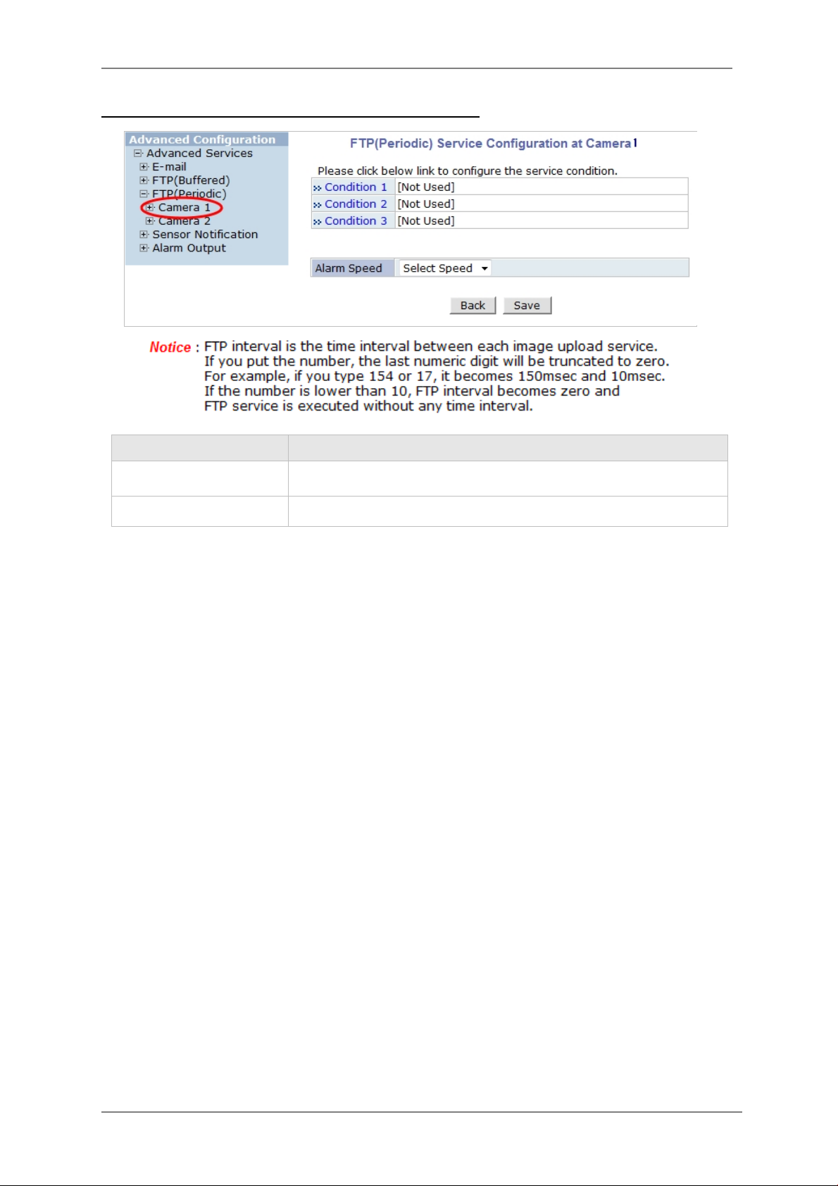
FTP (Periodic) Service Configuration for each channel
Item
Description
Select a condition for FTP (Periodic) service to be activated. Up to 3
ENVI Series: VT-IPSN16M
Condition 1 ~ Condition 3
FTP interval (msec) Select the speed of images to send in FTP(Periodic) service
After finishing setup, click Save button to apply. If you don’t want to change, click Back button.
conditions can be set respectively.
14. Recording Configuration for Cameras with microSD card
Some versions of VITEK IP cameras will have a microSD card slots on the back.
Those models can record and playback video from the microSD card if installed. Vitek IP cameras
can
Support cards up to a 32GB. (Only use quality class 10 microSD cards)
14.1. MicroSD Configura ti on
If a microSD card (SD card) is not present in the slot already, power down the VITEK IP camera
before inserting an SD card. Make sure to turn the power on after i nserting the SD card. Open a
web browser, type in the IP address of the VITEK camera. Log in as Admin, Enter Recording
Configuration menu, and the n click on SD Configuration then click on SD Information, the
card’s format information will be displayed
68
Page 70
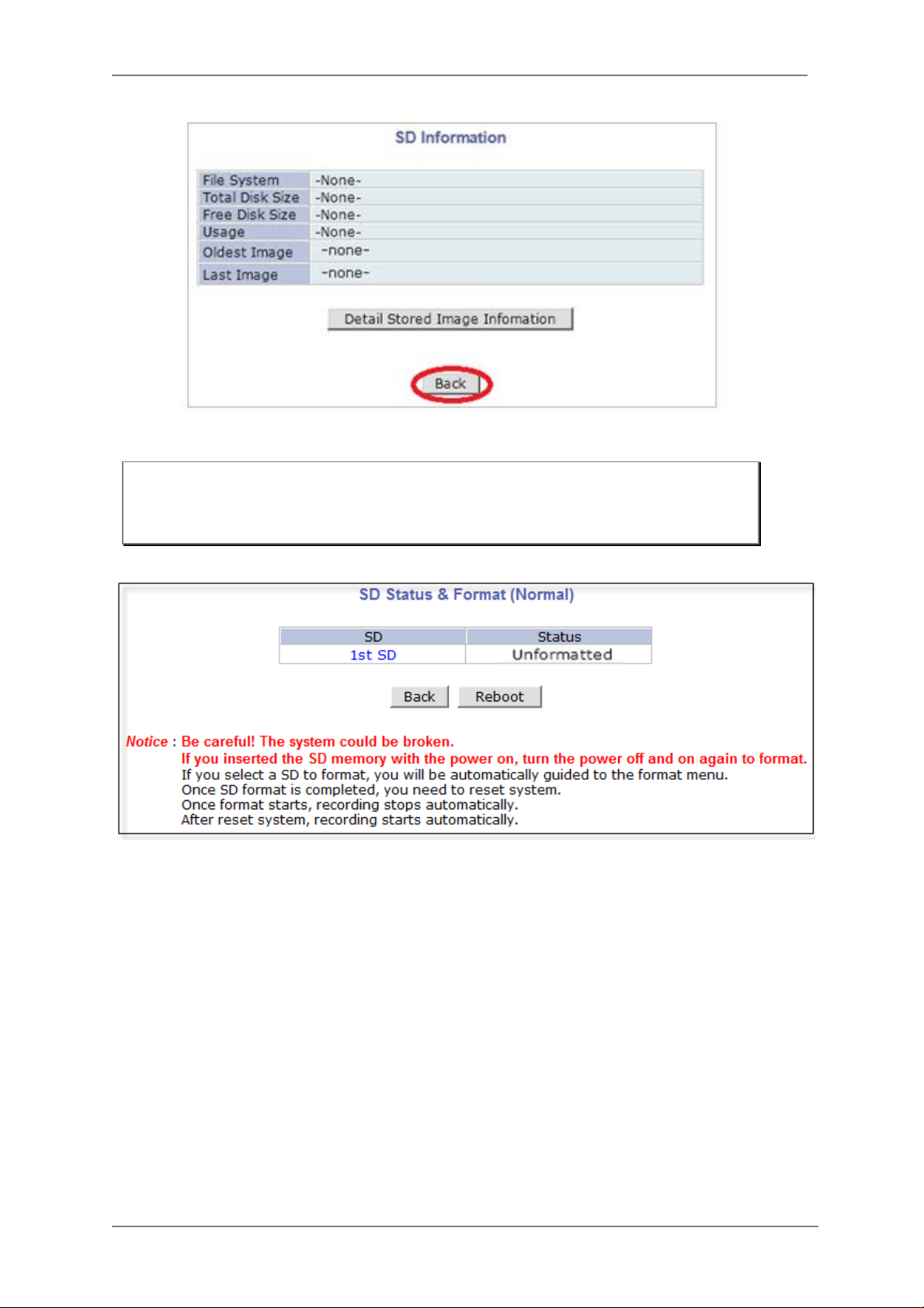
ENVI Series: VT-IPSN16M
If entire SD information is showing “-NONE-” this means SD card is not forma tted, in this case click
Note: Be sure to turn off the device before installing a SD card. Otherwise, the SD card
may become defective. Always check the recommended type of SD card because
non-conforming SD cards can cause abnormal behavior of the system.
back button followed by clicking SD Status & Format
Click on “1
st
SD” and the following screen will be displayed
69
Page 71
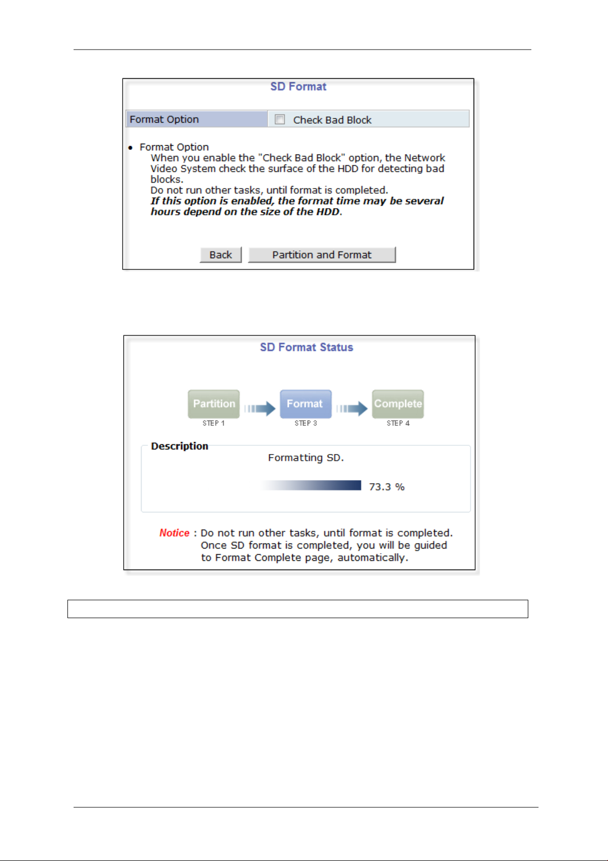
ENVI Series: VT-IPSN16M
Read format option on screen and then click Partition and Format a pop up screen will display
asking if you want to do a “Partition and formatting” click OK to continue or Cancel to stop. After
clicking OK the following screen will be displayed
Note: if program is terminated during the “Format” process SD Card might be damaged
After formatting is completed t he following screen will be displayed
70
Page 72
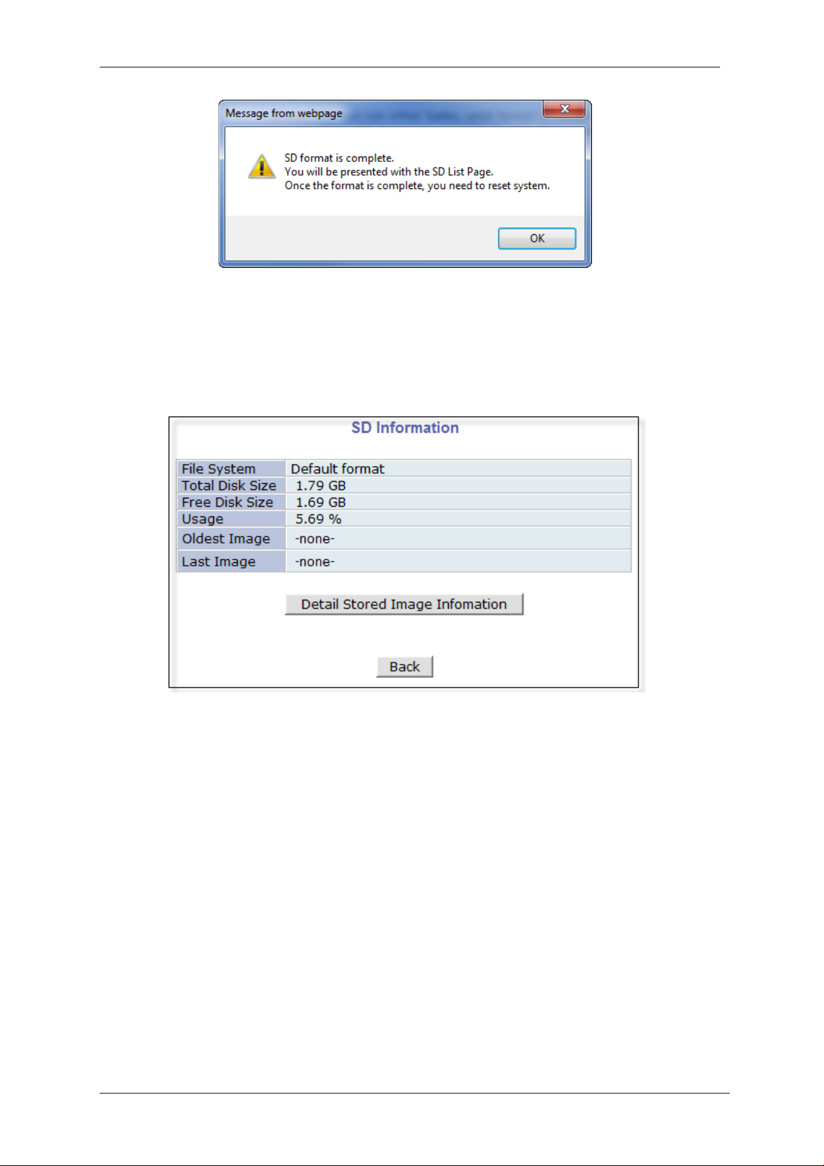
ENVI Series: VT-IPSN16M
Click OK and you will be brought back to the “SD Status & Format screen” click on “Re bo ot”
wait approximately 30 seconds and log back into the Admin screen. Open up “Recording
Configuration” menu and click on “SD Co nf iguration” then click on “SD Information” and the
following screen will be displayed showing SD card info
14.2. Recording Configuration with microSD card
Each camera has 2 streams (referred as Camera 1 / Camera 2 (see image below)) which can be
configured for recording options in this section. Configuration items include motion detection
recording, 24-hour continuous recording, event-driven recording, etc.
You can find out the list of streams (camera 1 / camera 2) with recording capability by clicking
Recording Config ur ation on the left side of your screen. For example, you will see 2
streams (camera 1 / camera 2) from the list of VS Module ID (IP Devices).
71
Page 73
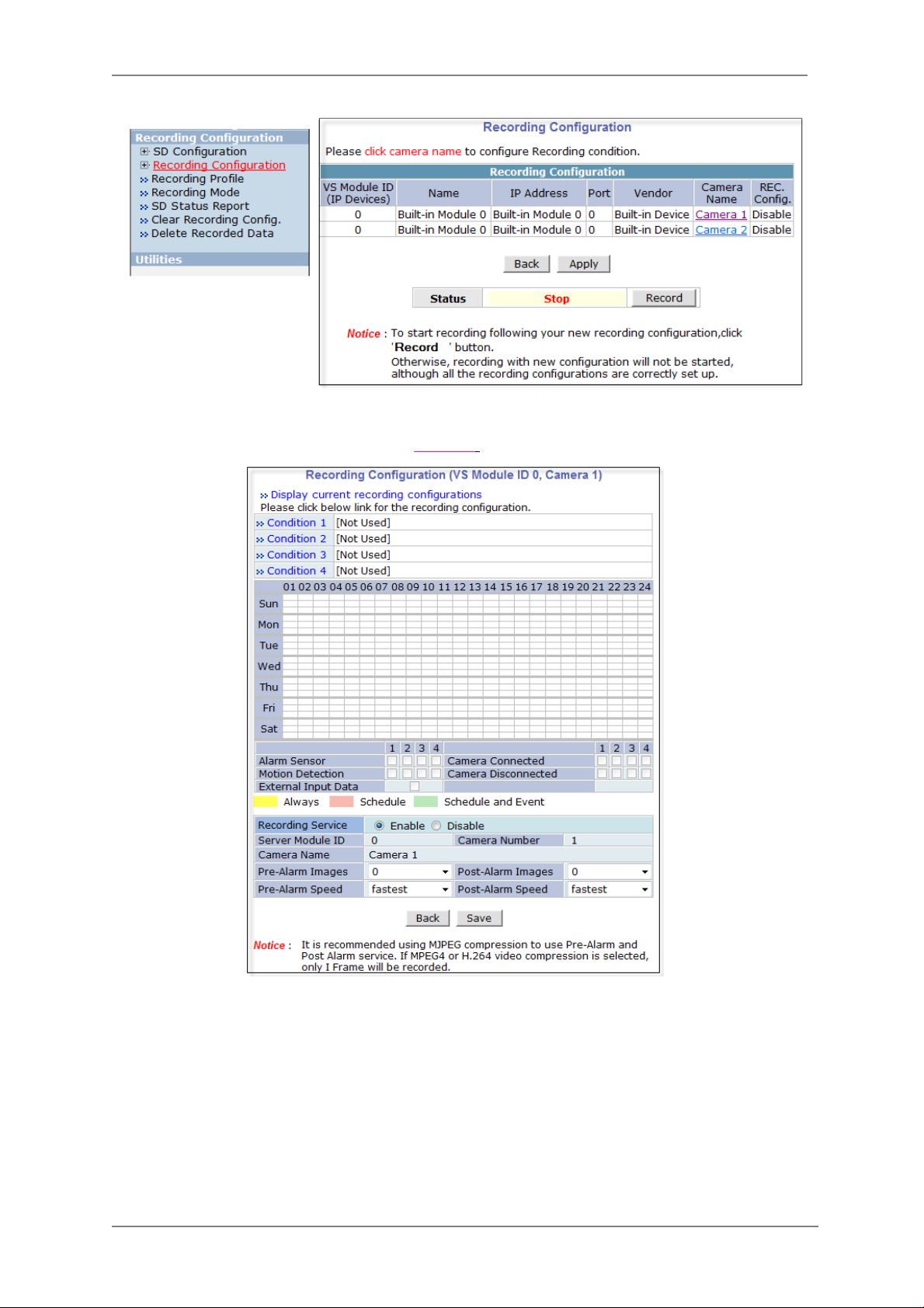
ENVI Series: VT-IPSN16M
Below is an example of configuring the motion detection-triggered recording. It starts by clicking
Recording Configuration and clicking on Camera1,
the following screen will be display.
Select Condition 1and the following window will be display.
72
Page 74

ENVI Series: VT-IPSN16M
Enable / Disable
By clicking on Enable you will be able to select your mode (Always, Schedule only etc). in this
example we will be selecting “Event Only”.
Schedule
Under Schedule you can select time and date for motion recording if left blank motion recording
will be 24hrs, 7 days a week. In this example we will be leaving it blank (24/7).
Event
Under Event click
73
Motion Detection
(stream 1 / stream 2). Click on Save to finish.
Page 75

ENVI Series: VT-IPSN16M
15. Utilities
In Utilities part of the Admin menu, you can view the System Log file, Save Configuration,
Reboot, Factory Default and System Update.
74
Page 76

ENVI Series: VT-IPSN16M
15.1. System Log
System log file provides you the information about when and who access’ the contents of VITEK
Cameras such as HTTP file or CGI programs. In each line, log data consists of date, time, category,
IP address, user ID.
15.2. Save Configuration
VITEK cameras save the configurations afte r every step.
15.3. Reboot
It is recommended to reboot the system after making changes to the configuration. To reboot,
click Reboot on Utilities menu. A screen will display to confirm a system reboot, click ok to
continue.
Windows Internet Explorer will ask to close the webpage, click Yes.
75
Page 77

ENVI Series: VT-IPSN16M
15.4. Factory Default
When required to restore the configuration of a Camera to factory default conditions, Network
configuration is not affected by this action.
Click Factory Default on Utilities menu. A confirmation screen will be displayed as shown Click
Factory Default button, otherwise click Back butto n to cancel it. The second confirmation screen
will appear. Click OK button to restore the factory default condition right away. If you click Cancel,
web browser will go back to the previous screen without any change made.
15.5. System Update ** Is Highly Recommended to Use the IP Installer Program for This Process **
76
Page 78

ENVI Series: VT-IPSN16M
Once IP devices are searched and shown on the screen as functioning successfully, you can update
the firmware of them using the “IP Installer” program. To do that, first check the firmware version
of the device, which you can find on the IP Installe r window.
In the above picture, the firmware version of this product is 4.14-01-ds while the latest
firmware version available is 4.16-B0-ds-VI as you can see at Vitek’s homepage
(
http://www.vitekcctv.com/Downloads.asp). If you decide to update the firmware, first
create a folder on your computer for the update firmware, than download the latest firmware to
that folder.
Then select the IP device to be updated on IP Installer window, then click Update Firmware
button from the toolbar. The following window will be displayed.
77
Page 79

ENVI Series: VT-IPSN16M
Note:
You may find the Password field is empty on the window shown above. If so, click the Passw ord
field of the IP device and enter the proper password for the device. You are not allowed to update
the firmware if the correct password is not provided.
After the password is entered, the Star t Up date button will be enabled now. Click the button to
see the following window for selecting the folder where the file has been saved.
folder than click
OK.
Highlight the
After clicking OK the following window will be displayed.
Do not CLOSE window until completed, to avoid permanent damage to the
camera.
78
Page 80

ENVI Series: VT-IPSN16M
16. ENVI Series Viewer
16.1. Introduction
ENVI Series Viewer is an ActiveX program for Internet Explorer web browser, which enable users
to control video and audio functions of network video devices over the TCP/IP network. ENVI
Series Viewer works with EN-V-R network video software, Vitek Network Video Servers, Network
Video Recorders, and Network Cameras to show real-time live video images and enables users to
control audio, Relay Output, and PTZ functions. (Supported cameras)
16.2. Key Features
Displays live video streams transmitte d from V itek Cameras / Servers
Plays audio transmitted from Vitek Cameras / Servers (supported cameras)
Transmits audio from PC with ENVI Series Viewer to Vitek Camera / Servers
Stores live video screen as image files
Stores live video streams as video files
Controls Relay Output of Vitek Cameras / Servers (supported cameras)
PTZ Controls (supported cameras)
Supports the group mode to see specific channels (for Network Video Recorders only)
Displays live videos in full screen mode
Supports Flexible Extra System
16.3. System Requirement for PC
For best quality and performance, your computer needs to meet the minimum requirement as
below.
OS: Microsoft Windows XP Pro, Wi ndows 7
CPU: Intel Pentium 4, 2 GHz (Dual-Core or faster is recommended)
System RAM: 2GB
Video Card: 256MB Ram, 1024x768 Resolution
100 Mbps Network Adaptor
79
Page 81
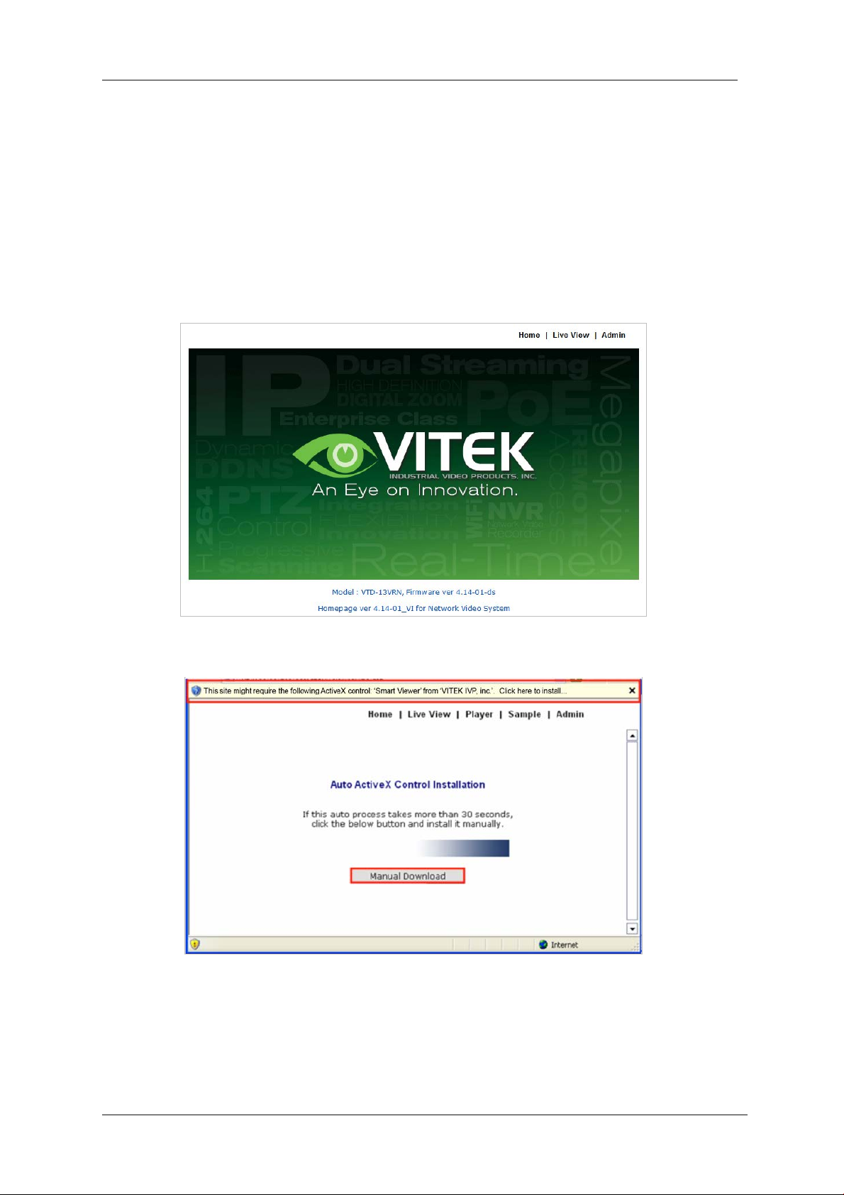
ENVI Series: VT-IPSN16M
17. Installing and Uninstalling
17.1. Installing ENVI Series Viewer
Connect to the Vitek Camera/Server using Internet Explorer, and click Live View on the main page.
Then ENVI Series Viewer will be automatically downloaded and installed. If an Internet connection
is not available, it's possible to manually install the program file in advance (from supplied CD) and
connect to the Vitek Camera / Server later.
17.1.1. Installing on Web Browser
Click 'Live View' after access to Vitek® Server on Internet Explorer.
If you're using Windows XP Service Pack 2 or later, the Information message will show up as
seen below. Click the Information message.
If the Information message doesn't come up due to the problems like network failure, you can
start the manual installation as shown in the next section.
80
Page 82
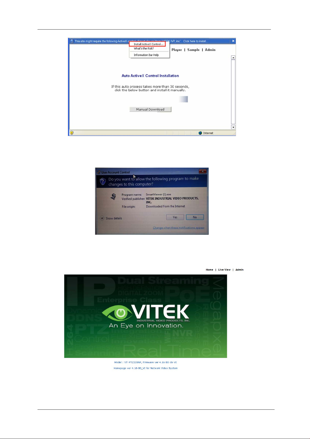
ENVI Series: VT-IPSN16M
Click the Install ActiveX Control, and the pop-up window will be displayed as above. Click the
Install button.
Click “YES” to allow program to run.
After the installation is successfully completed, ENVI Series Viewer window will be displayed.
81
Page 83
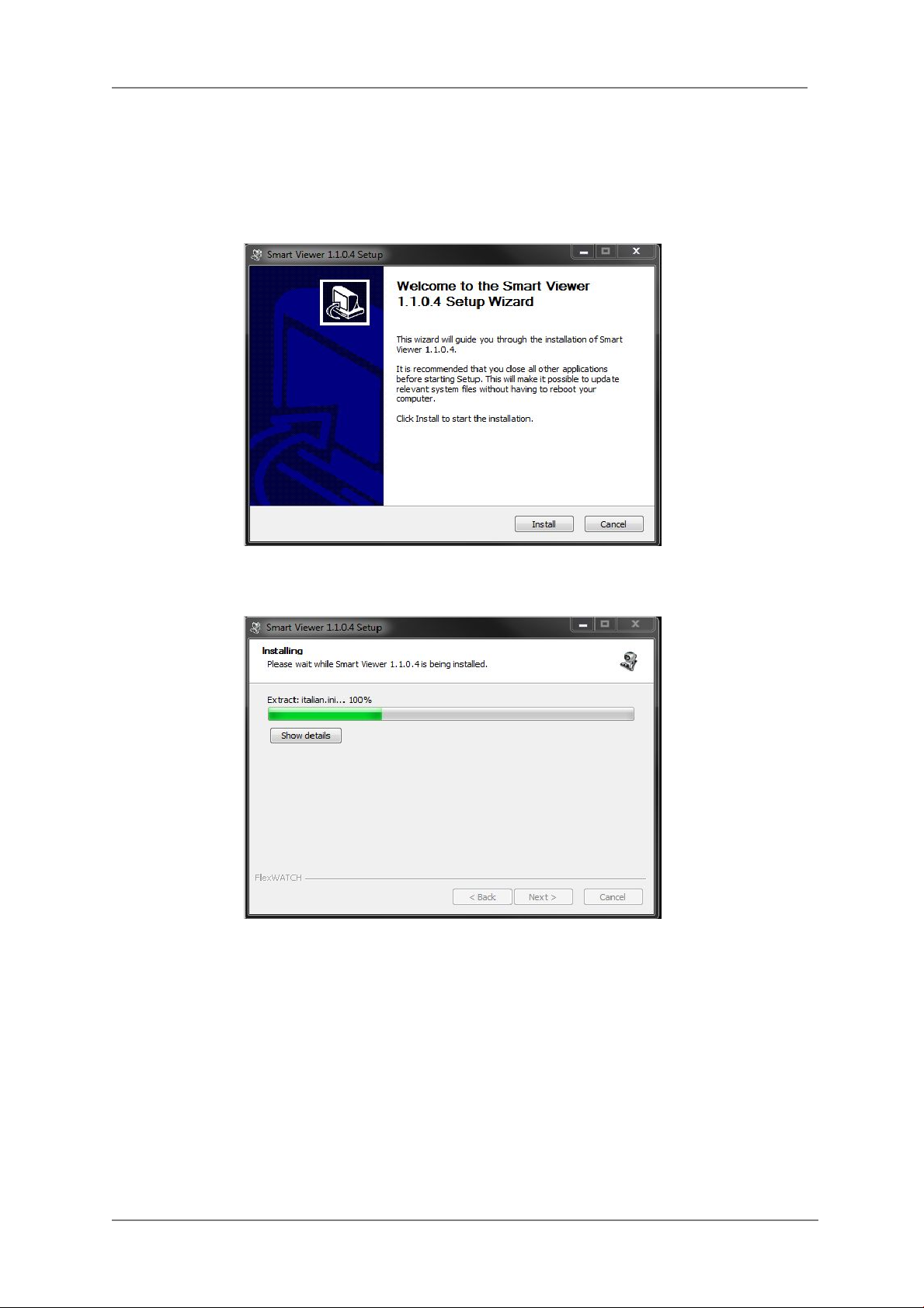
ENVI Series: VT-IPSN16M
17.1.2. Manual Installation
When an Internet connection is not available or having some difficulties, you can manually install
from the supplied CD using ENVI Series Viewer program file. Execute the downloaded file, and you
will see the ENVI Series Viewer Setup Wizard window as shown below. Click the Install button to
start installing.
The following window will be displayed during the insta llation.
After installation is successfully completed, the following window will be displayed. Click the Finish
button.
82
Page 84
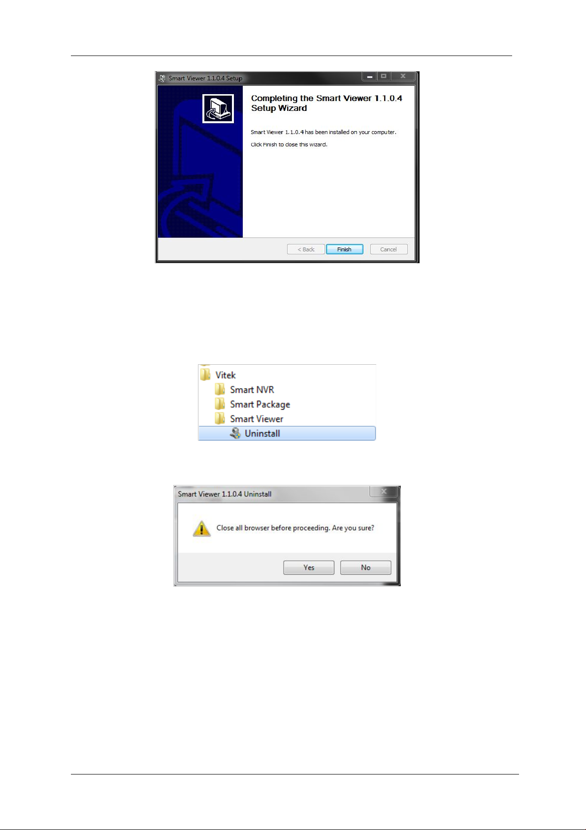
ENVI Series: VT-IPSN16M
17.2. Uninstalling ENVI Series Viewer
There are two ways to uninstall ENVI Series Viewer program from your computer. Before
uninstalling, close all the Internet Explorer windows.
17.2.1. Uninstalling with Program Menu
Click Uninstall and the following window will be shown. Click the Yes button.
If the uninstall is successful, the following window will be displayed. Click CLOSE to finish.
83
Page 85
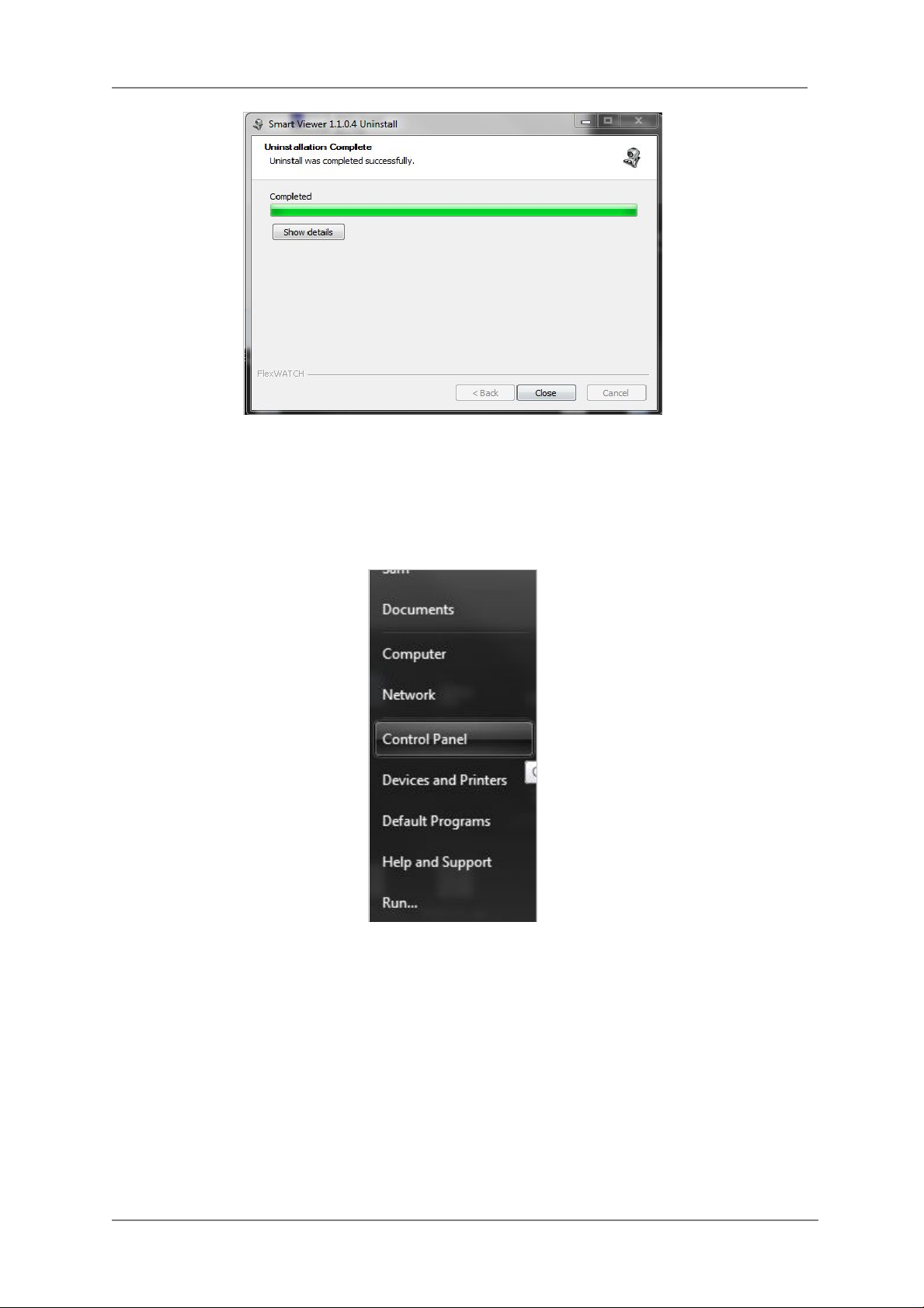
17.2.2. Uninstalling on Con trol Panel
ENVI Series: VT-IPSN16M
Click Start button on the screen, then select the Control Panel.
In the Control Panel window, double-click the Add or Remove Programs icon.
84
Page 86
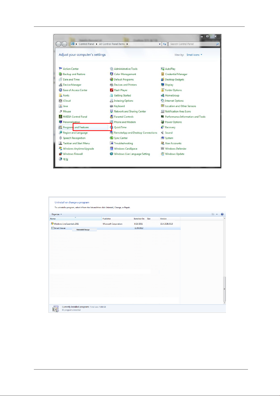
ENVI Series: VT-IPSN16M
You will see the Currently installed programs list. Click ENVI Series / (Smart Viewer)
button,
You will see the Uninstall or change a program list. Click ENVI Series / (Smart Viewer)
button, and then right click Uninstall /Change button. Then, i t will start uninstalling the program.
18. Starting ENVI Series Viewer
Once ENVI Series Viewer is installed in your computer, you can start it by connecting to the Vitek
85
Page 87
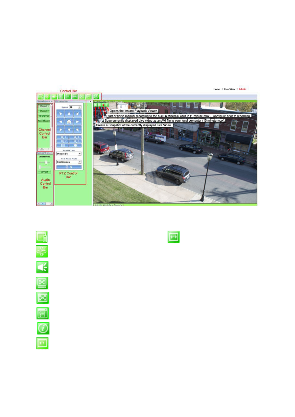
ENVI Series: VT-IPSN16M
Camera / Server using Internet Explorer and select Live View on the main menu.
The appearance of ENVI Series Viewer window varies depending on what type of Vitek Server is
connected (Network Video Server, Network Camera, or Network Video Recorder).
• ENVI Series Viewer window for Network Video Server or Network Camera
18.1. Control Bar
Displays and hides Channel control bar System Information Display
Displays and hides PTZ control bar
Displays and hides Audio control bar
Display image by aspect ratio
Displays image normal screen
Display Enhancer o n/off (uses more CPU)
Display Full / Normal screen
Displays image in original size
86
Page 88
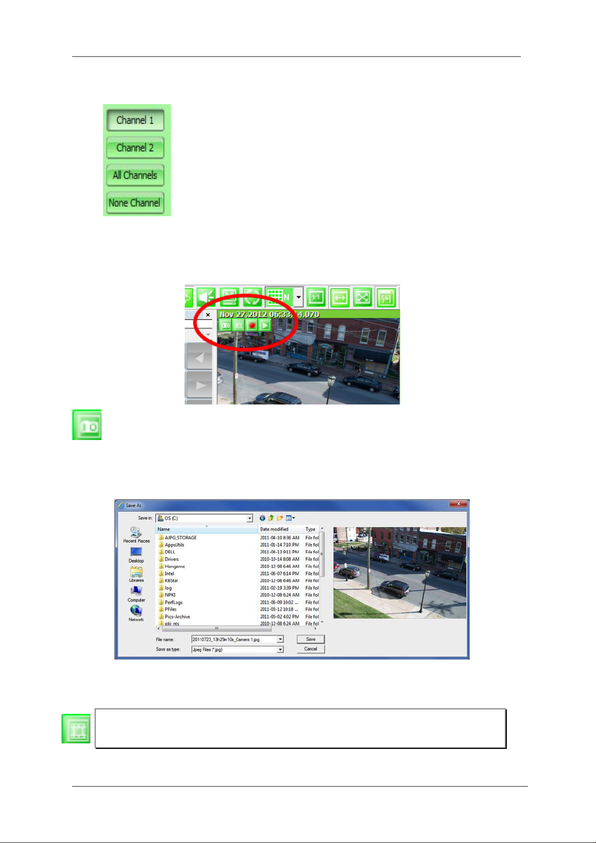
ENVI Series: VT-IPSN16M
18.2. Channel Control Bar
Displays or hides live view video from channel 1
Displays or hides live view video from channel 2
Displays or hides live view video from ALL channels
No Display
18.3. OSD Channels Buttons
18.3.1. Saving as Image File
In ENVI Series Viewer, Live video currently displayed can be captured and saved as an
image file either in JPEG or BMP format. Select the live view video you want saved, and click
Snapshot button o n OSD Channel Buttons. The following window will be displayed.
In this dialog box, you see the captured image to be saved. Enter the folder and file name, and
click the Save button, then the image will be saved with the name you entered.
Note: If live view video is in MJPEG format, the image will be saved as a JPE G file. If the
video is in MPEG-4 or H.264 format, it wi l l be saved in BMP format.
87
Page 89
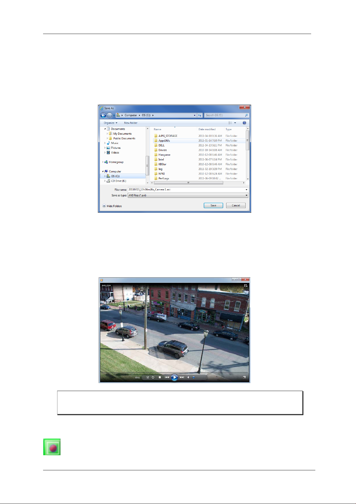
ENVI Series: VT-IPSN16M
18.3.2. Saving as Video File
In ENVI Series Viewer, Live video currently displayed can be captured and recorded as a video file
in AVI format. Select a live view you want to save, and click RecAvi button on OSD Channel
Buttons. Clicking it again will stop recording. Max duration is 10 minutes and recording will be
stopped after 10 min if left un-clicked.
In video files recorded from M-JPEG format video, the time information file will be generated in
SMI subtitle format, which puts time stamp every second. When you play back the recorded video,
the time stamp will be displayed as a subtitle on the video screen as shown in the picture belo w.
(upper left)
Note: When you play back videos recorded from MPEG-4 or H.264, proper CODEC’s m ay
be required.
18.3.3. Manual Recording
To manual record from network cameras with built-in local storage (microSD), live video
88
Page 90

ENVI Series: VT-IPSN16M
can be recorded to the microSD card by clicking this button. The recorded video can be viewed by
Instant Playback feature of OSD Channel B uttons or by runni ng ENVI Series Player program. To
finish, click the icon again.
Max duration is 1 minute
and recording will be stopped after 1 minute.
18.3.4. Instant Playback
For network cameras with local storage (microSD), Instant Playback is supported. Clicking
the Instant Playback button from the OSD menu will open the window below.
Instant playback will scan the video data up to 1 min before it was executed. And scanned data
will be played automatically
89
Page 91
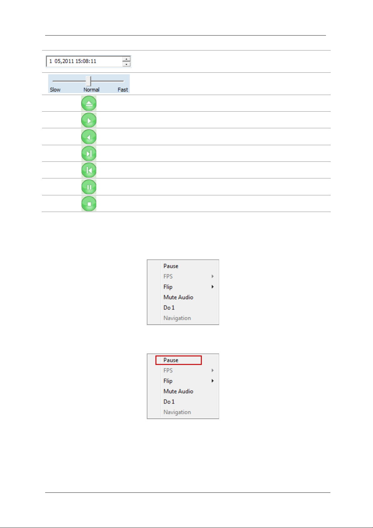
ENVI Series: VT-IPSN16M
Set the beginning of video data. Instant playback will scan 1 min
after this.
Se the playback speed.
Begin searching da ta
Playback
Reverse playback.
1 frame playback
1 frame reverse playback
18.4. Extended Features
When you click the right mouse button on the Live View Window, a pop-up menu will appear for
extended features as shown below.
18.4.1. Pausing Live Video
Click the Pause button to stop and resume live view video.
Pause
Stop
18.4.2. FPS Control
FPS (Frame per Se cond) can be controlled only in MJPEG mode. In MPEG4 and H.264 video mode ,
FPS control is not supported.
90
Page 92

ENVI Series: VT-IPSN16M
18.4.3. Flip Control
Flip Control: The horizontal view of the image can be changed using the (mirror) function. The
vertical view of the image can be change d using the (flip) function.
91
Page 93

ENVI Series: VT-IPSN16M
ENVI Viewer
A
19. EN-V-R: Introduction
This User's manual explains how to set up EN-V-R software in your PC. EN-V-R is the integrated system
software for video security applications, which runs on Microsoft’s Windows-based computers. Some of
major features of EN-V-R are listed below.
Provides main features of Live view, Playback, Record, Backup
Event, motion, scheduled recording & conditional playback
Motion-JPEG, MPEG-4, H.264 stream supported
Supports various vendors’ IP de vices (Multi Vendor Version only) for recording and retransmission of
video, voice, and data
Supports Megapixel cameras (up to 3M pixels)
Users can connect to EN-V-R via web browsers to access live video, Audio, and data, and search for
video to play back
Up to 128 channels supported for cameras
Note: A product-key is required for proper installation of EN-V-R program. You can still
install EN-V-R in 10-working day trial mode if a product-key is not entered during
installation. (Multivendor software only)
(HTTP port)
Analog
EN-V-R
ENVI Player
ENVI Map
ENVI Alarm
92
Page 94

ENVI Series: VT-IPSN16M
Support
9
N/A 9 36
Yes
160 TB
64
N/A
64
256
Yes
160 TB
128
N/A
128
512
Yes
160 TB
D1
Intel Core2Duo T5200
1.0GB
D1
Intel Core2Duo E6700
1.0GB
1080P
Intel Xeon X5680 D ual CPU
4.0GB
720P
Intel Xeon X5670 D ual CPU
6.0GB
1080P
Intel Xeon E7-4850 Dual CPU
6.0GB
720P
Intel Core i-5 460M
1.5GB
720P
Intel Core i-5 -2400S
2.0GB
720P
Intel Xeon X5550 D ual CPU
4.0GB
D1
Intel Xeon X5687 D ual CPU
4.0GB
20. Requirements for Installation
20.1. EN-V-R Versions
EN-V-R is supplied to customers in different versions for each appropriate application. Users will need t o
choose the right versions for their needs.
Version
Types
Evaluation 128 10 days 128 256 Yes 160 TB
Free 16 N/A 16 64 No 160 TB
Multivendor
20.2. System Requirement for PC
For best quality and performance, your computer needs to meet the minimum requirement as below.
Microsoft Windows XP Pro, Windows 7 Pro or higher, Video Card(256MB Ram, 1024x768 or higher)
Compression # of Channels Resolution Recommended CPU Memory
Register
Channels
16 N/A 16 64 Yes 160 TB
32 N/A 32 128 Yes 160 TB
16 Channels
Time
Restriction
Recording
Channels
720P Intel Core2Duo E7550 1.5GB
1080P Intel Core i-5-2500S 2.0GB
Retransmission
Streams
Other
vendors
Max Recoding
Capacity
H.264
Motion-JPEG
32 channels
64 channels
128 channels
16 Channels
32 channels
64 channels
128 channels
720P Intel Core i-5 75 0 2.0GB
1080P Intel Core i-7 97 0 4.0GB
D1 Intel Core i-5 661 1.5GB
720P Intel Xeon X5660 4.0GB
D1 Intel Xeon X5507 Dual CPU 4.0GB
D1 Intel Core2Duo E6700 1.0GB
1080P Intel Core i-5 -2500 3.0GB
D1 Intel Core i-5 661 1.5GB
1080P Intel Xeon X5590 Dual CPU 4.0GB
D1 Intel Core i-5 -2500 3.0GB
1080P Intel Xeon E7-4850 Dua l CPU 6.0GB
720P Intel Xeon X5690 Dual CPU 6.0GB
1080P Intel Xeon E7-4850 Dual CPU 6.0GB
93
Page 95

ENVI Series: VT-IPSN16M
Note: Above PC requirements are based on running EN-V-R program only. If other software needs to run
along with EN-V-R at the same time, you may need additional performance level for your PC. It is
recommended to check actual performance and disk capacity before selecting a PC for EN-V-R.
21. Installing EN-V-R
After downloading EN-V-R, double click EN-V-R Setup icon to start installation. The following
window will be displayed on the screen. Before installing, check the version of the EN-V-R which
is shown on the window.
You may encounter the following security warning. To continue installing the program, click Yes button.
Then select language for installation.
You will see the below window, then click Next button.
The default location for installation is C:\Program Files\Vitek. It is recommended to install in this folder,
94
Page 96
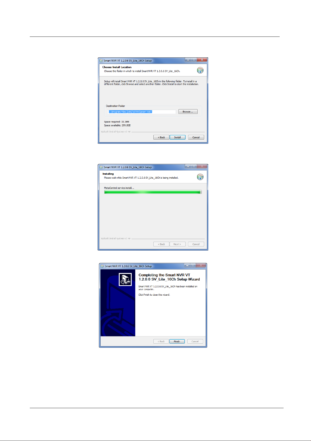
ENVI Series: VT-IPSN16M
but if you want to change it to another location, click Browse button to choose a proper path.
Now click Install button.
You will see the progress of copying install files to the hard drive as shown below, once is comple ted click
on NEXT.
Click Finish to complete the Installation.
After installing EN-V-R program for the first time, it needs to be configured before use, so it automatically
executes the configuration program, which is called EN-V-R Configurator.
95
Page 97
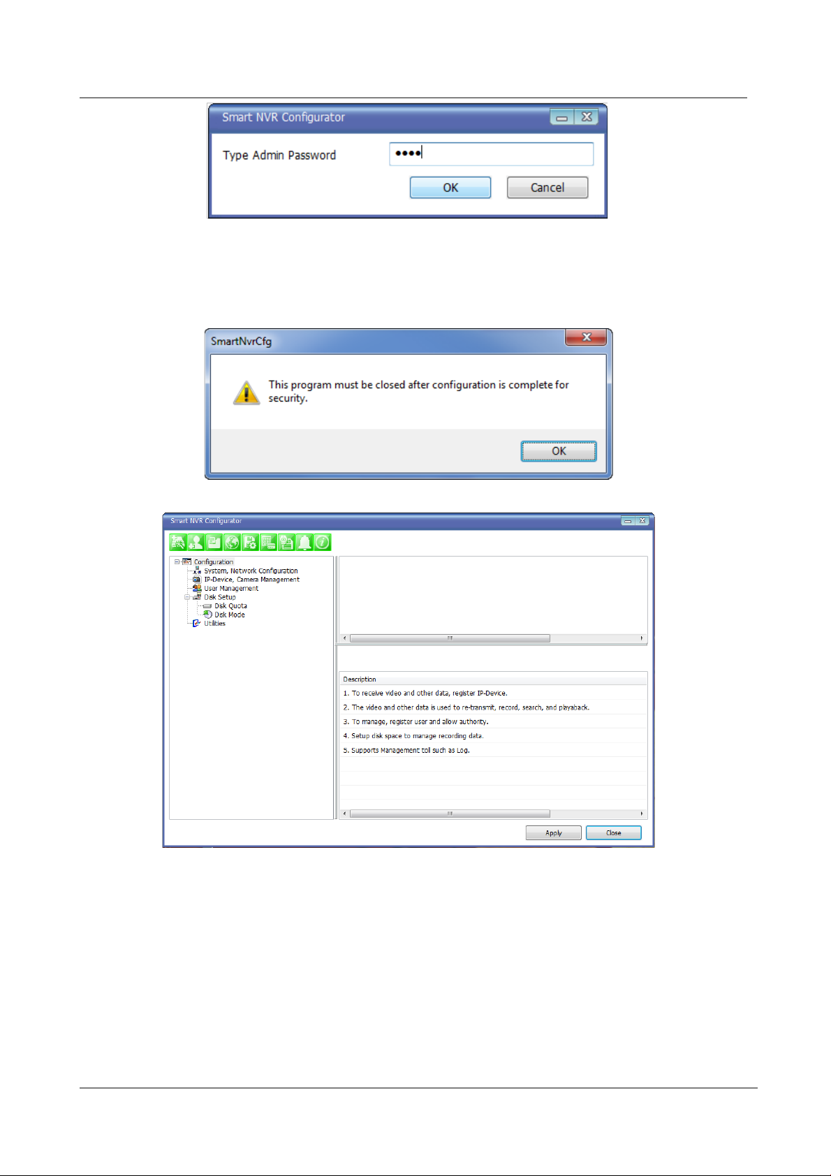
Enter the proper Admin Password. The default password is root.
The following screen will be displayed, click OK to continue.
Now you will see EN-V-R Configurator window on the screen.
ENVI Series: VT-IPSN16M
To use EN-V-R Configurator program, refer to Section 27. Starting EN-V-R Configurator on page 99.
22. Uninstalling EN-V-R
22.1. Closing Active EN-V-R
If you need to uninst all EN-V-R, first you need to make sure EN-V-R program is not running on your
computer by checking the system icon. As you see on the following picture, you can easily find out if ENV-R service running.
96
Page 98
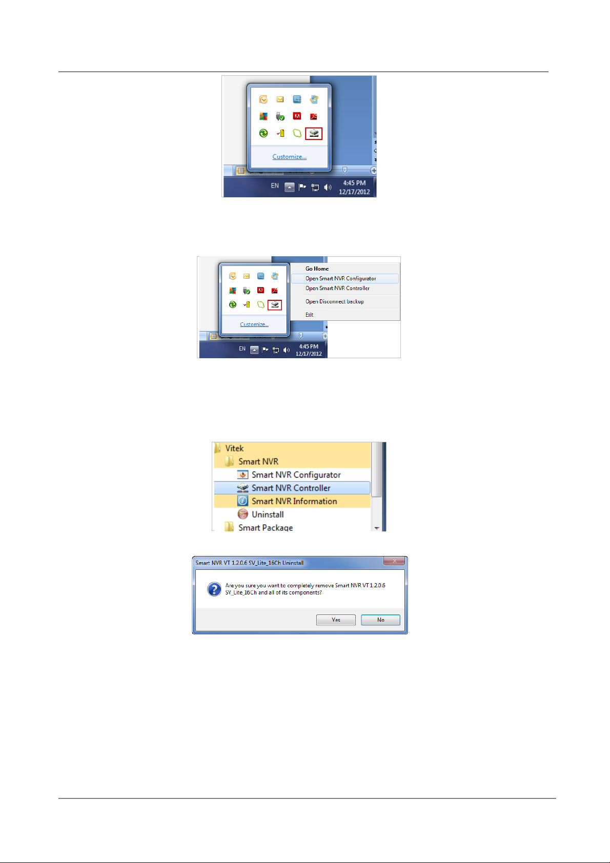
ENVI Series: VT-IPSN16M
If EN-V-R is not running, you can go ahead to the next section of uninstalling the program. If EN-V-R is
active, place the mouse pointer on the EN-V-R icon, and click the right mouse button. You’ll see the popup menu. Select Exit.
Then the EN-V-R icon disappears, and you know that EN-V-R is no longer running on your computer. Now
you’re ready to start uninstalling.
22.2. Executing Uninstaller
To start uninstalling, click Start >All Programs >Vitek>EN-V-R>Uninstall.
When the following window appears, click YES button.
The progress of uninstalling is displayed.
97
Page 99
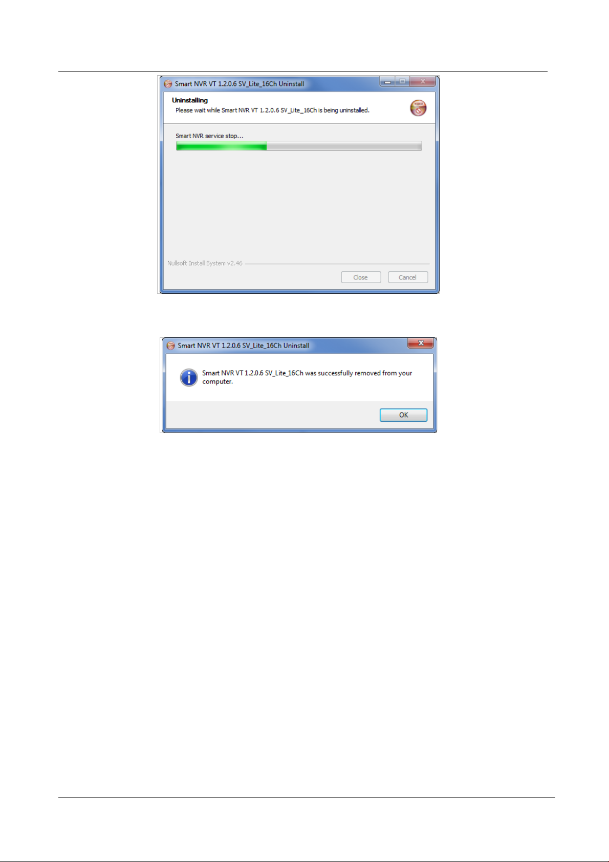
ENVI Series: VT-IPSN16M
After all the install files are deleted, the following window will be displayed. Click OK button on the
following window to complet e the uninstalling.
23. Components of EN-V-R Program
EN-V-R consists of three programs, (
23.1. EN-V-R Configurator
EN-V-R Configurator is used to set up various parameters and conditions of EN-V-R Service. Users ca n
register, modify, and delete IP devices and users with this program. It also provides configuring tools for
recording, alarm, event, and other functions.
23.2. EN-V-R Service
EN-V-R program is a Windows service and runs in a background mode, which means that it is not shown
on the Windows desktop. EN-V-R receives video, audio, alarm, even data from IP devices over the
network, and then it can record the data on the hard dri ve or retransmit to users. Starting, terminating
and restarting of EN-V-R program can be done by using EN-V-R Configuration or EN-V-R Controller.
EN-V-R Service, EN-V-R Config urator, and EN-V-R Controller
).
23.3. EN-V-R Controller
EN-V-R Controller program is used to start or stop the EN-V-R service.
98
Page 100
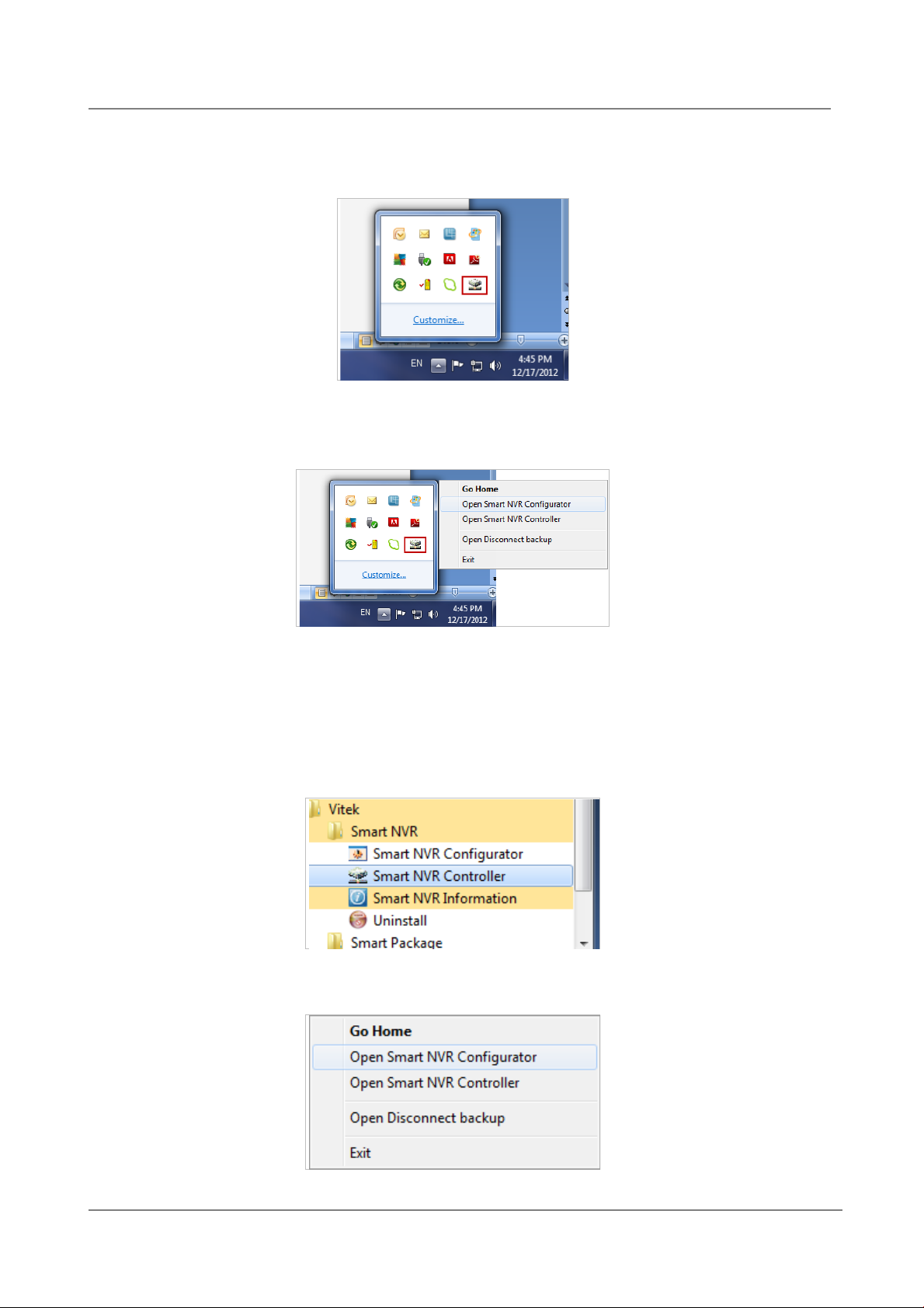
ENVI Series: VT-IPSN16M
23.4. EN-V-R System Tray Menu
After you finish installing EN-V-R, you will find the EN-V-R icon on the system tray, which is located right,
bottom part of the Windows desktop.
Move the cursor over the icon, and right click. The following pop-up menu will show. You can open EN-VR Configurator or EN-V-R Controller program from this menu, or you can go to the Home page of the ENV-R program for live view or playback.
24. Starting EN-V-R Configurator
EN-V-R Configurator starts automatically right after installation is completed; you may also click the EN-VR icon on the Windows desktop.
If EN-V-R program is already running in background, you may also select the EN-V-R icon on the system
tray by clicking right button of the mouse.
99
 Loading...