

Vitek VTD-HOCR6E2812-V User Manual
VITEK
VITEK
FEATURES:
• 1/2.9” Sony® Progressive Scan CMOS (IMX222)
• 2.1 MegaPixel with Full 1080p/720p HD-SDI (SMPTE292M) /
EX-SDI Output
• Six (6) High Power 850nm IR LEDs with up to 160’ foot range
• MegaPixel IR Corrected 2.8-12mm Varifocal Lens Included
• Mechanical IR Cut Filter (True Day/Night)
• 16:9 Video Format
• Advanced OSD Functions: Motion Detection, Sharpness, Gamma,
Mirror, Flip, DSS, Freeze, D-Zoom, ACE, WDR, 3D-DNR, Defog,
Privacy, HLM
• 100% Pure Digital Transmission of video data
• Up to 1000’ HD Transmission Range (Depending on cable
characteristics and integrity)
• IP68 Weather Resistance
• 12VDC/24VAC Dual Voltage Operation
• Available in Ivory or Black
VTD-HOCR6E2812-V
2.1MP HD-SDI / EX-SDI IP68 Vandal
Resistant WDR IR Varifocal Dome Camera
2 3
Safety Precaution
CAUTION: TO REDUCE THE RISK OF ELECTICAL
SHOCK, DO NOT REMOVE COVER (OR BACK).
NO USER SERVICEABLE PARTS INSIDE.
REFER SERVICING TO QUALIFIED SERVICE PERSONNEL
To prevent electrical shock and risk of fire hazards, do not expose this unit
to rain or moisture and only use specified power source..
Warning :
This equipment has been tested and found to comply with the limits for a Class
A digital device, pursuant to part 15 of the FCC Rules. These limits are designed
to provide reasonable protection against harmful interference when the equipment
is operated in a commercial environment. This equipment generates, uses, and
can radiate radio frequency energy and, if not installed and used in accordance with
the instruction manual, may cause harmful interference to radio communications.
Operation of this equipment in a residential area is likely to cause harmful
interference in which case the user will be required to correct the interference at
their own expense.
Caution :
Any changes or modifications in construction of this device which are not expressly
approved by the party responsible for compliance could void the user's authority
to operate the equipment.
Main power quality should be that of a typical commercial environment. If the user
of the model requires continued operation during power interruptions, it is
recommended that the device be powered from an uninterruptible power supply
(UPS).
The symbol is intended to alert the user to the presence of important
operating and maintenance (servicing) instructions in the literature
accompanying the unit.
The symbol is intended to alert the user to the presence of uninsulated
"dangerous voltage" within the product's enclosure that may be of
sufficient magnitude to constitute a risk of electrical shock.

3
Safety Precaution
NOTICE
• The image used in this instruction manual are processed to help
comprehension and may differ from actual video of the camera.
• Avoid installing in areas where shock or vibration may occur.
• Pay attention to safety when running the connection cables and
make sure that the cables are not subject to heavy loads, kinks,
moisture or damage.
• Never open the device (no user serviceable parts inside). The
warranty becomes void if repairs are undertaken by
unauthorized persons.
• Maintenance and repair have to be carried out only by authorized
service centers.
• Use only a mild detergent to clean the housing.
• The camera should never be operated beyond the technical
specifications. This can lead to damaging the device and void
the warranty.
• The camera should never be operated in water.

4 5
Contents
p. 2~3
Safety Precaution
p. 4
Contents
p. 5
Dimensions
p. 6
Installation Instructions
p. 7
Zoom & Focus
Pan & Tilt
p. 8
Attaching the Dome
p. 9
Using the OSD Controller
p. 10
Menu Set Up
p. 10-24
Operating Instructions
p. 25
Specifications
p. 26
On Cue VT-HDOCE Series
p. 27
Limited Product Warranty
5
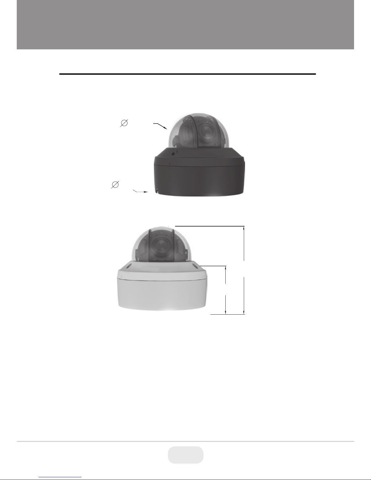
Dimensions
(unit : inches)
4.75”
2.89”
3.94”
5.79”
6 7
Installation Instructions
The Installation method is the same for the Varifocal and Fixed lens camera.
The product dimensions are the same for either camera.
1. Place the mounting template at the installation position and drill the ceiling or
wall if needed.
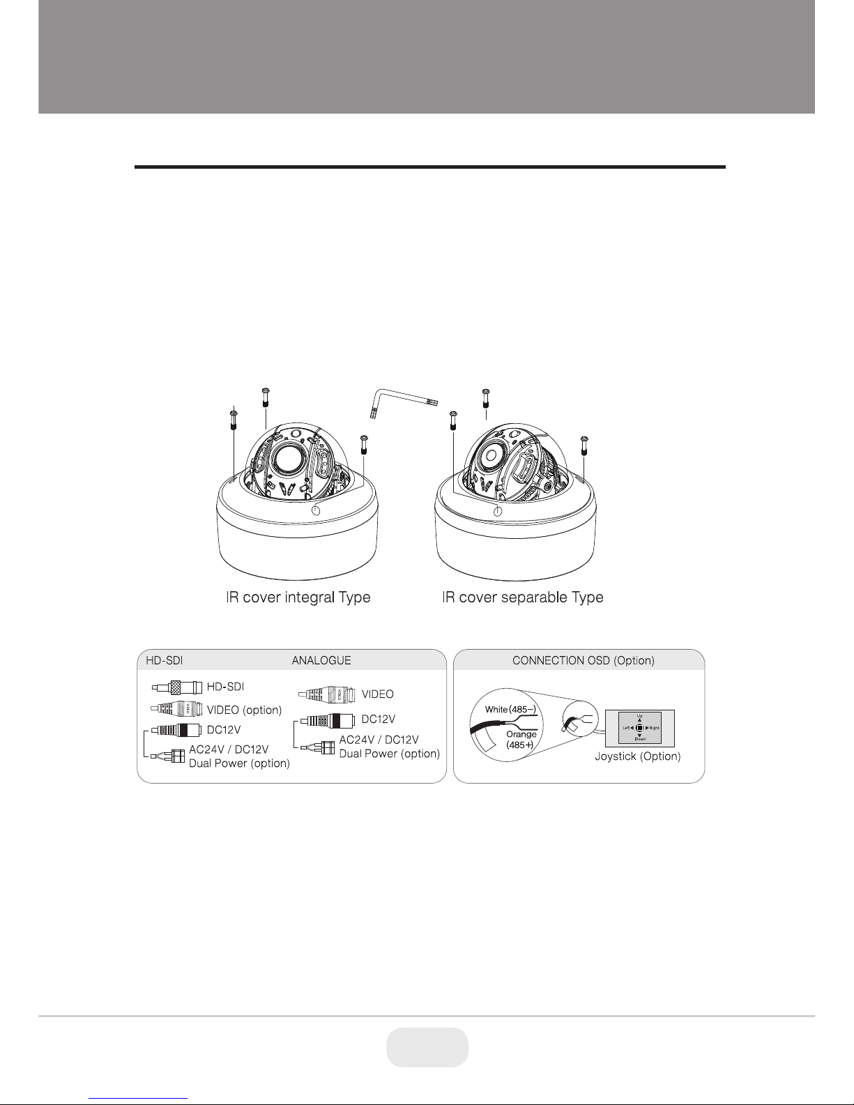
2. Open the dome cover by loosening screws. Use the torque wrench supplied.
7
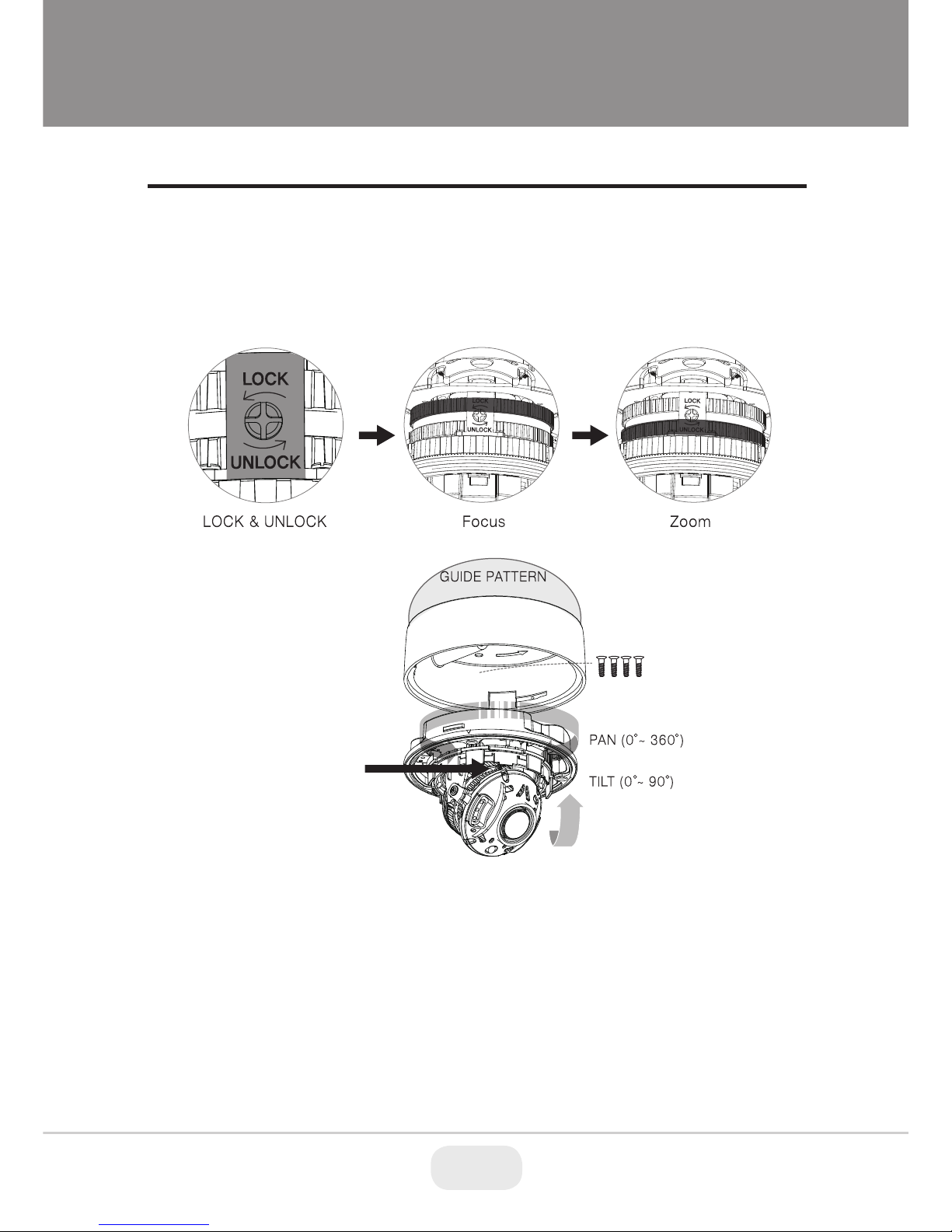
Installation Instructions
Zoom & Focus (Varifocal)
1. While the camera is open using a phillips screw driver loosen the screw to
adjust the Zoom & Focus as shown in the images below.
2. Tighten the screw to hold desired Zoom & Focus position.
Lock & Unlock
Limit of Pan & Tilt
1) Pan limit:
Pan is limited to +/- 360°. Do NOT force the gimbal over the limit, this will
prevent internal damage.
2) Tilt limit:
Tilt is limited to 0° min ~ 90° max. with reference to the ceiling when the
inclination of camera module is 0°, that is, the image is aligned horizontally.
8 9
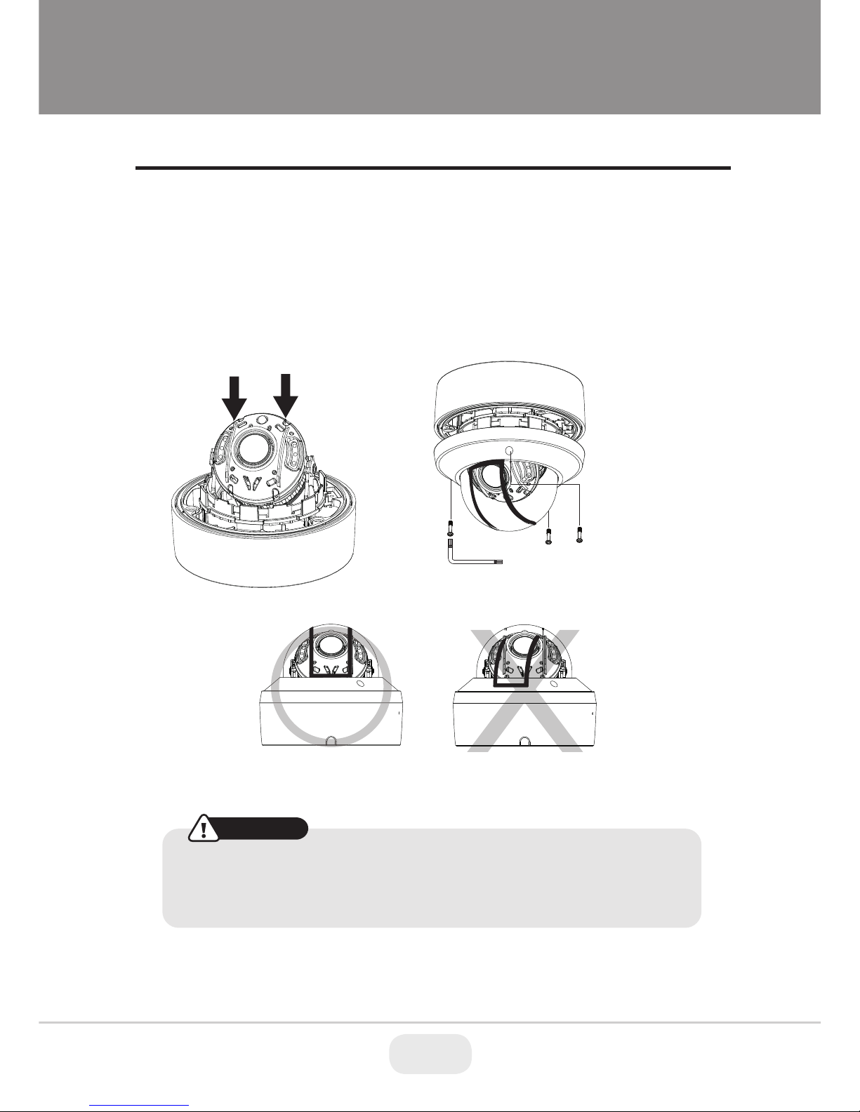
Installaton Instructions
Attaching the Dome
There are 2 locations of the Hemisphere Guide in the IR dome cover.
1. To attach the dome cover line up the Hemisphere Guides as shown below.
2. Attach the dome cover to the dome base unit and tighten the assembly
screws using the torque wrench.
CAUTION
• If the Hemisphere Guides are not correctly assembled you may see
a diffused reflection.
• Please line up the Hemisphere Guides as instructed for correct view.
Correct Assembly Incorrect Assembly
Hemisphere Guides
Torque Wrench
9
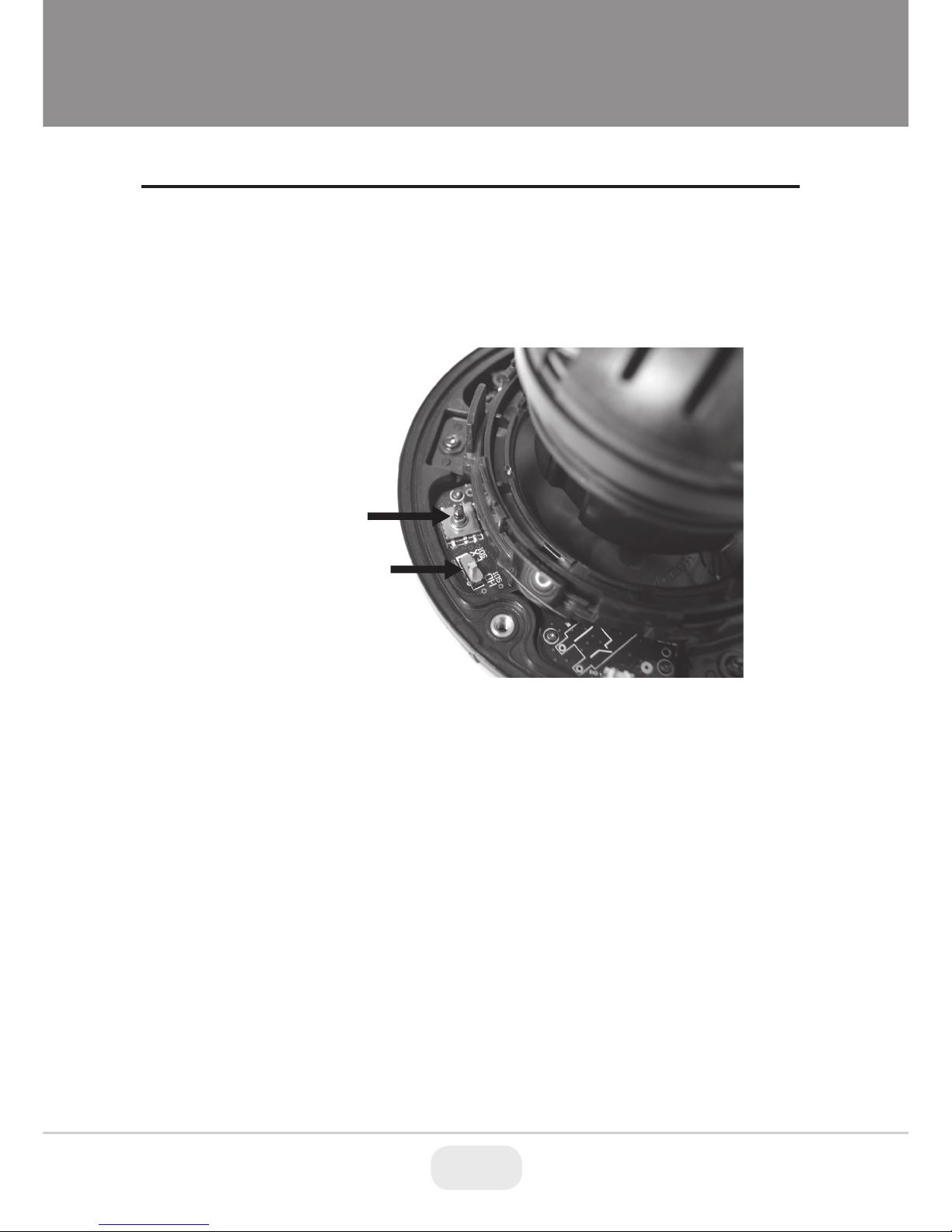
Using OSD controller
• Setup menu can be accessed and controlled by OSD control joy stick on the
inside of camera unit.
• EX-SDI / HD-SDI switch is located on the inside of camera unit.
Operating Instructions
EX-SDi / HD-SDI Switch
OSD control
 Loading...