

Page 1
VITEK
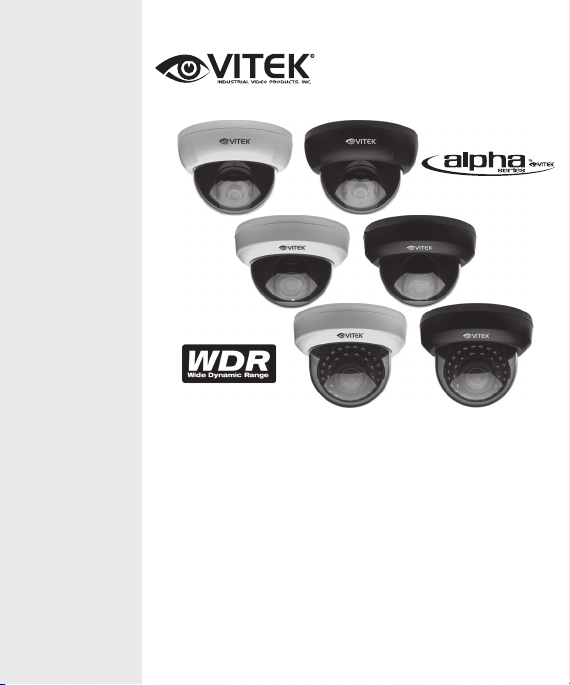
• 650 TV Lines of Resolution
• 1/3” Sony SuperHAD II CCD
• Hercules II DSP Engine
• 3.6mm Fixed and 2.8~12mm IR Corrected
DC Auto-Iris Lens Options
• Available with 35 IR LEDs (120’ Range)
• Advanced OSD Functions: WDR, 3D DNR,
DSS, DIS, Sens-up, Motion Detection, Privacy
• Secondary Video Output (Cable Included)
• 3-Axis Mount for Optimum Viewing Angle
Alpha Series Indoor
WDR Dome Cameras
Page 2

TABLE OF CONTENTS
BOX CONTENTS / MOUNTING ACCESSORIES 2
AVAILABLE MODELS 3
VTD-A4F/I INSTALLATION 4
VTD-A2812/I INSTALLATION 5
VTD-AR2812/I INSTALLATION 6
INSTALLATION TIPS 7
OSD OPERATION 8-27
DIMENSIONS 28
SPECIFICATIONS 29-31
1
Page 3

BOX CONTENTS AVAILABLE MODELS / ACCESSORIES
1) Dome Camera
2) Mounting Accessories
3) This instruction Manual & Mounting Template
BOX CONTENTS
Self Tapping Screws
For attaching the housing base to a solid surface.
Type #: Phillips ST4x30
Qty: 4
BOX CONTENTS AVAILABLE MODELS / ACCESSORIES
1) Dome Camera
2) Mounting Accessories
3) This instruction Manual & Mounting Template
BOX CONTENTS
Self Tapping Screws
For attaching the housing base to a solid surface.
Type #: Phillips ST4x30
Qty: 4
Secondary Video Output Cable
To be used with a service monitor for adjusting
the angle, focus and zoom.
Qty: 1
BOX CONTENTS
1) Alpha Dome Camera
2) Mounting Accessories
3) Secondary Video Output Cable
4) This instruction Manual & Mounting Template
MOUNTING ACCESSORIES
Self Tapping Screws
For attaching the housing base to a
solid surface.
Type #: Phillips ST4x30
Qty: 4 (2 screws - VTD-A4F/I)
Secondary Video Output Cable
To be used with a service monitor for
adjusting
the angle, focus and zoom.
Qty: 1
2
Page 4

AVAILABLE MODELS
VTD-A4F/IW
Indoor High Resolution WDR Dome Camera with White Base.
VTD-A4F/IB
Indoor High Resolution WDR Dome Camera with Black Base.
VTD-A2812/IW
Indoor High Resolution WDR Varifocal Dome Camera with White
Base.
VTD-A2812/IB
Indoor High Resolution WDR Varifocal Dome Camera with Black
Base.
VTD-AR2812/IW
Indoor High Resolution Infrared WDR Varifocal Dome Camera
with White Base.
VTD-AR2812/IB
Indoor High Resolution Infrared WDR Varifocal Dome Camera
with Black Base.
3
Page 5
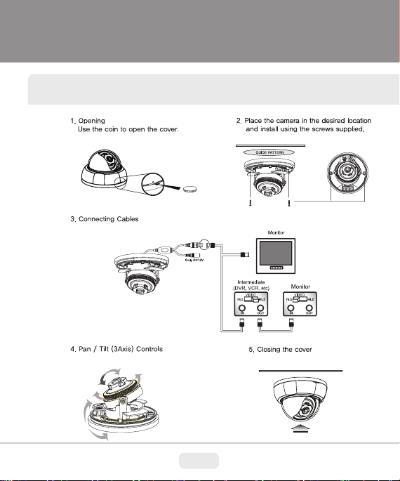
VTD-A4F/I INSTALLATION
* See Installation Tips on page 8
4
Page 6
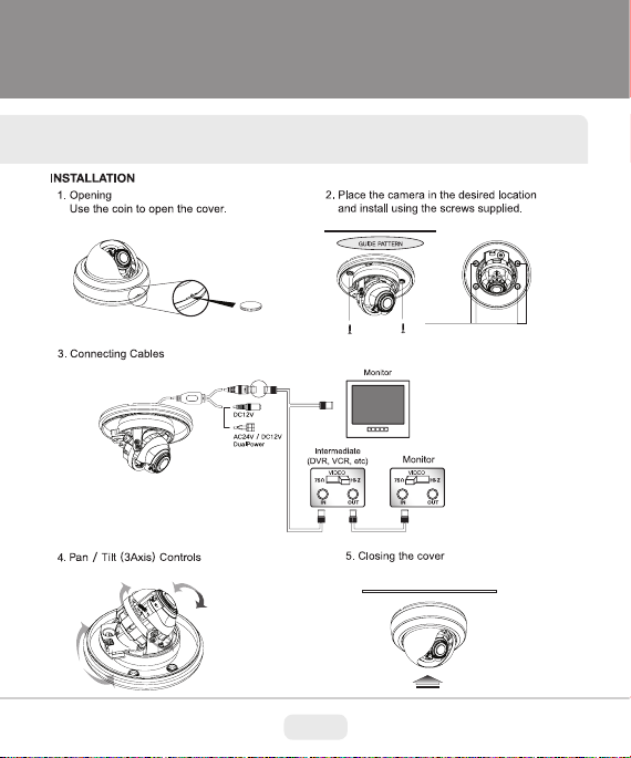
VTD-A2812/I INSTALLATION
* See Installation Tips on page 8
5
Page 7
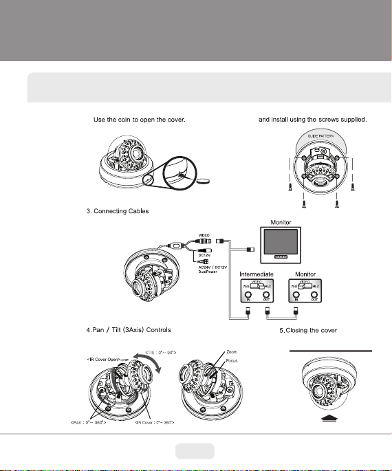
VTD-AR2812/I INSTALLATION
* See Installation Tips on page 8
6
Page 8

INSTALLATION TIPS
1.) Power Consumption - Amperage/Voltage
It is of utmost importance that the proper Voltage and Amperage is used when
applying power to your VITEK Alpha Series Dome Camera. They can be powered by either 12V DC or 24V AC (except for the model VTD-A4F/I - 12V DC
only). Always use a UL Listed power transformer.
The Amperage must be measured at the camera location. It is very important
that the camera receives no less than the required Amperage or it will be
“Starved” and eventually die out. Cameras with Infrared LEDs require substan-
tially more Amperage than others so please refer to the Specications (page
24-26) for the camera you are installing.
2.) Extending the Power:
The cable may be extended up to 100 feet by using 18 Gauge (or thicker)
stranded wire - possibly longer depending on the amperage of the transformer
(see appropriate electrical guides to determine resistance). Simply cut the
power connector off of the transformer and splice the wire using a wire nut or
solder and Electrical tape for isolation. DO NOT ALLOW THE BARE WIRES
TO TOUCH ONE ANOTHER.
3.) Extending the Video Cable
Always use 75 ohm copper braid coax (RG59U or thicker) for video signal
transmission up to 500 feet - possibly longer depending on the grade of cable
and percentage of braid. VITEK Alpha Series Dome Cameras utilize BNC
Video connectors which come in male or female in order to extend the coax to
the desired distance (see appropriate installation guide to learn how to properly
install a BNC Connector).
7
Page 9

SETUP MENU
OSD OPERATION
EXPOSURE
WHITE BALANCE
DAY&NIGHT
IMAGE ADJUST
MOTION
PRIVACY
SPECIAL
EXIT
LENS AGC SENSE-UP BACKLIGHT 3D-DNR RETURN
AWB MODE R-Y GAIN B-Y GAIN RETURN
D&N MODE BURST C_SUP A_SUP DYNAMIC IR RETURN
MIRROR SHARPNESS GAMMA LSC MONITOR RETURN
MOTION AREA SENSITIVITY DISPLAY HOLD TIME
ALARM OUTPUT RETURN
MASK1 MASK2 MASK3 MASK4 MASK5 MASK6
MASK7 MASK8 RETURN
LANGUAGE TITLE COMMUNICATION DPC
FACTORY SET RETURN
8
Page 10
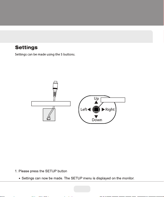
OSD OPERATION
Secondary Video Output
Push to Setup
9
Page 11
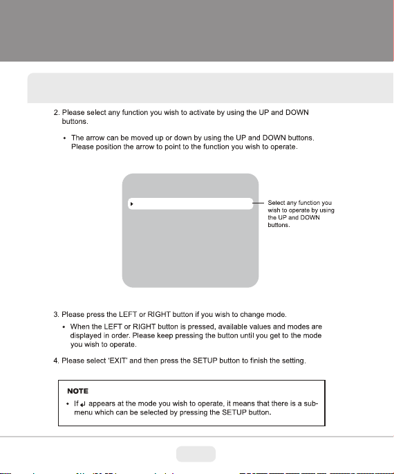
MAIN MENU
EXPOSURE
WHITE BALANCE
DAY&NIGHT
IMAGE ADJUST
MOTION
PRIVACY
SPECIAL
EXIT
OSD OPERATION
10
Page 12

OSD OPERATION
EXPOSURE
The EXPOSURE menus SHUTTER/IRIS controls, BLC, HLI, D-WDR, AGC and 3D DNR, will set SENSE-UP etc.
and it will be able to change a condition.
MAIN MENU
EXPOSURE
WHITE BALANCE
DAY&NIGHT
IMAGE ADJUST
MOTION
PRIVACY
SPECIAL
EXIT
LENS
AGC
SENSE-UP
BACKLIGHT
3D-DNR
RETURN
EXPOSURE
DC
HIGH
AUTO
OFF
AUTO
DC
BRIGHTNESS
E.SHUTTER
RETURN
025
1/60
LENS
EXPOSURE – LENS – DC
DC modes use DC-IRIS lenses and they control AE. Then, electronic shutter speed default 1/60.
EXPOSURE – LENS – DC - BRIGTNESS
BRIGHT : Setting for target brightness.
Controls DC IRIS at the bright value which is set. Bright control from 1 to 100.
EXPOSURE – LENS – DC – E.SHUTTER
LENS – DC mode setting.
E.SHUTTER : Electronic shutter value setting mode in DC IRIS
1/60(1/50), 1/100, 1/120FLK, 1/250, 1/500,1/1000, 1/2000, 1/4000, 1/10000, 1/100000 sec. (default : 1/50 (1/60))
RETURN
11
Page 13

OSD OPERATION
EXPOSURE
LENS
AGC
SENSE-UP
BACKLIGHT
3D-DNR
RETURN
EXPOSURE – LENS
Selection of LENS modes.
The ELC means xed LENS mode.
The ELC modes with electronic shutter AE controls.
When use DC-IRIS lens, DC-IRIS full open conditions.
DC modes use DC-IRIS lenses and they control AE. This time, Electronic shutter default shutter speed 1/60
EXPOSURE – LENS – MANUAL - BRIGHTNESS
BRIGHT : For target brightness control
AE controls this in compliance with a set bright control. Bright control from 1 to 100.
EXPOSURE – LENS – MANUAL - E.SHTTER
E.SHUTTER – setting value of electronic shutter
Select mode : Auto,1/60(1/50), 1/100, 1/120FLK, 1/250, 1/500,1/1000, 1/2000, 1/4000, 1/10000,
1/100000 sec. (default : AUTO)
When selecting in Auto mode (default) : The shutter mode from 1/60 to 1/100000 is controlled with automatic.
RETURN
MANUAL
HIGH
AUTO
OFF
AUTO
MANUAL
BRIGHTNESS
E.SHUTTER
RETURN
025
AUTO
AGC (Auto Gain Control)
EXPOSURE
LENS
AGC
SENSE-UP
BACKLIGHT
3D-DNR
RETURN
DC
HIGH
AUTO
OFF
AUTO
AGC : Auto Gain Control level set OFF / LOW / MIDDLE / HIGH.
12
Page 14

OSD OPERATION
SENSE-UP/NIGHT WATCH DSS
LENS
AGC
SENSE-UP
BACKLIGHT
3D-DNR
RETURN
EXPOSURE
DC
HIGH
AUTO
OFF
AUTO
EXPOSURE – SENSE - UP
When it is low dark condition, SENSE
AUTO / OFF / X2 / X4 / X8 / X16 / X32 / X64 / X128 / X256 / X512 / X1024
AUTO mode basically sets X4 by manufacture.
In case of SENSE-UP operating, the 3D-DNR is operated LOW level.
-
UP uses
BACKLIGHT
EXPOSURE
LENS
AGC
SENSE-UP
BACKLIGHT
3D-DNR
RETURN
DC
HIGH
AUTO
OFF
AUTO
13
Page 15

BACKLIGHT - BLC (Back Light Conpensation)
OSD OPERATION
EXPOSURE
LENS
AGC
SENSE-UP
BACKLIGHT
3D-DNR
RETURN
EXPOSURE - BACKLIGHT – BLC – BLC MODE
Select AUTO or MANUAL
Sets the total AE level at AE value of select window area.
AUTO, the case which modes will select seeks the darkest are a with automatic and photometry weight,
AE controls does.
EXPOSURE - BACKLIGHT – BLC – BLC MODE - MANUAL
BLC window setting at manual mode
TOP / BOTTOM / LEFT / RIGHT zone setting.
TOP : 0 ~ (BOTTOM – 1), 1 step.
BOTTOM : (TOP + 1) ~ 16, 1 step.
LEFT : 0 ~ (RIGHT - 1), 1 step.
RIGHT : (LEFT + 1) ~ 16, 1 step.
EXPOSURE - BACKLIGHT – BLC – BLC LEVEL
BLC level select mode.
Select OFF / LOW / MID / HIGH
DC
HIGH
AUTO
BLC
AUTO
BLC
BLC MODE
BLC LEVEL
RETURN
MANUAL
MID
BLC - MANUAL
TOP
BOTTOM
LEFT
RIGHT
RETURN
005
010
005
010
RETURN
14
Page 16

OSD OPERATION
BACKLIGHT - HLC (High Light Conpensation)
EXPOSURE
LENS
AGC
SENSE-UP
BACKLIGHT
3D-DNR
RETURN
EXPOSURE - BACKLIGHT - HLC
It is a function which reverses the area about strong light.
The HLI BLC mode control by BLC window area. (HBLC)
EXPOSURE - BACKLIGHT - HLC - HBLC
Sets HBLC area of separate way from HLC mode
HBLC LEVEL : OFF / LOW / MID / HIGH
HBLC zone sets regulate HBLC zone with square window of the screen.
TOP / BOTTOM / LEFT / RIGHT control mode
TOP : 0 ~ (BOTTOM – 1), 1 step / BOTTOM : (TOP + 1) ~ 16, 1 step / LEFT : 0 ~(RIGH T – 1), 1 step /
RIGHT : (LEFT + 1) ~ 16, 1 step
EXPOSURE - BACKLIGHT - HLC - MODE
Use mode set of HLC (ALL DAY / NIGHT).
ALL DAY : Always operating HLC
NIGHT : Only NIGHT environment operating. But if DAY conditi on, not operating HLC
EXPOSURE - BACKLIGHT - HLC LEVEL
Setting of HLC level ( 1 ~ 100, 1 step, default : 10) Inverse zone will increase in low level
EXPOSURE - BACKLIGHT - HLC - MASK SEL
Window has 4 zones : MASK1 ~ 4 User sets each mask window.
TOP / BOTTOM / LEFT / RIGHT control mode
TOP : 0 ~ (BOTTOM – 1), 1 step / BOTTOM : (TOP + 1) ~ 34, 1 step / LEFT : 0 ~ (RIGHT – 1), 1 step /
RIGHT : (LEFT + 1) ~ 45, 1 step
RETURN
DC
HIGH
AUTO
HLC
AUTO
HLC
HBLC
HLC LEVEL
MASK1
MASK2
MASK3
MASK4
RETURN
MANUAL
NIGHT
010
ON
ON
ON
ON
HBLC - MANUAL
HBLC LEVEL
TOP
BOTTOM
LEFT
RIGHT
RETURN
15
MID
010
015
005
011
Page 17

BACKLIGHT - WDR (Wide Dynamic Range)
OSD OPERATION
LENS
AGC
SENSE-UP
BACKLIGHT
3D-DNR
RETURN
EXPOSURE
DC
HIGH
AUTO
WDR
AUTO
16
WDR
SET LEVEL
RETURN
010
Page 18

OSD OPERATION
BACKLIGHT - 3D DNR (3Dimension Digital Noise Reduction)
EXPOSURE
LENS
AGC
SENSE-UP
BACKLIGHT
3D-DNR
RETURN
AUTO : Level sets for 3D DNR.
OFF : 3D DNR function does not operate.
OFF / LOW / MID / HIGH. The noise level reduces in high level but ghost image increase more.
BACKLIGHT - RETURN
Select this to save the changes in the menu and return to the MAIN menu.
17
DC
HIGH
AUTO
OFF
AUTO
Page 19

WHITE BALANCE
OSD OPERATION
MAIN MENU
EXPOSURE
WHITE BALANCE
DAY&NIGHT
IMAGE ADJUST
MOTION
PRIVACY
SPECIAL
EXIT
WHITE BALANCE - AWB MODE
ATW : Auto Tracking White Balance mode
MANUAL : User can change color
M. WR : If it is higher than default (64), the white point moves toward RED. And it is lower than it moves toward GREEN.
Control range : 0 ~ 128, 1 step, default : 64
M. WB : If it is higher than default (64), the white point moves toward BLUE. And it is lower than it moves toward YELLOW.
Control range : 0 ~ 128, 1 step, default : 64
AWB MODE
R-Y GAIN
B-Y GAIN
RETURN
WHITE BALANCE
MANUAL
128
128
WB-MANUAL
M-WR
M-WB
RETURN
064
064
PUSH : When pushing ENTER, the white balance operate automatically in xed color temperature area.
COLOR – R-Y GAIN
The color gain controls R-Y
If it increases more than default (128) value, R-Y gain extends to vertical shaft in color vector. And if it decrease,
it shortens ( 0 ~ 255, 1 step, default : 128)
COLOR – B-Y GAIN
The color gain controls B-Y
If it increases more than default (128) value, B-Y gain extends to horizontal shaft in color vector. And if it decrease,
it shortens ( 0 ~ 255, 1 step, default : 128)
RETURN : Select this to save the changes in the menu and return to the MAIN menu.
18
Page 20

OSD OPERATION
DAY & NIGHT
MAIN MENU
EXPOSURE
WHITE BALANCE
DAY&NIGHT
IMAGE ADJUST
MOTION
PRIVACY
SPECIAL
EXIT
D&N MODE
DAY & NIGHT
DAY & NIGHT
D&N MODE
BURST
C_SUP
A_SUP
DYNAMIC IR
RETURN
DAY&NIGHT – D&N MODE - AUTO
D&N is decided by AGC gain level.
DAY>NIGHT: It controls gain level for changing Night mode ((DAY>NIGHT + 1) ~ 42, 1 step) unit dB.
NIGHT>DAY: It controls gain level for changing DAY mode. (3 5 ~ (NIGHT>DAY – 1), 1 step) unit dB.
DWELL TIME: D&N change on continual time condition set DAY>NIGHT or NIGHT>DAY.
For protecting hunting.( 0 ~ 15, 1 step) unit : sec
RETURN: Select this to save the changes in the menu and return to the MAIN menu.
AUTO
OFF
020
020
AUTO
19
AUTO
DAY > NIGHT
NIGHT > DAY
DELAY TIME
RETURN
042
035
010
Page 21

OSD OPERATION
DAY&NIGHT – D&N MODE - COLOR : This picture is always displayed in color.
DAY&NIGHT – D&N MODE - B&W : This picture is always displayed in black and white.
You can turn on or o the burst signal on B/W mode.
DAY&NIGHT – D&N – EXT
DAY & NIGHT
D&N MODE
BURST
C_SUP
A_SUP
SMART IR
RETURN
EXT mode: D&N decision by external CDS signal.
DAY>NIGHT: ADC level for changing Night mode. (0 ~ 255, 1 step)
NIGHT>DAY : ADC level for changing Day mode. (0 ~ 255, 1 step)
EXT
OFF
020
020
AUTO
BURST
DAY & NIGHT
D&N MODE
BURST
C_SUP
A_SUP
SMART IR
RETURN
BURST (AUTO) : When it is Night mode, color burst ON/OFF controls.
BURST (EXT) : When it is Night mode, color burst signal selects ON/OFF.
20
EXT
DAY > NIGHT
NIGHT > DAY
DELAY TIME
RETURN
AUTO
OFF
020
020
AUTO
190
030
005
Page 22

OSD OPERATION
C_SUP / A_SUP
DAY & NIGHT
D&N MODE
BURST
C_SUP
A_SUP
DYNAMIC IR
RETURN
DAY&NIGHT – C_SUP
The color noise suppress in Night mode / 0 ~100, 1 step. Unit %.
DAY&NIGHT – A_SUP
The Aperture level suppres in Night mode / 0 ~100, 1 step. Unit %.
DYNAMIC IR
Can adjust the display saturation as AUTO or OFF.
DAY & NIGHT
D&N MODE
BURST
C_SUP
A_SUP
DYNAMIC IR
RETURN
RETURN
Select this to save the changes in the menu and return to the MAIN menu.
IMAGE ADJUST
AUTO
OFF
020
020
AUTO
21
AUTO
OFF
020
020
AUTO
DYNAMIC IR - AUTO
LEVEL
RETURN
020
Page 23

OSD OPERATION
MAIN MENU
EXPOSURE
WHITE BALANCE
DAY&NIGHT
IMAGE ADJUST
MOTION
PRIVACY
SPECIAL
EXIT
MIRROR : Image change mirror ON/OFF mode
SHARPNESS : Sharpness level control ( 0 ~ 30, 1 step)
GAMMA
User can adjust GAMMA level.
Selecting of 0.45 / 0.60 / 1.0 / USER.
After selecting USER mode, the gamma value adjust 0.20 ~ 1.0 0. (0.05 step)
LSC (Lens Shading Compensation) : Lens Shading Compensation ON/OFF mode
n order to complement the quality of the lens is a function which increases
gain of screen angle. (0 ~ 30, 1 step.)
In increasing level, side image is bright.
MONITOR : The DISPLAY MONITOR mode can support two kinds of display (LCD/CRT)
RETURN : Select this to save the changes in the menu and return to the MAIN menu.
MIRROR
SHARPNESS
GAMMA
LSC
MONITOR
RETURN
IMAGE ADJUST
MOTION
22
OFF
015
0.45
OFF
LCD
Page 24

OSD OPERATION
The function informs alarm on camera when being moving by the screen. The setting zones are 4 area.
MAIN MENU
EXPOSURE
WHITE BALANCE
DAY&NIGHT
IMAGE ADJUST
MOTION
PRIVACY
SPECIAL
EXIT
MOTION
AREA
SENSITIVITY
DISPLAY
HOLD TIME
ALARM OUTPUT
RETURN
MOTION : Select operates ON/OFF
MOTION
MOTION
AREA
SENSITIVITY
DISPLAY
HOLD TIME
ALARM OUTPUT
RETURN
AREA SEL : Select each area
MOTION – AREA SEL – AREA i
MASK MODE: Selected area operates MASK area.
TOP / BOTTOM / LEFT / RIGHT
TOP : 0 ~ (BOTTOM - 1), 1 step.
BOTTOM : (TOP + 1) ~ 145, 1 step.
LEFT : 0 ~ (RIGHT – 1), 1 step.
RIGHT : (LEFT + 1) ~ 192, 1 step
OFF
025
TRACE
003
OFF
MOT - AREA
AREA1
AREA2
AREA3
AREA4
RETURN
ON
ON
ON
ON
** NOTE: The ‘ALARM OUTPUT’ feature mentioned above is available by Special Order only.
23
MOTION
OFF
025
TRACE
003
OFF
AREA - ON
TOP
BOTTOM
LEFT
RIGHT
RETURN
015
050
030
080
Page 25

OSD OPERATION
MOTION
MOTION
AREA
SENSITIVITY
DISPLAY
HOLD TIME
ALARM OUTPUT
RETURN
SENSITIVITY : Control MOTION sensitivity. (1 ~ 30, 1 step)
DISPLAY: Control alarm mode when MOTION indicates. ( Sele ct of OFF / MESSAGE / TRACE)
i) MESSAGE mode: MOTION ICON display when MOTION indicates.
ii) TRACE mode: Display selected window in AREA
HOLD TIME: The time of alarm control when MOTION indicat. ( 1 ~ 15, 1 step ) Unit : sec
ALARM OUTPUT : Select operates ON/OFF
RETURN : Select this to save the changes in the menu and return to the MAIN menu.
** NOTE: The ‘ALARM OUTPUT’ feature mentioned above is available by Special Order only.
PRIVACY
The mask controls about the zone where the privacy is necessary. The total mask is 8 zones.
The each mask color can control GRAY, BLACK, WHITE, RED, GREEN, BLUE, MAGENTA, CYAN.
EXPOSURE
WHITE BALANCE
DAY&NIGHT
IMAGE ADJUST
MOTION
PRIVACY
SPECIAL
EXIT
MAIN MENU
24
OFF
025
TRACE
003
OFF
Page 26

OSD OPERATION
PRIVACY
MASK1
MASK2
MASK3
MASK4
MASK5
MASK6
MASK7
MASK8
RETURN
PRIVACY – MASK1 ~ MASK 8
The each mask selects ON/OFF
PRIVACY – MASK
After selecting each mask, it can select color, location, area of mask.
DOT SEL : The each mask can change area.
DOT XY : The selected point in mask controls size.
MOVE XY : The selected mask can move.
COLOR SET : The selected mask can change color.
(GRAY / BLACK / WHITE / RED / GREEN / BLUE / MAGENTA / CYAN )
SPECIAL
OFF
OFF
OFF
OFF
OFF
OFF
OFF
OFF
(L_TOP / L_BOT / R_BOT / R_TOP)
MAIN MENU
EXPOSURE
WHITE BALANCE
DAY&NIGHT
IMAGE ADJUST
MOTION
PRIVACY
SPECIAL
EXIT
LANGUAGE : ENGLISH, SPANISH, FRENCH, PROTUGUESE, RUSSIAN, GERMAN, ITALIAN, DUTCH, KOREAN, CHINESE
** NOTE: The ‘COMMUNICATION’ feature mentioned above is available by Special Order only.
MASK1
MASK2
MASK3
MASK4
MASK5
MASK6
MASK7
MASK8
RETURN
PRIVACY
ON
ON
ON
ON
ON
ON
ON
ON
LANGUAGE
TITLE
COMMUNICATION
DPC
FACTORY SET
RETURN
SPECIAL
MASK ON
DOT SEL
DOT XY
MOVE XY
COLOR
RETURN
ENGLISH
OFF
ON
AUTO
NO
25
L_TOP
MAGENTA
Page 27

OSD OPERATION
SPECIAL USER TITLE
LANGUAGE
TITLE
COMMUNICATION
DPC
FACTORY SET
RETURN
TITLE
User writes TITLE / User sets TITLE ON/OFF.
After selecting TITLE ON, it can write TEXT to diplay on screen.
USER TITLE – Text setting mode / User can write text 64 charaters.
← , → : When it modify, user can move revision text..
CLR: User can remove all text.
POS: The text move to the position.
RET : After nishing USER TITLE to the upper menu.
COMMUNICATION
LANGUAGE
TITLE
COMMUNICATION
DPC
FACTORY SET
RETURN
ID : When user set a couple of camera, it can set camera ID of each camera. 0 ~ 255
COMMUNICATION (communication setting) : User can set RS485 comm. ON /OFF.
Setting RS485 communication.
PROTOCOL: Supporting for PELCO-D.
BAUDRATE: 2400 / 4800 / 9600 / 19200. Unit : bps
** NOTE: The ‘COMMUNICATION’ feature mentioned above is available by Special Order only.
SPECIAL
ENGLISH
ON
ON
AUTO
NO
ENGLISH
OFF
ON
AUTO
NO
26
---------------------------
COMMUNICATION
ID
BAUD RATE
PROTOCOL
RETURN
001
9600
PELCO - D
Page 28

OSD OPERATION
DPC (Dead Pixel Conpensation)
It is the function to compensate for CCD defect. User can select OFF / MANUAL.
SPECIAL
LANGUAGE
TITLE
COMMUNL CATION
DPC
FACTORY SET
RETURN
DPC – MANUAL
After selecting MANUAL mode, menu move to the DPC control mo de
WHITE THR : White defect threshold. (0 ~ 255, 1 step)
LUMA THR : Black defect threshold. (0 ~ 255, 1 step)
FACTORY SET : Factory initial data mode set.
RETURN : Select this to save the changes in the menu and return to the MAIN menu.
Camera setting data factory original data.
After factory set mode, user has to enter SAVE&EXIT.
EXIT
ENGLISH
OFF
ON
AUTO
NO
DPC AUTO
WHITE THR
LUMA THR
RETURN
150
030
SAVE & EXIT
EXIT
RETURN
EXPOSURE
WHITE BALANCE
DAY&NIGHT
IMAGE ADJUST
MOTION
PRIVACY
SPECIAL
EXIT
MAIN MENU
27
SAVE & EXIT
EXIT
RETURN
EXIT
Page 29

4.6”
(117mm)
5.44”
(138.3mm)
5.44”
(138.3mm)
3.75”
(95.1mm)
3.29”
(83.5mm)
3.29”
(83.5mm)
28
DIMENSIONS
1.4”
(35.5mm)
1.8”
(46mm)
(138.3mm)
1.8”
(46mm)
(138.3mm)
3.18”
(80.8mm)
4.6”
(117mm)
3.67”
(93.3mm)
1.59”
(40.3mm)
5.44”
4.23”
(107.5mm)
1.59”
(40.3mm)
5.44”
Page 30

SPECIFICATIONS
VTD-AF4/ I
Image Device 1/3” Sony SuperHAD II CCD
Resolution 650 TV Lines
Min. Illumination 0.1 Lux at F1.2 (Color) / 0.0001 Lux (Sense up x256)
Effective Pixels 811 (H) x 508 (V) 410K pixels
S/N Ratio More Than 52dB (AGC Off)
Shutter AUTO / MANUAL (1/60sec~1/100,000sec)
White Balance ATW / AWC / PUSH / MANUAL (Adjustable)
Standard Lens 3.6mm Fixed Lens
Video Output CVBS: 1.0Vp-p / 75ohm
Power Source 12VDC Operation
Power Consumption 120 mA
Environmental 14°F~122°F (-10°C~50°C) at 30%~80% RH
Dimensions 4.6” x 3.07” (117mm x 78mm)
Weight 0.5lbs (227g)
29
Page 31

SPECIFICATIONS
VTD-A2812/ I
Image Device 1/3” Sony SuperHAD II CCD
Resolution 650 TV Lines
Min. Illumination 0.1 Lux at F1.2 (color) / 0.0001Lux (Sense up x256)
Effective Pixels 811(H) x 508(V) 410K pixels
S/N Ratio More Than 52dB (AGC Off)
Shutter AUTO / MANUAL (1/60sec ~ 1/100,000sec)
White Balance ATW / AWC / PUSH / MANUAL (Adjustable)
Standard Lens 2.8-12mm DC Auto Iris Lens
Video Output CVBS: 1.0Vp-p / 75ohm
Power Source Dual Voltage 12VDC/24VAC Operation
Power Consumption (12VDC) 120 mA
Power Consumption (24VAC) 70 mA
Environmental 14°F~122°F (-10°C~50°C) at 30%~80% RH
Dimensions 5.45” x 3.7” (138.30mm x 93.76mm)
Weight 0.62lbs (272g)
30
Page 32

SPECIFICATIONS
VTD-AR2812/ I
Image Device 1/3” Sony SuperHAD II CCD
Resolution 650 TV Lines
IR LEDs 35 IR LEDs at 850nm
Min. Illumination 0 Lux (IR ON)
Effective Pixels 811(H) x 508(V) 410K pixels
S/N Ratio More Than 52dB (AGC Off)
Shutter AUTO / MANUAL (1/60sec ~ 1/100,000sec)
White Balance ATW / AWC / PUSH / MANUAL (Adjustable)
Standard Lens 2.8-12mm DC Auto Iris Lens
Video Output CVBS: 1.0Vp-p / 75ohm
Power Source Dual Voltage 12VDC/24VAC Operation
Power Consumption (12VDC) 120 mA (IR LEDs Off) / 800 mA (IR LEDs On)
Power Consumption (24VAC) 70 mA (IR LEDs Off) / 500 mA (IR LEDs On)
Environmental 14°F~122°F (-10°C~50°C) at 30%~80% RH
Dimensions 5.44” x 4.23” (138.3mm x 107.5mm)
Weight 0.75lb (318g)
31
Page 33

OPTIONAL WALL MOUNT
VT-AP/WMT
Indoor ALPHA Series Wall Mount
• Compatible with the ALPHA Series Indoor Dome Cameras
• Available in Ivory or Black (VT-AP/WMT-W / VT-AP/WMT-B)
32
Page 34

EHL SERIES DIGITAL RECORDERS
VT-EHL Series
4 & 8 Channel Digital Video Recorders
with H.264 Compression
Simplicity and reliability is the basis upon which the EH L Digital Video Recorder
was conceived. With almost every powerful feature of its predecessor the “EH”, the
EHL offers an economical option for providing the most advanced recording solution
available. As part of the EH family, the EHL is completely compatible with all VITEK
EH Platform application software.
• 4 or 8 Video Inputs with 1 Main, 1 Spot Monitor Output
and 1 VGA output.
• Real Time Recording with Up to 120 IPS at HD1
Recording / Live Display (VT-EHL4) / 240 IPS at CIF
(VT-EHL8)
• H.264 Compression
• 500GB to 2TB Internal Storage Options
• Remote Viewing over the Internet, LAN, Explorer, Safari,
Firefox, Opera and Chrome
• iPhone, iPad, iTouch and Android Apps available
33
H.264
Page 35

34
NOTES
Page 36

VITEK LIM ITE D PRODUCT WARRANTY
VITEK products carry a three (3) year limited warranty. VITEK warrants to the purchaser
that products manufactured by VITEK are free of any rightful claim of infringement or
the like, and when used in the manner intended, will be free of defects in materials and
workmanship for a period of three (3) years, or as otherwise stated above, from the
date of purchase by the end user. This warranty is nontransferable and extends only to
the original buyer or end user customer of a Vitek Authorized Reseller.
The product must have been used only for its intended purpose, and not been subjected to damage by misuse, wilful or accidental damage, caused by excessive voltage
or lightning.
The product must not have been tampered with in any way then the guarantee will be
considered null and void.
This guarantee does not affect your statutory rights.
Contact your local VITEK Reseller should servicing become necessary.
Vitek makes no warranty or guarantee whatsoever with respect to products sold or
purchased through unauthorized sales channels. Warranty support is available only if
product is purchased through a Vitek Authorized Reseller.
28492 CONSTELLATION ROAD VALENCIA, CA 91355
WWW.VITEKCCTV.COM | 888-VITEK-70
 Loading...