

Page 1
VTD-TND4RFA3
4 MegaPixel Indoor/Outdoor
Transcendent Series
WDR IP Fixed Vandal Dome
Camera with Matrix IR
QUICK START GUIDE
VITEK
VITEK
FEATURES:
• 1/3” 4.0 Megapixel CMOS Image Sensor
• Up to 30fps live view @ 4 MegaPixel (2592x1520)
• Available with 3.6 or 2.8mm Fixed Lens
• 1 Matrix IR (up to 100’ IR Range)
• True Wide Dynamic Range
• True Mechanical Day/Night function by ICR
• XD-DNR (3D & 2D-DNR) Noise Reduction
• 1 Ch. Alarm In + 1 Ch. Alarm Out
• 1 Ch. Audio In*
• Abnormal Video, Face Detection, Regional Intrusion Detection, Regional
Entrance / Exiting Detection, Line Crossing, Target Counting Detection
• H.265, H.264 & MJPEG Compression
• Remote Viewing via CMS, Internet Explorer, and iOS & Android Apps
• ONVIF Compliant
• MicroSD Card Slot for Local Recording (128GB)
• IP67 Weather Resistance + IK10 Impact Rating
• Optional Junction Box (VT-TJB03A), Wall Mount (VT-TWMT3) and
In-Ceiling Semi Flush Mount (VT-TFMT-S) Available
• 12VDC & PoE (Power over Ethernet) Operation
• Available in Ivory or Charcoal Grey (VTD-TND4RFA3B)
*Please research local, state and federal laws
PLEASE NOTE:
Complete User Guide, Software, Tools, and Updates are
available online. Scan the QR Code or visit:
http://www.vitekcctv.com/Downloads
Page 2
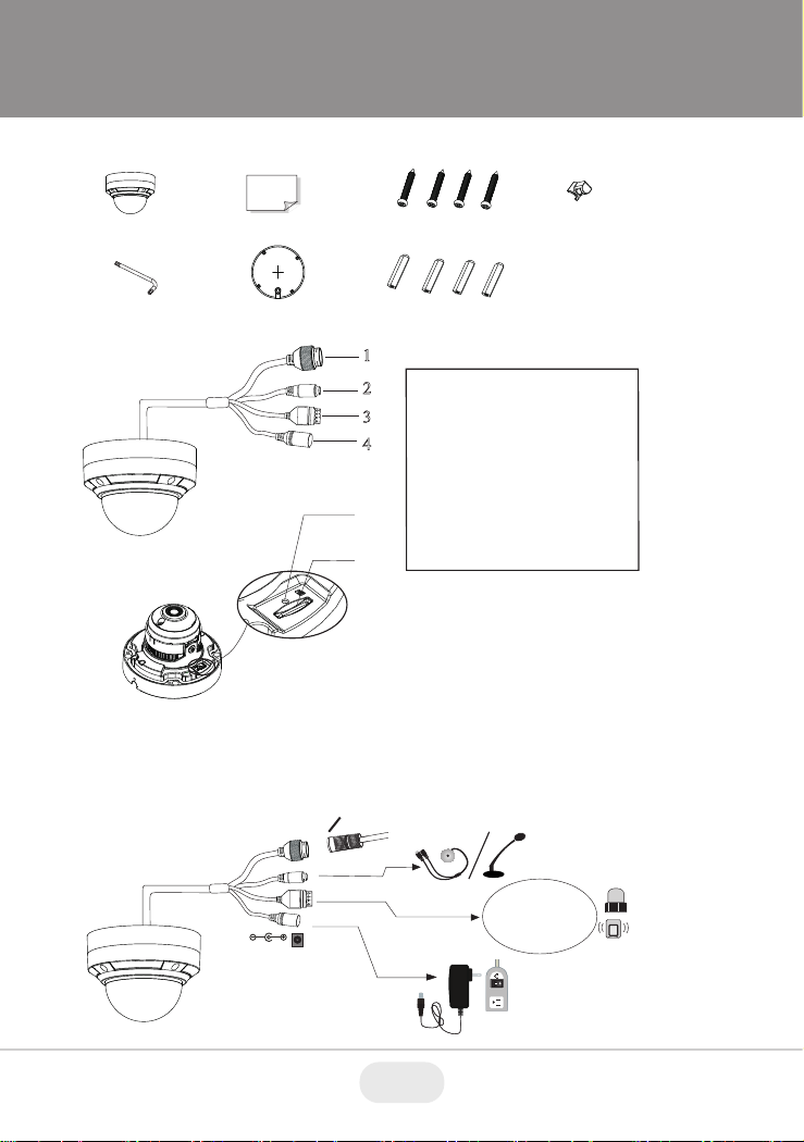
Components and Accessories
Cable Connections
Overview
First connect the Waterproof Cap to an Ethernet patch cable, then
connect the cameras ethernet adaptor. If not powering the camera with
PoE, also connect the power Cable to an approved 12VDC Power
Supply.
Cam era
Qui ck
sta rt gui de
Pla stic
plu g
× 4
Dri ll tem plate
Rub ber plu g
Scr ewdri ver
4 tappi ng sc rews PA 4×2
6
5
Res et
1
2
3
4
AL
ARM
4 3 2 1
DC12V
ALA
R
M
4 3 2 1
1--A L M -C O M
2--A L M -O P E N
3--A L M -I N A
4--A L M -G N D
Etherne t connect or
Audio inp ut connec tor
Alarm inp ut/outp ut
Power connec tor
Reset
Micro SD Ca rd Slot
1
2
3
4
5
6
Weather Resistant Security Cap
2 3
Page 3
Installation
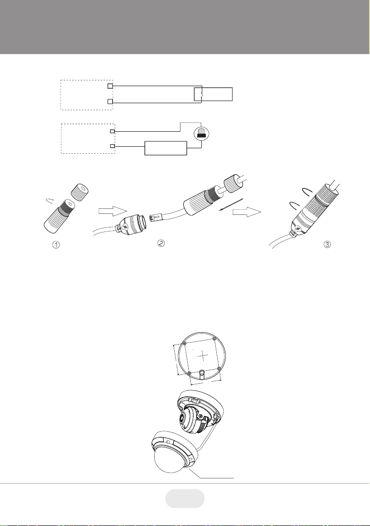
Weather Resistant Network Coupler
1. Loosen the nut from the Weather Resistant Network Coupler.
2. Run ethernet cable through coupler, then attach a RJ-45 connector.
3. Tighten the nut and coupler for a weather resistant seal.
Before beginning installation, make sure that the wall or ceiling is
strong enough to withstand 3 times the weight of the camera. The
mounting steps are as follows:
2. Loosen the screws to open
the lower dome and then
loosen the lock screw to
remove the mounting base.
1. Attach the drill template to
the place where you want to
install the camera, then drill
the screw holes and 1 cable
hole according to the drill
template.
2.92”
2.92”
Lower D om e
A lar m
P ower S our ce
IPC
A L AR M -C O M
A L AR M -O PE N
C onnecti ng A lar m I nput/O utput
A lar m I nput
A lar m O utput
+
+
-
-
Senso r
IPC
A L AR M -I N
A L AR M -G ND
3
4
1
2
3
Page 4

5. Install the dome bubble on the camera with the included screws,
then carefully remove the protective film to complete the installa-
tion.
4. Before adjusting the three-axis camera mount, preview the
camera on a monitor, then adjust as necessary achieve the
optimum viewing angle.
Rotation 0°~355°
Pan 0°~355°
Tilt 0°~67°
Installation
5. Install the dome bubble on the camera with the included screws,
then carefully remove the protective film to complete the installa-
tion.
4. Before adjusting the three-axis camera mount, preview the
camera on a monitor, then adjust as necessary achieve the
optimum viewing angle.
Rotation 0°~345°
Pan 0°~345°
Tilt 0°~77 °
3. Route the cables and
connect the power & video
cables, use the rubber plug
to fill the gap of the mounting
base. then secure the
mounting base to the ceiling
or wall with screws.
Rubbe r Pl ug
5. Install the dome bubble on the camera with the included screws,
then carefully remove the protective film to complete the installation.
4. Before adjusting the three-axis camera mount, preview the
camera on a monitor, then adjust as necessary achieve the
optimum viewing angle.
Rotation 0°~345°
Pan 0°~345°
Tilt 0°~77 °
3. Route the cables and
connect the power & video
cables, use the rubber plug
to fill the gap of the mounting
base. then secure the
mounting base to the ceiling
or wall with screws.
Rubbe r Pl ug
4 5
Page 5

LAN Configuration
The camera can be accessed on the local network either using the
IP-Tool or directly in a web browser.
Accessing the Camera Using the IP-Tool
1. Make sure the camera and PC are connected to the LAN.
2. Locate the IP-Tool installer at www.
vitekcctv.com/Downloads/Soft-
ware/Transcendent-IPTool_v2.0.2.zip
, then install on the PC. Open
the installed application.
3. Modify the IP address. The default IP address is 192.168.226.201.
Click the information of the camera listed in the above table to show
the network information on the right side. Modify the IP address and
gateway of the camera and make sure its network address is in the
same local network segment as the computer’s. Please modify the
IP address of your device according to the practical situation.
For example, the IP address of your computer
is 192.168.13.4. So the IP address of the
camera shall be changed to 192.168.13.X.
After modification, please input the password
of the administrator and click “Modify” button
to modify the setting.
** Default admin password: “123456".
MENU
IPC
Net work Cab le Net work Cab le
Switc h
Route r
Compu ter
LAN Configuration
The camera can be accessed on the local network either using the
IP-Tool or directly in a web browser.
Accessing the Camera Using the IP-Tool
1. Make sure the camera and PC are connected to the LAN.
2. Locate the IP-Tool installer at www.
vitekcctv.com/Downloads/Soft-
ware/Transcendent-IPTool_v2.0.2.zip
, then install on the PC. Open
the installed application.
3. Modify the IP address. The default IP address is 192.168.226.201.
Click the information of the camera listed in the above table to show
the network information on the right side. Modify the IP address and
gateway of the camera and make sure its network address is in the
same local network segment as the computer’s. Please modify the
IP address of your device according to the practical situation.
For example, the IP address of your computer
is 192.168.13.4. So the IP address of the
camera shall be changed to 192.168.13.X.
After modification, please input the password
of the administrator and click “Modify” button
to modify the setting.
** Default admin password: “123456".
MENU
IP Camera
Net wor k C abl e Net wor k C abl e
Switc h
Route r
Compu ter
5
Page 6

4. Double-click the IP address and then the system will pop up the web
browser to connect IP-CAM . The IE browser will download the
Active X control. After downloading, a login window will pop up as
shown below:
Input the user name and password to log in.
Default user name: admin / Default password: 123456.
Directly Access Through a Web Browser
The default network settings are as shown below:
IP address: 192.168.226.201 HTTP: 80
Subnet Mask: 255.255.255.0 Data Port: 9008
Gateway: 192.168.226.1
You may use the above default settings when you log in the camera for
the first time.
1. Manually set the IP address of the PC. The network segment should
be the same as the default settings of IP-CAM. Open the network
and share center. Click “Local Area Connection” to pop up the
following window.
Select “Properties” and then select Internet protocol according to the
actual situation (for example: IPV4). Next, click “Properties” button to
set the network of the PC.
4. Double-click the IP address and then the system will pop up the web
browser to connect IP-CAM . IE browser will download the Active X
control. After downloading, a login window will pop up as shown
below:
Input the user name and password to log in.
Default user name: admin / Default password: 123456.
Directly Access Through a Web Browser
The default network settings are as shown below:
IP address: 192.168.226.201 HTTP: 80
Subnet Mask: 255.255.255.0 Data Port: 9008
Gateway: 192.168.226.1
You may use the above default settings when you log in the camera for
the first time.
1. Manually set the IP address of the PC. The network segment should
be the same as the default settings of IP-CAM. Open the network
and share center. Click “Local Area Connection” to pop up the
following window.
Select “Properties” and then select Internet protocol according to the
actual situation (for example: IPV4). Next, click “Properties” button to
set the network of the PC.
6 7
Page 7

2. Open the IE Browser and input the default address of IP-CAM and
confirm. The IE browser will download Active X control.
3. After downloading Active X control, the login dialog box will pop up.
4. Input the default username and password and then enter to view.
WAN Configuration
Access the camera by the router or virtual server for example.
1. Make sure the camera is connected to the LAN; Then log into the
camera via LAN and go to System Congfig→Network Config→Port
menu to set up the port number.
2. Enter System Config→Network Config→IP Address menu to modify
the IP address.
4. Open the web browser and input its WAN IP and HTTP port to
access the IP-CAM.
3. Go to the router’s management interface through IE browser to
forward the IP address and port of IP-CAM in the “Virtual Server”.
5. For additional setup, features and functions, please scan
the QR code on the front page of this quick guide and
download the complete manual.
7
Page 8

LIMITED PRODUCT WARRANTY
VITEK products carry a three (3) year limited warranty. VITEK warrants
to the purchaser that products manufactured by VITEK are free of any
rightful claim of infringement or the like, and when used in the manner
intended, will be free of defects in materials and workmanship for a
period of three (3) years, or as otherwise stated above, from the date of
purchase by the end user. This warranty is nontransferable and extends
only to the original buyer or end user customer of a VITEK Authorized
Reseller.
The product must have been used only for its intended purpose, and
not been subjected to damage by misuse, willful or accidental damage,
caused by excessive voltage or lightning.
The product must not have been tampered with in any way or the
guarantee will be considered null and void.
This guarantee does not affect your statutory rights.
Contact your local VITEK Reseller should servicing become necessary.
VITEK makes no warranty or guarantee whatsoever with respect to
products sold or purchased through unauthorized sales channels.
Warranty support is available only if product is purchased through a
VITEK Authorized Reseller.
28492 CONSTELLATION ROAD VALENCIA, CA 91355
WWW.VITEKCCTV.COM
Version 1.0
Nov. 2019
 Loading...