

Page 1

SAGA “ST” Series
VITEK
• The Industry’s only MPEG4 Compression with Non-Conditional Refresh
• 120 IPS Recording and Real-Time 480 IPS Display
• MPEG-4 Compression
• Up to 42 HDD support: 1.5 Terabyte Internal Storage (2x - 750GB HDD) and Up to 30
Terabytes External Storage (4x - 10 HDD Expansion bay units)
4, 8, and 16 Channel Digital
Video Recorders
• 4 Channel audio
• 2-Way communication over the internet via Remote Client Software
• Multi-site remote client
• Built-in DVD/RW drive
• Accepts 4 External (VT-XHD10) HDD Bays for an Additional 40 Hard Drives
• Block Search Function Retrieves Lost Files, Even from Damaged Hard Drives
• Embedded Linux OS
• Dynamic IP support (DDNS)
• Maximum File Size of 6K (CIF), 11K (Half D1), 20K (D1)
• Continuous, Motion, Alarm, V-Loss, Scheduled recording modes
• Numerous search modes: Calendar, Search & Copy, Time, Event, Block, File, Bookmark &
Log
• Multi-site Monitoring for a maximum of 16 Independent DVRs and a maximum of 256
Cameras
• Notification e-mail to up to 10 accounts on Motion, Alarm, V-Loss, HDD Fail
• Pentaplex Plus: Record, Playback, Network Transmission, Mirror, Backup and Live Viewing
• Backup to External HDD, CD-R, CD-RW, DVD-RW, DVD+RW, USB Memory Stick
• Control up to 16 DVRs via Keyboard or IR Remote control
Page 2

SAGA “ST” Series
PACKAGE CONTENTS
Prior to installation of the SAGA series DVR, please verify that the packaging contains
the following contents:
1. One SAGA “ST” series DVR
2. One AC Adaptor
3. One Power Cable
4. One Remote Controller
5. DVR Viewer Program CD
6. This Instruction Manual.
7. Two AAA batteries.
8. Rack Mount Ears and screws.
If any of the contents are missing, please contact the Vitek Customer Help Desk
immediately.
1
Page 3
SAGA “ST” Series
G
RISK OF ELECTRICAL SHOCK WARNING
WARNIN
TO REDUCE THE RISK OF FIRE OR ELECTRIC SHOCK, DO NOT EXPOSE THIS PRODUCT TO RAIN
OR MOISTURE. DO NOT INSERT ANY METALLIC OBJECTS THROUGH THE VENTILATION GRILLS OR
OTHER OPENINGS ON THE EQUIPMENT.
CAUTION
EXPLANATION OF GRAPHICAL SYMBOLS
The ligh tning flash with ar rowh ead symb ol, with in a n equ ilate ral triangle , is inte nded to
alert th e user to th e presence of uninsu lated "dange rous volt age" within the produc t's
enclosure that may be of sufficient magnitude to constitute a risk of electric shock to
persons.
The exclamation point within an equilateral triangle is intended to alert the user to the
presenc e of im por ta nt op er at ing an d m ai nte na nce (se r vici ng ) in s tru ctio n in t he literature
accompanying the product.
2
Page 4

SAGA “ST” Series
DISCLAIMER
While every effort has been made to ensure that the information contained in this
guide is accurate and complete, no liability can be accepted for any errors or
omissions.
Vitek Industrial Video Products, Inc. reserves the right to change the
specifications of the hardware and software described herein at any time without
prior notice.
No part of this guide may be reproduced, transmitted, transcribed, stored in a
retrieval system, or translated into any language in any form, by any means,
without prior written permission of Vitek Industrial Video Products, Inc.
Vitek makes no warranties for damages resulting from corrupted or lost data due
to a mistaken operation or malfunction of the Digital Video Recorders, the
software, personal computers, peripheral devices, or unapproved/unsupported
devices.
Trademark Acknowledgements
Saga Series Digital Video Recorders are trademarks of Vitek Industrial Video
Products, Inc.
Other names and products not mentioned here may be registered trademarks or
trademarks of their respective companies.
Copyright ©2007 Vitek Industrial Video Products, Inc. All rights reserved.
3
Page 5

SAGA “ST” Series
FCC NOTICE
Saga Series Digital Video Recorders, VT-ST420, VT-ST820, VT-ST1620
These devices comply with Part 15 of the FCC Rules. Operation is subject to the
following two conditions;
1. These devices may not cause harmful interference, and
2. These devices must accept any interference received, including interference that
may cause undesired operation.
Note: This equipment has been tested and found to comply with the limits for Class B
digital devices, pursuant to Part 15 of the FCC rules. These limits are designed to
provide reasonable protection against harmful interference in a residential installation.
These equipments generate, use and can radiate radio frequency energy and, if not
installed and used in accordance with the instructions, may cause harmful interference
to radio communications. However, there is no guarantee that interference will not
occur in a particular installation. If this equipment does cause harmful interference to
radio or television reception, which can be determined by turning the equipment off and
on, the user is encouraged to try to correct the interference by on or more of the
following measures:
• Reorient or relocate the receiving antenna.
• Increase the separation between the equipment and receiver.
• Connect the equipment to an outlet on a circuit different from that to which the
receiver is connected.
• Consult the dealer or an experienced technician for help.
Do not make any changes or modifications to the equipments unless otherwise
specified in the manual. If such changes or modifications should be made, you could be
required to stop operation of the equipment.
Vitek Industrial Video Products, Inc.
28492 Constellation Road
Valencia, CA 91355
Phone: (888) VITEK-70 / (661) 294 – 8043
Fax: (661) 294 – 8044
www.vitekcctv.com | Sales@vitekcctv.com
Canadian Radio Interference Regulations
This is a Class A apparatus complies with Canadian ICES-003.
Cet Appareil numérique de la Classe A conforme à la norme NMB-003 du Canada.
4
Page 6

SAGA “ST” Series
Read this First
Test Sessions
Before you try to record important subjects, we highly recommend that you make
several test sessions to ensure that the Digital Video Recorder is operating and being
operated correctly. Please note that Vitek Industrial Video Products, Inc., its
subsidiaries and affiliates, and its distributors are not liable for any consequential
damages arising from any malfunction of the Digital Video Recorder or its accessories.
The Privacy act of 1974 (5 U.S.C. § 552a)
Please note that the Digital Video Recorders are intended for surveillance use and
should never be used in a manner that invades other people’s privacy or contravenes
international or domestic privacy act and its regulations. Please be advised that in
certain cases the monitoring of individuals, private properties, or commercial properties
may contravene legal rights of such individuals even if the images were recorded for
personal use.
Warranty Limitations
This equipment’s warranty is only effective in the country of sale. If a problem arises
while the Digital Video Recorder is in use abroad, please convey it back to the country
of sale before proceeding with a warranty claim to Vitek customer help desk.
5
Page 7

Before using the Digital Video Recorder, please ensure that you read and
understand the safety precautions described below. Always ensure that the
Digital Video Recorder is operated correctly.
The safety precautions noted on the following pages are intended to instruct you
in the safe and correct operation of the Digital Video Recorder and its
accessories to prevent injuries or damage to the self, other persons and
equipment.
In this Instruction Manual, the term “Digital Video Recorder”, “equipment” and
“device” refers primarily to the Digital Video Recorder and its accessories such
as power supply and its remote controller.
WARNINGS
Do not cover the ventilation opening or slots on the outer casing. To prevent the
Digital Video Recorder from overheating, provide at least two inches of air space
around the vent and the slots.
Do not drop metallic parts through slots. This could permanently damage the
Digital Video Recorder. Immediately turn the Digital Video Recorder’s power off
or unplug the power cord from the power outlet. Contact a qualified service
personnel authorized by the equipment distributor or a Vitek customer help desk.
Do not attempt to disassemble or alter any part of the equipment that is not
expressly described in this guide. Disassembly or alteration may result in high
voltage electric shock. Internal inspections, alterations and repairs should be
conducted by qualified service personnel authorized by the equipment distributor
or Vitek customer help desk.
Stop operating the equipment immediately if it emits smoke or noxious fumes.
Failure to do so may result in fire or electrical shock. Immediately turn the
Digital Video Recorder’s power off, remove the power cable from the power
outlet. Confirm that smoke and fume emissions have ceased. Please consult
the Digital Video Recorder reseller or the Vitek customer help desk.
Stop operating the equipment if a heavy object is dropped or the casing is
damaged. Do not strike or shake. Failure to do so may result in fire or electrical
shock. Immediately turn the Digital Video Recorder’s power off or unplug the
power cord from the power outlet. Please consult the Digital Video Recorder
reseller or the Vitek customer help desk.
SAGA “ST” Series
SAFETY PRECAUTIONS
6
Page 8

SAGA “ST” Series
Do not allow the equipment to come into contact with, or become immersed in,
water or other liquids. Do not allow liquids to enter the interior. The Digital
Video Recorder has not been waterproofed. If the exterior comes into contact
with liquids or salt air, wipe it dry with a soft, absorbent cloth. In the event that
the water or other foreign substances enter the interior, immediately turn the
Digital Video Recorder’s Power off or unplug the power cord from the power
outlet. Continued use of the equipment may result in fire or electrical shock.
Please consult the Digital Video Recorder reseller or the Vitek customer help
desk.
Do not use substances containing alcohol, benzene, thinners or other flammable
substances to clean or maintain the equipment. The use of these substances
may lead to fire. Use a dry cloth on a regular periodic basis and wipe away the
dust and dirt that collects on the device. In dusty, humid or greasy environments,
the dust that collects around the ventilation or the slots on the outer casing over
long periods of time may become saturated with humidity and short-circuit,
leading to fire.
Do not cut, damage, alter or place heavy items on the power cord. Any of these
actions may cause an electrical short circuit, which may lead to fire or electrical
shock.
Do not handle the device or power cord with wet hands. Handling it with wet
hands may lead to electrical shock. When unplugging the cord, ensure that you
hold the solid portion of the plug. Pulling on the flexible portion of the cord may
damage or expose the wire and insulation, creating the potential for fires or
electrical shocks.
Use only the recommended power accessories. Use of power sources not
expressly recommended for this equipment may lead to overheating, damage tof
the equipment, fire, electrical shock or other hazards.
The supplied power supply and power cord are designed for exclusive use with
the Digital Video Recorder. Do not use it with other products or battery. There
is a risk of fire and other hazards.
Avoid using, placing or storing the equipment in places subject to strong sunlight
or high temperatures, such as a greenhouse or trunk of a car. High
temperatures may also cause deformation of the casing. Ensure that there is
good ventilation when using the equipment.
Do not operate the Digital Video Recorder beyond its specified temperature,
humidity or power source ratings. Do not use the Digital Video Recorder in an
extreme environment such as in high temperature or high humidity. Use the
device at temperatures within 41°F - 104°F and humidity below 90%.
7
Page 9

SAGA “ST” Series
PREVENTING MALFUNCTION
Avoid Strong Magnetic Fields. Never place the Digital Video Recorder in close
proximity to electric motors or other equipment generating strong
electromagnetic fields. Exposure to strong magnetic fields may cause
malfunctions or corrupt image data.
Avoid Condensation Related Problems. Moving the equipment rapidly between
hot and cold temperatures may cause condensation (water droplets) to form on
its external and internal surfaces. You can avoid this by placing the equipment
in an airtight, re-sealable plastic bag and letting it adjust to temperature changes
slowly before removing it from the bag.
If Condensation forms inside the Digital Video Recorder. Stop using the
equipment immediately if you detect condensation. Continued use may damage
the equipment. Remove the power cord from the power outlet and wait until the
moisture evaporates completely before resuming use.
8
Page 10

SAGA “ST” Series
TABLE OF CONTENTS
PACKAGE CONTENTS............................................................................................1
RISK OF ELECTRICAL SHOCK WARNING ............................................................2
DISCLAIMER............................................................................................................ 3
FCC NOTICE............................................................................................................ 4
Read this First...........................................................................................................5
Test Sessions ...........................................................................................................5
The Privacy act of 1974 (5 U.S.C. § 552a) ...............................................................5
Warranty Limitations.................................................................................................5
SAFETY PRECAUTIONS.........................................................................................6
WARNINGS..............................................................................................................6
PREVENTING MALFUNCTION................................................................................8
TABLE OF CONTENTS............................................................................................9
I. FEATURE HIGHLIGHTS .....................................................................................14
1.1 OPERATION.....................................................................................................14
1.2 RECORDING....................................................................................................14
1.3 PLAY................................................................................................................. 15
1.4 NETWORK........................................................................................................15
1.5 BACKUP...........................................................................................................15
1.6 STORAGE ........................................................................................................16
1.7 SYSTEM........................................................................................................... 16
II. SAGA “ST” SERIES DIGITAL VIDEO RECORDER LAYOUT............................ 17
2.1 FRONT PANEL LAYOUT..................................................................................17
2.2 REAR PANEL LAYOUT....................................................................................20
2.3 IR REMOTE CONTROLLER.............................................................................23
2.4 MOUSE CONTROL..........................................................................................25
III. INSTALLATION AND CONNECTIONS .............................................................26
3.1 CONNECTIONS LAYOUT................................................................................ 26
3.2 VT-XHD10U...................................................................................................... 27
3.3 EXTERNAL TERMINAL CONNECTION...........................................................28
3.3.1 RS-485 .................................................................................................... 28
3.3.2 TIME ADJUST.........................................................................................28
3.3.3 RELAY OUTPUT..................................................................................... 29
3.3.4 ALARM SENSOR INPUT ........................................................................ 29
3.3.5 VGA PIN LAYOUT...................................................................................30
3.3.6 RS-232C PIN LAYOUT............................................................................30
IV. BASIC OPERATION.......................................................................................... 31
4.1 MAIN SCREEN.................................................................................................31
4.2 STATUS SCREEN............................................................................................32
4.3 LIVE VIEW........................................................................................................ 34
4.3.1 LIVE VIEW MODE SEQUENCE..............................................................34
4.3.1.1 VT-ST1620.....................................................................................34
4.3.1.2 VT-ST820....................................................................................... 35
4.3.2 FULL SCREEN DISPLAY........................................................................35
4.3.3 AUTOMATIC SEQUENCE ...................................................................... 36
9
Page 11

SAGA “ST” Series
4.4 FREEZE............................................................................................................36
4.4.1 SINGLE SCREEN VIEW MODE.............................................................. 37
4.4.2 MULTI SCREEN VIEW MODE................................................................37
4.5 ZOOM...............................................................................................................38
4.6 PICTURE-IN-PICTURE.....................................................................................39
4.7 SPOT MONITOR..............................................................................................40
4.8 BASIC RECORDING ........................................................................................41
4.9 BASIC PLAYBACK...........................................................................................42
4.9.1 PLAY / REVERSE PLAY / PAUSE / STOP .............................................42
4.9.2 FAST FORWARD / REWIND ..................................................................43
4.9.3 PICTURE-BY-PICTURE..........................................................................43
4.9.4 SLOW......................................................................................................44
4.9.5 LOOP PLAYBACK...................................................................................44
4.9.6 BOOKMARK............................................................................................45
4.9.7 AUDIO PLAYBACK .................................................................................46
V. ADVANCED OPERATION..................................................................................47
5.1 BACKUP...........................................................................................................47
5.1.1 CD-RW / DVD-RW / DVD+RW................................................................47
5.1.2 CD-R........................................................................................................50
5.1.3 USB FLASH MEMORY............................................................................52
5.1.4 EXTERNAL HARD DISK DRIVE .............................................................54
5.1.5 COPY STATUS .......................................................................................54
5.1.6 COPY STOP............................................................................................ 55
5.2 PAN / TILT / ZOOM CAMERA CONTROL........................................................ 56
5.2.1 BASIC PAN / TILT / ZOOM CONTROL................................................... 56
5.2.2 CREATING AND MOVING TO PRESET POINTS...................................57
5.3 ADVANCED RECORDING............................................................................... 57
5.3.1 ALARM RECORDING ............................................................................. 58
5.3.2 VIDEO LOSS RECORDING....................................................................58
5.3.3 MOTION RECORDING ........................................................................... 59
5.4 ADVANCED PLAYBACK..................................................................................59
5.4.1 CALENDAR SEARCH.............................................................................59
5.4.2 SEARCH & COPY................................................................................... 61
5.4.3 TIME SEARCH........................................................................................63
5.4.4 EVENT SEARCH..................................................................................... 64
5.4.5 BLOCK SEARCH.....................................................................................66
5.4.6 FILE SEARCH......................................................................................... 68
5.4.7 BOOKMARK SEARCH............................................................................69
5.4.8 TEXT SEARCH........................................................................................70
5.4.9 LOG FILE SEARCH.................................................................................72
VI. DVR MENU .......................................................................................................75
6.1 QUICK SETUP..................................................................................................76
6.1.1 QUICK SETUP ........................................................................................76
6.1.2 IMAGE SIZE............................................................................................76
6.1.3 RECORD FRAME....................................................................................77
6.1.4 EVENT.....................................................................................................77
10
Page 12

SAGA “ST” Series
6.1.5 PRE-RECORD TIME...............................................................................77
6.1.6 POST-RECORD TIME.............................................................................78
6.1.7 IMAGE QUALITY..................................................................................... 78
6.1.8 AUDIO RECORD.....................................................................................78
6.1.9 REMOTE CONTROL ID..........................................................................78
6.2 SCREEN SETUP..............................................................................................79
6.2.1 AUTO SEQUENCE..................................................................................79
6.2.2 DISPLAY .................................................................................................81
6.2.3 TITLE.......................................................................................................83
6.2.4 MULTI-SCREEN ...................................................................................... 83
6.2.5 COVERT.................................................................................................. 84
6.2.6 SPOT.......................................................................................................85
6.2.7 CAMERA.................................................................................................86
6.3 RECORD ..........................................................................................................88
6.3.1 RECORD SETUP.................................................................................... 88
6.3.2 RECORD PROGRAM..............................................................................90
6.3.3 IMAGE QUALITY..................................................................................... 94
6.3.4 AUDIO RECORD.....................................................................................94
6.3.5 REPEAT RECORD..................................................................................95
6.3.6 PLAY MODE............................................................................................ 95
6.3.7 BACKUP MODE...................................................................................... 96
6.3.8 HOLIDAY.................................................................................................96
6.4 EVENT.............................................................................................................. 97
6.4.1 MOTION DETECTION.............................................................................97
6.4.2 EVENT SCREEN MODE.........................................................................99
6.4.3 EVENT CHECK.......................................................................................99
6.4.4 EVENT MESSAGE.................................................................................. 99
6.4.5 EVENT MESSAGE RESET...................................................................100
6.4.6 EVENT BUZZER ...................................................................................100
6.4.7 SENSOR INPUT.................................................................................... 100
6.4.8 RELAY OUTPUT................................................................................... 101
6.5 SYSTEM......................................................................................................... 102
6.5.1 HARD DISK DRIVE............................................................................... 102
6.5.1.1 HDD configuration........................................................................102
6.5.1.2 Rec HDD initialize ........................................................................ 103
6.5.1.3 Backup HDD initialize...................................................................104
6.5.2 CLOCK..................................................................................................104
6.5.2.1 Date & Time .................................................................................104
6.5.2.2 Time Adjust ..................................................................................105
6.5.3 VIDEO STANDARD...............................................................................106
6.5.4 LANGUAGE........................................................................................... 107
6.5.5 REMOTE CONTROL ID........................................................................107
6.5.6 KEY ECHO............................................................................................107
6.5.7 ADVANCED SETUP..............................................................................108
6.5.7.1 Password Check.................................................................................108
6.5.7.2 Set Password .....................................................................................108
11
Page 13

SAGA “ST” Series
6.5.7.3 User Authority...............................................................................109
6.5.7.4 DVR Menu Setup ......................................................................... 109
6.5.7.4.1 Menu Initialize ...........................................................................109
6.5.7.4.2 Load menu from file................................................................... 110
6.5.7.4.3 Save menu to file.......................................................................110
6.5.9 FIRMWARE UPGRADE ........................................................................ 111
6.6 LINK................................................................................................................113
6.6.1 NETWORK............................................................................................113
6.6.2 RS-232C................................................................................................115
6.6.3 RS-485 .................................................................................................. 116
6.6.4 PTZ........................................................................................................118
6.6.5 E-MAIL...................................................................................................119
6.6.5.1 Send e-mail.................................................................................. 119
6.6.5.2 SMTP server ................................................................................120
6.6.5.3 DVR e-mail address.....................................................................120
6.6.5.4 User ID.........................................................................................121
6.6.5.5 Password......................................................................................121
6.6.5.6 E-mail address 1 through 10 ........................................................122
VII. SEARCH.........................................................................................................123
BACK....................................................................................................................123
VIII. COPY ............................................................................................................123
IX. EXIT ................................................................................................................124
9.1 SAVE ONLY....................................................................................................124
9.2 SAVE AND EXIT.............................................................................................124
9.3 EXIT WITHOUT SAVE .................................................................................... 125
X. CLIENT PROGRAM.........................................................................................126
10.1 SYSTEM REQUIREMENT............................................................................126
10.2 INSTALLING THE DVR VIEWER.................................................................126
10.3 DVR VIEWER - LAYOUT..............................................................................128
10.4 DVR VIEWER - LIVE MODE.........................................................................146
10.5 DVR VIEWER – PLAYBACK MODE............................................................. 148
10.5.1 TIME SEARCH.................................................................................... 149
10.5.2 CALENDAR SEARCH.........................................................................150
10.5.3 EVENT................................................................................................. 151
10.5.4 TEXT ................................................................................................... 152
10.5.5 BLOCK ................................................................................................ 154
10.6 DVR PLAYER – SETUP ...............................................................................156
10.6.1 QUICK SETUP ....................................................................................157
10.6.2 SCREEN.............................................................................................. 158
10.6.2.1 Auto Sequence...........................................................................158
10.6.2.2 Display .......................................................................................158
10.6.2.4 Title ............................................................................................159
10.6.2.5 Multiscreen.................................................................................160
10.6.2.6 Covert......................................................................................... 160
10.6.2.6 Spot............................................................................................160
10.6.3 RECORD.............................................................................................161
12
Page 14

SAGA “ST” Series
10.6.3.1 Record........................................................................................ 161
10.6.3.2 Record Program.........................................................................161
10.6.3.3 Holiday .......................................................................................162
10.6.4 EVENT................................................................................................. 162
10.6.4.1 Event..........................................................................................162
10.6.4.2 Motion Detection ........................................................................ 162
10.6.4.3 Sensor Input............................................................................... 163
10.6.4.4 Relay Output .............................................................................. 163
10.6.5 SYSTEM..............................................................................................164
10.6.5.1 System .......................................................................................164
10.6.5.2 HDD .......................................................................................... 164
10.6.5.3 CLOCK....................................................................................... 164
10.6.5.3 PASSWORD .............................................................................. 165
10.6.6 LINK.....................................................................................................165
10.6.6.1 Network...................................................................................... 165
10.6.6.2 RS-232C.....................................................................................165
10.6.6.3 RS-485.......................................................................................166
10.6.6.4 PTZ ............................................................................................166
10.6.6.5 E-mail.........................................................................................166
10.6.7 DOWNLOAD .......................................................................................167
XI. SPECIFICATIONS...........................................................................................169
11.1 VT-ST420......................................................................................................169
11.2 VT-ST820......................................................................................................171
11.3 VT-ST1620....................................................................................................173
XII. TECHNICAL SUPPORT................................................................................. 175
APPENDIX I.......................................................................................................... 176
TIME ZONE LISTING ........................................................................................... 176
INDEX...................................................................................................................178
NOTES .................................................................................................................181
13
Page 15

SAGA “ST” Series
I. FEATURE HIGHLIGHTS
1.1 OPERATION
A. PENTAPLEX PLUS FUNCTION
Simultaneous record, playback, mirror, backup, network transmission and partial live
view.
B. REAL-TIME DISPLAY
Each channel is displayed at 30pps during live monitoring.
C. DIGITAL ZOOM
Up to 2 times digital zoom display.
D. PICTURE-IN-PICTURE
E. EASY OPERATION
Control through the front panel buttons, IR remote controller, external joystick
keyboard controller and USB 2.0 compliant mouse.
F. COVERT MODE
Hide channels in live, playback and network transmission.
1.2 RECORDING
A. RECORDING
Maximum recording speed of 120 pps in VT-ST1620, VT-ST820 and VT-ST420.
B. MULTI-QUALITY / MULTI SPEED RECORDING
Recording in different recording qualities and record speed.
C. MULTIPLE RECORDING OPTIONS
Manual, event and schedule recording.
D. VERSATILE EVENT RECORDING
Motion, alarm and video loss recording option with dedicated pre and post recording
per channel.
E. AUDIO RECORDING
4 channel audio recording.
14
Page 16

SAGA “ST” Series
1.3 PLAYBACK
A. MULTI-SCREEN
Single, quad, 6, 7, 9, 10, 13 and 16 channel playback.
B. VERSATILE SEARCH OPTIONS
Calendar, search & copy, timeline, event, block, file and bookmark search.
C. PREVIEW
Snapshot of search date and time in search mode.
1.4 NETWORK
A. MULTI-SITE LIVE MONITORING
Monitor up to 16 DVRs, or up to 256 cameras simultaneously.
B. REMOTE PLAYBACK
Review recorded data from the client software with fast forward and rewind, slow
and pause.
C. REMOTE CONTROL
Remotely control the DVR as if pressing the front buttons or the IR remote controller.
D. REMOTE SETUP
Configure all DVR settings remotely from the client software.
E. FLEXIBLE NETWORK CONNECTIONS
Static and dynamic IP address supported along with proprietary DDNS support.
F. 2-WAY AUDIO COMMUNICATION
Communicate verbally between the DVR and the client software.
1.5 BACKUP
A. DVD-RW / CD-RW
Built-in DVD-RW optical drive enables easy backup to DVD-RW or CD-RW. Data
retrieval is made simple with a mini-viewer that application is automatically included
on disks burned with a SAGA DVR.
B. USB 2.0
Three available USB 2.0 ports allow the use of numerous USB 2.0 backup devices
including VT-XHD10U external HDD add-on bays, individual external hard drives,
external optical drives and USB memory sticks.
C. DATA REDUNDANCY / EVENT COPY ONLY
Flexible hard drive configuration allows data redundancy or backup event data only.
15
Page 17

SAGA “ST” Series
1.6 STORAGE
A. GENEROUS STORAGE CAPACITY
Two available internal hard drive bays allow up to 1.5 terabyte of storage and
optional removable hard drive bay allows an additional 750 gigabytes of storage, for
a maximum of 2.25 terabyes of storage.
B. HARD DRIVE EXPANSION BAY (VT-XHD10U)
Up to four VT-XHD10U hard drive expansion bays can be connected to the DVR.
Each expansion bay is capable of supporting up to ten hard drives, totaling 30
terabytes of additional storage.
C. DATA REDUNDANCY / EVENT COPY ONLY
The hard drives in the expansion bays can also be configured to be data redundant
or event copy only.
1.7 SYSTEM
A. 2 INDEPENDENT WATCHDOGS
Reliable hardware and software watchdogs that monitor the system stability at all
times.
B. EASY UPDATE
Easy update / upgrade via USB 2.0 compliant memory stick or through the client
program.
C. SIMULTANEOUS MULTIPLE VIDEO OUTPUT
a) Composite BNC main monitor output
b) VGA main monitor output
c) S-Video Output
d) Single-channel spot monitor output
D. MULTIPLE LANGUAGE SUPPORT
Available in English, Korean, Japanese, Chinese, Polish, Spanish and Russian.
16
Page 18

SAGA “ST” Series
II. SAGA “ST” SERIES DIGITAL VIDEO RECORDER LAYOUT
2.1 FRONT PANEL LAYOUT
11 12
1. AUDIO SELECT
This button selects the recorded audio channel when in multiple display mode.
Press the button repeatedly to toggle between audio channels 1 through 4.
2. NUMERIC BUTTONS / CHANNEL SELECT
a) Selects a specific channel number to be displayed in full screen.
b) Enter the numeric password when prompted.
3. SPOT MONITOR / ESC
a) Activates the spot monitor control.
b) Returns to previous menu screen.
c) Exits from various function and menu screens.
4. MENU / UP DIRECTIONAL BUTTON
a) Accesses the main menu screen.
b) Tilts up in PTZ mode.
c) Navigates up in the menu screen.
d) Moves the zoom box up in zoom mode.
5. LIVE
This button exits the playback mode and returns to the live monitoring mode.
Pressing this button once more will toggle between live and paused playback mode.
6. RECORD
This button starts and stops the recording mode.
7. SLOW / REVERSE PICTURE-BY-PICTURE / CLOSE IRIS
a) Slow playback. Press this button repeatedly to toggle between ½ normal
b) Reverse Picture-by-Picture in Pause mode.
c) Close Iris in PTZ mode.
1 54 3 2 107896
16 14 22
18 23 24 25
15
13 17
192021
playback speed through 128
th
normal playback speed.
17
Page 19

SAGA “ST” Series
8. PLAY / PAUSE / ZOOM OUT
a) Starts the playback of recorded data. By default, the playback starts from the
earliest recording. If the recording has been played back, the playback will start
from where it was left off.
b) Toggles between playback and pause mode.
c) Zoom out in PTZ mode.
9. FAST / FORWARD PICTURE BY PICTURE
a) Fast forward. Press this button repeatedly to toggle between 2X normal
playback speed through 128X normal playback speed.
b) Forward Picture-by-Picture in Pause mode.
10. DIRECTION / OPEN IRIS
a) Change the playback direction.
b) Open Iris in PTZ mode.
11. USB 2.0
The USB 2.0 port can be used to connect to numerous USB 2.0 backup devices
including VT-XHD10U external HDD add-on bays, individual external hard drives,
external optical drives and USB memory sticks.
12. DISPLAY
This button is used to toggle between multiple display modes: 16 channel, 13
channel, 10 channel, 9 channel, 7 channel, 6 channel and 4 channel split screen
display modes.
13. ALARM RESET / LEFT DIRECTIONAL BUTTON
a) Resets the alarm buzzer.
b) Left pans in PTZ mode.
c) Navigates left in the menu screen.
d) Moves the zoom box left in zoom mode.
14. AUTOMATIC SEQUENCE / FOCUS OUT / DECREASE VALUE / SECTION A
a) Activates and deactivates the automatic channel sequence.
b) Focuses out in PTZ mode.
c) Decreases the value of a selection in the menu screen.
d) Sets the starting point for loop playback in playback mode.
15. ENTER / STATUS / HOME
a) Executes the selected function in the menu screen or enters the selected
submenu.
b) Accesses the status window from the main screen.
c) Returns the PTZ camera to “home” mode in PTZ mode.
d) Increases the digital zoom ratio in zoom mode.
18
Page 20

SAGA “ST” Series
16. PIP / LOOP PLAYBACK CLEAR / DOWN DIRECTIONAL BUTTON
a) Activates the picture-in-picture mode.
b) Tilts down in PTZ mode.
c) Navigates left in the menu screen.
d) Moves the zoom box left in zoom mode.
e) Clears the loop playback in playback mode.
17. DIGITAL ZOOM / RIGHT DIRECTIONAL BUTTON
a) Enters digital zoom mode.
b) Pans right in PTZ mode.
c) Navigates right in the menu screen.
d) Moves the zoom box right in zoom mode.
18. FREEZE / FOCUS IN / INCREASE VALUE / SECTION B
a) Freezes the live screen.
b) Focuses in PTZ mode.
c) Increases the value of a selection in the menu screen.
d) Sets the ending point for loop playback in playback mode.
19. COPY / AUTOFOCUS
a) Enters the copy menu screen.
b) Switches the PTZ camera to auto focus mode in PTZ mode.
20. PTZ / BOOKMARK
a) Enters PTZ control mode.
b) Creates a bookmark during playback mode.
21. SEARCH / PRESET
a) Enters the search menu screen
b) Sets the preset positions in PTZ mode
22. FUNCTION
a) Used in conjunction with the “USER” option for Relay 4 of the alarm output.
b) Controls PTZ movement speed in PTZ mode.
23. STATUS LED
Displays the status of the DVR (Standby), HDD read/write and network transmission.
24. IR RECEIVER
Infrared signal receiver for the IR remote controller. Do not block the receiver as a
clear line of sight is required for proper operation.
25. REMOVABLE HDD RACK / DVD-RW
A DVD-RW drive is installed in the front 5.25” expansions bay. A third hard drive
can be added to the DVR by replacing the optical drive with a removable hard drive
rack (sold separately).
19
Page 21
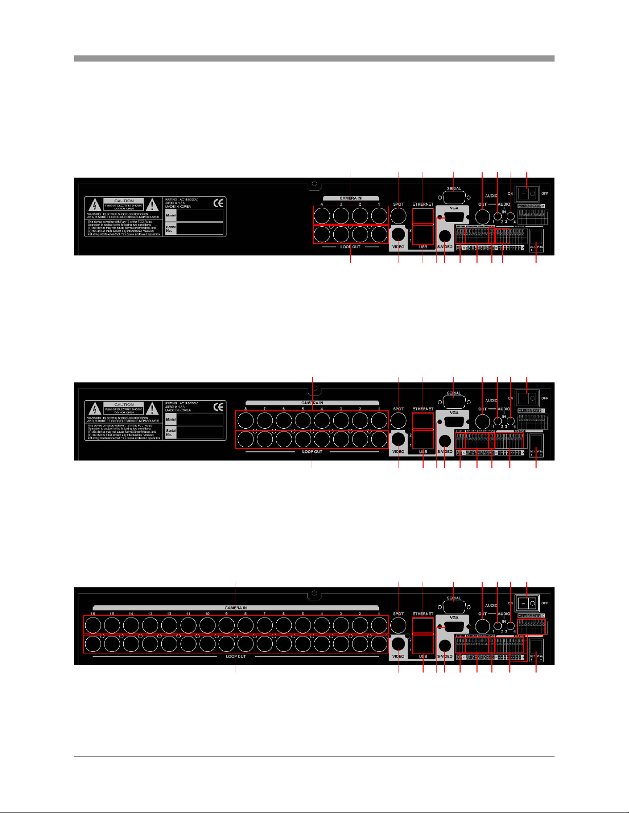
2.2 REAR PANEL LAYOUT
VT-ST420
VT-ST820
SAGA “ST” Series
15 4 32786
109 11 1213 1716 15 14 18
15 4 32786
VT-ST1620
109 11 12 13 16 15 14 1817
1 5 4 32786
109 11 12 13 16 15 14 1817
20
Page 22

SAGA “ST” Series
1. CAMERA INPUT
BNC connectors for composite video signal input.
2. SPOT OUTPUT
Spot monitor BNC connector for composite video signal output.
3. RJ-45 ETHERNET PORT
10/100Base-T RJ-45 port for network connection.
4. RS-232C
Reserved. The RS-232C port can be used to connect a variety of devices to control
the DVR.
5. AUDIO OUTPUT
RCA connector for audio signal output.
6. AUDIO INPUT 1 / 2
1/8” Jack connector for audio channels 1 and 2 input.
7. AUDIO INPUT 3 / 4
1/8” Jack connector for audio channels 3 and 4 input.
8. POWER SWITCH
This switch turns the DVR on or off.
9. CAMERA LOOP OUTPUT
Self-terminating BNC connectors for composite video signal loop output.
10. MAIN MONITOR OUTPUT
BNC connector for main monitor composite video signal output.
11. USB REAR 1 / USB REAR 2
The USB 2.0 ports can be used to connect to numerous USB 2.0 backup devices
including VT-XHD10U external HDD add-on bays, individual external hard drives,
external optical drives and USB memory sticks.
12. VGA OUTPUT
D-sub 15-pin connector for PC monitor out.
13. S-VIDEO OUTPUT
S-video connector for main monitor video signal output.
14. RS-485 TERMINAL BLOCK
Terminal blocks for RS-485.
21
Page 23

SAGA “ST” Series
15. RELAY OUT
Terminal blocks for relay out 1 through 4.
16. TIME SYNCHRONIZATION
Input and Output terminal blocks for time synchronization between DVRs.
17. ALARM INPUT
Alarm input 1 through 4 on VT-ST420, 1 through 8 on VT-ST820 and 1 through 16
on VT-ST1620.
18. POWER IN
DC power socket for 12VDC 6.67 Amps.
22
Page 24
SAGA “ST” Series
2.3 IR REMOTE CONTROLLER
1. REMOTE CONTROLLER ID
Select the remote controller ID.
2. IRIS CONTROL
3. ZOOM CONTROL
4. SPOT MONITOR / ESC
5. ENTER / STATUS / HOME
2
4
6
8
10
12
15
16
18
21
24
25
1
3
5
7
9
11
13
14
17
19
20
22
23
23
Page 25

6. ALARM RESET / LEFT DIRECTIONAL BUTTON
7. MENU / UP DIRECTIONAL BUTTON
8. PIP / DOWN DIRECTIONAL BUTTON
9. DIGITAL ZOOM / RIGHT DIRECTIONAL BUTTON
10. AUTOMATIC SEQUENCE / FOCUS OUT / DECREASE VALUE
11. FREEZE / FOCUS IN / INCREASE VALUE
12. SEARCH / PRESET
13. COPY / AUTOFOCUS
14. PTZ / BOOKMARK
15. SLOW
16. PLAY / PAUSE
17. FAST
18. LIVE
19. DIRECTION
20. RECORD
21. MULTI (DISPLAY)
22. TEXT
23. AUDIO SELECT
24. NUMERIC BUTTONS / CHANNEL SELECT
25. FUNCTION
SAGA “ST” Series
24
Page 26

SAGA “ST” Series
2.4 MOUSE CONTROL
1. LEFT MOUSE BUTTON
a) Double-click in the main window: status display.
b) Double-click in the menu screen: select item or icon.
2. SCROLL WHEEL
Scroll up or down to change the value of the selected item.
3. RIGHT MOUSE BUTTON
a) Single-click in the main window: enter main menu.
b) Double-click in the menu screen: exit to main screen.
2
1
3
25
Page 27
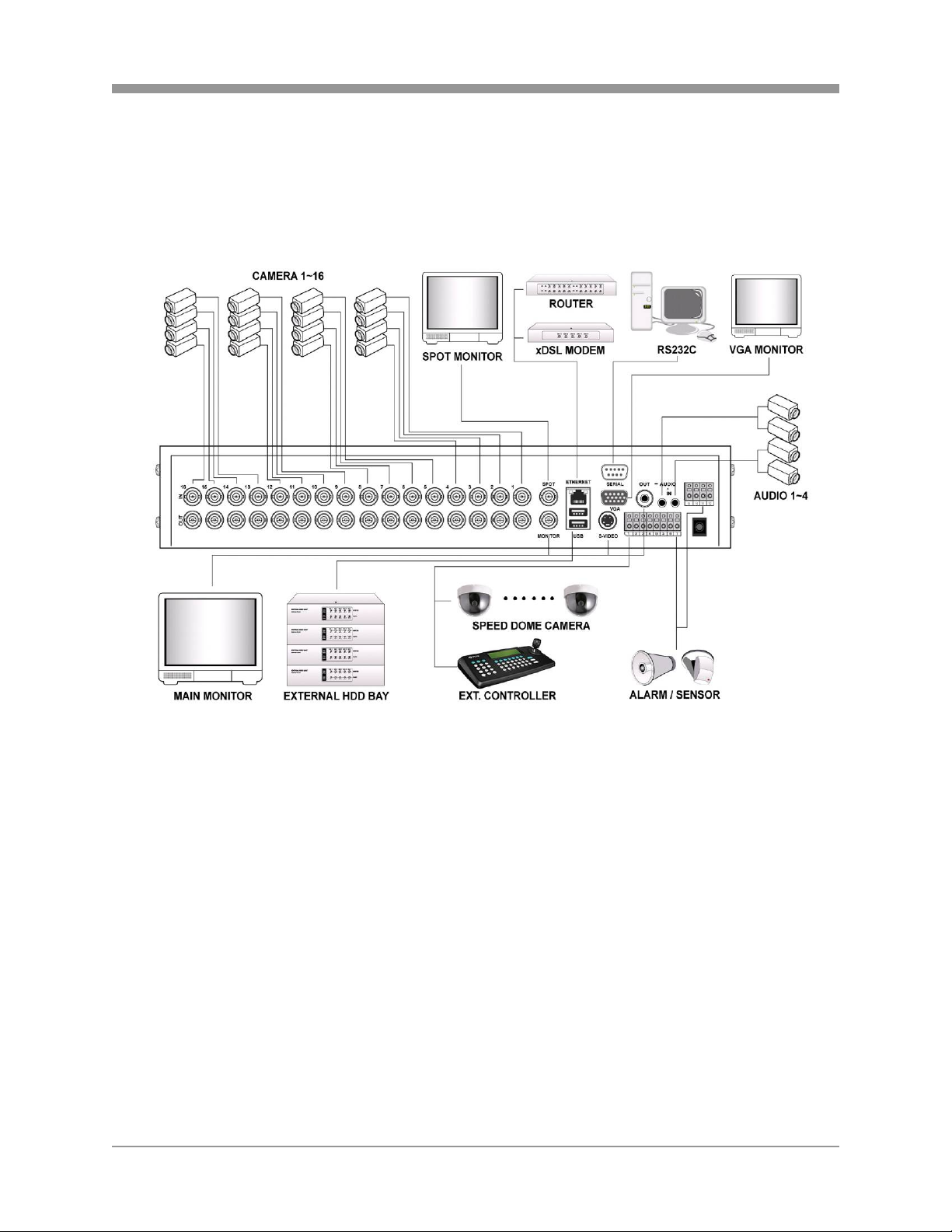
III. INSTALLATION AND CONNECTIONS
3.1 CONNECTIONS LAYOUT
SAGA “ST” Series
26
Page 28

SAGA “ST” Series
3.2 VT-XHD10U
27
Page 29
3.3 EXTERNAL TERMINAL CONNECTION
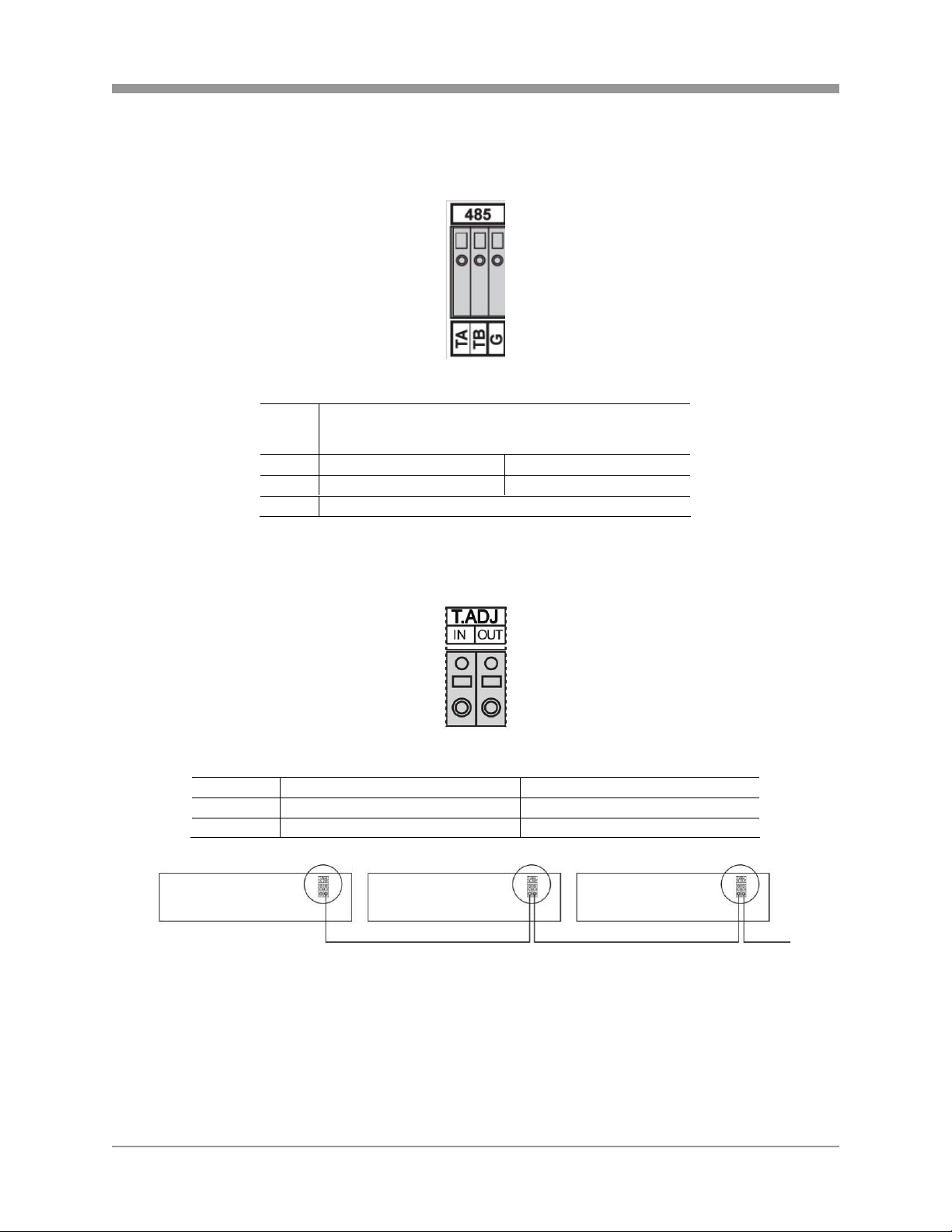
3.3.1 RS-485
3.3.2 TIME ADJUST
No DESCRIPTION
1 TA(TX+) RS485:Transmit data
2 TB(TX-) RS485: Receive data
3 GND
SAGA “ST” Series
NO DESCRIPTION FALLING EDGE
1 TIME REFERENCE INPUT TTL
2 TIME REFERENCE OUTPUT
To Other Time Adjust Terminals
28
Page 30
SAGA “ST” Series
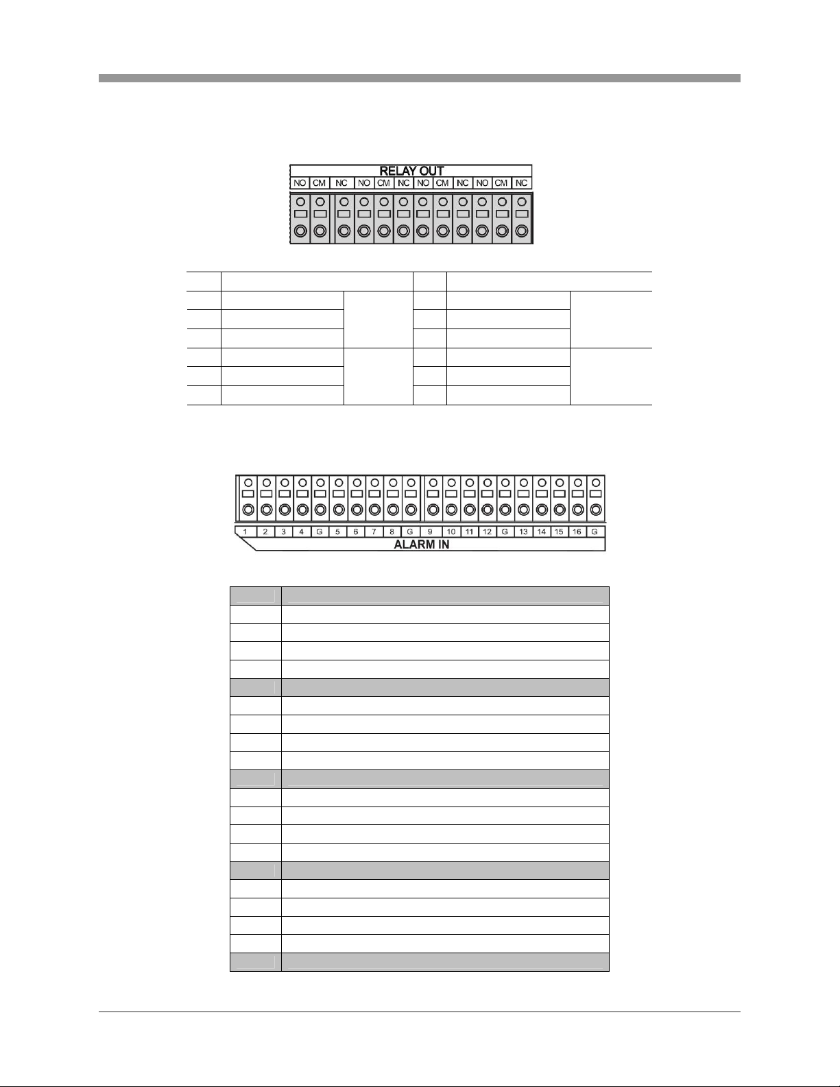
3.3.3 RELAY OUTPUT
NO DESCRIPTION NO DESCRIPTION
1 NO(Normal Open) 7 NO(Normal Open)
2 CM(Common) 8 CM(Common)
3 NC(Normal Close)
4 NO(Normal Open) 10 NO( Normal Ope n)
5 CM(Common) 11 CM(Common)
6 NC(Normal Close)
3.3.4 ALARM SENSOR INPUT
ALARM
V-LOSS
9 NC(Normal Close)
12 NC(Normal Close)
MD
POWER
USER
NOT USED
HDD ERROR
No DESCRIPTION
1 EXTERNAL ALARM 1 INPUT
2 EXTERNAL ALARM 2 INPUT
3 EXTERNAL ALARM 3 INPUT
4 EXTERNAL ALARM 4 INPUT
G ALARM IN COMMON GND
5 EXTERNAL ALARM 5 INPUT
6 EXTERNAL ALARM 6 INPUT
7 EXTERNAL ALARM 7 INPUT
8 EXTERNAL ALARM 8 INPUT
G ALARM IN COMMON GND
9 EXTERNAL ALARM 9 INPUT
10 EXTERNAL ALARM 10 INPUT
11 EXTERNAL ALARM 11 INPUT
12 EXTERNAL ALARM 12 INPUT
G ALARM IN COMMON GND
13 EXTERNAL ALARM 13 INPUT
14 EXTERNAL ALARM 14 INPUT
15 EXTERNAL ALARM 15 INPUT
16 EXTERNAL ALARM 16 INPUT
G ALARM IN COMMON GND
29
Page 31

3.3.5 VGA PIN LAYOUT
No DESCRIPTION
1 RED(Red Video [75ohm, 0.7Vp-p] )
2 GREEN(Green Video [75ohm, 0.7Vp-p] )
3 BLUE(Blue Video [75ohm, 0.7Vp-p] )
4~12 Reserved
13 HSYNC or CSYNC(Horizontal or Composite Sync.)
14 VSYNC(Vertical Sync.)
15 Reserved
3.3.6 RS-232C PIN LAYOUT
SAGA “ST” Series
No Description No Description
1 DCD Data Carrier Detect 6 DSR Data Set Ready
2 RxD Receive data 7 RTS RS232C: RX/TX data
3 TxD Transmit data 8 CTS RS232C: RX/TX data
4 DTR Data Terminal Ready 9 RI Ring Indicator
5 GND Signal Ground
30
Page 32

SAGA “ST” Series
IV. BASIC OPERATION
This section will cover basic features of the DVR, including its main screen and the
explanation of some of the alerts. It will also cover the DVR status, the view modes of
the DVR, automatic sequence, digital zoom, basic playback modes and audio playback.
4.1 MAIN SCREEN
1 2 3
4
1. REMAINING HARD DRIVE SPACE / PLAYBACK STATUS
The remaining hard drive space is displayed either in percentage or in Gigabytes. If the
hard drive overwrite is set to on, the counter will remain as 0 and the DVR will continue
to write on to the hard drive from the beginning. The counter will remain 0 as long as the
hard drive is full with previously recorded data, and will display its original size once the
hard drive is formatted. In playback mode, it displays the direction and the speed of the
playback.
2. CHANNEL STATUS
The status of each channel is displayed in color codes.
z -: non-recording
z N: continuous (manual) recording
z E: event recording
z S: schedule recording
31
Page 33

SAGA “ST” Series
3. DATE AND TIME
Current date and time is displayed when in live monitoring mode. Recorded date
and time is displayed when in playback mode.
4. CHANNEL INFORMATION
The channel information is displayed. When the channel is in normal recording
mode, it will display the channel title as entered by the user. When the channel is in
event recording mode, it will display the appropriate event recording mode: alarm,
motion and video loss.
4.2 STATUS SCREEN
The status screen displays the basic information about the DVR. Press the STATUS
button to access the information screen.
1. FIXED HDD TOTAL SPACE
Displays the total amount of installed hard drive space, including the hard drive
space in the expansion bays.
2. FIXED HDD FREE SPACE
Displays the available remaining hard drive space, including the hard drive space in
the expansion bays.
3. BACKUP HDD TOTAL SPACE
Displays the total amount of backup hard drive space, including the hard drive space
in the expansion bays. Backup hard drive total space will display zero bytes if none
of the hard drives is designated as backup hard drives.
4. BACKUP HDD FREE SPACE
Displays the available remaining backup hard drive space, including the hard drive
space in the expansion bays. Backup hard drive total space will display zero bytes if
none of the hard drives is designated as backup hard drives.
32
Page 34

SAGA “ST” Series
5. RECORD PROGRAM
Displays current recording program.
6. RECORD TYPE
Displays current event recording mode.
7. SOFTWARE VERSION
Displays current software version of the DVR.
8. HARDWARE VERSION
Displays current hardware version of the DVR.
9. DHCP (DYNAMIC HOST CONFIGURATION PROTOCOL)
Displays the status of the DHCP application.
10. IP ADDRESS
Displays currently assigned IP address.
11. SUBNET MASK
Displays currently assigned subnet mask.
12. GATEWAY
Displays currently assigned gateway.
13. DNS (DOMAIN NAME SERVER)
Displays currently assigned DNS server information.
14. PORT
Displays currently assigned network port.
15. DYNAMIC IP SERVER
Displays currently assigned backup IP server.
16. MAC ADDRESS
Displays the DVR’s MAC address (Media Access Control address).
17. USB STORAGE
Displays the size of the external hard drive space or USB Flash Memory.
18. USB CD / DVD
Displays the status of installed CD or DVD optical drive.
19. IP SERVER RESPONSE
Indicates the connectivity status with the IP server.
33
Page 35

SAGA “ST” Series
4.3 LIVE VIEW
The live view displays each channel at 30 frames per second, for the total of 120 frames
per second for VT-ST420, 240 frames per second for VT-ST820 and 480 frames per
second for VT-ST1620.
4.3.1 LIVE VIEW MODE SEQUENCE
Press the DISPLAY button to toggle between different view modes.
4.3.1.1 VT-ST1620
16 Channel Mode 13 Channel Mode 10 Channel Mode
9 Channel Mode A 9 Channel Mode B 7 Channel Mode
6 Channel Mode 4 Channel Mode A 4 Channel Mode B
4 Channel Mode D 4 Channel Mode E 4 Channel Mode C
34
Page 36

SAGA “ST” Series
4.3.1.2 VT-ST820
8 Channel Mode A 7 Channel Mode 6 Channel Mode
4 Channel Mode A 4 Channel Mode B
4 Channel Mode C
4 Channel Mode D 4 Channel Mode E
4.3.2 FULL SCREEN DISPLAY
Press the desired channel button to directly display the channel on the monitor. Press
+10 then a secondary number for any channel numbers higher than 9.
Press Numeric button 1 to display channel 1.
35
Page 37

SAGA “ST” Series
Press +10 button and then 2 button to display channel
12.
4.3.3 AUTOMATIC SEQUENCE
Press the SEQ button to activate the automatic sequence display. Please change “ADD
AUTO SINGLE” option to ON to include single channel display into the automatic
sequence. Any of the view modes can be skipped by selecting the dwell time to 0.
…
16 Channel Mode 10 Channel Mode 7 Channel Mode
…
… …
4 Channel Mode A Channel 1 Channel 16
4.4 FREEZE
The freeze function allows the user to freeze the live view mode at any given time.
There are two modes in which the freeze function is effective: single screen (full
screen) mode and multi-screen mode.
36
Page 38

SAGA “ST” Series
4.4.1 SINGLE SCREEN VIEW MODE
In single screen view mode, press the FREEZE
button to freeze the live screen.
As the screen freezes, “FREEZE” will be displayed in
the upper left corner of the screen. Press the
FREEZE button once more to unfreeze the screen.
4.4.2 MULTI SCREEN VIEW MODE
In any multi screen view mode, press the FREEZE
button and “FREEZE” will be displayed in the upper
left corner of the screen. Please note that none of the
channels will be frozen immediately.
Press the numeric buttons for the channels to be
frozen. In the example to the left, channel 2, 3, 5, 7, 8
and 15 have been frozen. Press the numeric buttons
for the channels once again to unfreeze them.
37
Page 39

SAGA “ST” Series
4.5 ZOOM
During the live view mode or during the playback mode, it is possible to zoom into a
section of the screen to get a digital close-up of up to 8 times the normal size.
Press the numeric button to select the channel to
zoom into.
Press the ZOOM button to enter the zoom mode.
The initial zoom ratio is 2X the normal size.
Use the directional buttons to move the zoom window
to the desired location.
Press the ESC button to exit out of the zoom mode.
38
Page 40
SAGA “ST” Series
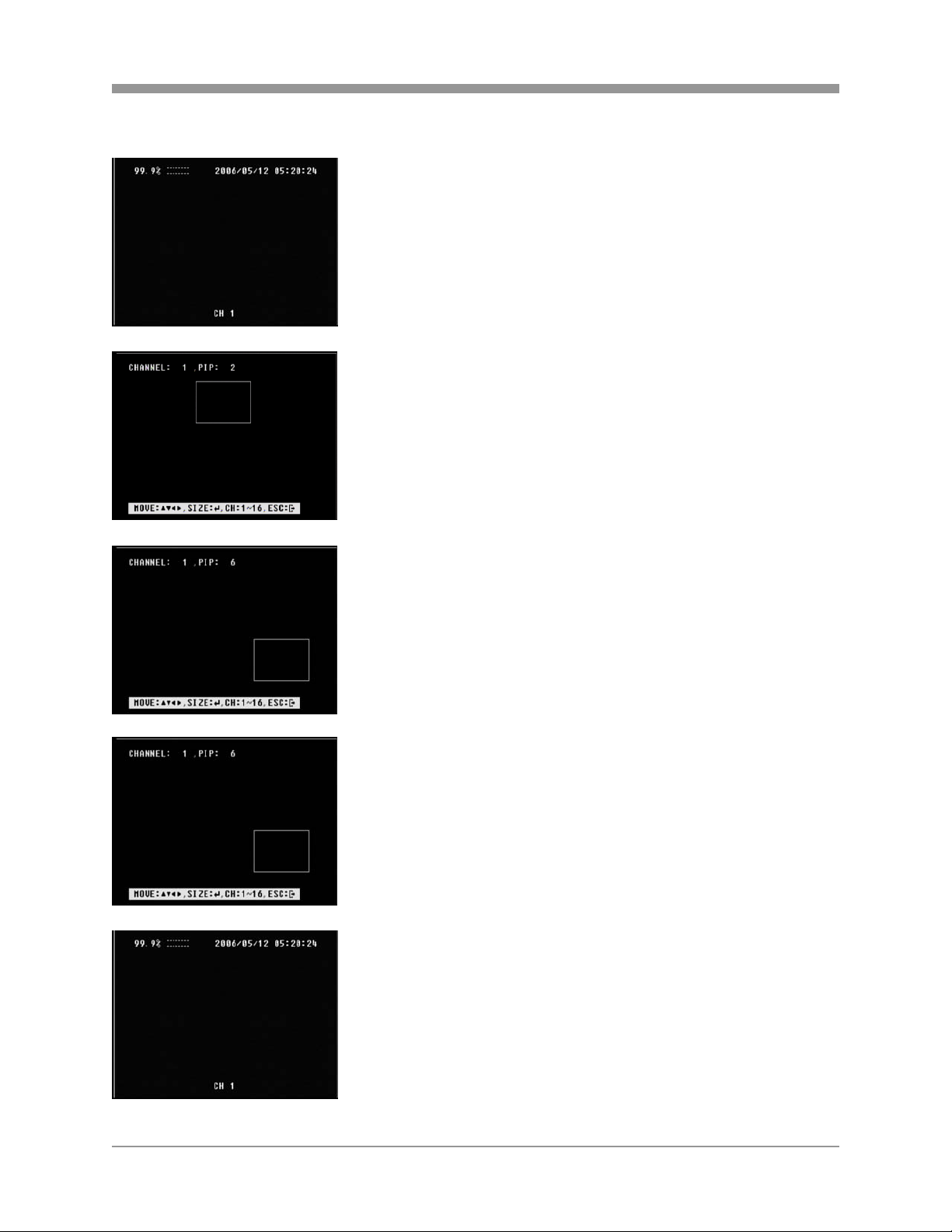
4.6 PICTURE-IN-PICTURE
Select the background channel by pressing the
desired numeric button.
Press the PIP button to activate the PIP mode.
Pressing the numeric buttons will change the PIP
window to change the channel to the desired channel.
Use the directional buttons to place the PIP window to
the desired location on the screen.
Press the ESC button to exit from the PIP mode.
39
Page 41

SAGA “ST” Series
4.7 SPOT MONITOR
The spot monitor allows viewing of individual cameras in live mode while the main
monitor may be busy with different tasks, such as playback. The ST series offers a
single channel spot output.
During any view modes, press the SPOT button for
Spot Monitor Mode.
Press any channel numbers to display the channel in
full screen mode on the spot monitor.
The spot monitor will display the channel accordingly.
Press the SPOT button to exit from the Spot Monitor
Mode.
40
Page 42

SAGA “ST” Series
4.8 BASIC RECORDING
When the REC button is pressed, the SAGA series DVR uses Program 6, which is the
default record setting:
There are total of 10 customizable record programs. Please note that QUICK SETUP
supersedes any other recording settings when activated.
The factory default record programs are as follows:
RECORD
PROGRAM
EVENT
TYPE
EVENT
OPTION
IMAGE SIZE 720X240 360X240 360X240 360X240 720X240 720X240 720X240 720X480 720X480 720X480
NORMAL
RECORD
EVENT
SINGLE
EVENT
COMPLEX
NORMAL
QUALITY
EVENT
QUALITY
PRE-ALARM 5 5 5 5 5 5 5 5 5 5
POST-
ALARM
EVENT A/L/M A/L/M A/L/M A/L/M A/L/M A/L/M A/L/M A/L/M A/L/M A/L/M
0
COMPLEX
CH
ONLY
0
-
0
FINE
FINE
10
1 2 3 4 5 6 7 8 9
SINGLE SINGLE COMPLEX SINGLE SINGLE COMPLEX SINGLE SINGLE COMPLEX
CH
ONLY
4 3 7 2 1 3 1 1 1
15 30 - 15 30 - 3 10 -
- - 7 - - 3 - - 1
LOW FINE
LOW FINE
10 10 10 10 10 10 10 10 10
CH ONLY
CH
ONLY
SUPER
FINE
SUPER
FINE
CH
ONLY
LOW
LOW
CH
ONLY
FINE
FINE
CH
ONLY
SUPER
FINE
SUPER
FINE
CH
ONLY
LOW FINE
LOW FINE
CH
ONLY
CH
ONLY
SUPER
FINE
SUPER
FINE
For a detailed explanation of each function and feature, please refer to 6.3.2 RECORD
PROGRAM under section 6.3 RECORD SETUP on page 90.
Press the REC button to start recording. The circles
representing the channel status will change color
based on the recording mode. Press the REC button
once again to stop the recording.
41
Page 43

4.9 BASIC PLAYBACK
4.9.1 PLAY / REVERSE PLAY / PAUSE / STOP
Press the PLAY / PAUSE button and the play icon will
be displayed. The DVR starts the playback from the
earliest recorded data if the playback mode is entered
for the first time.
Press the DIRECTION button to change the playback
direction.
Press the PLAY / PAUSE button during the playback
to pause the playback.
When the playback reaches the end of the recorded
data, then the playback will pause automatically.
Press the LIVE button to exit to the live view mode.
SAGA “ST” Series
42
Page 44

SAGA “ST” Series
4.9.2 FAST FORWARD / REWIND
The FAST button accelerates the speed of playback
in one direction. Each pressing of the button
accelerates the speed twice the previous speed. In
other words, from normal speed, the acceleration
increment is 2X, 4X, 8X, 16X, 32X, 64X and 128X.
Pressing the DIRECTION button will change the
direction of fast forward to rewind while maintaining
the same speed.
4.9.3 PICTURE-BY-PICTURE
Pause the playback by pressing the PLAY / PAUSE
button.
Press the FORWARD PICTURE-BY-PICTURE button
to review and to advance through the recorded data
picture-by-picture.
Press the REVERSE PICTURE-BY-PICTURE button
to play in reverse and view recorded data picture-bypicture.
43
Page 45

SAGA “ST” Series
4.9.4 SLOW
The SLOW button slows down the speed of playback
in one direction. Each pressing of the button further
slows down the speed twice the previous speed. In
other words, from normal speed, the slow down
increment is 1/2X, 1/4X, 1/8X, 1/16X, 1/32X, 1/64X
and 1/128X.
Pressing the DIRECTION button will change the
direction of slow playback to the opposite direction
while maintaining the same speed.
4.9.5 LOOP PLAYBACK
The playback can be marked in two different locations so that it can be looped
repeatedly.
During any playback mode, press the A button to
mark the beginning of the loop, POSITION A.
When the desired location is found, press the B
button to mark the end of the loop, POSITION B. The
desired location can be reached by any playback
functions such as fast forward, slow, and etc.
44
Page 46

SAGA “ST” Series
As soon as the end of the loop is marked, then the
playback returns to POSITION A.
When the end the loop is reached, the playback
returns to POSITION A and the loop playback is
repeated.
Press the CLEAR button to exit from the loop
playback mode.
4.9.6 BOOKMARK
The bookmark provides a quick and easy way to mark the desired location during
playback so that it can be easily retrieved for later playback.
During the playback, pause by pressing the PLAY /
PAUSE button when the desired location has been
reached.
Press the BOOKMARK button to mark the current
location.
45
Page 47

SAGA “ST” Series
4.9.7 AUDIO PLAYBACK
The audio is always recorded in real time regardless of the recording speed. To listen
into the desired audio channel, press the AUDIO SEL button and then channel 1
through 4.
By default, the audio will playback along with the equivalent video camera (i.e. channel
1 audio will play back along with channel 1 video).
46
Page 48

SAGA “ST” Series
V. ADVANCED OPERATION
This section will cover advanced features of the DVR such as backup (copy), pan tilt
and zoom camera controls, alarm, video loss and motion recording, and various
playback search options.
5.1 BACKUP
The DVR is capable of backing up to various media, such as DVD-RW, CD-RW, USB
Flash drives, and external hard drives. Please note that besides the optical media, the
backup devices must be USB 2.0 compliant and they can be connected to any of the
three available USB slots. Every time a backup is made, the mini player will be copied
along with the content to facilitate viewing of the backup video on any Windows based
personal computers. All backup media will include a multi-channel small viewer.
5.1.1 CD-RW / DVD-RW / DVD+RW
The SAGA Series DVR is equipped with a DVD-RW / CD-RW drive for backups. RW
media was specifically chosen because of its unique ability to be used over and over.
Data backups can be written to the same RW disk until its maximum capacity is reached.
Once capacity is reached, the disk can then be reformatted and reused over and over.
Press the COPY button to enter the COPY screen.
CD-RW and DVD-RW media must be formatted prior
to backup. Select MEDIA FORMAT and then press
the ENTER button to access Media Format submenu.
47
Page 49

SAGA “ST” Series
Select INTERNAL CD-RW/DVD by pressing the + or =
buttons.
Highlight MEDIA FORMAT, and then press the
ENTER button to begin formatting.
FORMATTING will be displayed during the process.
The process may take up to approximately 20
minutes depending on the format of the backup disk.
When the process is completed, SUCCESS will be
displayed.
Press the ESC button to return to the previous menu.
Highlight COPY and then press the ENTER button to
access the copy submenu.
48
Page 50

SAGA “ST” Series
Select the location of the file to be backed up from.
If the location is unknown, leave the HDD ID on
NORMAL.
Select the channels to be backed up. By default, all
channels are selected. To exclude a channel,
highlight a channel number and then switch them to
“--“.
The beginning and the end of the available files are
listed automatically as shown on the left.
Select the beginning time and the end time of the
period to be backed up, and then press the ENTER
button to start the backup.
When prompted, enter an eight digit numeric
password to encrypt the backup. This password will
be needed to later retrieve the data. Data encryption
can be bypassed by pressing the ESC button.
49
Page 51

5.1.2 CD-R
SAGA “ST” Series
The backup progress is displayed on the right upper
corner of the screen, and will disappear automatically
when the backup process is finished.
The backup disk can be reformatted and reused over
and over.
Insert the CD into the CD-ROM or DVD-ROM of a
computer, and the small player will load automatically
showing all available data for playback.
Highlight COPY and then press the ENTER button to
access the copy submenu.
Select INTERNAL CD-RW/DVD by pressing the + or –
button.
Select the channels to be backed up. By default, all
channels are selected. To exclude a channel,
highlight a channel number and then switch them to
“--“.
50
Page 52

SAGA “ST” Series
The beginning and the end of the available files are
listed automatically as shown on the left.
Select the beginning time and the end time of the
period to be backed up, and then press the ENTER
button to start the backup.
When prompted, enter an eight digit numeric
password to encrypt the backup. This password will
be needed to later retrieve the data. Data encryption
can be bypassed by pressing the ESC button.
The DVR will start creating a buffer for the selected
data to be backed up. The status of the buffer being
created will be displayed in the upper right corner of
the screen.
The backup progress is displayed on the right upper
corner of the screen, and will disappear automatically
when the backup process is finished.
51
Page 53

SAGA “ST” Series
Insert the CD into the CD-ROM or DVD-ROM of a
computer, and the small player will load automatically
showing all available data for playback.
5.1.3 USB FLASH MEMORY
The USB 2.0 flash memory comes in various sizes, up to 8 Gigabytes of storage per
flash memory. It is much faster in comparison to optical media when it comes to
copying necessary files. The following manufacturers’ models have been tested to be
fully compatible with the SAGA series DVRs.
z SANDISK Cruzer Mini – all capacities
z SANDISK Cruzer Micro – all capacities
z LEXAR JumpDrive Lightening – all capacities
z MEMOREX TravelDrive – all capacities
z I/O MAGIC Giga Bank – all capacities
z PNY – all capacities
As the compatibility is continuously being tested, please check with the Vitek Help Desk
before using non-listed manufacturers’ models.
Insert the flash memory into any available USB 2.0 port. The flash memory will light up
as it draws power from the DVR.
Press the COPY button to enter the COPY submenu.
Highlight COPY, then press the ENTER button to
enter the COPY screen.
Select the location of the USB flash memory. The
example to the left has selected the front USB port.
52
Page 54

SAGA “ST” Series
Select the location of the file to be backed up from.
If the location is unknown, leave the HDD ID on
NORMAL.
Select the channels to be backed up. By default, all
channels are selected. To exclude a channel,
highlight a channel number and then switch them to
“--“.
The beginning and the end of available file are listed
automatically as shown on the left.
Select the beginning time and the end time of the
period to be backed up, and then press the ENTER
button to start the backup.
When prompted, enter an eight digit numeric
password to encrypt the backup. This password will
be needed to later retrieve the data. Data encryption
can be bypassed by pressing the ESC button.
53
Page 55

SAGA “ST” Series
The backup progress is displayed on the right upper
corner of the screen, and will disappear automatically
when the backup process is finished.
The copied files are listed as “Dvr-20060503-
202016.dvr”. They can be retrieved and played back
using the client software, or the embedded program –
“FileViewer.exe”.
5.1.4 EXTERNAL HARD DISK DRIVE
Follow the same procedure as the USB flash memory in section 5.1.2.
5.1.5 COPY STATUS
During any backup process, a detailed description of the copy process can be viewed.
Copy status will display the start and end of the data to be backed up, and the current
time of the data being copied.
Press the COPY button to enter the COPY submenu.
Highlight COPY STATUS and then press the ENTER
button to see the copy status.
54
Page 56

SAGA “ST” Series
Displays the current copy status.
5.1.6 COPY STOP
The backup process can be interrupted at any time during the process.
Press the COPY button to enter the COPY submenu.
Highlight COPY and then press the ENTER button to
access the copy submenu.
Instead of the normal copy submenu, the DVR will
display an option to stop the backup process.
55
Page 57

SAGA “ST” Series
Highlight YES and then press the ENTER button to
stop the backup process.
5.2 PAN / TILT / ZOOM CAMERA CONTROL
The SAGA series DVR comes with an extensive list of compatible PTZ cameras.
Please read and follow the PTZ manufacturer’s instruction manual and understand its
settings fully prior to proceeding to attempt to connect and control the PTZ camera
through the DVR. Please refer to PTZ model selection under 6.6.5 PTZ under 6.6 LINK
SETUP on page 118.
5.2.1 BASIC PAN / TILT / ZOOM CONTROL
Select the desired channel by pressing the numeric
button for the full screen view.
Press the PTZ button to enter the PTZ camera control
mode. Use the directional buttons for the pan and tilt
movement, +/- buttons to focus in/out, or AF button
for auto focus, and the shuttle ring to zoom in and out.
The movement speed of the PTZ camera can be
changed by pressing the FUNCTION button and then
the + or – button to increase or decrease the speed.
56
Page 58

SAGA “ST” Series
5.2.2 CREATING AND MOVING TO PRESET POINTS
During the PTZ control mode, press the PRESET
button to activate the PTZ(PRESET)MOVE mode. If
there are any preset points predefined, pressing the
numeric buttons will move the PTZ camera to the
preset points. A total of 16 preset points can be
recalled.
If there are no preset points predefined, then press
the PRESET button once again to activate
PTZ(PRESET)SET mode. Move the PTZ camera to
the desired location, then press the numeric buttons
to define the numbers to the locations. A total of 16
preset points can be defined.
5.3 ADVANCED RECORDING
Advanced recording is comprised of customizing various event recording options such
as alarm, video loss and motion. Event recording maximizes recording time with the
available storage space. Event recording can also utilize the backup mode hard drives
in addition to normal recording hard drives for duplicate copies of the events. For more
information, please refer to 6.3.7 BACKUP MODE under 6.3 RECORD SETUP on page
96.
Prior to activating event recording, please verify that event options are activated in
either the QUICK SETUP menu or the RECORD PROGRAM menu. Please note that if
QUICK SETUP is not used, then certain parameters in the EVENT menu must be
activated for the event recording to work properly. Moreover, please verify that the
proper program number is being used under RECORD SETUP.
There are two methods for event recording. The first method is recording events in
addition to manual recording, and the second method is event recording only. The first
method involves leaving the REC button on to start recording manually and combining
event recording. This would be useful in a scenario where a location needs to be
recorded continuously even at a very minimal recording speed, but when an event is
triggered, the recording speed is boosted to the desired pictures per second. The
second method involves leaving the REC button off so that only events are recorded.
The following settings will assume that the second method is used for event recording.
With either method, the events will trigger the designated relays and send out
57
Page 59

SAGA “ST” Series
notification e-mails if the e-mail addresses have been defined. Please see 6.4.8 RELAY
OUTPUT under 6.4 EVENT SETUP section on page 101 and 6.6.5 E-MAIL under 6.5
LINK SETUP on page 119.
5.3.1 ALARM RECORDING
Alarm recording is a form of event recording that triggers off of the circuit lines
connected to the terminal blocks in the rear of the DVR. Typical circuits comprise of
normally closed circuits (NC) and normally open circuits (NO).
Verify that the alarm option has been selected in either QUICK SETUP or RECORD
PROGRAM.
The channels on which the alarm is triggered will
display the “ALARM” message. The REC button will
light up as the DVR starts to record and the channel
status will change to red.
The recording will include the pre and post recording
time on the channels that are recording.
5.3.2 VIDEO LOSS RECORDING
Video loss recording is a form of event recording that is triggered when a channel loses
its video input signal. Video loss recording is useful to have other channels compensate
for the loss of the video signal on a specific channel. For example, when a video loss
occurs on channel 1, then the DVR can start recording on channel 2, 3 and 4.
Moreover, the channel which loses the video signal will retain the last five seconds of
the video to retain what occurred before the video loss.
Verify that the video loss option has been selected in either QUICK SETUP or RECORD
PROGRAM.
The channel on which the video loss occurred will
display the “VLOSS” message. The REC button will
light up as the channels that are designated to record
when a specific channel has a video loss start
recording.
On the example to the left, channels 2, 3 and 4 are
designated to record when channel 1 goes out.
The recording will include the pre and post recording time on the channels that are
recording.
58
Page 60

SAGA “ST” Series
5.3.3 MOTION RECORDING
Motion recording is yet another effective form of event recording that is triggered when a
channel detects motion in its field of view.
The channels which detect motion will display the
“MOTION” message. The REC button will light up
and the channel status will change the color to red in
the channels in which the motion was detected.
The recording will include the pre and post recording
time on the channels that are recording.
5.4 ADVANCED PLAYBACK
To find and access the recorded data more efficiently, the DVR provides various search
modes: calendar search, search & copy, time search, event search, block search, file
search, bookmark search and text search.
5.4.1 CALENDAR SEARCH
Calendar search provides a quick overview of the year, month, day and hours of the day
so that the data can be accessed relatively quickly.
Press the SEARCH button to access the search
screen.
Highlight CALENDAR SEARCH and press the
ENTER button to access the CALENDAR SEARCH
screen. It will start searching for the data
automatically.
59
Page 61

SAGA “ST” Series
The dates that contain recorded data will be displayed
in clear font, whereas dates without data will be in
white.
Select the desired date and then press the ENTER
button. To change the month or the year, highlight
the month or the year and then adjust the value by
pressing the + and – buttons.
When a date is selected, the DVR will then search
again for the recorded data in a 24-hour period for the
date.
The hour blocks that contain data will be displayed in
yellow. Move the highlight to the desired hour block
and then press the ENTER button to start the
playback.
Maneuver through the playback as needed. Please
see BASIC PLAYBACK on page 42.
60
Page 62

SAGA “ST” Series
5.4.2 SEARCH & COPY
Search & copy allows a quick review of the recorded data and backup onto a medium,
and thus minimizes the need to navigate through different screens to pinpoint the exact
time and duration of the video.
Press the SEARCH button to access the search
screen.
Highlight SEARCH & COPY and then press the
ENTER button to access the SEARCH & COPY
screen.
Select which hard disk drive to retrieve the data from.
If unknown, leave the HDD ID to “NORMAL”.
Select the year, month, date, hour, minutes and
seconds of the beginning of the data to retrieve. As
the values change, the picture in the preview window
will change accordingly.
61
Page 63

SAGA “ST” Series
If any of the channels need to be viewed in full screen
mode, highlight CHANNEL and then press the + or –
button to view a specific channel.
Press the ENTER button and the playback will begin.
Maneuver through the playback as needed. Please
see BASIC PLAYBACK on page 42.
When the desired footage has been found, press ESC
to return to SEARCH & COPY screen. The SEARCH
END TIME reflects where the DVR stopped the
playback and COPY MEDIA has been highlighted
automatically for the backup medium selection.
Select the desired backup medium by pressing the +
and – button.
Highlight START COPY and then press the ENTER
button to start the backup procedure.
When prompted, enter an eight digit numeric
password to encrypt the backup. This password will
be needed to later retrieve the data. Data encryption
can be bypassed by pressing the ESC button.
62
Page 64

SAGA “ST” Series
When the password has been entered, “SAVE NEW
COPY PASSWORD” will appear. The same
message appears even if the ESC button has been
pressed.
The backup process will begin and the progress will
be displayed in the upper right hand corner of the
screen.
5.4.3 TIME SEARCH
Time search provides an overview of the recorded data from the earliest available
recording to the latest available recording.
Press the SEARCH button to access the search
screen.
Highlight TIME SEARCH and then press the ENTER
button to access the TIME SEARCH screen.
63
Page 65

SAGA “ST” Series
Select which hard disk drive to retrieve the data from.
If unknown, leave the HDD ID on “NORMAL”.
Select the year, month, date, hour, minutes and
seconds of the beginning of the data to retrieve. As
the values change, the picture in the preview window
will change accordingly.
If any of the channels need to be viewed in full screen
mode, highlight CHANNEL and then press the + or –
button to view a specific channel.
Press the ENTER button and the playback will begin.
Maneuver through the playback as needed. Please
see BASIC PLAYBACK on page 42.
5.4.4 EVENT SEARCH
Event search provides an overview of the all event related recordings so that a specific
event can be quickly pinpointed and accessed.
64
Page 66

SAGA “ST” Series
Press the SEARCH button to access the search
screen.
Highlight EVENT SEARCH and then press the
ENTER button to access the EVENT SEARCH
screen.
Select which hard disk drive to retrieve the data from.
If unknown, leave the HDD ID on “NORMAL”.
if any of the channels need to be viewed in full screen
mode, highlight CHANNEL and then press the + or –
button to view a specific channel.
Select the event type by pressing the + and – button.
65
Page 67

SAGA “ST” Series
Select the year, month, date, hour, minutes and
seconds of the end of the data to retrieve. As the
values change, the picture in the preview window will
change accordingly. If all events need to be searched
up to the present time, leave the time as is.
Press the ENTER button and the list of events will
appear in chronological order, from the most recent to
the oldest.
Select the event and then press the ENTER button to
start the playback. The example to the left is playing
back motion triggered recording.
Maneuver through the playback as needed. Please
see BASIC PLAYBACK on page 42.
5.4.5 BLOCK SEARCH
Block search has the capability to retrieve the recorded data even from hard drives that
may have failed during the operation. Block search reads the logical block addressing
(LBA) of the hard disk drives where the recorded data are associated chronologically
with the actual location of the files. In other words, even if the hard drives are damaged,
it may be possible to retrieve data from the hard disk drives.
Press the SEARCH button to access the search
screen.
66
Page 68

SAGA “ST” Series
Highlight BLOCK SEARCH and then press the
ENTER button to access the BLOCK SEARCH
screen.
Select the hard disk drive to retrieve the data from. If
unknown, leave the HDD ID on NORMAL.
Select the year, month, date, hour, minutes and
seconds of the end of the data to be retrieved.
Press the ENTER button and the list of data will
appear in chronological order, from the most recent to
the oldest. The data is associated with the logical
block address of the hard disk drives.
Select the date and time and then press the ENTER
button to start the playback.
67
Page 69

SAGA “ST” Series
Maneuver through the playback as needed. Please
see BASIC PLAYBACK on page 42.
5.4.6 FILE SEARCH
File search is capable of reading and playing back the data from the media used for
backup. Insert the CD-RW or the DVD-RW into the DVD tray or connect the USB flash
memory or the external hard disk drive into the USB port.
Press the SEARCH button to access the search
screen.
Highlight FILE SEARCH and then press the ENTER
button to access the FILE SEARCH screen.
Select which medium to retrieve the data from by
using the + or – button.
68
Page 70

SAGA “ST” Series
Press the ENTER button and the list of data will
appear in chronological order, from the oldest to the
most recent.
Select the data and then press the ENTER button to
start the playback.
Maneuver through the playback as needed. Please
see BASIC PLAYBACK on page 42.
5.4.7 BOOKMARK SEARCH
Bookmark search looks up any bookmarks that have been added by the user. Please
see 4.8.6 BOOKMARK under 4.8 BASIC PLAYBACK on page 45.
Press the SEARCH button to access the search
screen.
Highlight BOOKMARK SEARCH and then press the
ENTER button to access the BOOKMARK SEARCH
screen.
69
Page 71

SAGA “ST” Series
Press the ENTER button to search for the list of
bookmarks.
Select the bookmark, and then press the ENTER
button to start the playback.
Maneuver through the playback as needed. Please
see BASIC PLAYBACK on page 42.
5.4.8 TEXT SEARCH
Text search allows searching for Point Of Sales interface entries to bring up the specific
time related to a transaction.
Press the SEARCH button to access the search
screen.
70
Page 72

SAGA “ST” Series
Highlight TEXT SEARCH and then press the ENTER
button to access Text Search submenu.
Select the hard disk drive to retrieve the data from. If
unknown, leave the HDD ID on NORMAL.
Select the channel in which to search for the text
string.
Select the year, month, date, hour, minutes and
seconds of the end of the search time.
Highlight TEXT and then press the ENTER button to
enter the text string to search.
71
Page 73

SAGA “ST” Series
Enter the text to be searched. Leave black for a wild
card (all item) search.
Move the highlight to any location besides TEXT, and
then press the enter button to list the results.
Highlight an entry, and then press the ENTER button
to start playback.
Maneuver through the playback as needed. Please
see BASIC PLAYBACK on page 42.
5.4.9 LOG FILE SEARCH
The log file keeps a list of the important events that happened to the DVR. The log file
can be saved to a USB flash memory as a text file so that it can be viewed and archived
to a computer. The following are what the DVR keeps in its log file:
72
Page 74

SAGA “ST” Series
z Power on / off
z Power loss / DVR restart
z Changes in the menu
z DVR initialization
z HDD initialization
z Network connection / disconnection
z Record start / stop
Press the SEARCH button to access the search
screen.
Highlight LOG FILE SEARCH and then press the
ENTER button to access the LOG FILE list.
Select the year, month, date, hour, minutes and
seconds of the end of the log list to retrieve.
Press the ENTER button and the log list will be listed
in chronological order, from the most recent to the
oldest.
73
Page 75

SAGA “ST” Series
Press the ESC button and highlight SAVE LOG and
then press the ENTER button to save the log file onto
a USB flash memory. The USB flash memory must
be in the front USB port.
The log file will be saved as “DvrLog.log” file.
Double-click the left mouse button to open and view
the log file.
74
Page 76

SAGA “ST” Series
VI. DVR MENU
Press the MENU button to access the main menu of the DVR. The DVR menu consists
of the following categories:
EXIT
COPY
SEARCH
LINK SETUP
SYSTEM SETUP
EVENT SETUP
RECORD SETUP
SCREEN SETUP
QUICK SETUP
75
Page 77

6.1 QUICK SETUP
SAGA “ST” Series
Quick setup enables the user to quickly setup major recording settings of the DVR. All
changes made in quick setup are affected equally to all channels. This includes the
image size, record speed, image quality, event options, pre and post recording time and
audio record settings. Moreover, the activation of quick setup overrides any other
recording settings as the quick setup supersedes regular record setup.
6.1.1 QUICK SETUP
Quick setup enables or disables the use of the quick
setup settings. The default is OFF.
6.1.2 IMAGE SIZE
Image size determines the recording picture size.
Available sizes are:
z CIF: 360 X 240
z Half D1: 720 X 240
z D1: 720 X 480
The default size is Half D1.
76
Page 78

SAGA “ST” Series
6.1.3 RECORD FRAME
Record frame determines the overall recording speed
of the DVR. The recording speed adjusts
automatically according to the image size and divided
equally between all available channels. As an
example, the 60 available recording speed is divided
equally between 16 channels on the VT-ST1620.
The default is 60 PPS.
The following chart shows the maximum recording speed for each resolution.
Resolution CIF Half D1 D1
VT-ST420 120 60 30
Recording speed per channel 30 15 7~8*
VT-ST820 120 60 30
Recording speed per channel 15 7~8
*
3~4*
VT-1620 120 60 30
Recording speed per channel 7~8
6.1.4 EVENT
6.1.5 PRE-RECORD TIME
*
3~4
*
1~2*
Select the event to be used along with the recording.
The default is MOTION. Available options are:
z Alarm
z Video Loss
z Motion
z Alarm + Video Loss
z Alarm + Motion
z Video Loss and Motion
z All
z Off
Define the pre-event record time. Select from 0 to 5
seconds. The default is five seconds.
77
Page 79

6.1.6 POST-RECORD TIME
6.1.7 IMAGE QUALITY
6.1.8 AUDIO RECORD
6.1.9 REMOTE CONTROL ID
SAGA “ST” Series
Define the post-event recording time. Select from 0
to 60 seconds. The default is ten seconds.
Define the recording image quality. Available options
are LOW, FINE and SUPERFINE. The default is
SUPERFINE.
Select the audio recording on or off for all eight
channels. The default is OFF.
Select the identification number of the DVR. There
are a total of 16 available numbers to choose from.
The following numbers may be used:
z 11 through 14
z 21 through 24
z 31 through 34
z 41 through 44
z ALL
78
Page 80

SAGA “ST” Series
For more information regarding the REMOTE CONTROL ID, please see 6.5.6 REMOTE
CONTROLLER ID under SYSTEM menu on page 107. The default is ALL.
6.2 SCREEN SETUP
`
Screen setup defines various screen related options. Any changes affect the main
video as well as the spot monitor output of the DVR.
6.2.1 AUTO SEQUENCE
Highlight AUTO SEQUENCE and then press the
ENTER button to access four pages of the auto
sequence submenu. Navigate between the pages
using the left or right directional buttons.
Define the display duration from 0 to 60 seconds. 0
seconds disables the specific display mode’s
inclusion in the sequence. The default is 3.
The first page lists the sequence display duration for
the quad display mode A through E, six channel
display mode and seven channel display mode.
79
Page 81

SAGA “ST” Series
The second page lists the sequence display duration
for the nine channel display mode A and B, ten
channel display mode, 13 channel display mode, 16
channel display mode, and the option to include single
channels.
Select the inclusion of single channels in the
automatic sequence. The default is off.
The third page lists the sequence display duration for
channels 1 through 8.
The fourth page lists the sequence display duration for
channels 9 through 16 and the option to skip the
channels with video loss.
Select skipping the channels without video input on or
off. The default is on.
80
Page 82

SAGA “ST” Series
6.2.2 DISPLAY
Highlight DISPLAY and then press the ENTER button
to access the display submenu.
Select the display option for the remaining space on
the hard disk drive. The default is on.
Select the display mode for the remaining free space
on the hard disk drive. The default is in percentage.
Select the display option for the recording status. The
default is on.
Select the display option for the date and the time.
The default is on.
81
Page 83

SAGA “ST” Series
Select the date format. The default is DD/MM/YY.
Select the display option for the channel title. The
default is on.
Select the display mode for the channel title. The
default is in text mode.
The bitmap mode title can only be edited using the
client software.
Select the border color that divides the channels. The
default is white.
Select the display option for the remote controller ID.
The default is OFF.
82
Page 84

SAGA “ST” Series
6.2.3 TITLE
Highlight TITLE and then press the ENTER button to
access the title submenu.
Press the enter button to edit the channel title.
Navigate through the characters by using the
directional buttons, and advance through the
characters using the + or – buttons. Press the
ENTER button to select the characters.
Up to eight characters can be entered for the channel
title.
6.2.4 MULTI-SCREEN
Several multi-screen viewing modes can be customized using any combination of
cameras. These viewing modes can be disabled and excluded from the view mode
sequence. Customizable multi-screens include: MULTI 4E, MULTI 6, MULTI 7, MULTI
9B MULTI 10, AND MULTI 13.
Highlight MULTI-SCREEN and the press the ENTER
button to access the multi-screen submenu.
83
Page 85

6.2.5 COVERT
SAGA “ST” Series
Select a view mode to customize.
The view mode can be disabled to be removed from
the sequence of view modes. The default is on.
Highlight the channel to customize, and then press
the + or – button to select the desired channel.
Highlight COVERT and then press the ENTER button
to access the covert channel submenu.
The first page lists the covert mode options for
channels 1 through 8. Highlight the desired channel
and press the + or – button to activate the covert
mode.
The default is off for all channels.
84
Page 86

SAGA “ST” Series
6.2.6 SPOT
The second page lists the covert mode options for
channels 9 through 16. Highlight the desired channel
and press the + or – button to activate the covert
mode.
Select the covert mode application. By default, the
live view, playback and network are affected by the
covert mode. Available options are:
z LIVE ONLY
z PLAYBACK ONLY
z NETWORK ONLY
z LIVE AND PLAYBACK
z LIVE AND NETWORK
z PLAYBACK AND NETWORK
z ALL
Select the display of covert on or off.
If activated, then the covert channel will display
COVERT.
Highlight SPOT and then press the ENTER button to
access the spot monitor submenu.
85
Page 87

6.2.7 CAMERA
SAGA “ST” Series
Select the spot monitor display mode:
z Manual
z Event
z Sequenced
The default is manual.
Define the spot monitor sequence mode time from 1
to 60 seconds. The default is 3 seconds.
The channels without video signals can be skipped.
Select on or off. The default is on.
Highlight CAMERA and then press the ENTER button
to access camera adjustment submenu.
Select the channel which needs to be adjusted.
86
Page 88

SAGA “ST” Series
Adjust the brightness. The default is 50%.
Adjust the contrast. The default is 50%.
Adjust the hue. The default is 50%.
Adjust the saturation of the color. The default is 50%.
87
Page 89

6.3 RECORD
SAGA “ST” Series
Record setup defines various recording options such as record schedule, record
programs, recording time estimate, audio recording, repeat recording, play modes,
backup mode and holiday recording schedules.
6.3.1 RECORD SETUP
There are 10 customizable Record Programs arranged in hourly blocks that can be
individually scheduled and adjusted. Scheduling allows the DVR to record at specific
times even when the REC button is not on.
Highlight RECORD SETUP and press the ENTER
button to access the record setup submenu.
88
Page 90

SAGA “ST” Series
1 2 3 4
1. All
Select the program for the whole day by changing the value in this section.
2. Current hour block
Highlights the current program for the current time.
3. Schedule recording
Displays the hour blocks with schedule recording. Schedule recording forces the DVR
to record even when the REC button is off.
4. Daily overview
Displays the recording program for each hour block of the day. Each hour block can be
programmed with different recording programs.
Any of the hour blocks, including “all” block can be
further customized by highlighting and pressing the
ENTER button.
89
Page 91

6.3.2 RECORD PROGRAM
1 2
SAGA “ST” Series
Any of the record settings can be customized once in
the record program mode. Any changes made will be
effective only to the hour block.
Highlight RECORD PROGRAM and then press the
ENTER button to access the record program
submenu.
3
4567
8
1. RECORD PROGRAM
There are 10 available record programs, from program 0 through program 9, where
program 0 reflects the QUICK SETUP settings. Each program can be customized
and executed from RECORD SETUP. Please see 4.7 BASIC RECORDING under
IV. BASIC OPERATION section on page 40 for the default settings for each program.
90
Page 92

SAGA “ST” Series
2. EVENT RECORD SETTING
The DVR offers two distinctive methods for recording events: SINGLE mode versus
COMPLEX mode. Furthermore, both modes offer EVENT CHANNEL only and ALL
CHANNELS mode for a total of four possible event recording options.
A. Single Mode
Single Mode event recording allows recording a specific channel at up to 30 pictures
per second regardless of the image size. When the need arises to record at a
higher rate for a specific channel and not be confined to the total available record
rate, SINGLE mode allows allocating recording rates to specific channels beyond
what would normally be available. The ST series offer a maximum of 120 PPS in CIF
resolution, but utilizing Single Mode will allow the DVR to be configured up to 480
PPS.
Please note, however, that the maximum allowed in Single Mode is limited to the
sum of normal recording and event recording.
1) Event Channel Only
The event channel records at a predetermined recording speed.
2) All Channels
The event channel records at a predetermined recording speed and triggers the rest
of the channels to record with the remaining record rate, divided equally amongst the
non-event channel.
Please refer to the following sample scenarios for a better understanding of the
SINGLE MODE event recording.
- SCENARIO 1 – Event Channel Only Mode at D1 resolution
The owner of a gas station wants to set up the DVR to record at maximum rate on
D1 resolution on channels that detect motion. At the same time, the owner would
like to record continuously at one picture per second.
Normal record is set to 1 PPS, and the remaining
available record rate of 15 PPS is allocated for
each channel for all 16 channels.
CH-SUM indicates the total of the record rate of
the channel that would start recording at 15 PPS
plus the sum of the record rate of the remaining
channels 15 PPS, hence the total of 30 PPS, the
maximum allowed record rate for D1 resolution.
91
Page 93

SAGA “ST” Series
When the REC button is on, this setup continuously takes one picture per second
until a movement is detected, where the record rate will jump to 15 PPS for the
channel that triggered the event.
Please note that the total of the Single Mode event recording rate of 240 PPS
exceeds the maximum D1 resolution record rate of 30 PPS, but in reality, a total of
30 PPS is used per group at any given moment.
- SCENARIO 2 – Event Channel Only Mode at Half D1 resolution
A convenient store owner wants to record only when there’s an event at Half D1
resolution at 30 PPS only on the channels that trigger alarm events.
Normal record rate is set to 2 PPS per channel,
thus allowing the event record to be at 30 PPS.
CH-SUM indicates the total of the record rate of
the channel that would start recording at 30 PPS
plus the sum of the record rate of remaining
channels of 30 PPS, hence the total of 60 PPS,
the maximum allowed record rate for the Half D1
resolution.
The changes in Normal Record’s PPS will affect the PPS transmitted over the
network for the ST series. The setup in this sample scenario will transmit 2 PPS
over the network.
The total of the Single Mode event record rate of 480 PPS exceeds the maximum
Half D1 resolution record rate of 60 PPS, but in reality, a total of 60 PPS is used at
any given moment.
-SCENARIO 3 – All Channels Mode at D1 resolution
The gas station owner from scenario 1 now wants to record all channels even if one
channel is triggered to record. He still wants the triggered channel to record as
close to real time as possible, and the rest of the channels to record with the
remaining available record rate.
Normal record rate is irrelevant in the calculation
of the total record rate as long as it does not
exceed 30 PPS, the maximum allowed for Half D1
resolution. The event PPS is calculated
automatically after subtracting PPS for the
channel that records on event.
92
Page 94

SAGA “ST” Series
The illustration shows that at any given time, a channel would record at 30 PPS
when an alarm circuit is triggered, whereas the rest of the channels will record at 2
PPS ( (60 – 30) / 15 = 1 PPS). For example, if channel 3 is triggered to start
recording at 30 PPS, channels 1, 2 and 4 through 16 start recording at 2 PPS.
B. Complex Mode
Complex Mode event recording records exactly at the predetermined record rate for
all channels. The total record rate must be confined within the maximum record rate
allowed for the resolution.
1) Event Channel Only
The event channel records at a predetermined recording speed.
2) All Channels
The event channel records at a predetermined recording speed and triggers the rest
of the channels to record with the remaining record rate, divided equally amongst the
non-event channel.
3. NORMAL RECORD RATE
Define the manual recording rate. The maximum recording rate per resolution is CIF
at 120 pps, Half D1 at 60 pps and D1 at 30 pps. At any image size, the DVR can
record at the recording rate of 30 pps total per record group, for the maximum global
record rate of 120 pps. Please note that the channels are paired at CIF resolution,
thus all odd channel settings will reflect on all even channels.
4. EVENT RECORD RATE
Event Record Rate configures the recording speed for each channel when for event
recording. When an event is triggered, each channel, or all channels will record as
defined. Please see 2. EVENT RECORD SETTING on page 91.
5. RECORD QUALITY
Select the record quality for normal recording and event recording. Available options
are Low, Fine and Superfine.
6. PRE / POST EVENT RECORD TIME
Select the pre and post event record time. 0 to 5 seconds for pre record time and 0
to 60 for post record time.
7. EVENT OPTION
Select event option for each channel. 0 for on and – for off.
8. IMAGE SIZE
The DVR is capable of recording in three different resolutions: CIF (360 x 240), Half
D1 (720 x 240) and D1 (720 x 480).
93
Page 95

SAGA “ST” Series
6.3.3 IMAGE QUALITY
Image quality predicts how much time the DVR will record based on the record settings.
Highlight IMAGE QUALITY and then press the
ENTER button to access the image quality screen.
Select the image quality by pressing the + or – button.
The FILE SIZE, RECORD TIME and TOTAL TIME
will adjust automatically based on the picture quality
and the content of the camera.
Please verify that the REC button is off.
6.3.4 AUDIO RECORD
Highlight AUDIO RECORD and then press the
ENTER button to access the audio record submenu.
Enable or disable the audio recording option for
channels 1 through 4.
The default is off.
94
Page 96

SAGA “ST” Series
6.3.5 REPEAT RECORD
Highlight REPEAT RECORD and then press the
ENTER button to access the audio record submenu.
Select the repeat recording option on or off.
The default is on.
Select the threshold at which the alarm will sound.
Select from 5% to 10%, or off.
The default is 5%.
6.3.6 PLAY MODE
Select the playback mode for the recorded data.
Available options are:
z FRAME: for higher frame rate
z FIELD: for lower frame rate
As the general rule of thumb, FRAME mode is
recommended for playing back recording rates of 10
pictures per second or higher, and FIELD mode is
recommended for recording rates of 10 pictures per second or lower. FRAME mode
greatly improves the playback quality of fast moving objects, such as PTZ cameras, or
cars passing by, whereas FIELD mode greatly improves the playback picture quality
even at one picture per second. The default is FRAME.
95
Page 97

6.3.7 BACKUP MODE
6.3.8 HOLIDAY
SAGA “ST” Series
Select the recording mode for the backup hard disk
drives. Available options are:
z MIRROR: create a real-time duplicate copy
of the normal recording hard disk drives.
z EVENT: create a backup hard disk drive of
event recordings only.
The default is off.
Highlight HOLIDAY and then press the ENTER button
to access the holiday schedule screen.
Select the holiday recording option on or off.
The default is off.
Define the holidays in MM/DD format. Adjust the
values using the + or – buttons.
96
Page 98

SAGA “ST” Series
6.4 EVENT
Event setup defines various event options such as the motion grid and the motion
detection sensitivity, the main screen event response option, buzzer option, sensor
input and relay output options.
6.4.1 MOTION DETECTION
Highlight MOTION DETECTION and then press the
ENTER button to access the motion detection
submenu.
Select the channel to customize motion related
options by pressing the + or – buttons.
97
Page 99

SAGA “ST” Series
Adjust the sensitivity of the motion detection from 1 to
5 by pressing the + or – buttons.
The default is 5.
Highlight AREA SETUP and then press the ENTER
button to access the motion grid setup screen.
Move the grey cursor around using the directional
buttons, and then press the ENTER button to disable
each grid. Press the ESC button to return to motion
menu.
z No tint: motion detection on
z Green tint: motion detection off
The default is on for all grids.
Highlight TEST MOTION and then press the ENTER
button to access motion testing screen.
Any grid that detects motion will flash a purple tint for
the period of time that it detects motion.
98
Page 100

SAGA “ST” Series
6.4.2 EVENT SCREEN MODE
Define how the main video output reacts when an
event occurs.
z EVENT F RTN: when an event occurs, the view mode is changed to that of
the channel with the event, and then returns to the previous view mode.
z EVENT M RTN: when an event occurs, the view mode is changed to multi-
channel view mode, and then returns to the previous view mode.
The default mode is SCREEN HOLD.
6.4.3 EVENT CHECK
Select the EVENT CHECK option on or off. If the
event check is set to off, then none of the event
recording options will trigger.
The default is on.
6.4.4 EVENT MESSAGE
Select the EVENT MESSAGE display option on or off.
The default is on.
z SCREEN HOLD: maintains the current
view mode.
z EVENT FULL: the channel in which the
event occurs is displayed in full screen.
z EVENT MULTI: regardless of which
channel the event occurs in, the view mode
is changed into multiple channel view mode.
99
 Loading...