

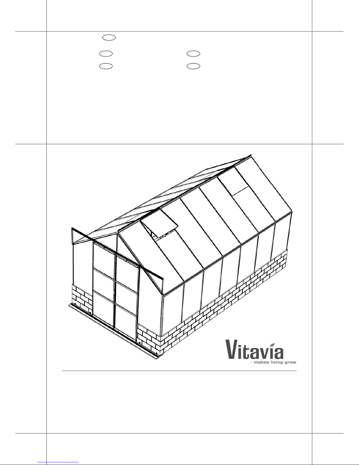
Vitavia Cassiopeia 9900, Cassandra 11500, Cassandra 9900, Cassiopeia 11500 Assembly Instructions Manual
Page 1
Assembly instructions
EN
CASSANDRA / CASSIOPEIA
9900, 11500
DA
SV
Montagevejledning
Monteringsanvisning
DE
NL
Montageanleitung
Montage Instructies
063.01.1504
Page 2
2
063.01.1504
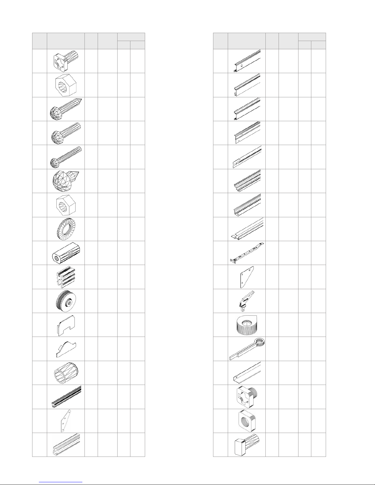
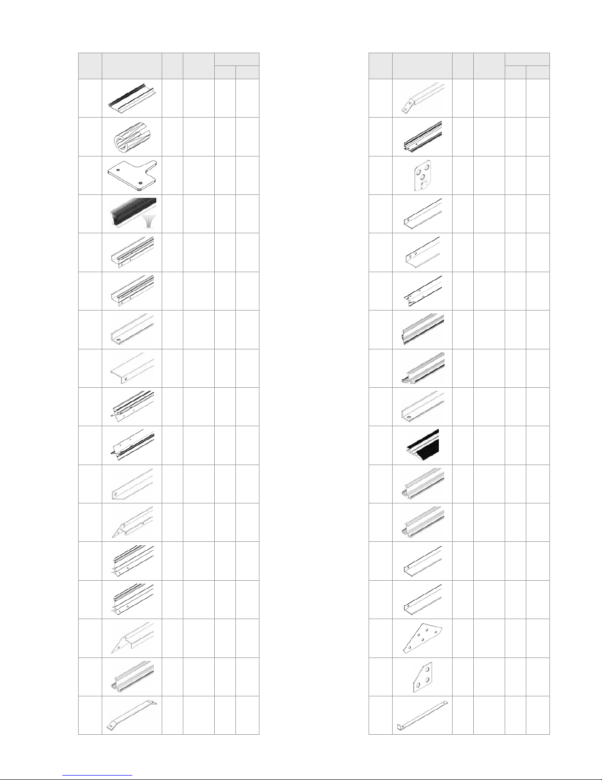
Item
No.
Part
Sect.
Ref.
Size
mm
Quantity per
9900 11500
1001
1 - 6 M6 x 12 255x 273x
1002
1 - 6 M6 258x 276x
1003
5 3.5 x 16 32x 32x
1004
5 M4 x 16 4x 4x
1005
4A M6 x 40 2x 2x
1006
6 3.5 x 6 24x 24x
1007
5 M4 4x 4x
1009
5 Ø8/4 4x 4x
1010
4A 32 2x 2x
1014
5 20 4x 4x
1015
5 Ø22 4x 4x
1017
4B 46 4x 4x
1018
4B 43.7 8x 8x
1019
6 15 4x 4x
1020
7
115000
1250001x--1x
1043
2
3
170 4x 4x
1047
3 1257 2x 2x
Item
No.
Part
Sect.
Ref.
Size
mm
Quantity per
9900 11500
1059
5 621 2x 2x
1060
5 621 2x 2x
1061
5 621 4x 4x
1062
5 613 2x 2x
1063
6 635 4x 4x
1064
6 602 4x 4x
1065
6 520 8x 8x
1066
6 602 4x 4x
1067
6 295 4x 4x
1092
1
4A
120 12x 12x
1111
5 37.5 2x 2x
1112
5 7.4 2x 2x
1113
5 25 2x 2x
1326
1 3728 2x -
1500
5 M6 x 5 2x 2x
1515
5 M6 2x 2x
2001
5L M6 x 12 1x 1x
Page 3
3
063.01.1504
Item
No.
Part
Sect.
Ref.
Size
mm
Quantity per
9900 11500
2005
5R 100 1x 1x
2006
5R 10 2x 2x
2016
6 40 8x 8x
2021
5 1923 2x 2x
2029
1 3728 2x -
2030
1 4350 - 2x
2033
4B 1898 4x 4x
2035
2 2476 1x 1x
2039
2
3
1535 2x 2x
2040
2
3
1535 2x 2x
2043
4A 416 2x 2x
2048
3 1318 1x 1x
2052
4A 3728 1x -
2053
4A 4350 - 1x
2054
2 1318 1x 1x
2055
4B 1511 10x 12x
2056
1 255 10x 12x
Item
No.
Part
Sect.
Ref.
Size
mm
Quantity per
9900 11500
2057
4B 1184 5x 6x
2058
5 1923 2x 2x
2059
4B 30 4x 4x
2060
3 633 1x 1x
2061
3 633 1x 1x
2066
2
3
1023 4x 4x
2067
2
3
1475 2x 2x
2068
2
3
1475 2x 2x
2069
1
231137 8x 8x
2070
4B 2544 1x 1x
2071
2 1475 1x 1x
2072
1 1023 10x 12x
2073
2 2484 1x 1x
2074
1 4350 - 2x
2091
2
3
175 2x 2x
2092
1
2
3
37 8x 8x
2094
3 426 1x 1x
Page 4
4
063.01.1504
Item
No.
Part
Sect.
Ref.
Size
mm
Quantity per
9900 11500
2096
3 619 2x 2x
2098
5R 1923 1x 1x
2099
5L 1923 1x 1x
2100
2
3
425 2x 2x
5001
3 33 1x 1x
5002
3 33 1x 1x
6060
4A Ø12/6 2x 2x
9104
4B 19 19x 21x
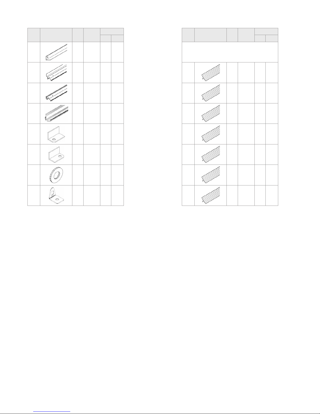
Item
No.
Part
Sect.
Ref.
Size
mm
Quantity per
9900 11500
* Included with Glazing
6602
7 1509 16x 20x
6603
7 970 8x 8x
6605
7 610 8x 8x
6606
7 540 4x 4x
6607
7 425 4x 4x
6612
7 1021 28x 32x
6613
7 1472 8x 8x
Page 5

5
063.01.1504
Page 6

6
SICHERHEITSVORKEHRUNGEN
SITE SELECTION
Always try to select a sunny location, sheltered
from the wind as much as possible.
IMPORTANT
Before assembling your new greenhouse,
please check that all parts in the provided list
are included. Please take each bundle out of
the packaging in order to identify the parts
better.
It is important that the opened bundles do not
get mixed with one another.
If something is missing please contact your
retailer.
Nuts (1002) - Max. tightening torque 3Nm.
NECESSARY TOOLS
Screw drivers (Normal and Crosshead PH2),
10 mm socket spanner or wrench, 10 mm
combination spanner, knife, measuring stick,
spirit level, Accu-drill with adjustable torque.
MAINTENANCE
The greenhouse should be thoroughly washed
with a gentle detergent occasionally. Please
check that the detergent used does not react
aggressively with aluminium or the glass xing
clips.
Ensure that the upper and lower door tracks
are cleaned regularly to avoid a build up of
debris.
0A. BASE
Important! The base must be exactly square
and level.
Foundations must extend down below the frost
level.
The front must allow room on the foundation,
minimum 70mm, for the support of the door
guide (2070) in section 4B.
Diagrams in a single frame show the view
from inside the greenhouse. Those enclosed in a double frame show the view from
outside the greenhouse.
0B. WALL
Build a wall 500mm high on the prepared foundation as shown, with an opening of 1218mm
in the front.
The front must allow room on the foundation,
minimum 70mm, for the support of the door
guide (2070) in section 4B.
Important! The wall must be exactly square
and level.
(Attention! Only when the greenhouse has to
be located in a very windy and unprotected
location: Drill through the proles at the base
of the greenhouse and connect them to the top
of the wall. Screws and wall plugs are not included.)
1. SIDE ELEMENTS
Lay all of the parts on the oor and connect
them loosely.
At this stage it is necessary with each vertical
aluminium bar (2072) to include an extra
connecting bolt, to connect corner braces
(2056) (1.4).
Loosely connect the corner plate (1092) (1.1).
In step 4 the corner plate bolts must also be
connected to the Gable ends.
2. PLAIN GABLE END
Lay all of the parts on the oor and connect
them loosely.
Include one extra connecting bolt in the
vertical bars (2067,2068 and 2071) to connect
the cross braces (2.2).
3. DOOR GABLE END
Lay all of the parts on the oor and connect
them loosely.
The door runner bars (1047) will be connected
to the horizontal bar (2048). Connect each of
these loosely from the outside with three bolts
and two nuts.
Connect (5001) and (5002) as shown in (3.9)
(3.10) with a nut.
As in step 2, please include one extra bolt in
both vertical bars (2067) and (2068) (3.3).
4A. CONNECTING THE SEPARATE
ELEMENTS
Bolt the side elements to the end elements.
(4.1) & (4.2).
Loosely connect the corner plate (1092) above
the eaves (4.3).
Assemble the ridge bar and then the corner
plates (1092) on the Gable ends (4.4/4.5).
Connect the door runner supports (2043) to
the door runner bars (1047) using washer
(6060) (4.1) and to the Gable end using bolt
(1005) and spacer (1010) (4.3) (4.6).
4B. CONNECTING THE SEPARATE
ELEMENTS
Lift the assembled structure onto the prepared
wall and connect loosely using clips (9104)
(4.9). Screws and wall plugs are not included.
Loosely connect the door runner bar (2070) to
the front of the wall (4.7) (4.8) using the 4 holders (2059) and countersunk screws (not included).
Connect the roof glazing bars (2055) between
the eaves (4.10) and the ridge bar (4.11). Insert extra bolts into each glazing bar depending on which house you have bought. The
number is indicated in a circle on each bar and
to be read beginning from both ends.
063.01.1504
1. PLEASE READ THESE INSTRUCTIONS CAREFULLY AND COMPLETELY BEFORE ASSEMBLING YOUR GREENHOUSE.
2. Sharp edges and corners can cause injury. Always wear protective glasses, gloves, shoes and headgear when handling the aluminium proles, glass and
polycarbonate sheets. Broken glass is a safety hazard – always clear up immediately and dispose of with care.
3. The product you have purchased is intended only for growing plants and should only be used for this purpose. When used for other purposes we will take
no responsibility.
4. It is recommended that this greenhouse is assembled by two people.
5. Should you encounter difculties constructing this house, or in tting the glass or polycarbonate sheets, please contact your retailer
– do not use force!
6. The greenhouse must always be anchored.
Assembly Instructions
Safety Warning
EN
Page 7

7
The corner braces (2056) (4.10), the roof
braces (2057) (4.12) and the cross braces
(2033) (4.14) (4.15) (4.16) can now be connected.
Adjust the greenhouse until it is completely
square and tighten all bolts.
Please do not over tighten. (max. 3Nm)
Press the end protectors (1017) and (1018)
onto the prole ends (4.13).
5R. and 5L. DOOR
Attention: Do not stand the assembled door
on the door gliders (1014) to avoid damaging
them.”
Push the door gliders (1014) onto both ends of
door bar (1060) (5.1).
Assemble the door as shown in diagram 5.
Connect door rollers (1015) to the door bar
(1062) using bolt (1004), washer (1009) and
nut (1007) (5.4).
Bolt door bar (1062) to upper bar (1059) (5.3)
and slide the door seal (2021) into the outside
side bar (2058) (5.5). Slide bolts (1500) into
the bottom of the bolt channel holding brush
seals (2021) and x it in place using nut (1515)
(5.6). Please ensure that for the inside side
bar, the part (2098) is used on the right in (5R)
and (2099) on the left in (5L). Connect the
door xer (1111), (1112) and (1113) as shown.
Insert bolt (2001) where both parts (1047) join
as shown.
Loosen the door supports (2043).
Now slide the door rollers into the door runner
bar (1047) (5.7). Please ensure that the door
gliders are also running on the bottom track
(2070) (5.8).
Reconnect door supports (2043).
Adjust the door so that it moves freely.
6. ROOF VENTS
Connect the side bars (1065) and the top bar
(1064) depending on the pane thickness.
Up to 4 mm, see (6.1). For 4 mm and over,
see (6.2).
Place the bolts to connect the bottom bar
(1066) in the prepared holes, and then slide
the glass into the tracks in side bars (1065)
(6.3).
Now connect bottom bar (1066), and ensure
that the window is totally square before tightening all bolts.
Position the window in the ridge bar from one
end (6.4) and (6.5) and slide it to the required
position (6.6).
Connect the window sill (1063) with the extra
bolts in the roof bars (6.7).
Connect the window opener (1067) to the bottom bar (1066) using screws (1006) (6.8).
Place the plastic cap (1019) over the end of
the window opener (6.6) and connect both
window xers (2016) onto the window sill
(1063) using screws (1006) (6.8).
7. GLAZING – CLEAR GLASS
Please note the already mentioned safety
precautions.
Press the glazing seals (1020) onto the alumi-
nium proles (7.1) and cut to length.
Begin on the roof by positioning the glass in
place and xing it by pushing the glazing list
into position at the side (7.1). Cut each list to
the length of the glass pane.
Continue to x the glass panes into the sides
and doors cutting the glazing list to match the
glass pane.
FINISHING
If desired, it is possible to seal the greenhouse
at the edges using neutral silicone. Silicone is
not in cluded.
Place the warning label inside the house.
A full range of accessories is available to help
you make the most of this product. Please
contact your local stockist for details.
SAFETY NOTICE
In the event of high winds, close all doors and
vents.
In the event of heavy snowfall, clear the roof
of the building or take suitable measures to
support the roof. Heat the building in winter.
COMMENTS
For the complete protection of your new
greenhouse, we advise you to include it in
your house insurance. Please take note of
possible building rules relating to the positioning of greenhouses.
Please stick the greenhouse model label provided onto the door bar (1062) after successfully assembling this product. This information
is important in the event that replacement
parts are later required.
Please keep these Assembly Instructions in
a safe place, for future reference!
Our policy is one of continuous improvement
and we reserve the right to change the specications without prior notice.
063.01.1504
Page 8

8
063.01.1504
STANDORTWAHL
Suchen Sie den sonnigsten, aber gleichzeitig
einen windgeschützten Platz aus.
WICHTIG
Bevor Sie mit der Montage Ihres Gewächs-
hauses beginnen, überprüfen Sie, ob alle in
der Liste aufgeführten Teile vorhanden sind.
Nehmen Sie die einzelnen Bündel aus der
Verpackung, um sie besser identizieren zu
können.
Es ist wichtig, dass die geöffneten Bündel
nicht durcheinander geraten.
„Leerschraube“ = Schraube und Mutter für die
spätere Befestigung von Teilen, vorerst ohne
sichtbare Funktion.
Fehlt etwas, dann setzen Sie sich bitte mit
Ihrem Lieferanten in Verbindung.
Muttern (1002) mit max. 3Nm anziehen.
BENÖTIGTE WERKZEUGE
Schraubendreher (Schlitz und Kreuzschlitz
PH2), 1 Schraubenschlüssel 10 mm, RingGabelschlüssel, Messer, Zollstock, Wasserwaage, Akku-Schrauber mit einstellbarem
Drehmoment.
WARTUNG
Das Gewächshaus sollte hin und wieder
gründlich mit einer neutralen Waschmittellauge
abgewaschen werden. Das Glas kann mit
einem Reinigungsmittel gesäubert werden,
das weder Kunststoffteile, den Aluminiumrahmen, noch die Glasfederklammern angreift.
Reinigen Sie regelmäßig die Türlaufschiene.
0A. FUNDAMENT
Wichtig! Das Fundament muss absolut recht-
winklig und eben sein.
An der Vorderseite müssen mindestens 70
mm für die Türlaufschiene (2070) frei bleiben
(Schritt 4B).
Das Fundament muss frostfrei gegründet werden.
Alle Zeichnungen sind von der Innenseite
des Hauses gesehen abgebildet, mit Ausnahme der Abbildungen, die in einem Doppelrahmen dargestellt sind. Diese beschreiben die Außenansicht.
0B. MAUER
Bauen Sie eine 500 mm hohe Mauer auf der
vorbereiteten Fläche und lassen Sie vorne
eine Aussparung von 1218 mm. An der Vorderseite müssen mindestens 70 mm für die
Türlaufschiene (2070) frei bleiben (Schritt 4B).
Wichtig! Die Wand muss absolut rechtwinklig
und eben sein.
(Achtung! Nur wenn das Gewächshaus an
einer sehr ungeschützten und windigen Stelle
aufgebaut werden muss: Durchbohren Sie die
Grundprole und verschrauben Sie diese zusätzlich mit der Mauer.)
1. SEITENTEILE
Alle Teile auf dem Boden auslegen und lose
verschrauben.
Dabei müssen in die Ver glasungs leisten
(2072) je 1 Leerschraube hinzugefügt werden,
an der später die Traufenwinkel (2056) befestigt werden. (1.4).
Die Eckbleche (1092) wie in (1.1) dargestellt
lose verschrauben.
Sie müssen in Schritt 4 die äußeren Schrauben wieder lösen, um Giebelende bzw. Giebelseite Tür mit den Seitenteilen zu verschrauben.
2. GIEBELENDE OHNE TÜR
Auch diese Teile auf dem Boden auslegen und
lose verschrauben.
Ebenfalls in jede senkrechte Verglasungsleiste
(2067, 2068 u. 2071) 1 Leerschraube hineingeben, um später (2.2) zu verschrauben.
3. GIEBELSEITE MIT TÜR
Wiederum die Teile auf dem Boden ausbreiten
und lose verschrauben.
Die Türlaufschiene (1047) wird an der waage-
recht über der Tür liegenden Schiene (2048)
angebracht. Verschrauben Sie diese von
außen lose mit jeweils drei Schrauben und
zwei Muttern. Verschrauben Sie die Klammern
(5001) u. (5002) wie in (3.9) und (3.10) dargestellt mit der über der Tür laufenden Schiene.
In die senkrechten Prole (2067) und (2068)
jeweils 1 Leerschraube einfügen, wie in Schritt
2 (3.3).
4A. ZUSAMMENBAU DER EINZELNEN
ELEMENTE
Die Seitenteile mit den Giebelseiten verschrauben (4.1/4.2). Loser Einbau der Eckbleche (1092) an der Dachseite oberhalb der
Traufe (4.3).
Den Dachrst montieren (4.4/4.5) und dort die
Eckbleche (1092) im Giebelbereich einsetzen.
Die Türlaufstützen (2043) mit den Türlauf-
schienen (1047) mittels Unterlegscheiben
(6060)(4.1) und mit der Giebelseite mittels
Schrauben (1005) und Abstandshaltern (1010)
(4.3) (4.6) verschrauben.
4B. ZUSAMMENBAU DER EINZELNEN
ELEMENTE
Das soweit zusammen geschraubte Gewächshaus auf die Mauer setzen und lose mit den
Clips (9104) (4.9) verschrauben.
Die Türlaufschiene (2070) mit der Vorderseite
verschrauben (4.7) (4.8) mit Hilfe der 4 Halterungen (2059) und Senkkopfschrauben (nicht
mitgeliefert).
Jetzt die Dachstreben (2055) mit dem Dach-
rst und den Traufen verschrauben
(4.10/4.11).
Beachten Sie, dass je nach Größe des von
Ihnen erworbenen Hauses Leerschrauben in
die Dachmittelprole eingesetzt werden
müssen. Wie viele, lesen Sie an den einge-
SICHERHEITSVORKEHRUNGENSicherheitsvorkehrungen
Aufbaubeschreibung
1. BITTE LESEN SIE DIESE MONTAGEANLEITUNG VOR BEGINN DES AUFBAUS KOMPLETT DURCH!
2. Bei der Handhabung von Glas, Polycarbonatplatten oder Gewächshausteilen sind immer eine Schutzbrille, Handschuhe, Sicherheitsschuhe und ein
Kopfschutz zu tragen, da scharfe Kanten zu Verletzungen führen können. Gebrochenes Glas ist ein Sicherheitsrisiko. Beseitigen Sie es mit der
gebotenen Vorsicht.
3. Das von Ihnen erworbene Produkt ist für die Aufzucht von Panzen konstruiert und sollte auch ausschließlich dafür genutzt werden. Bei anderweitiger
Nutzung ist jegliche Haftung ausgeschlossen.
4. Für die Montage dieses Produktes sind zwei Personen erforderlich.
5. Sollten Sie beim Montieren des Hauses oder beim Einsetzen der Verglasung Schwierigkeiten haben, dann setzen Sie sich bitte mit Ihrem Händler in
Verbindung – Wenden Sie keine Gewalt an!
6. Das Gewächshaus muss verankert werden.
DE
Page 9

9
063.01.1504
kreisten Zahlen ab.
Windstreben (2056) (4.10), horizontale Dach-
versteifung (2057) (4.12) und die Diagonalen
(2033) (4.14) (4.15) (4.16) können nun montiert werden.
Jetzt prüfen, ob das Haus absolut rechtwinklig
ist. Sonst entsprechend verrücken. Anschließend die Schrauben fest anziehen.
Die Schrauben müssen fest, aber nicht zu
fest angezogen werden. (max. 3Nm)
Die Schutzkappen (1017/1018) auf die Prol
enden drücken (4.13).
5R. und 5L. TÜR
Achtung: Niemals die montierte Tür auf die
Türgleiter (1014) stellen.
Die Türgleiter (1014) an den Enden in das
untere Türprol (1060) hineindrücken (5.1).
Türteile, wie in der großen Zeichnung zu
sehen, zusammenschrauben.
Die beiden Türrollen (1015), wie in (5.4) gezeigt, mittels der M4 Schrauben, Unterlegscheiben und Muttern mit dem Türoberteil
(1062) verschrauben.
Das Radgehäuse (1062) mit dem obersten
Türprol (1059) verschrauben (5.3).
Die Türdichtung (2021) in die senkrechten
Streben (2058) der Tür einziehen (5.5). Führen
Sie die Schrauben (1500) in den unteren
Schraubenkanal, der die Bürstendichtungen
(2021) hält, ein und verschrauben sie an dieser Stelle mit den Muttern (1515) (5.6).
Befestigen Sie den Türfeststeller (1111, 1112,
1113) am Radgehäuse (1062).
Die innere senkrechte Türschiene ist auf der
rechten Türseite (Schritt 5R) das Prol (2098),
für die linke Türhälfte verwenden Sie die
Leiste (2099) (Schritt 5L).
Die Schraube (2001) an der Verbindung zwischen beiden (1047) befestigen, wie gezeigt.
Lösen Sie die Türstützen (2043).
Die Türrollen werden in die Türschiene (1047)
hineingeschoben (5.7). Es muss sichergestellt
werden, dass die unteren Türführungen (2070)
gemäß Abbildung (5.8) eingeführt werden.
Die Tür so einstellen (5.7) dass Sie reibungslos läuft.
6. DACHFENSTER
Das Dachfenster entsprechend der Abbildung
zusammenschrauben. Die Seitenrahmen
(1065) mit dem Dachfensteroberteil (1064)
verschrauben. Bei einer Verglasung dünner
als 4 mm verfahren wie in (6.1), bei einer Verglasung 4 mm oder dicker wie in (6.2).
Das Glas in die Seitenrahmen (1065) hineinschieben (6.3), aber vorher Schrauben in die
Bohrun gen der Seitenrahmen hineinstecken.
Jetzt das untere Fensterprol (1066) mit den
Seitenrahmen (1065) verschrauben.
Achtung: Das Fenster muss rechtwinklig
sein.
Das Dachfenster in den First vom Firstende
aus einführen und das Fenster in die vorgesehene Stellung bringen (6.4/6.5/6.6).
Die Dachfensterschwelle (1063) entsprechend
(6.7) mit den vorhandenen Leerschrauben
festschrauben. Den Dachfensteraufsteller
(1067) mit dem unteren Fensterprol (1066)
verschrauben. Hierbei werden die Schrauben
(1006) ver wendet (6.8).
Die vorhandene Gummikappe (1019) über das
untere Ende des Dachfensteraufstellers streifen
(6.6). Die beiden Einrastzapfen (2016) auf der
Dachfensterschwelle (1063) mit den Schrauben (1006) festschrauben (6.8).
7. VERGLASUNG BLANKGLAS
Bitte beachten Sie die oben erwähnten Si-
cherheitsvorkehrungen!
Die Glasdichtung (1020) auf die AluProle
drücken (7.1) und entsprechend auf Länge
schneiden.
Beginnen Sie mit der Verglasung am Giebel
und benutzen Sie hierzu die Verglasungsleisten (7.1). Jede Leiste auf Länge der Glasscheibe schneiden.
Mit der Verglasung an den Seiten und den
Türen fortfahren und die Verglasungsleisten
entsprechend auf Länge schneiden.
DIE LETZTEN HANDGRIFFE
Wenn Sie es wünschen, können Sie das Ge-
wächshaus an den vorhandenen Fugen mit
neutral vernetzendem Silikon abdichten. Das
Silikon gehört nicht zum Lieferumfang.
Den beiliegenden Warnungsaufkleber von
innen aufkleben.
Ihr Lieferant hält ein reichhaltiges Sortiment
an Gewächshaus-Zubehör für Sie bereit.
Sprechen Sie ihn an.
SICHERHEITSHINWEIS
Bei starkem Wind sollten alle Öffnungen und
die Tür geschlossen werden.
Dächer von Gewächshäusern sind so rechtzei-
tig von Schnee zu räumen, dass keine gefährliche Schneebelastung eintreten kann.
Beheizen Sie das Gewächshaus im Winter.
ANMERKUNGEN
Zum vollen Schutz des Gewächshauses emp-
fehlen wir, es mit in Ihre Hausversicherung
einzuschließen. Beachten Sie eventuell vorhandene örtliche Bauvorschriften.
Den mitgelieferten Typaufkleber nach erfolgter
Montage des Gewächshauses auf das Rad-
gehäuse (1062) kleben.
Die Typbezeichnung benötigen Sie zur Angabe
bei der Bestellung evtl. benötigter Ersatzteile.
Bitte heben Sie die Montageanleitung auf!
Alle Maßangaben sind Annäherungswerte.
Änderungen vorbehalten.
Page 10

10
063.01.1504
KIEZEN PLAATS
Probeer altijd een zonnige plaats te kiezen die
zoveel mogelijk tegen wind beschut is.
BELANGRIJK
Controleer a.u.b. of u alle onderdelen op de
meegeleverde lijst hebt voordat u begint aan
het in elkaar zetten van uw nieuwe kas. Haal
a.u.b. elk pakket uit de doos om de onder-
delen beter te identiceren.
Het is belangrijk dat de open pakketten niet
door elkaar gehaald worden.
Als er onderdelen ontbreken, neem dan a.u.b.
contact op met uw leverancier.
Moertjes (1002) - Max. aanhaalmoment
3Nm.
VEREISTE GEREEDSCHAPPEN
Schroevendraaiers (normale en kruiskop
PH2), een 10 mm moer- of steeksleutel, een
10 mm combinatiesleutel, mes, maatstok, waterpas, accuboormachine met instelbaar moment.
ONDERHOUD
Om uw kas schoon te houden dient deze af
toe grondig gereinigd te worden met een zacht
reinigingsmiddel. Zorg er a.u.b. voor dat het
reinigingsmiddel niet het aluminium aantast of
de beglazingsclips.
Om te voorkomen dat zich vuil ophoopt in de
deurrails, zal men deze regelmatig moeten
schoonmaken.
0A. FUNDERING
Belangrijk! Let op dat de fundering haaks en
waterpas staat.
De fundering moet tot beneden de vorstgrens
zitten.
Aan de voorkant moet minimaal 70 mm ruimte
zijn op de fundering voor een ondersteuning
van de deurgeleider (2070) in sectie 4B.
Op de tekeningen met het enkelvoudige
frame wordt de binnenkant van de kas getoond. Op de tekeningen met het dubbele
frame wordt de kas van de buitenkant bekeken.
0B. MUUR
Bouw zoals op de tekening een 500 mm hoge
muur op de geprepareerde fundering, met
vooraan een opening van 1218 mm.
Aan de voorkant moet minimaal 70 mm ruimte
zijn op de fundering voor een ondersteuning
van de deurgeleider (2070) in sectie 4B.
Belangrijk! Let op dat de muur haaks en waterpas staat.
(Attentie! Alleen als de kas op een erg winderige en onbeschermde plaats staat, dan moet
u de kas en de fundering aan elkaar maken.
Boor dan gaatjes door de proelen onderaan
de kas en maak deze vast aan de bovenkant
van de muur. Schroeven en muurpluggen zijn
niet inbegrepen.)
1. ZIJKANTEN
Leg alle onderdelen uit op de grond en schroef
ze losjes aan elkaar.
In deze fase moet in elke glaslat (2072) een
extra koppelingsbout worden aangebracht om
de gootschoren (2056) te verbinden (1.4).
Monteer de gootplaatjes (1092) losjes(1.1)
In stap 4 zullen de gootplaatjes ook met bout-
jes worden bevestigd aan de gevels.
2. ACHTERGEVEL
Leg alle onderdelen uit op de grond en schroef
ze losjes aan elkaar.
Breng één extra koppelingsbout aan in de
verticale proelen (2067, 2068 en 2071) voor
het later monteren van de kruisschoren (2.2).
3. DEURGEVEL
Leg alle onderdelen uit op de grond en schroef
ze losjes aan elkaar.
De deurrailproelen (1047) worden vastgemaakt aan het horizontale proel (2048). Ver-
bind deze 6 losjes vanaf de buitenkant met 4
schroefjes en boutjes.
Monteer (5001) en (5002) zoals getoond in
(3.9) (3.10) m.b.v. een bout.
Net als in stap 2 (de achtergevel) één extra
bout aanbrengen in beide verticale proelen
(2067) en (2068) (3.3).
4A. HET SAMENVOEGEN VAN DE LOSSE
ELEMENTEN
Schroef de zijkanten aan de beide gevels.
(4.1) & (4.2).
Monteer de gootplaatjes (1092) losjes boven
de zijkanten (4.3).
Bevestig de nokbalk aan beide kopgevels;
bevestig eveneens de hoekplaatjes (1092)
losjes (4.4/4.5).
Bevestig de steunproelen (2043) voor de
deurrails (1047) tussen de rails en de hoekpro-
elen met behulp van ringetje (6060) (4.1),
bout (1005), en afstandsbus (1010) (4.3) (4.6).
4B. HET SAMENVOEGEN VAN DE LOSSE
ELEMENTEN
Til de geassembleerde constructie op de geprepareerde muur en bevestig het geheel losjes met clips (9104) (4.9). Schroeven en muurpluggen zijn niet inbegrepen.
Bevestig het deurrailproel (2070) losjes aan
de voorkant van de muur (4.7) (4.8) m.b.v. de
4 houders (2059) en verzonken schroeven
(niet inbegrepen).
Veiligheidsvoorschriften
Montage Instructies
1. LEEST U EERST DE GEHELE INSTRUCTIES DOOR ALVORENS TE BEGINNEN MET DE OPBOUW VAN DE KAS.
2. Draag altijd handschoenen als u met glas, polycarbonaat platen of aluminium werkt, deze kunnen scherpe hoekjes en/of randen hebben die tot
verwondingen kunnen leiden. Indien glas gebroken is dient u het veilig en meteen op te ruimen.
3. Het product dat u heeft gekocht is alleen bestemd voor het kweken van planten. Wanneer deze voor andere doeleinden zal worden gebruikt dragen wij
hier geen verantwoordelijkheid voor.
4. Wij raden u aan de kas met twee personen in elkaar te zetten.
5. Mocht u problemen hebben het glas of polycarbonaat platen in te passen, neem dan contact op met uw leverancier. Gebruik geen geweld.
6. De kas moet altijd worden verankerd.
NL
Page 11

11
063.01.1504
Verbind de dakproelen (2055) tussen de zijkanten (4.10) en de nokbalk (4.11). Voeg extra
boutjes toe aan het dakproel, afhankelijk van
welk model kas u gekocht hebt. Het aantal is
te vinden in een cirkel op elk proel en vanaf
beide kanten te lezen.
De hoekschoren (2056) (4.10), de dakschoren
(2057) (4.12) en de kruisschoren (2033) (4.14)
(4.15) (4.16) kunnen nu worden gemonteerd.
Belast de moertjes niet met teveel kracht
bij het aandraaien. (Max. 3Nm)
Kijk na of de kas volledig haaks en waterpas
staat en draai alle moertjes stevig aan.
Belast de moertjes niet met teveel kracht bij
het aandraaien.
Duw de eindbeschermers (1017) en (1018) op
het proel (4.13).
5R. EN 5L. DEUR
Attentie: Zet de gemonteerde deur niet op
de deurgeleiders (1014), dit om beschadiging te voorkomen.
Duw de deurgeleiders (1014) in beide kanten
van het deurproel (1060) (5.1).
Assembleer de deur zoals in diagram 5.
Verbind de deurwieltjes (1015) met boutje
(1004), ringetje (1009) en moer (1007) aan het
deurproel (1062) (5.4).
Schroef het deurproel (1062) aan het boven-
gelegen proel (1059)(5.3) en schuif de deurrubbers (2021) in de zijproelen (2058)(5.5).
Schuif bouten (1500) in de onderkant van het
boutkanaal met borstelrubbers (2021) en zet
deze vast op hun plaats met een moer (1515)
(5.6). Controleer of het proel (2098) rechts zit
(5R) en het proel (2099) links (5L). Plaats de
borgpal (1111), (1112) en (1113) zoals op de
tekening.
Installeer de bout (2001) zoals op de tekening
waar beide onderdelen (1047) samenkomen.
Maak de deurproelsteuntjes (2043) los.
Schuif nu de deurwieltjes in het deurrailproel
(1047) (5.7). Zorg ervoor dat de deurgeleiders
aan de onderkant (2070) ook in de geleiding
lopen (5.8).
Maak de deurproelsteuntjes (2043) opnieuw
vast.
Plaats de deur zodanig dat hij soepel loopt.
6. DAKRAMEN
Bevestig de zijproelen (1065) aan het topproel (1064), afhankelijk van de dikte van het
glas.
Tot 4 mm, zie (6.1). Voor 4 mm en hoger, zie
(6.2).
Plaats de boutjes in de voorgeboorde gaatjes
om het onderproel (1066) te verbinden. Schu-
if dan het glas in de zijproelen (1065) (6.3).
Verbind nu het onderproel (1066) en zorg er
voor dat het raam recht zit alvorens de boutjes
aan te draaien.
Positioneer het raam in de nokbalk vanaf één
kant (6.4)(6.5), en schuif het in de juiste positie
(6.6).
Monteer het kalfje (1063) met de extra boutjes
aan de dakproelen (6.7).
Verbind de raamopener (1067) met het onder-
proel (1066) door middel van schroeven
(1006) (6.8).
Bevestig beide raamuitzetpinnen (2016) op het
kalfje (1063) door middel van de schroeven
(1006) (6.8). Plaats dan het plastic dopje
(1019) over het eind van de raamopener (6.6).
7. BEGLAZING – BLANK GLAS
Denkt u alstublieft aan de al eerder geno-
emde veiligheidsregels voor het werken
met glas.
Duw het rubberen beglazingsproel (1020) op
de aluminium proelen (7.1) en snij het op de
juiste lengte.
Begin op het dak met het positioneren van het
glas en het vast te zetten door de glaslijst aan
de zijkant op zijn plaats te duwen (7.1). Zaag
elke lijst af op de lengte van de ruit.
Ga door met het vastzetten van de ruiten in de
zijkanten en deuren door de glaslijst even lang
af te zagen als de ruit.
AFWERKING
Desgewenst kan de kas aan de randen wor-
den afgedicht met neutrale siliconenkit. Silicone is niet inbegrepen.
Plaats het waarschuwingslabel aan de binnenkant van de kas.
Er is een compleet assortiment accessoires
beschikbaar om dit product ten volle te benutten. Voor meer informatie kunt u contact opnemen met uw leverancier.
VEILIGHEIDSREGELS
Sluit bij zware wind altijd alle deuren en ra-
men.
Houd bij zware sneeuwval het dak van de kas
vrij of zorg voor een goede ondersteuning van
het dak. Verwarm de kas in de winter.
COMMENTAAR
Voor de algehele bescherming van uw nieuwe
kas raden wij u aan om deze op te nemen in
uw opstalverzekering. Denk er ook aan dat de
kas aan alle bouweisen moet voldoen en houd
ook rekening met de plaats van de kas.
Plak alstublieft de sticker van het kasmodel op
het deurproel (1062) nadat de kas succesvol
is geïnstalleerd. Deze informatie is belangrijk
voor het vervangen van onderdelen in de toekomst.
Bewaar deze assemblage-instructies a.u.b. op
een veilige plek zodat u deze nog altijd kunt
nalezen!
Ons beleid is gebaseerd op het continu verbeteren van onze producten en hierdoor behouden wij ons het recht voor om modellen te
veranderen zonder verdere berichtgeving.
Page 12

12
063.01.1504
Når De har læst denne vejledning opfordrer
vi Dem til at besøge vor hjemmeside på
www.vitavia.dk
Her kan De nde gode råd, downloade vej-
ledninger og desuden se instruktionsvideoer, der viser samling af Vitavia drivhuse.
PLACERING
Vælg et solrigt sted, hvor der er mest mulig læ.
Vær endvidere opmærksom på, at ved placering i nærheden af høje bygninger, træer mv.
kan der opstå turbulens ved kraftig blæst. En
sådan placering bør derfor undgås.
VIGTIGT
Før De begynder at samle Deres drivhus, kon-
troller venligst efter indholdsfortegnelsen, at
alle dele er medleveret. Tag de enkelte bundter ud af kassen for bedre at kunne kontrollere
indholdet.
Det er vigtigt ikke at blande de åbnede bundter.
Hvis der mangler noget, kontakt venligst Deres
forhandler.
NØDVENDIGT VÆRKTØJ
Almindelig skruetrækker, skruetrækker (bits)
PH2 og PZ2, 10 mm fastnøgle/topnøgle, 10
mm ring/gaffelnøgle, målebånd og loddestok/
vaterpas, hobbykniv, skævbider, trappestige
1,80 m.
Akku-skruemaskine med moment.
NB! Såfremt De anvender en akku-maskine
til samling af bolte og møtrikker, må momentet maksimalt være 3 Nm.
VEDLIGEHOLDELSE
Drivhuset bør lejlighedsvis rengøres grundigt
med et mildt vaskemiddel, f.eks. Vitavia drivhusrens. Glasset kan rengøres med et hvilket
som helst rengøringsmiddel, der ikke skader
aluminiumsproler eller kunststof.
Dørskinnerne bør regelmæssigt rengøres og
smøres med stearin/gratolie.
0. FUNDAMENT/SOKKEL/MUR
Cassandra er konstrueret til at blive monte-
ret på en 500 mm høj mur som vist på
tegning 0B.
Døråbningen skal være på 1218 mm.
Det er vigtigt, at der foran dørgavlen er
plads til senere montage af dørglideskinne
(2070). Denne kræver 70 mm plads i dybden, se 4B.
Vigtigt! Anvend et vaterpas til at kontrollere, at
soklen er vandret. Vær omhyggelig med at
sikre, at krydsmålene er ens som vist på
tegning 0. Derved sikres, at alle vinkler er 90°.
Når drivhuset er færdigsamlet, skal det fastgøres til muren. Dette er beskrevet i sektion
4B.
Ved støbning af fundament bør dette gå ned i
frostfri dybde. Derved reduceres risikoen for,
at der opstår skader på huset som følge af
frostpåvirkninger af jorden.
NB! Støbning/fastgørelse til undergrunden er i
mange tilfælde et krav fra forsikringsselskaber
for at opnå forsikringsdækning på drivhuset. Vi
anbefaler, at De kontakter Deres forsikringsselskab for at høre om reglerne, der er gældende hos Deres selskab.
Alle tegninger af drivhuset er set indefra,
undtagen de tegninger, hvor der er dobbeltstreg udenom. Disse er set udefra.
1. SIDER
Placer delene på jorden og bolt dem løst
sammen, se (1.1) til (1.5).
Husk at anbringe en ekstra bolt i hver sidepro-
l (2072) for senere at kunne montere side
afstiver (2056), se (1.4).
Hjørneplader (1092) skrues løst på (1.1). De
yderste bolte skal løsnes igen for at samle
bygningen (se 4). I trin 4 skal boltene i hjørnepladerne også fastspændes til gavlene.
2. GAVL UDEN DØR
Placer delene på jorden og bolt dem løst
sammen.
I de lodrette spær (2067/2068 og 2071) an-
bringes en ekstra bolt for at kunne montere
tværstiver (2035), se (2.2).
3. GAVL MED DØR
Placer delene på jorden som tidligere og bolt
dem løst sammen.
Fastgør de to skydedørsskinner (1047) på den
vandrette skinne (2048) med hver 3 bolte og
møtrikker, hvoraf en bolt og en møtrik i hver
side anvendes til at montere samlingsbeslagene (5001) og (5002) som vist i (3.9) og
(3.10).
Husk en bolt i de lodrette proler (2067) og
(2068), se (3.3).
4A. SAMLING
Fastgør de 2 sider til gavlene (4.1) og (4.2)
ved at forbinde de nu forsamlede sektioner
med hinanden ved at montere/samle bundskinne (1326/2074) og (2061) og (2073) med
hjørnestolperne (2066). Tagrendeprolerne
forbindes ligeledes med gavlenderne (4.3), og
tagryggen forbindes med gavlenderne (4.4 og
4.5) ved hjælp af samlebeslag (1092) og
(2091).
4B. MONTAGE AF DE FORSKELLIGE
TAGDELE
Anbring det samlede drivhusskelet løst oven
på den færdige mur ved hjælp af vinkelbeslag
(9104). Vinkelbeslaget fastgøres til muren ved
hjælp af skruer og rawlplugs (ikke medleveret).
Fastgør løst beslag (9104) til de lodrette
proler som vist på (4.9). Marker hullet oven
på muren med en blyant el. lign. Fjern beslaget midlertidigt (for at få plads til at bore) og
bor et hul i muren. Anbring en rawlplug i hullet.
Monter (9104) igen og fastgør beslaget til
muren ved hjælp af en rundhovedet skrue, der
passer til hullet og rawlpluggen.
Forbind løst dørkøreskinne (2070) med for-
Montage
1. VENLIGST LÆS DENNE MONTAGEVEJLEDNING INDEN DE GÅR I GANG MED SAMLING AF DERES DRIVHUS.
2. De bør altid bruge handsker, når De arbejder med polycarbonat eller glas. Skarpe kanter kan forårsage skader. Der kan også forekomme skarpe kanter
på hjørner og kanter af aluminiumsproler. Itugået glas udgør en sikkerhedsrisiko. Er uheldet ude, bør De straks fjerne skårene under agtpågivenhed. Her
bør De også bære handsker.
3. Dette produkt er konstrueret som et drivhus beregnet til planteavl og er som sådan ikke konstrueret til at være helt tæt, da det er nødvendigt med
udluftning bl.a. for at undgå kondensdannelse. Såfremt De ønsker at anvende drivhuset som et ”uderum/stue” eller lignende, gør vi udtrykkeligt opmærksom
på, at drivhuset ikke er 100 % vandtæt, og at vi ikke påtager os noget ansvar for eventuelle skader på løsøre el. lign., der er anbragt i drivhuset.
4. Til montage af dette produkt kræves 2 personer. Ved anvendelse af trappestige bør stigen under brug sikres af en person.
5. Skulle De få problemer med drivhusmontagen eller med glasisætningen, bedes De sætte Dem i forbindelse med Deres forhandler – anvend ikke vold!
6. Den vedlagte selvklæbende identikationsetiket anbringes indvendigt i drivhuset – f.eks. indvendig på døren eller lign. Oplysningerne på etiketten vil gøre
det meget lettere for Dem at fremskaffe reservedele, såfremt dette skulle blive aktuelt.
7. Drivhuset bør gøres forsvarligt fast til undergrunden, se afsnit 0B.
Vi ønsker Dem god arbejdslyst og håber, at De får rigtig mange gode stunder med og i Deres Vitavia drivhus.
Sikkerhedsforskrifter
DA
Page 13

13
063.01.1504
kanten af muren, se (4.7) og (4.8), ved hjælp
af de re befæstigelsesbeslag (209). Til befæstigelsen anvendes skruer med forsænkede
hoveder (medleveres ikke).
Bolt tagspær (2055) sammen med tagrende
(4.10) og tagryg (4.11). Husk at komme bolte i
tagspær til vinduer, afstivninger og hanebjælker. Det totale antal, man skal bruge, er vist i
cirklen på det enkelte tagspær (ekskl. bolt til
samling med tagryg og tagrende).
Monter sideafstivere (2056) som i (4.10).
Monter hanebjælker (2057) som i (4.12).
Monter skråstivere (2033) i taget (4.14), (4.15)
og (4.16).
Kontroller at drivhuset er i vinkel og vater og
spænd sammen.
Skruerne skal skrues fast - men ikke for fast.
(Max. 3Nm)
Beskyttelseshætter (1017 / 1018) trykkes fast
på prolenderne (4.13).
Køreskinnens (1047) afstivere (2043) skrues
på ved hjælp af afstandsstykke (1010) og
skruer (1005) som i (4.6), men vent til dørene
er sat i.
5R. og 5L. DØR
NB! Undgå at stille den samlede dør på dør-
gliderne (1014).
Døren samles som vist på den store tegning 5.
Tryk dørglider (1014) på enderne af nederste
dørprol (1060), (5.1)
Skru begge dørhjul (1015) på køreskinne
(1062) med 4 mm skruer (1004), skive (1009)
og møtrik (1007), se (5.4). NB! Det er vigtigt
at vende (1015) korrekt, se (5.7).
Hjulskinne (1062) skrues på øverste dørskinne
(1059), (5.3). Monter tætningslister (5021) i de
yderste lodrette dørskinner (2063), se (5.5).
Anbring bolt (1500) forneden i sporet på den
lodrette dørprol (2063) til at holde tætnings
liste (2021) på plads. Fastgør bolt (1500) med
møtrik (1515) (5.6). Tætningslisten (5021)
tilpasses i længden.
Inderste lodrette dørskinne er på højre side
(2064), se (5R), på venstre side (2065), se
(5L). Monter dørstop (1111, 1112 og 1113) som
vist i de to mellemstore cirkler på 5R og 5L.
Monter bolt (2001) ved overgangen mellem de
to dørglideskinner (1047) som vist i cirklen
øverst til venstre på 5L.
Køreskinneafstiverne (2043) løsnes.
Skub hjulskinnen ind i dørglideskinnen (1047),
se (5.7). Sørg for at nederste dørskinne
sættes på bundskinne, se (5.8).
Genmonter kørebaneafstivere (2043).
Når dette er gjort, monteres en bolt og møtrik
som dørstop for enden af dørglideskinnen
(1047).
Juster hjulskinne, så døren kører let (5.7).
6. TAGVINDUE
NB! Nedenstående arbejdsproces gentages
ved alle ventilationsvinduer.
Skru tagvindue sammen som vist i illustrationen.
Er glasset tyndere end 4 mm benyttes metoden i
(6.1), er det 4 mm eller tykkere, benyttes metoden i (6.2).
Kom bolte i det nederste vinduesprol (1066) i
de forborede huller og lad glasset glide ind
sideprolerne (1065) som vist i (6.3).
Nederste vinduesprol (1066) boltes sammen
med sidestykkerne.
NB! Vinduet skal være i vinkel, før boltene
strammes til.
Tryk plastichætten (1019) fast på enden af
udskyderstangen (1067), se (6.6). Monter begge
pløkker (2016) på vinduets underkarm (1063)
med skruer (1006) som i (6.7) og (6.8).
Skub tagvinduet ind i tagryggen fra gavlen og
anbring det i den ønskede position (6.4 / 6.5 /
6.6).
Anbring vinduets underkarm mellem tagspær
som vist (6.7) med de allerede monterede bolte.
Monter udskyderstang (1067) på nederste
vinduesprol. Brug skruer (1006) som i (6.8).
7. MONTERING AF GLAS
Bemærk venligst ovennævnte sikkerheds-
foranstaltninger.
Tryk glasliste (1020) på aluminiumsproler
(7.1) og skær til i rette længde.
Tip!: Hvis det er koldt, kan det være svært at
montere glasliste (1020), men denne kan
blødgøres ved at lægge den i en spand varmt
vand tilsat lidt opvaskemiddel.
Ved montering af glas kan De med fordel
anvende sugekop/glasholder.
Vær omhyggelig med at montere plasticlisterne, der fastholder glassene.
Montering af montagelisten foretages nemmest ved skiftevis at montere ca. en fjerdedel i
hver side, således at listerne monteres næsten
synkront. Beregn, at det tager en del tid at
montere de udvendige, kraftige montagelistelister.
Det kan være et krævende arbejde, der fordrer
gode ngerkræfter, men når arbejdet er gjort,
står resultatet også mål med indsatsen.
Se vore videolm på www.vitavia.dk
Glasplanen læses således:
R = Glas til taget (R = „Roof“ (engelsk) = tag)
S = Glas til siderne (S = Side (engelsk) = side)
D = Glas til dørene (D = „Door“ (engelsk) =
dør)
Begynd med at lægge glas i taget. Glassene
lægges på plads og fastgøres ved at klemme
montagelisten på plads, så den inderste korte
ap går ned mellem glasset og aluprolerne.
Når alle glas er lagt i taget, monteres glassene
i siderne på samme måde, se (7.3) og (7.4).
Til sidst monteres glassene i dørene (7.5) og
(7.6).
FÆRDIGGØRELSE
Hvis De ønsker at tætne hjørner og samlinger
kan dette gøres med silikone (ikke inkluderet).
Vær dog opmærksom på, at jo tættere huset
er, jo mere kondens vil der blive dannet.
Den vedlagte selvklæbende identikationsetiket kan med fordel anbringes indvendigt i drivhuset. Oplysningerne på etiketten vil gøre det
meget lettere for Dem at fremskaffe reservedele, såfremt dette skulle blive aktuelt.
Et stort udvalg af tilbehør, der passer til dette
drivhus, kan fås hos Deres forhandler. Tilbehøret kan ses på vor hjemmeside www.
vitavia.dk Her kan De også nde gode råd,
vejledninger og desuden se instruktionsvideoer, der viser samling af Vitavia drivhuse.
Ca. 2 uger efter færdiggørelse kontrolleres
det, at alle møtrikker er spændt korrekt.
SIKKERHEDSANVISNING
Brug arbejdshandsker, da nogle af delene
kan have skarpe kanter.
I tilfælde af stærk blæst eller storm: Luk alle
oplukkede vinduer og døre, afmontér/deaktivér
om nødvendigt eventuelle automatiske vinduesåbnere. Se endvidere vor hjemmeside
www.vitavia.dk, hvor De nder gode råd til
forebyggelse af stormskader.
I tilfælde af stormskade kan der være mange
glasstumper, som skal fjernes med stor forsigtighed for at undgå personskader.
I tilfælde af kraftigt snefald: Ryd drivhusets tag
for sne og træf passende foranstaltninger til at
understøtte taget f.eks. med en stolpe el. lign.
ANMÆRKNINGER
Vi anbefaler, at De sørger for, at Deres husfor-
sikring også dækker Deres drivhus. Overhold
alle byggevedtægter. Kontakt Teknisk Forvaltning i Deres kommune, hvis De er i tvivl.
Vi forbeholder os ret til uden varsel at foretage
løbende produktjusteringer. På vor hjemmeside www.vitavia.dk vil De altid kunne downloade den nyeste manual, som derfor kan afvige lidt fra Deres produkt. Manualens udgave
kan identiceres ved hjælp af den talkode, der
er trykt nederst på hver side i manualen. Hvis
De har behov for at få tilsendt en ældre udgave af manualen, er De velkommen til at kontakte os på opj@opj.dk.
På www.vitavia.dk kan De også læse mere om
vort store udvalg i tilbehørsartikler.
Alle målangivelser er ca.-mål.
Typebetegnelsen skal De bruge ved bestilling
af evt. reservedele, så venligst opbevar montagevejledningen til senere brug.
Vi ønsker Dem god arbejdslyst og håber, at De
får rigtig mange gode stunder med og i Deres
Vitavia drivhus.
Page 14

14
063.01.1504
När du har läst denna anvisning föreslår vi
att ni besöker www.bony.se/växthus.
Här nner du goda råd, kan ladda ner monteringsanvisningar samt titta på en lm om
hur man monterar växthuset.
PLACERING
Välj en solig plats med mesta möjliga solljus
på taket. Välj en plats som är skyddad mot
vind så mycket som möjligt. Var uppmärksam
på att vid placering nära höga byggnader kan
det uppstå turbulens vid kraftig vlåst. Sådan
placering bör undgås.
VIKTIGT
Innan monteringen av växthuset påbörjas, bör
delarna kontrolleras mot detaljförteckningen.
För att kunna identiera delarna skall de packas upp ur lådan.
Det är viktigt att de öppnade buntarna inte
blandas samman.
Om något saknas kontakta din återförsäljare.
ERFORDERLIGA VERKTYG
Flat – och stjärnmejsel (skruvdragare), PH2
och PZ2, 10 mm fast- och hylsnyckel, måttband och vattenpass, morakniv, avbitare samt
stege minst 1,80 m.
OBS! Om du använder skruvdragare får du
inte dra åt hårdare än 3 Nm.
UNDERHÅLL
För att hålla växthuset rent skall det då och då
tvättas med en svag lösning av rengöringsmedel, tex Vitavias. Glaset kan göras rent med
något rengöringsmedel som inte skadar alumi-
niumprolerna eller plastlisterna.
Dörrskenorna bör rengöras regelbundet och
smörjas med tex gratolja.
0. FUNDAMENT/SOCKEL/MUR
Cassandra är konstruerat för att monteras på
en 500 mm hög mur som visat i ritningen 0B.
Dörröppningen skall vara 1218 mm.
Det är viktigt att du lämnar plats för senare
montering av dörrglidskenan (2070). Denna
kräver 70 mm på djupet , se 4B.
Viktigt! Använd ett vattenpass för att kontrollera att sockeln är helt vågrät. Kryssmät och
kontrollera måtten som visat i ritning 0. Då
säkerställs det att alla vinklar är 90°.
När växthuset är färdigmonterat skall det
göras fast på muren. Detta beskrivs i sektion
4B.
Vid nedgjutning av fundament bör detta gå
ned till frostfritt djup. Därmed reducerar risken
för att det uppstår skador på huset till följd av
frostskador/tjälskott.
OBS! sfastgjutning av sockel kan i många fall
vara ett krav från försäkringsbolagen för att få
växthuset försäkrat. Vi föreslår att ni kontakter
försäkringsbolaget för att höra om deras
regler.
OBS! alla ritningar av växthuset är sedda
inifrån förutom de som har dubbla linjer
runtomkring sig, dessa är sedda UTIFRÅN.
1. SIDOR
Placera alla delarna till sidorna på marken och
fäst dem löst se (1.1) til (1.5).
Kom ihåg att sätta i en extra bult i varje sido-
prol (2072) för att senare kunna montera
sidförstärkningarna (2056), se (1.4).
Hörnplattorna (1092) skruvas löst på (1.1). De
yttersta bultarna skall lossas igen för att
senare montera ihop sidorna med gavlarna (se
4). I steg 4 skall bultarna i hörplattorna också
fästas i gavlarna.
2. GAVEL UTAN DÖRR
Placera delarna till gaveln på marken och
montera ihop dem löst.
I de lodräta spåren (2067/2068 och 2071)
införes en extra bult för att senare kunna
montera tvärstag se (2.2).
3. GAVEL MED DÖRR
Placera delarna till gavel med dörr på marken
så som tidigare och montera ihop dem löst
som tidigare.
Fäst dörrglidskenorna (1047) på den vågrätta
prolen (2048) med 3 bultar och muttrar per
prol (totalt 6 st) , Varav en bult och mutter
användes för att montera förstärkningarna
(5001) och (5002) som visat i (3.9) och (3.10).
Kom ihåg att föra in en extra bult i de lodräta
prolerna (2067) och (2068), se (3.3).
4A. MONTERING
Montera ihop sidorna med gavlarna (4.1) och
(4.2) genom att förbinda bottenskenorna på
sidorna med dem på gavlarna (1326/2074)
och (2061) och (2073) samt med hörnstolpar-
na (2066). Takfotsprolen monteras även den
med gavlarna (4.3) med hjälp av beslag 1092.
Taknocken monteras mellan gavlarna (4.4 og
4.5) med monteringsbeslag (1092) och
(2091).
4B. MONTERING AV DE OLIKA
TAKDELARNA
Lyft upp det monterade växthusskelettet på
den färdiga muren. Fäst beslag (9104) på de
lodräta prolerna som visat i (4.9). Markera
hålet ovanpå muren med en penna eller
liknande. Flytta beslaget och borra hål i
muren för beslaget. Fäst beslaget med skruv
och plugg (medföljer ej) i muren.
Fäst dörrskena (2070) löst på framkanten av
muren, se (4.7) och (4.8), med hjälp av de fyra
beslagen (2059). Använd skruvar med försänkt
skalle (medföljer ej).
Fäst de mellanliggande takprolerna (2055)
mellan takfotsprolen(4.10) och taknocken
(4.11). Kom ihåg att föra in extra bultar i 2055
till takluckor och förstärkningar. Antalet extra
bultar du behöver är visat i cirklar på ritningen
vid 2055.
Montera sidoförstärkningarna (2056) som i
Monteringsanvisning
1. VÄNLIGEN LÄS DENNA MONTERINGSANVISNING INNAN NI BÖRJAR MONTERA ERT VÄXTHUS.
2. När man hanterar glas eller polykarbonat skall man alltid använda handskar. Vassa kanter kan förorsaka skador. Vassa kanter eller hörn på aluminium-
prolerna kan också förorsaka skador, använd därför även handskar vid montering av dessa.
3. Denna produkt är konstruerad som ett växthus för plantodling och är som sådan ej konsturerad att var helt tät. Det är nödvändigt med ventilation för att
tex undvika kondes. Önskar ni att använda växthuset som ett uterum eller liknande, vill vi göra er uppmärksamma på att växthuset inte är 100% vattentätt
och att vi inte tar något ansvar för eventuella skador på lösöre som förvaras i växthuset.
4. Det krävs 2 personer för att montera detta växthus. Vid användning av stege bör en person hålla i stegen under monteringen.
5. Om det skulle visa sig svårt att montera växthuset eller att sätta i glaset eller polykarbonatet, skall råd begäras av växthusets återförsäljare. Bruka ej våld.
6. Den bifogade självhäftande identikationsetiketten fästes på insidan av växthuset, tex på dörren. Informationen på etiketten gör det lättare att senare
införskaffa reservdelar till växthuset
7. Växthuset måste fästas ordentligt i grunden, se avsnitt 0B.
Vi önskar lycka till med bygget och hoppas ni får många trevliga stunder med ert Vitavia växthus
Säkerhetsinstruktioner
SV
Page 15

15
063.01.1504
(4.10).
Montera takstolar (2057) som i (4.12).
Montera tvärstag (2033) i taket (4.14), (4.15)
och (4.16).
Kontrollera att växthuset är i vinkel och vågrätt
och drag åt samtliga skruvar.
Skruvarna skall dras åt, men inte för hårt. Max
3Nm.
Tryck fast skyddsplattorna (1017 / 1018) på
proländarna (4.13).
Dörrglidspårets (1047) förstärkning (2043)
skruvas på med hjälp av distans (1010) och
skruv (1005) som i (4.6), men vänta tills dörrarna är imonterade.
5R. OCH 5L. DÖRR
Obs! Undvik att ställa den monterade dörren
på dörrgliden (1014).
Dörren monteras som visat på den stora ritnin-
gen 5. Tryck fast dörrglid (1014) på ändarna
av den nedersta dörrprolen (1060), (5.1).
Skruva fast bägge dörrhjulen (1015) på hjulskenan (1062) med 4 mm skruvar (1004), bricka (1009) och mutter (1007), se (5.4). OBS!
Det är viktigt att vända dörrhjulet (1015) åt rätt
håll, se (5.7).
Hjulskenan (1062) fästes på översta dörrskenan (1059), (5.3). Montera tätningslister (5021) i
de Yttersta lodräta dörrprolerna (2063), se
(5.5). Fäst en bult (1500) med en mutter
(1515) nederst i spåret på den lodräta dörrpro-
len (2063) så att tätningslisten (2021) hålls på
plats. (5.6). Kapa tätningslisten (5021) till rätt
längd.
Den inre lodräta dörrprolen är på höger sida
(2064), se (5R), på vänster sida (2065), se
(5L). Montera dörrstoppet (1111, 1112 och
1113) som visat i de två mellanstora cirklarna r
på 5R och 5L.
Montera en bult (2001) i skarven mellan de två
dörrglidskenorna (1047) som visat i cirklen
överst till vänster på 5L.
Lossa dörrglidskenans förstärkning (2043).
Skjut hjulskenan in i dörrglidskenan (1047), se
(5.7). Se till att den nedre dörrskenan glider på
rätt ställe på bottenprolen, se (5.8).
Återmontera dörrglidskenans förstärkning
(2043).
När detta är gjort, moneras en bult och mutter
som dörrstopp i båda ändar av dörrglidskenan
(1047).
Justera hjulskenan (1062) så at dörren glider
lätt (5.7).
6. TAKFÖNSTER
Montera takfönstret som visat på ritningen.
Är glaset tunnare är 4 mm monteras det enligt
(6.1), är det 4 mm eller tjockare, monteras det
enligt (6.2).
Fäst bultar i de förborrade hålen i den nedersta
prolen (1066) och låt glaset glida in i sidoprolerna (1065) som visat i (6.3).
Nedersta prolen (1066) skruvas nu ihop med
sidoprolerna.
OBS! Kontrollera att takfönstret är i vinkel innan
bultarna dras åt..
Fäst de två hakarna (1016) på fönsterkarmen
(1063) med skruvar (1006) (6.7).
För in ventilationen i taknockens spår från ena
ändgaveln på växthuset (6.4) och (6.5) och skjut
den till önskat läge (6.6).
Fäst fönsterkarmen (1063) med hjälp av de
tidigare iförda bultarna (6.7). Kontrollera att rätt
sida kommer uppåt.
Fäst fönsterhaken (1067) på den nedre fönster-
prolen (1066) (6.8) och sätt på skyddet (1019).
7. MONTERING AV GLAS
Notera säkerhetsföreskrifterna ovan.
Fäst glaslist (1020) på alla lodräta aluminiumproler (7.1) och kapa dem i rätt längd vartefter. Tips! Om det är kallt kan det vara svårt
att fästa (1020), men man kan lägga den i
varmt vatten med lite diskmedel så blir det
lättare.
Vid montering av glas kan man med fördel
använda en sugkopp eller glaslyft.
Var försiktig vid montering av plastlisterna som
håller fast glasen.
Montering av montagelisten görs enklast
genom att man fäster den växelvis mellan
höger och vänster sida ca 20 cm i taget så att
listerna monteras i princip synkromt. Räkna
med att det tar tid att montera dessa kraftiga
utvändiga montagelister.
Det kan vara ett krävande arbete och kräver
styrka i ngrarna att fästa listen, men när det
väl är gjort får du ett strålande resultat!
Se videolm på www.bony.se
Glasplanen läses så här:
R = Glas till taket (R = „Roof“ (engelsk)=tak)
S = Glas till sidorna (S = Side (engelsk)=sida)
D = Glas til dörrar (D = „Door“ (engelsk)=dörr)
Börja med att montera glas i taket. Glasen
läggs på plats och fästes genom att klämma
fast montagelisten så att den innersta ensen
går ner mellan glas och aluminiumprol.
När alla glas är monterade i taket, monteras
glaset på sidorna på samma sätt. se (7.3) och
(7.4).
Till sist monteras glaset i dörrarna (7.5) och
(7.6).
FÄRDIGSTÄLLNING
Om du ösnkar att täta alla hörn och skarvar
kan detta göras med silikon för utomhusbruk
(medföljer ej). Var uppmärksam på att ju tätare
huset blir ju ber kondens bildas det..
Fäst klisterlappen med modellbeteckningen på
lämplig plats om reservdelar skulle behöva
beställas vid ett senare tillfälle
Ett stort urval tillbehör som passar detta väx-
thus nns att beställa hos din återförsäljare.
Tillbehören kan du se på vår hemsida www.
bony.se Där nns också tips och den senaste
versionen av monteringsanvisng.
Ca. 2 veckor efter att växthuset färdigställs
kan man efterdra alla bultar.
SÄKERHETSANVISNING
Använd handksar, då några av delarna kan
ha vassa kanter.
Vid kraftig blåst eller storm skall alla öppnings-
bara fönster och dörrar reglas. Om nödvändigt
montera ned automatiska fönsteröppnare. Se
vidare på vår hemsdia www.bony.se för era
råd hur du undviker stormskador.
Vid stormskador kan det bli mycket trasigt
glas. Detta skall tas om hand med försiktighet
för att undvika personskador.
Vid kraftigt snöfall skall taket rensas från snö.
Det kan även vara bra att stötta taket med tex
en stolpe.
ANMÄRKNINGAR
Vi föreslår att du lägger in ditt växthus i din
hemförsäkring. Kontrollera också med din
kommun vilka byggnadsregler som gäller.
Vi förbehåller oss rätten att utan avisering göra
löpande produktförbättringar. På vår hemsida
www.bony.se nner du alltid den nyaste monteringsanvisningen, som då kan avvika från
den du har. Manualens utgåva nns angiven
neders på varje sida. Behöver du en äldre
utgåva av manualen, kontakta din återförsäljare.
På www.bony.se kan du också läsa mer om
vårt utbud på tillbehörsprodukter.
Alla angivna mått är ca-mått!
Behåll manualen om du vid ett senare tillfälle
behöver beställa reservdelar.
Vi önskar dig trevliga stunder med ditt nya
växthus från Vitavia!
Page 16

16
Cassandra
063.01.1504
9900 11500
A + 70mm
3798 + 70 mm 4420 + 70 mm
B
2564 mm 2564 mm
B
A
X = X
min. 70 mm
min. 70 mm
min. 70 mm
min. 60 mm
0A
Page 17

17
0B
063.01.1504
min.60mm
500 mm
min.70mm
C / D
C / D
max. 1218 mm
2070
C
D
2060/2061
9900 11500
C
3788 mm 4410 mm
D
2544 mm 2544 mm
70mm
Page 18

Cassandra
1
18
063.01.1504
9900 11500
1001
25x 2 28x 2
1002
25x 2 28x 2
1092
2x 2 2x 2
1326
1x 2 -
2029 2030
1x 2 1x 2
2056
5x 2 6x 2
2069
2x 2 2x 2
2072
5x 2 6x 2
2074
- 1x 2
2092
2x 2 2x 2
11500
2x
9900
2x
2056
2029
2072
1092
1326
2056
2030
2072
1092
2074
2069
2069
1.1
1.2
1.5
1.4
1092
2069
2029/2030
1326/2074
2072
2029/2030
2056
2072
2072
1326/2074
2069
2072
1326/2074
1.1 1.2 1.3
1.4 1.5
2092
1.3
1.3
1.4
1.1
1.2
1.5
Page 19

Cassandra
19
063.01.1504
2
2.5
2.2 2.3
2.6
2.2
2.4
2.3
2100
10431043
2071
2069
2067
2069
2068
2066 20662073
2035
2054
2091
2.6
2.1
2.7
2.5
2035
2071
2035
2069
2040
1043
20402039
2100
2091
2054
2100
2071
2039 2040
2.4
2066
2073
1001
31x
1002
31x
1043
2x
2035
1x
2039
1x
2040
1x
2054
1x
2066
2x
2067
1x
2068
1x
2069
2x
2071
1x
2073
1x
2091
1x
2092
2x
2100
1x
2.7
2054 2067
2039
2.1
2069
2068
2073
2092
Page 20

Cassandra
3
20
063.01.1504
1001
35x
1002
35x
1043
2x
1047
2x
2039
1x
2040
1x
2048
1x
2060
1x
2061
1x
2066
2x
2067
1x
2068
1x
2069
2x
2091
1x
2092
2x
2094
1x
2096
2x
2100
1x
5001
1x
5002
1x
3.1
3.8
3.2 3.4
3.4
3.6
3.3
3.5
3.7
3.9/3.10
1043
2069
2061
2096 2096
2039 2040
1047 1047
2094
2100
2091
2048
2067 2068
1043
1047
2069
1002
5002
3.9
3.8
3.2
3.1
2069
2061
1047
2039
1043
2096
2069
2100
1047
2039 2040
2091
2048
2092
3.6 3.73.5
2048
2100
2094
2091
2094
1047
2048
5002
1047
2067
3.10
2048
1001
2100
3.11
2048
1047
1002 1001
2060
3.3
2096
2067
20662066
Page 21

Cassandra
21
063.01.1504
4A
4.2
4.4
4.5
2043
2052
2053
4.6
4.2
4.1
4.3
2066
2061
1326/2074
4.1
2043 1047
6060
4.6
2043 1005
1010
4.3 4.4
1092 1092 1092
2091
2069
4.5
1092
2043
1010
2052/2053
9900
11500
1001
30x 30x
1002
32x 32x
1005
2x 2x
1010
2x 2x
1092
8x 8x
2043
2x 2x
2052 2053
1x 1x
6060
2x 2x
2052/2053
Page 22

Cassandra
4B
22
063.01.1504
4.10
4.14
4.10
4.11
4.13
4.14
2056
2033
2033
4.13
10181017
4.11
2055
4.12
2057
2055
4.15
2033
2055
4.16
2033
2055
4.12
4.15
4.16
9900
11500
1001
66x 76x
1002
70x 80x
1017
4x 4x
1018
8x 8x
2033
4x 4x
2055
10x 12x
2057
5x 6x
2059
4x 4x
2070
1x 1x
9104
19x 21x
4.8
4.9
4.7
2070
3
3
4
4
5
5
4.9
4.84.7
2070
2059
2059
2070
9104
2060
1326
2074
Page 23

Cassandra
23
063.01.1504
5R
1001
2x
1002
2x
1003
16x
1004
2x
1007
2x
1009
2x
1014
2x
1015
2x
1059
1x
1060
1x
1061
2x
1062
1x
1111
1x
1112
1x
1113
1x
1500
1x
1515
1x
2005
1x
2006
2x
2021
1x
2058
1x
2098
1x
5.2
1061
1059
1062
1060
5.2
5.5
2058
2098
5R.3
2006 2005
5.1
1014
1003
1060
5.2
1061
1003
5R.3
1001
1002
1062
1059
5.4
10621004
1015
1009
1007
2021
5.5
5.7
1015
5.6
1515
1500
2021
2058
1047
2058 2058
1111
1112
1113
2058
2098
5.1
5.6
5.8
1003
5.4
5.7
5.8
2021
1014
2070
Page 24

Cassandra
24
063.01.1504
5L
1001
2x
1002
3x
1003
16x
1004
2x
1007
2x
1009
2x
1014
2x
1015
2x
1059
1x
1060
1x
1061
2x
1062
1x
1111
1x
1112
1x
1113
1x
1500
1x
1515
1x
2001
1x
2021
1x
2058
1x
2099
1x
5.2
1061
1059
1062
1060
5.2
5.1
5.6
5.8
5.5
2099
2058
1111
1112
1113
2001
1047
1002
5L.3
5.1
1014
1003
1060
5.2
1061
1003
5.4
1062 1004
1015
1009
1007
2021
5.5
5.7
1015
5.6
1515
1500
2021
2058
1047
2058 2058
2058
5L.3
1001
1002
1003
1062
1059
2099
5.4
5.7
5.8
2021
1014
2070
Page 25

Cassandra
25
063.01.1504
6
1001
4x 4
1002
4x 4
1006
6x 4
1019
1x 4
1063
1x 4
1064
1x 4
1065
2x 4
1066
1x 4
1067
1x 4
2016
2x 4
6.3
6.6
6.4
6.7
6.5
6.8
1063
2016
1006
1065
1001
1019
1064
1067
6.1 6.2
Art. No. mm 9900 11500
K
369430
(4mm) 600 x 544 4x 4x
2050
2051
2052
2053
1065
1064
1065
1064
1066 1066
10651065
1066
1064
1065 1065
K
Page 26

Cassandra
7
26
063.01.1504
Glass Art. No. 3mm mm 9900 11500
D1
3679011 610 x 610 4x 4x
D2
3679141 610 x 540 2x 2x
R1
3678231 610 x 1522 8x 10x
R6
3679681 610 x 982 4x 4x
R7
3679491 600 x 544 4x 4x
S5
3678341 610 x 430/3 4x 4x
S6
3678361 610 x 1018 12x 14x
S7
3678381 610 x 1470/1043 4x 4x
S8
3678371 610 x 1470 2x 2x
Total 44x 48x
9900
11500
1020
1x 1x
9900
11500
R1
R1
R1
R1
R1
R6
R6
R7
R7
S6
S6
S6
S6
S6
S6
S6
S7
S7
S7 S7S8 S8
S5 S5
S5
S5
D1
D2
D2
D1
D1
D1
7.1
6602-6613
1020 1020
6602-6613
*
6602
16x 20x
6603
8x 8x
6605
8x 8x
6606
4x 4x
6607
4x 4x
6612
28x 32x
6613
8x 8x
6613
6602
6603
6612
6605
6605
6607
6607
6606
6606
6605
6605
6607
6607
6602
6602
6603
6603
6602
6602
6602
6602
6602
6603
6602
6602
6613
6612
6612
6612
6612
6612
6612
6612
6612
6612
6612
6612
6612
6612
6612
6612
6613
6612
6613
6613
6613
6613
6612
6613
Page 27

Page 28

063.01.1504
OPJ A/S
Volderslevvej 36 A
5260 Odense S
Danmark
Tel.: +45 66 15 10 30
Fax: +45 66 15 00 84
www.opj.dk
opj@opj.dk
E.P.H. Schmidt u. Co. GmbH
Hoefkerstrasse 30
44149 Dortmund
Postfach 170163
44060 Dortmund
Deutschland
Tel.: +49 231 941655 0
Fax: +49 231 941655 99
www.eph-schmidt.de
verkauf@eph-schmidt.de
 Loading...