

Vista VIP Kit2 VK2-ENCODER, VK2-ENCODER Installation Manual
VIP Kit2
VK2-ENCODER
Installation Guide

This page is intentionally left blank

1. Product Description
This manual applies to the VIP Kit2 Camera – VK2-ENCODER
The VK2-ENCODER supports the network service for an existing analog camera. An analog
image entered can be monitored on a real-time screen regardless of distances and locations.
By using its dedicated program, many users are able to have an access to the VK2ENCODER at once or a single user can monitor various VK2-ENCODERs at the same time. It
also enables users to play, store and retrieve a monitoring image by using a PC. All the
settings and real-time monitoring screens are also provided through an access to the web.
The VK2-ENCODER is a one-port video transmitter including two-way audio, fully featured
for security surveillance and remote monitoring needs. It is based on the DSP compression
chip, and can digitize one analog video source and make it available on the network as realtime, full frame rate Motion JPEG and H.264 (or MPEG-4) video streams.
The VK2-ENCODER is equipped with RS-485 port for connecting third party PTZ systems.
The alarm input and alarm output can be used to connect various third party devices, such
as, door sensors and alarm bells
Installation Steps
Follow these steps to install the VK2-ENCODER on your local network (LAN):
1. Check the package contents against the list below.
2. Connect to the network. See page 4.
3. Set an IP address. See page 6.
4. Set the password. See page 8.

Package Components
The system comes with the following components:
VK2-ENCODER Installation CD Installation Guide
Contents in the installation CD
1. The VK2-ENCODER User’s Manual
2. The SmartManager User’s Manual
3. The VK2-CS Client Software User’s Manual
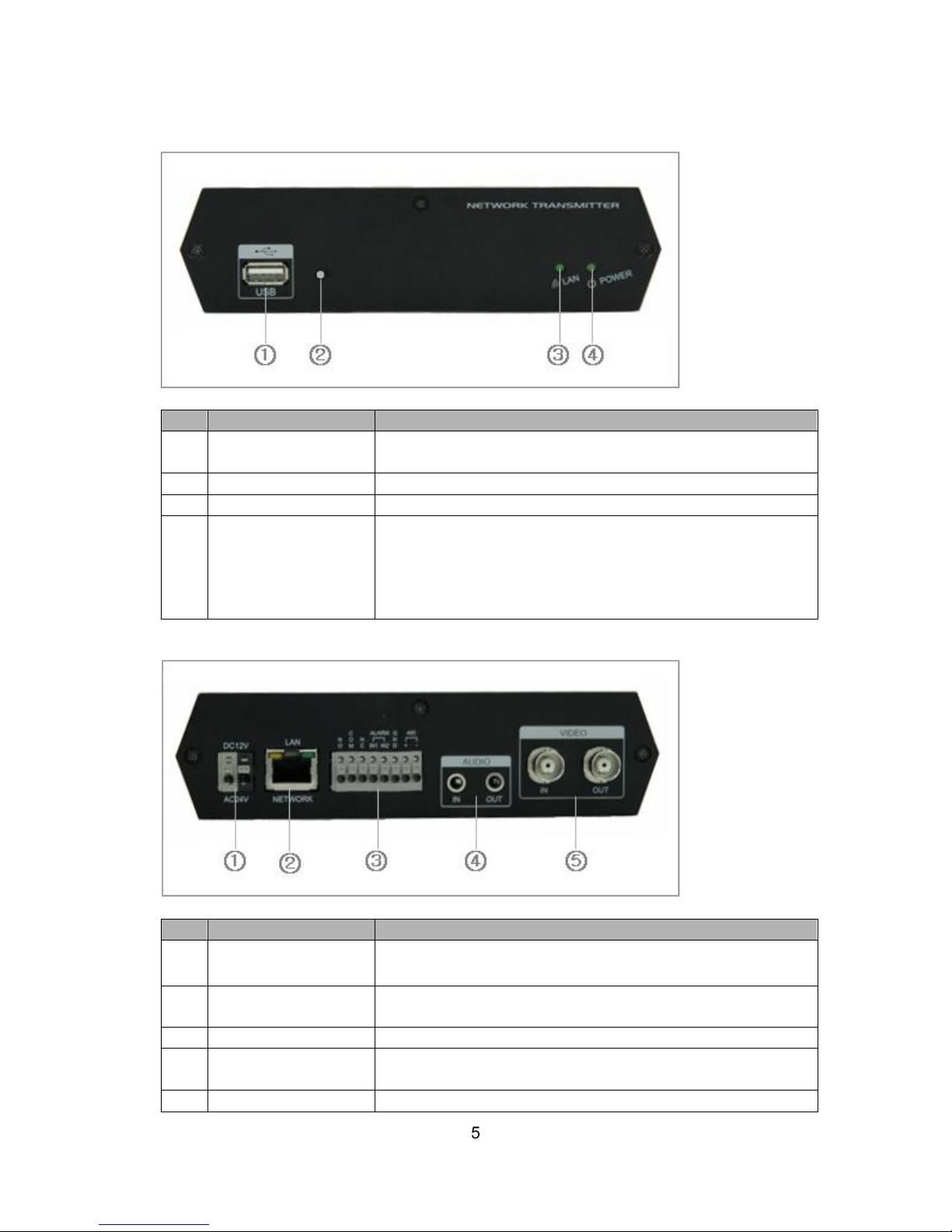
Overview
• Front Panel
NO
Function
Description
1
USB
One USB port is provided to connect external USB
memory stick for archiving video or system upgrade.
2
Reset Button
Press this button to restore the factory default settings
3
Network Indicator
Lights when a remote user is connected to the unit.
4
Power Indicator
Lights when the power is on.
Steady amber during booting and flash amber during
factory default.
Steady green for normal operation and steady red for
failed upgrade.
• Rear Panel
NO
Function
Description
1
Power adaptor
connector
Connects the supplied power adapter or an external
power supply 12V DC or 24V AC, max. 5W.
2
Network
connector(PoE)
RJ-45 port compatible with 10/100Mbps, which have a
PoE function.
3
8-pin I/O terminal
Connects RS485, alarm input and output.
4
Audio In/Out
Connects the port to the microphone and speaker, which
have an amplifier function.
5
Video In/Out
Connects the video input and output.
 Loading...