

Vista VIPER H4, VIPER-H5 User Manual

1
H264 4, 8 and 16 channel
NVR 1U
User manual

2
Please read this manual thoroughly before use and keep it handy for future reference.
3
Before You Begin
Read these instructions before installing or operating this product.
Note: This installation should be made by a qualified service person and should conform to local codes.
This manual provides installation and operation information. To use this document, you must have the following
minimum qualifications:
A basic knowledge of CCTV systems and components
A basic knowledge of electrical wiring and low-voltage electrical connections
Intended use
Only use this product for its designated purpose; refer to the product specification and user documentation.
Customer Support
For assistance in installing, operating, maintaining and troubleshooting this product refer to this document and any
other documentation provided. If you still have questions, please contact Norbain Technical Support and Sales:
Norbain SD, 210 Wharfedale Road, IQ Winnersh, Wokingham, Berkshire RG41 5TP, England.
UK +44 (0) 118 912 5000
Note: You should be at the equipment and ready with details before calling Technical Support.
Conventions Used in this Manual
Boldface or button icons highlight command entries. The following WARNING, CAUTION and Note statements
identify potential hazards that can occur if the equipment is not handled properly:
* WARNING:
Improper use of this equipment can cause severe bodily injury or equipment damage.
** Caution:
Improper use of this equipment can cause equipment damage.
Note: Notes contain important information about a product or procedure.
This apparatus is manufactured to comply with the radio interference.
A Declaration of Conformity in accordance with the following EU standards has been made. The
manufacturer declares that the product supplied with this document is compliant the provisions of
the EMC Directive 2004/108/EC, the CE Marking Directive 93/68 EEC and all associated
amendments.
All lead-free products offered by the company comply with the requirements of the European
law on the Restriction of Hazardous Substances (RoHS) directive: 2011/65/EU, which means
our manufacture processes and products are strictly “lead-free” and without the hazardous
substances cited in the directive.
The crossed-out wheeled bin mark symbolizes that within the European Union the product must
be collected separately at the product end-of-life. This applies to your product and any
peripherals marked with this symbol. Do not dispose of these products as unsorted municipal
waste.
* This symbol indicates electrical warnings and cautions.
** This symbol indicates general warnings and cautions.
NORBAIN SD reserves the right to make changes to the product and specification of the product from time to
time without prior notice.
WARNINGS AND CAUTIONS:
To reduce the risk of fire or electric shock, do not insert any metallic objects through the ventilation grills or
other openings on the equipment.
4
IMPORTANT SAFEGUARDS
1. Read these instructions.
2. Keep these instructions.
3. Heed all warnings.
4. Follow all instructions.
5. Do not use this apparatus near water.
6. Clean only with dry cloth.
7. Do not block any ventilation openings. Install in accordance with the manufacturer's instructions.
8. Do not install near any heat sources such as radiators, heat registers, stoves, or other apparatus (including amplifiers) that
product heat.
9. Do not defeat the safety purpose of the polarized or grounding-type plug. A polarized plug has two blades with one wider than
the other. A grounding type plug has two blades and a third grounding prong. The wide blade or the third prong is provided for
your safety. If the provided plug does not fit into your outlet, consult an electrician for replacement of the obsolete outlet.
10. Protect the power cord from being walked on or pinched particularly at plugs, convenience receptacles, and the point where
they exit from the apparatus.
11. Only use attachments/accessories specified by the manufacturer.
12. Unplug this apparatus during lightning storms or when unused for long periods of time.
13. Refer all servicing to qualified service personnel. Servicing is required when the apparatus has been damaged in any way,
such as power-supply cord or plug is damaged, liquid has been spilled or objects have fallen into the apparatus, the apparatus
has been exposed to rain or moisture, does not operate normally, or has been dropped.
14. CAUTION - THESE SERVICING INSTRUCTIONS ARE FOR USE BY QUALIFIED SERVICE PERSONNEL ONLY. TO
REDUCE THE RISK OF ELECTRIC SHOCK DO NOT PERFORM ANY SERVICING OTHER THAN THAT CONTAINED IN THE
OPERATING INSTRUCTIONS UNLESS YOU ARE QUALIFIED TO DO SO.
15. IEC60950-1/UL60950-1 or Certified/Listed Class 2 power source only.
CE COMPLIANCE STATEMENT
WARNING
This is a Class A product. In a domestic environment this product may cause radio interference in which case the user may be
required to take adequate measures.
CAUTION
RISK OF EXPLOSION IF BATTERY IS REPLACED BY AN INCORRECT TYPE.
DISPOSE OF USED BATTERIES ACCORDING TO THE INSTRUCTIONS.

5

VIPER-H4 user
manual V1.0
1
Table of Contents
Before You Begin 3
Intended use 3
Customer Support 3
WARNINGS AND CAUTIONS: 3
Table of Contents ................................................................................................................................. 1
1. Overview 4
1.1 Package Contents ...................................................................................................................... 4
1.2 Part Description ......................................................................................................................... 4
2. Installation 7
2.1 Installing HDD ........................................................................................................................... 8
2.2 System boot up.......................................................................................................................... 8
2.3 Quick set up .............................................................................................................................. 9
2.3.1 Account........................................................................................................................ 9
2.3.2 System ....................................................................................................................... 10
2.3.3 Network ..................................................................................................................... 11
2.3.4 Time/Date .................................................................................................................. 12
3. Live Screen Configuration 13
3.1 Icons in Live screen .................................................................................................................. 14
3.2 Live Launcher menu ................................................................................................................. 15
3.2.1 Backup (Down loading of video footage) ....................................................................... 16
3.3 Quick menu ............................................................................................................................. 17
3.3.1 PTZ Control ................................................................................................................ 18
3.3.2 Camera Registration .................................................................................................... 20
3.3.3 Status > System log .................................................................................................... 21
3.3.4 Status > Event............................................................................................................ 22
3.3.5 Status > Record .......................................................................................................... 23
3.3.7 Status > Disk.............................................................................................................. 24
4. Setup menu 25

VIPER-H4 user
manual V1.0
2
4.1 General buttons in Setup menu ................................................................................................. 28
4.2 SYSTEM .................................................................................................................................. 29
4.2.1 System ....................................................................................................................... 29
4.2.2 Time/Date .................................................................................................................. 31
4.2.3 Account > User ........................................................................................................... 34
4.2.5 Configuration (Config) ................................................................................................. 36
4.3 CAMERA .................................................................................................................................. 38
4.3.1 Basic .......................................................................................................................... 38
4.3.2 Advanced (Video, Stream and VCA) .............................................................................. 41
4.4 DEVICE ................................................................................................................................... 42
4.4.1 Display ....................................................................................................................... 42
4.4.2 Disk > Setup .............................................................................................................. 46
4.4.3 PTZ > PTZ ................................................................................................................. 49
4.4.4 Serial Device > Serial Device (PTZ, keyboard, or Text device) ......................................... 50
4.4.5 TEXT > TEXT ............................................................................................................. 51
4.5 RECORD .................................................................................................................................. 53
4.5.1 Schedule > Schedule ................................................................................................... 53
4.5.2 Stream ....................................................................................................................... 56
4.6 EVENT .................................................................................................................................... 60
4.6.1 System/Disk ............................................................................................................... 60
4.6.2 Alarm In ..................................................................................................................... 62
4.6.3 Motion ....................................................................................................................... 65
4.6.4 Video Loss > Setup ..................................................................................................... 67
4.6.5 Notification ................................................................................................................. 68
4.7 NETWORK ............................................................................................................................... 70
4.7.1 Basic .......................................................................................................................... 70
4.7.2 DVRNS/DDNS ............................................................................................................. 72
4.7.3 E-Mail ........................................................................................................................ 74
4.7.4 Warp ......................................................................................................................... 75
5. Search/Play 76
5.1 Search .................................................................................................................................... 76
5.2 Playback.................................................................................................................................. 82
6. Webviewer 83
7. Products Specifications 85

VIPER-H4 user
manual V1.0
3
VIPER-H4 user
manual V1.0
4
1. Overview
1.1 Package Contents
The device package contents consist of the following:
Note
Please check all components involved.
Table 1-1 Package contents
No
Name
No
Name
1
NVR 4 DC Power supply
2
CD (Manuals and Client software)
5
Quick guide
3
Mouse
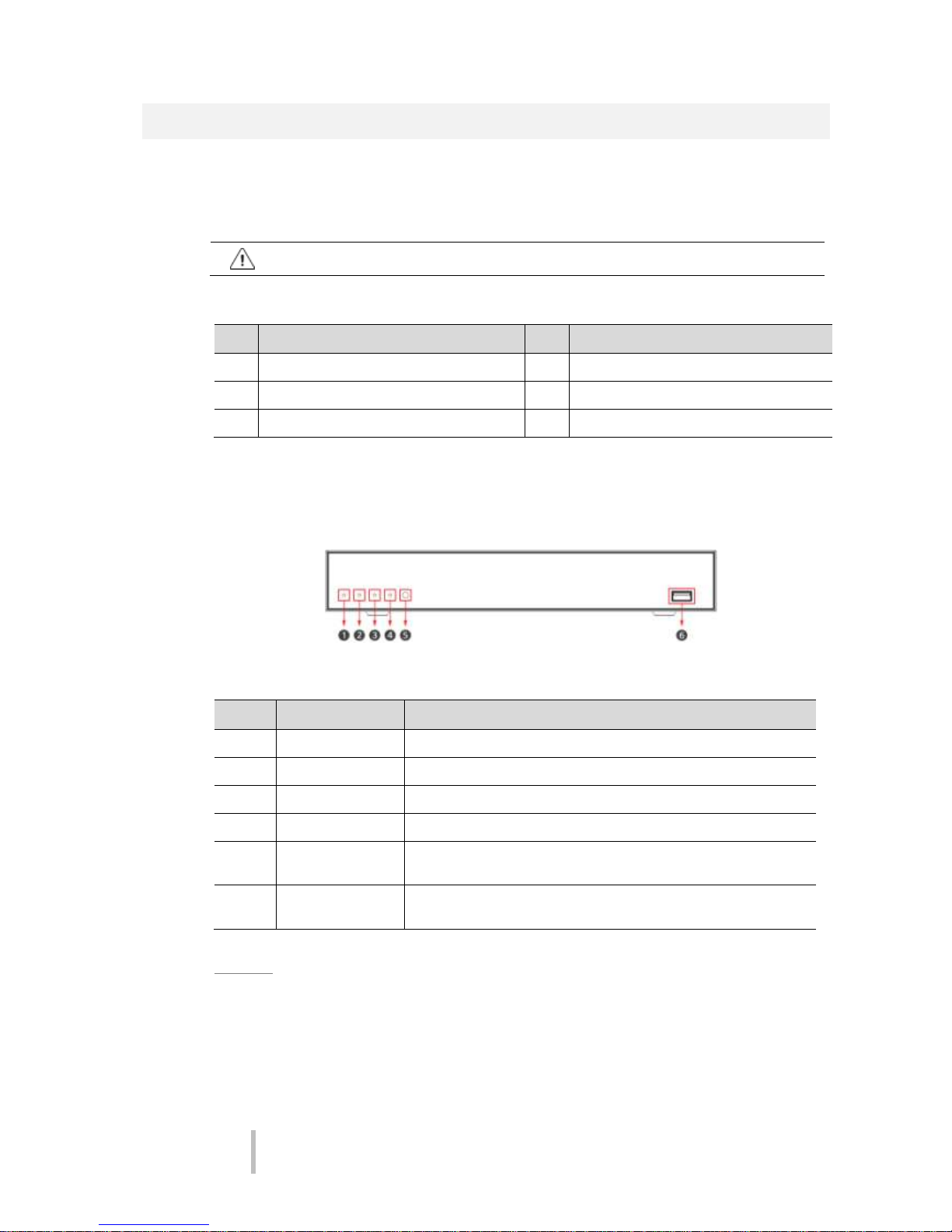
1.2 Part Description
Each part is listed in the below:
Figure 1-1 Name and Connection of each front section
Table 1-2 Name and Function of each front section
No.
Name
Function
1
PWR
Illuminated when power is on
2
REC
Illuminated if recording is in progress
3
PB
Illuminated if playback is in progress
4
NET
Illuminated if connected via network
5
IR Remote Control
Sensor
Receives all incoming signals from the remote control.
6
USB port
For connection of Mouse and USBdrives for download and firmware
upgrading
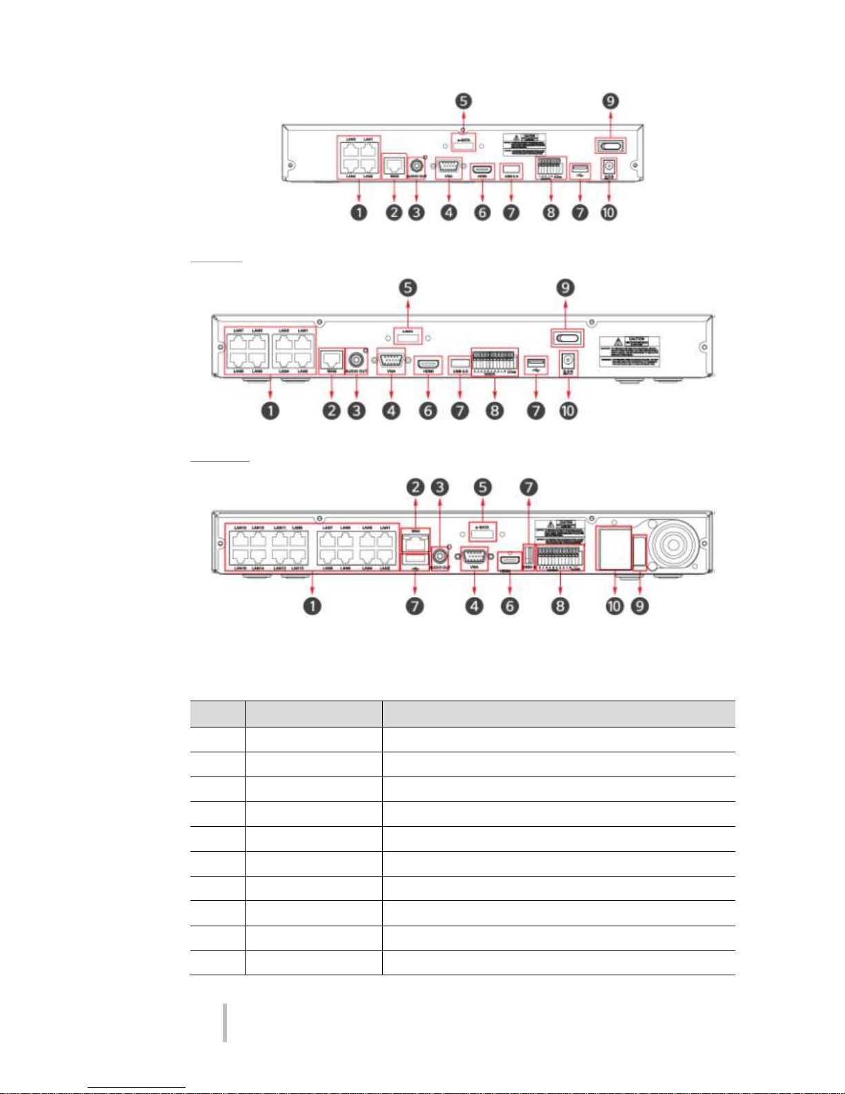
4ch NVR
VIPER-H4 user
manual V1.0
5
8ch NVR
16ch NVR
Figure 1-2 Name and Connection of rear section of 4ch, 8ch and 16ch NVR
Table 1-3 Name and Function of rear section of 4ch, 8ch and 16ch NVR
No.
Name
Function
1
IP CAM / PoE
IP camera input port, IEEE802.3af PoE supported
2
Network
Network connector
3
Audio Out
Audio output port
4
VGA
VGA output port
5
e-SATA
e-SATA storage connection connector
6
HD Output
HD output port 7 USB
USB port is connected for data back-up
8
Alarm In/Out
Alarm connector
9
Power Switch
On/Off the Power
10
Power Input
Connect power supply

VIPER-H4 user
manual V1.0
6
VIPER-H4 user
manual V1.0
7
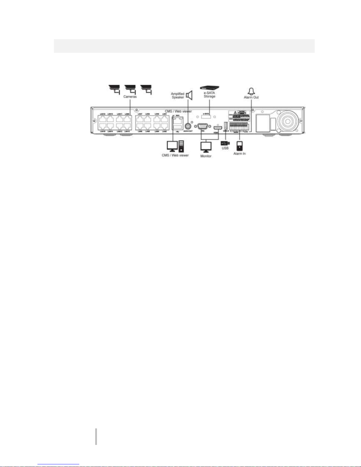
2. Installation
Connect external devices as per the diagram below.
Figure 2-1 Connection map
VIPER-H4 user
manual V1.0
8
2.1 Installing HDD
Note: Hard disk drives are factory fitted.
Attention
Withdraw the mains plug before installing HDD to reduce the risk of injury or
electrical shock, or device malfunction.
Make sure to check the compatibility of HDD with the device.
1
Always switch off and unplug the unit.
2
Unscrew with a screw driver (+) and open the unit cover.
3
Install HDD in the bottom case.
4
Connect a data cable and power cable with HDD.
5
Close the cover and tighten screws.
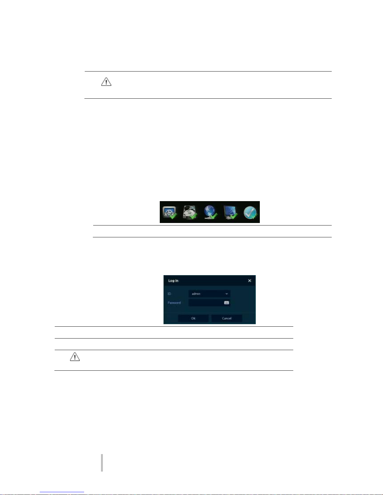
2.2 System boot up
1
When initially powered up the NVR will display the following icons in order.
Note
Installing new HDD might take more initialize time.
2 When fully booted a buzzer will sound and the live screen will be displayed
3 In Log in screen, enter the ID, Password and press OK.
Note
Default ID & Password is admin/admin
Attention
Please change password after login due to security.

VIPER-H4 user
manual V1.0
9
2.3 Quick set up
2.3.1 Account
1. Click the keyboard icon to set ID and Password for users.
2. With keyboard UI, set the ID and Password, and press OK.
3.Press the Save button to save newly set ID and Password.
4. Press Next button to move to the next set up stage
Note
Default ID/Password is admin/admin.
Change the password for security.
Maximum 16 characters

VIPER-H4 user
manual V1.0
10
2.3.2 System
1
Set each item in System setting screen.
Language: Select system language.
Device Name: Enter the device name.
Keyboard ID: The RS485 Address for control via a remote keyboard
Selecting the device ID. ensure that the each devise has a unique ID
HD Output / VGA: Set resolution of the monitor connected to the device.
2
Press Save button.
Press Next to move to the next set up stage

VIPER-H4 user
manual V1.0
11
2.3.3 Network
1
Set each item in Network setting screen.
WAN Port: Select whether to use static IP or dynamic IP.
IP Address, Subnet Mask, Gateway, DNS, and Port: As for dynamic IP, enter information in each
space.
2
Press Save button to save set value.
3
Press Next to move to the next set up stage

VIPER-H4 user
manual V1.0
12
2.3.4 Time/Date
1
Set each item in Time/Date setting screen.
Network Time Sync: Select network for synchronizing with time server.
System Time: Not for synchronizing with network time server, set the device time; otherwise
(applying for Daylight saving time), select DST.
Time Zone: Select time zone for the system being installed.
DST Start/End: For applying Daylight saving time, set the application period.
2
Press Save button to save set value.
3
Press Next to move to the next set up phase
VIPER-H4 user
manual V1.0
13
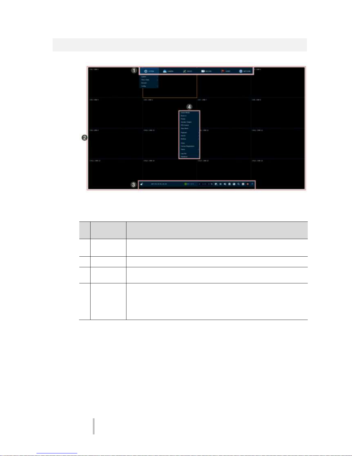
3. Live Screen Configuration
Figure 3-1 UI Screen Configuration
Table 3-1 Items and Description of UI Screen Configuration
No
.
Item
Description
1
Setup menu
Setting menu is located on the top edge of the screen. See section “04 Setup ”
for more detailed information
2
Live screen
Show live video of connected cameras.
3
Launcher
menu
Launcher menu is located on the bottom edge of screen. See section “3.2 Live
Launcher ” for more detailed information.
4
Quick menu
Clicking the right mouse button to display the Quick menu. See
section “0
3.1.1 Backup (Down loading of video footage)

VIPER-H4 user
manual V1.0
14
No
.
Item
Description
Figure 3-4 Backup
Table 3-4 Backup Item and Description
No.
Item
Description
1
Select CH
Select the channels to be downloaded
2
Select All/
Unselect All
Select or clear all channels.
3
Start
Setting back-up start time (Bookmark: bookmark list).
4
End
Setting back-up end time (Bookmark: bookmark list).
5
Time Overlap
Selecting the device to save back-up files to.
6
Backup Mask
Press to search for back up devices ( e.g. USB pens)
7
Device
Entering a folder name to save back-up files
8
Reload
Selecting a file format to back-up (AVI or H4V)
9
Folder Name
Calculates the size of file to be to backed-up
10
File format
Formatting the USB device ( Will remove any information from the USB
device)
11
Calculate
Start the back-up process
12
Format
Close the backup screen
13
Start
Select the channels to be downloaded
14
Cancel
Select or clear all channels.
Quick ” for more detailed information.
VIPER-H4 user
manual V1.0
15
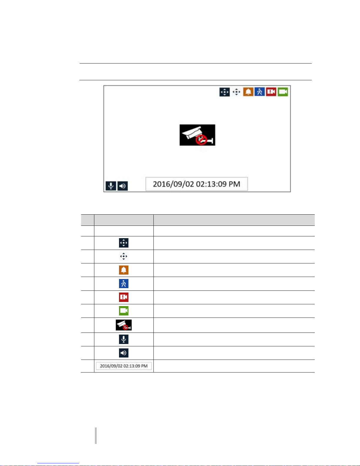
3.2 Icons in Live screen
Note
Chosen live screen is framed by a blue border; the segment that the mouse is
located in is framed by a yellow border.
Figure 3-2 Live screen icon
Table 3-2 Live screen icon and its description
No.
Icon
Description
1
CH1 CAM1
Channel numbers and camera titles
2 A camera with PTZ function
PTZ control function in process
Recording in alarm event mode
Recording in motion event mode
Recording in panic recording mode
Recording in consecutive recording mode
3 Video loss icon
4 Mic ON/OFF
Speaker ON/OFF
6
Displaying present date and time
VIPER-H4 user
manual V1.0
16
3.3 Live Launcher menu
This chapter describes Launcher menu located at the bottom of the screen.
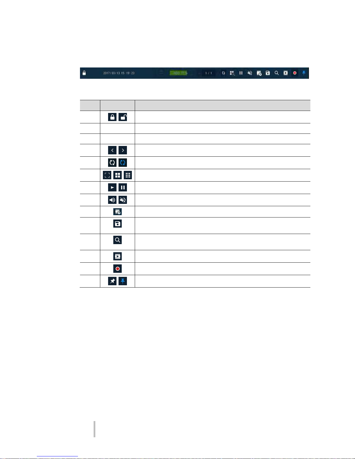
Figure 3-3 Launcher menu
Table 3-3 Launcher menu Item and Description
No.
Item
Description
1
Log in/out status and logged in ID
2
Date & Time
Displaying present date and time
3
HDD
Displaying HDD capacity currently used
4
Moving to previous/next partition screen
5
Live screen sequence mode (toggle ON / OFF)
6
Selecting split screen mode (single screen, 4-, 9-, and 16- partition)
7
Freeze live image (toggle ON / OFF)
8
Audio selection (toggle ON / OFF)
9
Pin Interest – tags video with easily searched markers
10
Make a backup video of users want. See “0 ” to display detailed information
about back-up.
11
Searching recording data (time, event, and thumbnail). See “5.1 Search” to
display detailed information about search.
12
Go to Playback mode
13
Panic record mode
14
Locking or releasing launcher menu (toggle ON /OFF)
VIPER-H4 user
manual V1.0
17
3.3.1 Backup (Down loading of video footage)
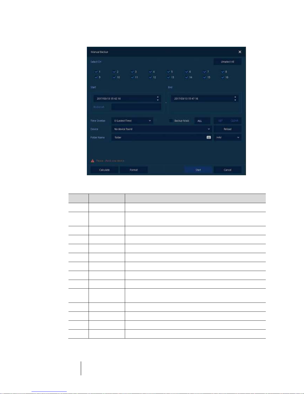
Figure 3-4 Backup
Table 3-4 Backup Item and Description
No.
Item
Description
1
Select CH
Select the channels to be downloaded
2
Select All/
Unselect All
Select or clear all channels.
3
Start
Setting back-up start time (Bookmark: bookmark list).
4
End
Setting back-up end time (Bookmark: bookmark list).
5
Time Overlap
Selecting the device to save back-up files to.
6
Backup Mask
Press to search for back up devices ( e.g. USB pens)
7
Device
Entering a folder name to save back-up files
8
Reload
Selecting a file format to back-up (AVI or H4V)
9
Folder Name
Calculates the size of file to be to backed-up
10
File format
Formatting the USB device ( Will remove any information from the USB
device)
11
Calculate
Start the back-up process
12
Format
Close the backup screen
13
Start
Select the channels to be downloaded
14
Cancel
Select or clear all channels.
VIPER-H4 user
manual V1.0
18
3.4 Quick menu
Right click anywhere on the screen to display the Quick menu.
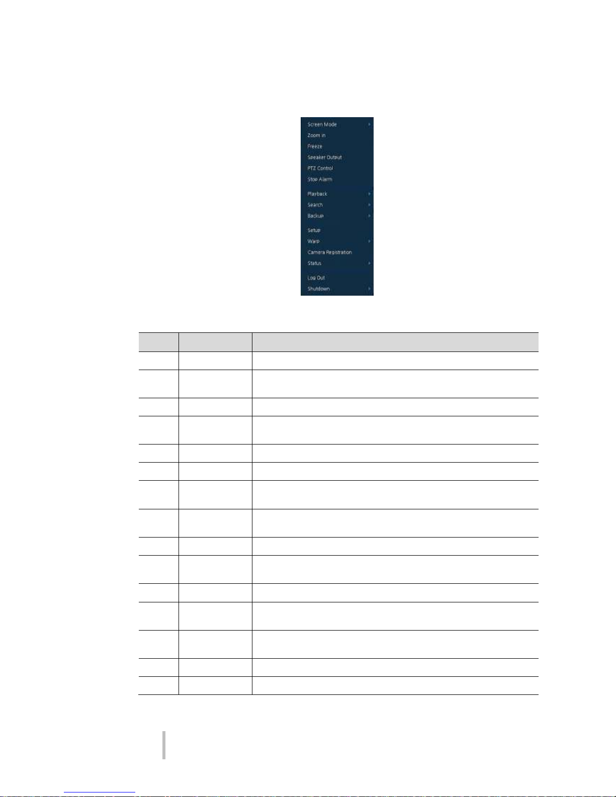
Figure 3-5 Quick menu
Table 3-5 Quick menu Item and Description
No.
Item
Description
1
Screen Mode
Select the split screen mod to be displayed (Full, 2X2, 3X3, and 4x4).
2
Zoom in
Magnify the selected live full screen image (Zoom out, 2 times, 4 times,
and 8 times).
3
Freeze
Freezes the video selected live screen images (toggle on / off).
4
Speaker
Output/Mute
Turning on/off a sound speaker
5
PTZ Control
Controlling PTZ Function
6
Stop Alarm
Stop the alarm sounder
7
Playback
Playing selected live screen images (from 30 sec, 1 min, 5 min, 10 min, 30
min, 1-hour, Go to last play time, and Go to last record time)
8
Search
Go to the search screen (time, event, thumbnail, and text). See section
“5.1 Search” for more detailed information.
9
Backup
Go to the Back up screen. See section “0 ” for more detailed information
10
Setup
Opens the DVRs main set up menu. For more information about set up
menu, see section “4 Setup .”
11
Warp
Monitor and control for remote recorder.
12
Camera
Registration
Opens a pop-up displays IP camera registration.
13
Status
Opens a pop-up menu showing: device system log, event, and recording
status (system log, event, and record).
14
Log in/Log out
Log in/Log out.
15
Shutdown
Shuts down or restarts the device (shutdown, restart).
VIPER-H4 user
manual V1.0
19
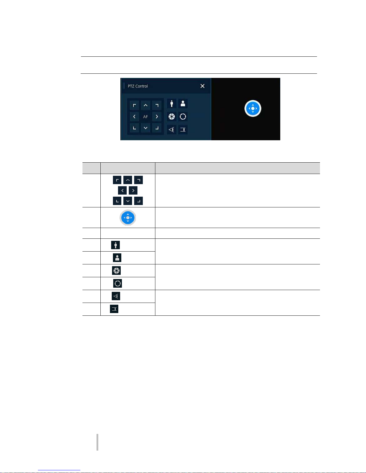
3.4.1 PTZ Control
Note
PTZ Control menu can be displayed if relevant channel’s protocol is set in DEVICE >
PTZ in the upper live screen.
Figure 3-6 Quick menu > PTZ Control
Table 3-6 Quick menu > PTZ Control Item and Description
No.
Item
Description
1
Direction control buttons
2 Place cursor on this spot , click and drag to make PTZ camera move
3
AF
Adjusting screen focus automatically
4
Zoom Out
Zoom function of PTZ camera
5
Zoom In
6
IRIS OFF
Iris adjustment
7
IRIS On
8
Focus Far
Manual focus adjustment
9
Focus Near

VIPER-H4 user
manual V1.0
20
In PTZ Control screen, clicking the right button of the mouse displays Quick menu.
Figure 3-7 PTZ Control Quick menu
Table 3-7 PTZ Control Item and Description in Quick menu
No.
Item
Description
1
Preset Go
Go to a preset position
2
Preset Save
Save a preset position
3
Tour
Run Tour function.
4
Scan
Run Scan function.
5
Pattern
Run Pattern function.
6
Exit
Exit to live screen menu in PTZ Control menu
VIPER-H4 user
manual V1.0
21
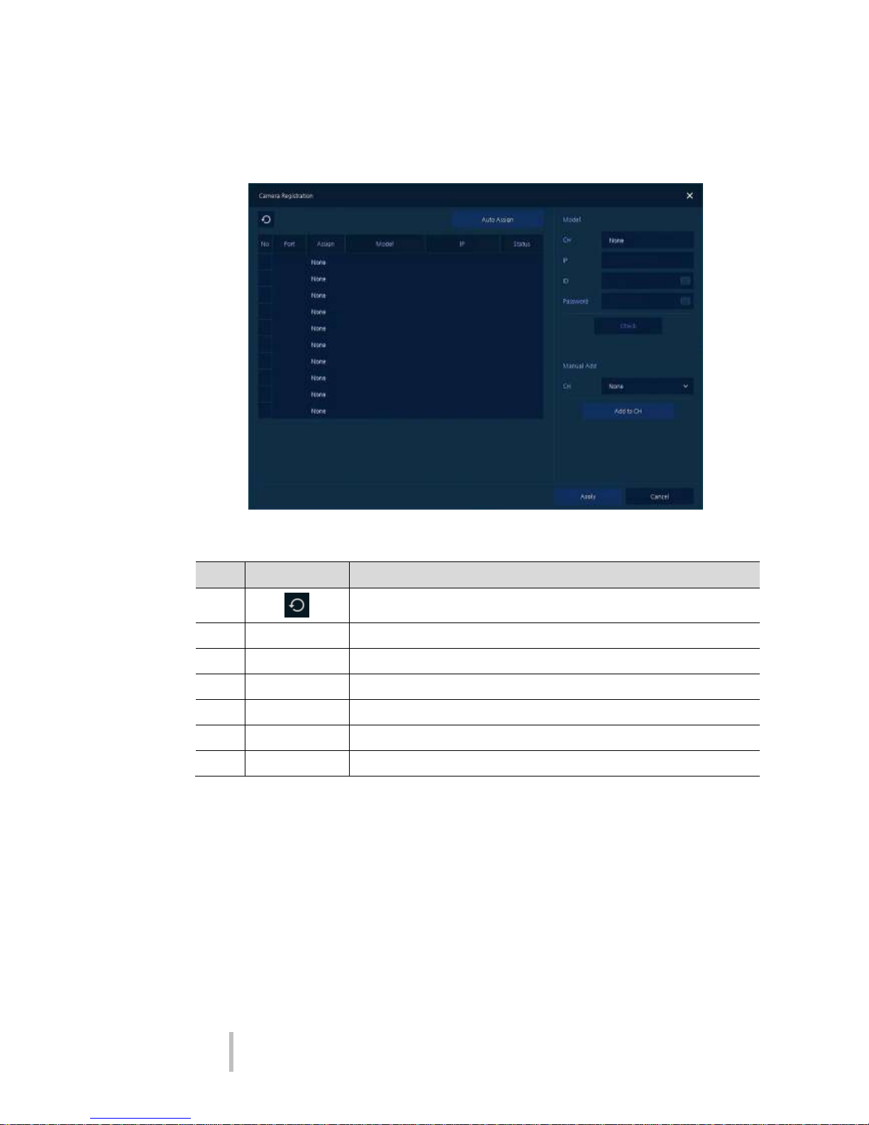
3.4.2 Camera Registration
Connection of IP camera to the NVR
Figure 3-8 Quick Menu > Camera Registration
Table 3-8 Quick Menu > Camera Registration Item and Description
No.
Item
Description
1 Search for connected IP cameras.
2
Auto Assign
Automatically assign channel numbers
3
Port
Show the detected camera port (WAN or PoE).
4
Assign
Selecting the channel windows manually.
5
Model
Show detected camera model number.
6
IP
Show detected camera IP address.
7
Status
Show connection status.
VIPER-H4 user
manual V1.0
22
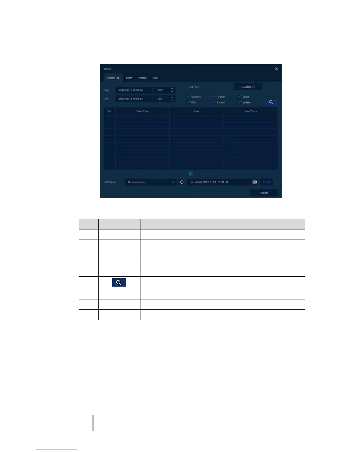
3.4.3 Status > System log
The system log information can be seen in the System log tab in Status screen.
Figure 3-9 Status > System log in Quick menu
Table 3-9 Status of Quick menu > System log Item and Description
No.
Item
Description
1
Start
Set the starting time of system log to be searched
2
End
Set the end time of system log to be search
3
Log Type
Selecting log types (Network, Record, Setup, Disk, Backup, and System)
4
Select All
/Unselect All
Selecting or clearing all log types (toggle).
5 Pressing search button search on the basis of set condition
6
System log list
Displays system log lists
7
USB Export
Export the log data to USB thumb drive.
8
Cancel
Exit

VIPER-H4 user
manual V1.0
23
3.4.4 Status > Event
The real-time event information of the unit in Event tab in Status screen.
Figure 3-10 Status > Event in Quick menu
Table 3-10 Status > Event Item and Description in Quick menu
No.
Item
Description
1 Temporary fixing or releasing an event list (toggle).
2
Refresh
Deleting the event list
3
Event list
Displaying the event list
4
Cancel
Exit the status screen
 Loading...