

Vista VFD-MiniD Installation Manual
VFD-MiniD Vari-Focal Dome
Installation Manual
Pb
Table of Content
1.
2.
3.
4.
5.
6.
7.
Appendix:
Approximate Recording Time Table
Mounting Template
Regulatory Compliance
Precautions
Installation Guide
3.1 Methods for mounting
3.2 Preparations for the installation
3.3 Adjust camera and replace dome cover
3.4 Insert miniSD card
3.5 Complete the installation
3.6 Installation guide
Camera Adjustment
Specification
OSD Menu Tree
OSD Menu Instruction
...................................................................................................... 1
.......................................................................................................................... 2
................................................................................................................ 3
.............................................................................................................. 3
............................................................................................. 4
................................................................................ 5
................................................................................................................ 6
............................................................................................................ 6
................................................................................................................... 7-8
............................................................................................................ 9
..................................................................................................................... 10-11
............................................................................................................... 12
...................................................................................................... 13-16
8.
Screen Mode ................................................................................................................. . 17
9.
Search Mode ................................................................................................................. . 18
Compliance
1
Before you begin
Read these instructions before installing or operating this product.
Note: This installation should be made by a qualified service person and should conform to local codes.
This manual provides installation and operation information.
To use, you must have the following minimum qualifications:
*A basic knowledge of CCTV systems and components
* A basic knowledge of electrical wiring and low-voltage electrical connections.
Intended Use
Only use this product for its designated purpose; refer to the product specification and user documentation.
Customer Support
For assistance in installing, operating, maintaining and troubleshooting this product, refer to this document and any
other documentation provided. If you still have questions, please contact Norbain Technical Support and Sales:
210 Wharfedale Road, Winnersh Triangle, Wokingham, Berks, RG41 5TP, UK.
0118-912-5000
Note: You should be at the equipment and ready with details before calling Technical Support.
Conventions
Boldface or button icons highlight command entries. The following Warning, Caution, and Note statements identify
potential hazards that can occur if the equipment is not handled properly.
Warning:
Improper use of this equipment can cause severe
bodily injury or equipment damage.
Caution:
Improper use of this equipment can cause
equipment damage.
Note: Notes contain important information about a product or procedure.
Equipment Disposal:
Within in the European Union, products marked
with the WEEE logo cannot be disposed of as
unsorted municipal waste. Upon the purchase of
equivalent new equipment, return this product to
your local supplier or dispose of it at designated
collection points. For more information,
please visit www.recyclethis.info or
www.vista-cctv.com/weee/
RoHS Announcement
All lead-free products offered by the company comply
with the requirements of the European law on the
Restrictions of Hazardous Substances (RoHS) directive,
which means our manufacture processes and products
are strictly “lead-free” and without the hazardous
substances cited in the directive.
CE Mark
This apparatus is manufactured to comply with the radio interference. European representative for
manufacture (EMC): Norbain Ltd., 210 Wharfedale Road, Winnersh Triangle, Workingham, Berks, RG41 5TP, UK.
* This symbol indicates electrical warnings and cautions.
**This symbol indicates general warnings and cautions.
Warnings and Cautions
To reduce the risk of fire or electric shock, do not
insert any metallic objects through the ventillation
grills or other openings on the equipment.
**NORBAIN SD LTD reserves the right to make changes to the product and specification of the product from time to time
without prior notice
Precautions
2
Precautions
•
•
•
Safety
Installation
Cleaning
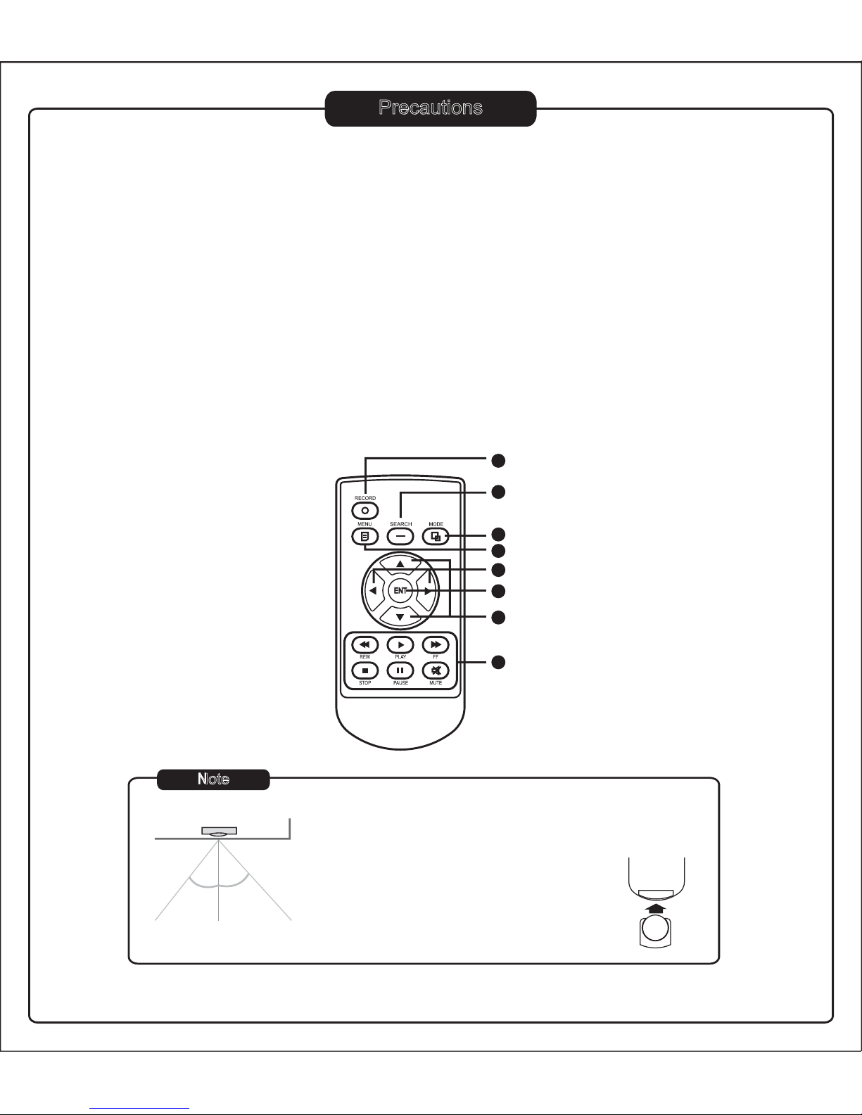
Get to know the Remote ControllerPacking List
In addition to this installation sheet:
•
•
•
•
•
•
Torx driver x 1
D5 fixing screws x 3
T6 fixing screw x 1
Wall plugs x 3
Cable entry robber grommet
(3/4”, for dome base use) x 1
Remote Controller x 1
UP/DOWN: Move up and down on OSD menu or
increase/ decrease a value.
ENT : Select and save changed values.
SEARCH: To view the first frame when an event occurs.
RECORD: To start and stop recording.
PLAY CONTROL: REW / PLA Y / FF / STOP / PAUSE / MUTE
LEFT/RIGHT : To rewind & forward or move the cursor right/ left.
MODE: To toggle between live mode and playback mode.
Front view
4
5
3
6
7
8
1
2
MENU: To display the OSD menu on screen.
* When using the remote control, point it at IR receiver on the board.
* IR receiver operation range should be within 60° for horizontal angle
and the distance of Max. 6m. (See image left)
* When the remote control does not work, replace
its battery on the rear. (See image right)
* Button Cells Battery : CR2025 / 3V
+
Note
IR Receiver
30° 30°
6m
Operation Range
Rear
- Should any liquid or solid object fall into the unit, unplug it and have it checked by a qualified person
before operating again.
- Unplug the unit from the wall outlet if it is not going to be used for several days. To disconnect the cord, pull it out
by the plug , never by the cord itself.
- Allow adequate air circulation to prevent internal heat build-up. Do not place the unit on surfaces(rugs, blankets, etc).
- The height and linearity controls located at the rear panel are for adjustment by qualified personnel only.
Do not install the unit in extremely hot or humid environments or places exposed to excessive dust or mechanical
vibrations.
Clean the unit with a slightly damp soft cloth. Use a mild household detergent. Never use strong solvents such
as thinner or benzene as they might damage the finish of the unit.
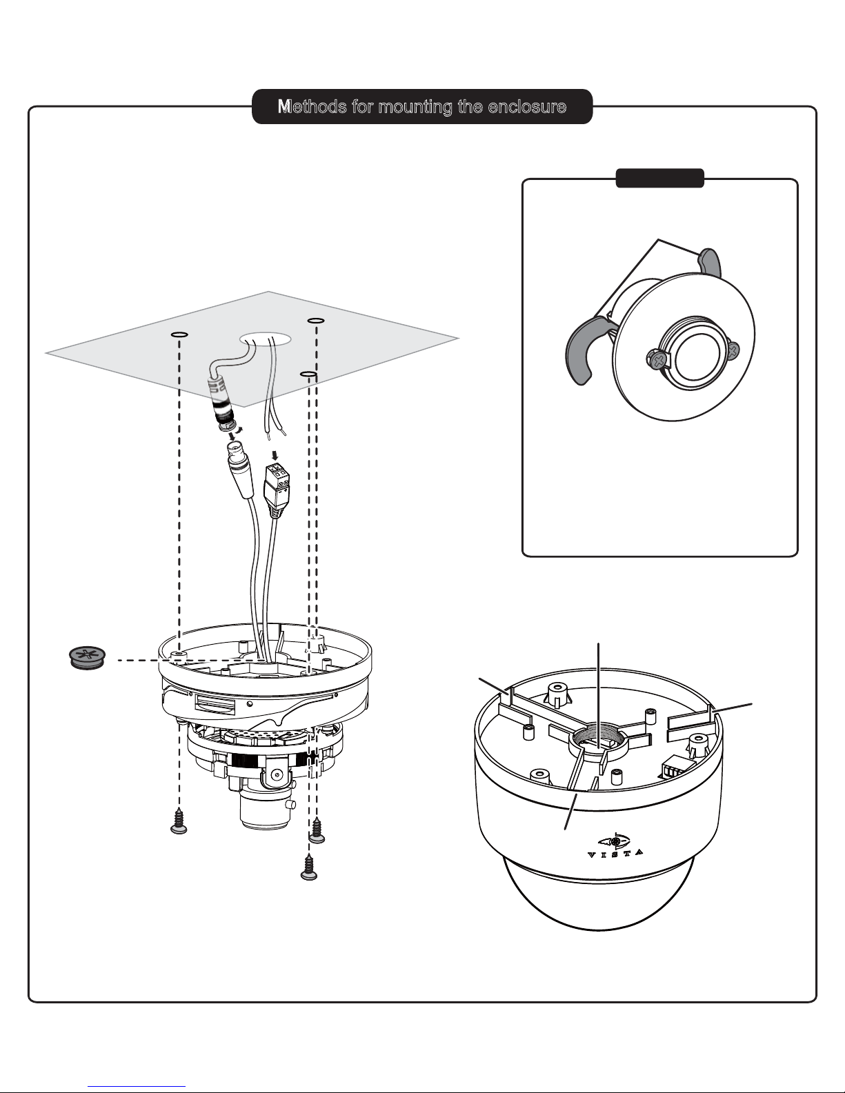
Methods for mounting the enclosure
3
A. Methods for mounting the enclosure
D5
D5
D5
First loosen the screws (B1), but not remove
them, to extend the locking arms. Then tighten
the screws sufficiently to compress the arms
to adjust to the mounting surface; however,
DO NOT OVERTIGHTEN.
B1
B
1
Locking Arms
Optional
B
C
C3
C3
C3
C2
C2
C2
C1: Threaded base
C2: Screw access holes
C3: Side knock-outs
C1
There are two ways to mount the dome enclosure:
A: By using the base mounting holes (C2)
B: By using the quick install adaptor (see fig B, optional)
Mounting Surface
A1
A2
A2
A2
A1: 3/4” Rubber Grommet
A2: D5 fixing screws
Note: Please note that Alarm/RS485 cable cannot be made
through the pipe if method B is used.
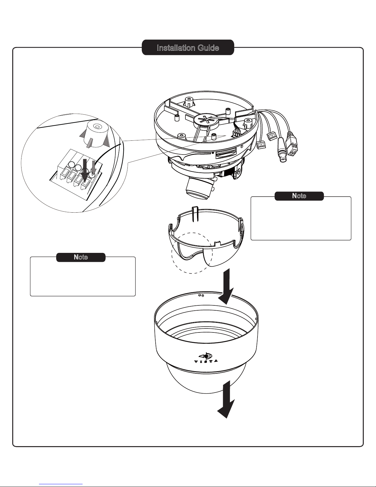
Installation Guide
4
D1: Dome Base
D2: Camera Liner
D3: Lens Opening
D4: Dome Cover
D. Preparations for the installation
D1
D2
D4
D3
D5
D6
D8
D7
D5: PIN 4 GND
D6: PIN 3 Alarm In
D7: PIN 2 RS485-
D8: PIN 1 RS485+
Push down to unlock (1) and insert
the connector (2).
(1)
(2)
Terminal Connector
Note
To remove the camera liner, hold
along the lends opening (D3)
and gently pull it away from the
dome base.
Note
This Alarm/ RS485 cable is
non-factory part and not
included with the product
package.

Installation Guide
5
E. Adjust camera and replace dome cover
E3
E4
E5
E1: Power Input Connector
E2: Video Output Connector
E3: Notches (on both sides)
E4: Camera liner
E5: Dome cover
Push the camera liner up to the
base until it clicks into place.
Mounting Surface
E2
E1
 Loading...