


Air Handler
Owner's Manual
Commercial Air Conditioners
Thank you for choosing Commercial Air Conditioners, please read this
owner’s manual carefully before operation and retain it for future reference.


Contents
1. Specications of the Air Handlers ...................................................................................... 1
1.1 Physical Dimension
1.2 General Information
2. Pre-Installation Instruction
2.1 Checking Product Received
2.2 Before Beginning Installation
2.3 Codes & Regulations
2.4 Replacement Parts
3. Important Safety Instructions
3.1 Recognize Safety Symbols, Words, and Labels ...................................4
3.2 Unit Inspection
4. Location
5. Ductwork ..................................................................................................6
6. Electric Heat
.....................................................................................................5
..............................................................................................6
...............................................................................1
............................................................................... 1
........................................................................ 3
..................................................................3
................................................................ 3
............................................................................ 3
............................................................................... 4
................................................................... 4
...................................................................................... 5
6.1 “VAFd” Electric Heater Kits Available
6.2 “VAFd” Heater Kits Installation
7. Electrical Supply Wire and MOP
7.1 Inspection of the Building Electrical Service
7.2 Wire Sizing
7.3 Maximum Overcurrent Protection (MOP)
7.4 Electric Connections-Supply Voltage
.........................................................................................10
.............................................................8
...............................................................9
..................................................8
................................................. 11
......................................... 9
........................................... 11


7.5 Schematic Wiring Diagram ................................................................. 12
7.6 Thermostat Wiring
8. Refrigerant Pipe.......................................................................................13
8.1 Piping Preparation
8.2 Special Instructions
9. Drain Pan Ret
10. Condensate Removal
11. Start-Up Procedure
12. Regular Maintenance
..............................................................................13
.............................................................................. 13
............................................................................14
........................................................................................15
............................................................................ 16
............................................................................... 16
...........................................................................17
Air Handler
C
E
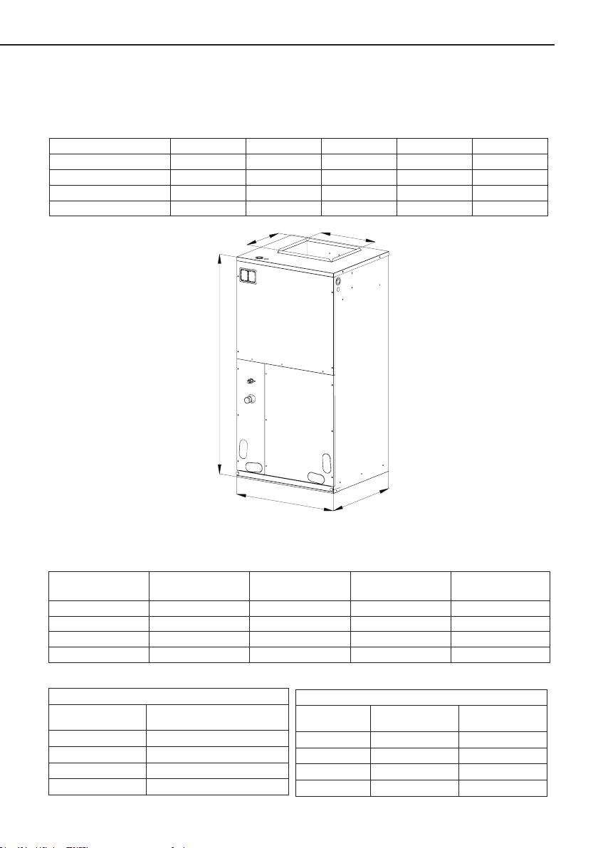
1. Specications of the Air Handlers
1.1 Physical Dimension
table 1 Unit: Inch
Model A B C D E
VAF-24A308I 21" 21-5/16" 10-3/4" 11-5/16" 43-1/2"
VAF-36A308I 21" 21-5/16" 12-1/4" 11-5/16" 48-3/16"
VAF-42A308I 24-1/2" 21-5/16" 13-3/4" 11-1/2" 48-3/16"
VAF-55A308I 24-1/2" 21-5/16" 13-3/4" 11-1/2" 48-3/16"
D
1.2 General Information
Model Cooling capacity Blower (inch)
VAF-24A308I
VAF-36A308I
VAF-42A308I
VAF-55A308I
Model Filter size (inch)
VAF-24A308I
VAF-36A308I
VAF-42A308I
VAF-55A308I
table 3 table 4
2.0 Ton 9.5×8 706 0-10
3.0 Ton 10×10 1150 0-20
3.5 Ton 11×11 1300 0-20
4.5 Ton 11×11 1420 0-20
Filters
19-5/16"X21-1/8"X1"
19-5/16"X21-1/8"X1"
20-5/16"X23"X1"
20-5/16"X23"X1"
A
Figure 1
table 2
VAF-24A308I 126/135lb. 154
VAF-36A308I 139/152lb. 112
VAF-42A308I 163/178lb. 81
VAF-55A308I 163/178lb. 81
B
Nominal SCFM
Model Net Wt/Gross Wt
Shipping Data
1
Electric heat(kw)
Loading QTY(40’
Container)
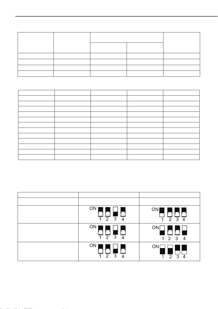
table 5
Air Handler
Motor @ 230V 1Ph 60Hz
HP FLA
DD Blower Wheel
(inch)
Model
VAF-24A308I
VAF-36A308I
VAF-42A308I
VAF-55A308I
Airow Tonnage
Range
2.0 1/17 0.52 9.5×8
3.0 1/2 3.6 10×10
3.5 3/4 4.6 11×11
4.5 3/4 4.6 11×11
The air ow of indoor unit
table 6
Model VAF-24A308I VAF-36A308I VAF-42A308I VAF-55A308I
ESP(in.wg) Air volume(CFM) Air volume(CFM) Air volume(CFM) Air volume(CFM)
0 808.4 1287.9 1377.4 1504.5
0.04 776.2 1250.8 1367.8 1483.8
0.08 742.1 1218.0 1339.6 1462.7
0.12 706.8 1181.2 1326.8 1441.6
0.16 666.6 1147 1300.4 1420.5
0.2 623.4 1113.1 1288.6 1400.6
0.24 576.4 1083.0 1271.4 1379.4
0.28 514.1 1055.8 1242.8 1357.8
0.32 452.3 1014.8 1214.3 1335.3
0.36 384.2 963.1 1208.1 1312.1
0.4 306.4 906.5 1182.5 1288.5
Notes:
Based upon W/nominal tonnage, dry coil and lter should be installed.
①
Use 0.96 as approximate CFM correction factor for wet coil.
②
See the following table for how to set the DIP switch of the unit VAF-36A308I and VAF-42A308I:
table 7
Model/DIP Switch COOL HEAT
VAF-24A308I
/ /
VAF-36A308I
VAF-42A308I
VAF-55A308I
Note: The black part presents the switch rod.
2
Air Handler
2. Pre-Installation Instruction
2.1 Checking Product Received
After receiving the product, please check if there is any damage caused by transportation.
Shipping damage is the responsibility of the carrier. Verify the model number, specications and
accessories are correct prior to installation. The distributor or manufacturer will not accept claims
from dealers for transportation damage or installation of incorrectly shipped units.
2.2 Before Beginning Installation
Carefully read all instructions for the installation prior to installing product. Make sure each step
or procedure is understood and any special considerations are taken into account before starting
installation. Assemble all tools, hardware and supplies needed to complete the installation. Some
items may need to be purchased locally. Make sure everything needed to install the product is on
hand before starting.
2.3 Codes & Regulations
DANGER
IMMEDIATE HAZARDS WHICH WILL RESULT IN PROPERTY DAMAGE, PRODUCT
DAMAGE, SEVERE PERSONAL INJURY OR DEATH.
WARNING
HAZARDS OR UNSAFE PRATICES COULD RESULT IN PROPERTY DAMAGE, PRODUCT
DAMAGE, SEVERE PERSONAL INJURY OR DEATH.
CAUTION
HAZARDS OR UNSAFE PRACTICES WHICH MAY RESULT IN PROPERTY DAMAGE,
PRODUCT DAMAGE, SEVERE PERSONAL INJURY OR DEATH.
WARNING
BEFORE SERVING OR INSTALLING THIS EQUIPMENT.THE ELECTRICAL POWER TO
THIS UNIT MUST BE IN THE “OFF” POSITION. CAUTION, MORE THAN ONE DISCONNECT
MAY EXIST. FAILURE TO OBSERVE THIS WARNING MAY RESULT IN AN ELECTRICAL SHOCK
THAT CAN CAUSE PERSONAL INJURY OR DEATH .
WARNING
THE UNITED STATES ENVIRONMENTAL PROTECTION AGENCY (‘EPA”) HAS
ISSUED VARIOUS REGULATIONS REGARDING THE INTRODUCTION AND DISPOSAL
OF REFRIGERANTS INTRODUCED INTO THIS UNIT. FAILURE TO FOLLOW THESE
REGULATIONS MAY HARM THE ENVIROMENT AND CAN LEAD TO THE IMPOSITION OF
SUBSTANTIAL FINES. THESE REGULATIONS MAY VARY DUE TO THE PASSAGE OF LAWS.
A CERTIFIED TECHNICIAN MUST PERFORM THE INSTALLATION AND SERVICE OF THIS
PRODUCT. SHOULD QUESTIONS ARISE, CONTACT YOUR LOCAL EPA OFFICE.
3

Air Handler
WARNING
DUE TO HIGH SYSTEM PRESSURE AND ELECTRICAL SHOCK IN POTENTIAL,
INSTALLATION AND SERVICE WORK CAN BE DANGEROUS. ONLY TRAINED AND QUALIFIED
PERSONNELS ARE PERMITTED TO INSTALL OR SERVICE THIS EQUIPMENT. OBSERVE
ALL WARNINGS CONTAINED IN THIS MANUAL AND LABELS/TAGS ATTACHED TO THE
EQUIPMENT.
WARNING
THIS PRODUCT IS FACTORY SHIPPED FOR USE WITH A 208-230/1/60 ELECTRICAL
POWER SUPPLY. THIS AIR HANDLER MUST NOT BE RECONFIGURED TO OPERATE WITH
ANY OTHER POWER SUPPLY.
WARNING
THE UNIT MUST HAVE AN UNINTERRUPTED, UNBROKEN ELECTRIC GROUNDING TO
MINIMIZE THE POSSIBILITY OF PERSONAL INJURY IF AN ELECTRIC FAULT OCCURS. THE
ELECTRIC GROUNDING CIRCUIT MAY CONSIST OF AN APPROPRIATE SIZED POWER CORD
WHICH CONNECTED WITH THE GROUNDING PIECE LOCATED IN THE UNIT CONTROL BOX
AND ALSO CONNECTING TO THE BUILDING ELECTRIC SERVICE PANEL. OTHER METHODS
OF GROUNDING ARE PERMITTED IF PERFORMED IN ACCORDANCE WITH THE “NATIONAL
ELECTRIC CODE” (NEC)/ “AMERICAN NATIONAL STANDARDS INSTITUTE” (ANSI)/ “NATIONAL
FIRE PROTECTION ASSOCIATION” (NFPA) 70 AND LOCAL/STATE CODES. IN CANADA,
ELECTRIC GROUDING CONFORMS TO THE CANADIAN ELECTRIC CODE CSA C22.1.
FAILURE TO OBSERVE THIS WARNING CAN RESULT IN ELECTRICAL SHOCK THAT CAN
CAUSE PERSONAL INJURY.
This product is designed and manufactured to comply with national codes. It is installer’s
responsibilities to install the product in accordance with such codes and/or any prevailing local
codes/regulations. The manufacturer assumes no responsibilities for equipment installed in violation
of any codes or regulations.
2.4 Replacement Parts
When reporting shortages or damages, or ordering repair parts, give the complete product
model and serial numbers as stamped on the product. Replacement parts for this product are
available through your contractor or local distributor.
3. Important Safety Instructions
3.1 Recognize Safety Symbols, Words, and Labels
The following symbols and labels are used throughout this manual to indicate immediate or
potential hazards. It is the owner’s responsibility to read and comply with all safety information and
instructions accompanying these symbols. Failure to heed safety information increases the risk of
serious personal injury or death, property damage and/or product damage.
4

Air Handler
CARBON MONOXIDE POISONING HAZARD
Special warning for installation of furnaces or air handling units in enclosed areas, such
as garages, utility rooms or parking areas.
Carbon monoxide producing devices (such as an automobile, space heater, gas water heater,
etc.) should not be operated in enclosed areas such as unventilated garages, utility rooms or
parking areas because of the danger of carbon monoxide (CO) poisoning resulting from the
exhaust emissions.If a furnace or air handler is installed in an enclosed area such as a garge, utility
room or parking area and a carbon monoxide producing device is operated therein, there must be
adequate ventilation directly to outside.
This ventilation is necessary to avoid the danger of CO poisoning which can occur if a carbon
monoxide producing device continues to operate in the enclosed area. Carbon monoxide emission
can be (re)circulated throughout the building if the furnace or air handler is operating in any mode.
CO can cause serious illness including permanent brain damage or death.
3.2 Unit Inspection
Upon delivery, inspect the unit for damage. Any damage must be reported immediately to the
carrier. Do not install such an equipment damaged by freight which determines the integrity and
safety of the unit.
Please check the equipment model number to ensure the unit is appropriately sized for the
condensing unit.
If an incorrect unit is supplied, it must not be installed and it is to be returned to the supplier.
The manufacturer assumes no responsibility for the installation of incorrectly delivered units.
evaporator coil contains high-pressure inert gas for holding charge.
The
4. Location
WARNING
THIS AIR HANDLER IS DESIGNED FOR INDOOR INSTALLATION ONLY. DO NOT INSTALL
IT OUTDOORS.
When installing the air handler, minimize the length of refrigerant piping as short as possible.
Do not install the air handler at a place either above or below the condensing unit, which violates
5

Air Handler
the installation instructions of the condensing unit. The clearance between a combustible surface
and the unit is “0”; however, service clearance takes precedence. Allow a minimum of 24” in front of
the unit for service clea
attic), a drain pan for emergency is required. Check local and state codes for requirements. When
installing this unit in an area that may become wet, elevate the unit with a rm and non-porous
material. To avoid of personal injury during installation (i.e. in a garage), it is advised to install a
protective barrier to prevent such damage.
rance. When installing in an area directly over a nished ceiling (such as an
5. Ductwork
This air handler is designed for a complete supply and return ductwork system.
WARNING
DO NOT OPERATE THE UNIT WITHOUT ALL DUCTWORK COMPLETED.
To ensure correct system performance, the ductwork is to be sized to accommodate 375-
425 CFM per ton of cooling with the static pressure or less than 5" WC. Inadequate ductwork that
restricts airow may result in improper performance and compressor or heater failure. Ductwork
is designed with less restrictions of airow and maintains suitable airow speed. And keep the
ductwork sealed with good hermeticity.
Return Ductwork. Do not place the duct inlet at a place where is filled with toxic gas or
harmful fume/odor. For upow conguration, duct terminal connects to the bottom of the air handler.
Return Air Filters. Each installation must include a return air filter. This filtering may be
performed at the air handler or externally such as a return air lter grille.
6. Electric Heat
The air handlers listed in this manual do not have factory installed electric heat. Electric heat is
available as an accessory. The only heater kits that can be used are VAFd series. Please refer to
installation instructions provided with heater kit for the correct installation procedure.
WARNING
REFER TO THE “INSTALLING ELECTRIC HEAT” SECTION OF THIS MANUAL AND THE
INSTRUCTIONS PROVIDED WITH THE HEATER KIT FOR THE CORRECT INSTALLATION
PROCEDURE.
WARNING
THE ELECTRICAL CHARACTERISTICS OF THE AIR HANDLER, THE ELECTRIC HEATER
KIT, AND THE SUPPLY POWER MUST AGREE. THIS AIR HANDLER DOES NOT HAVE
FACTORY INSTALLED ELECTRIC HEAT. ELECTRIC HEAT IS AVAILABLE AS AN ACCESSORY.
IF INSTALLING THIS OPTITION, THE ONLY HEATER KITS THAT CAN BE USED ARE THE
VAFd SERIES AS INDICATED BELOW.
6

Air Handler
The heating mode temperature rise is dependent upon the system airow, the supply voltage,
and the heater kit size (KW) selected. Use Tables 8-10 to determine the temperature rise(ºF).
table 8
CFM
600 28 41 56
800 21 31 42
1000 17 25 34 50
1200 14 21 28 42 56
1400 12 18 24 36 48
1600 10 15 21 31 42
1800 9 14 19 28 37
5 8 10 15 20
230/1/60 Supply Voltage-Temperature Rise Table ºF
CFM
600 27 39 52
800 20 30 40
1000 16 24 32 48
1200 13 20 27 40 53
1400 11 17 23 34 46
1600 10 15 20 30 40
1800 9 13 18 27 36
5 8 10 15 20
220/1/60 Supply Voltage-Temperature Rise Table ºF
CFM
600 25 37 50
800 19 28 38
1000 15 22 30 46
1200 13 19 25 38 56
1400 11 16 22 33 48
1600 9 14 19 28 42
1800 8 12 17 25 37
5 8 10 15 20
208/1/60 Supply Voltage-Temperature Rise Table ºF
Note: For installations not indicated above the following formula is to be used:
TR=(kW*3412)*(Voltage Correction)*1.08/CFM
Where:TR=Temperature Rise
KW=Heater Kit Actual kW
3412=Btu per kW
Voltage Correction= 0.96(230 Supply Volts)
0.92(220 Supply Volts)
0.87(208 Supply Volts)
1.08=Constant CFM=Measured Airow
HEATER KIT NOMINAL KW
table 9
HEATER KIT NOMINAL KW
table 10
HEATER KIT NOMINAL KW
7

Air Handler
Note: The Temperature Rise Tables can also be used to determine the air handler airflow
delivery. When using these tables for this purpose, set the room thermostat to maximum heat and
allow the system to reach steady state conditions. Set two thermometers, one in the return air inlet
and the other one in the supply air outlet.
6.1 “VAFd” Electric Heater Kits Available
table 11
SN. Kit# Description Ref. Air Handler use
1 VAFd5-D Circuit Breaker, 5kw Heat Strip 24,36,42,55
2 VAFd8-D Circuit Breaker, 8kw Heat Strip 24,36,42,55
3 VAFd10-D Circuit Breaker, 10kw Heat Strip 24,36,42,55
4 VAFd15-D Circuit Breaker, 15kw Heat Strip 36,42,55
5 VAFd20-D Circuit Breaker, 20kw Heat Strip 36,42,55
6.2 “VAFd” Heater Kits Installation
CAUTIONS
ENSURE THAT ALL POWER SUPPLY IS DISCONNECTED PRIOR TO INSTALLING THE
HEATER KIT.
A MEANS OF STRAIN RELIEF AND CONDUCTOR PROTECTION MUST BE PROVIDED AT
THE SUPPLY WIRE ENTRANCE INTO CABINET.
USE COPPER CONDUCTORS ONLY.
INSTALLATION MUST FOLLOW NATIONAL ELECTRIC CODE AND OTHER APPLICABLE
CODES.
IF THIS APPLIANCE IS INSTALLED IN AN ENCLOSED AREA SUCH AS A GARAGE OR
UTILITY ROOM WITH ANY CARBON MONOXIDE PRODUCING APPLIANCE, ENSURE THE
AREA IS PROPERLY VENTILATED.
1) Refer to Table 11 for appropriate VAFd heater kit.
2) Check any physical damage, do not install damaged heater kit.
3) Remove the upper access panel from air handler.
4) Remove cover plate from air handler.
5) Slide the heater kit in to the slot and secure element plate with previously removed screws.
6) Insert power leads into the circuit breaker lugs or stripped red and black wires (For heater kit
without circuit breaker) and tighten.
7) Power leads must be routed through a means of strain reliefs they enter the air handler
cabinet.
8) Connect ground wire to ground lug.
9) Break out appropriate area of the plastic circuit breaker cover on the access panel of the air
handler.
10) Replace access panel and check operation.
8

Air Handler
7. Electrical Supply Wire and MOP
WARNING
THE UNIT MUST HAVE AN UNINTERRUPTED, UNBROKEN ELECTRIC GROUNDING TO
MINIMIZE THE POSSIBILITY OF PERSONAL INJURY IF AN ELECTRIC FAULT OCCURS. THE
ELECTRIC GROUNDING CIRCUIT MAY CONSIST OF AN APPROPRIATE SIZED POWER CORD
WHICH CONNECTED WITH THE GROUNDING PIECE LOCATED IN THE UNIT CONTROL BOX
AND ALSO CONNECTING TO THE BUILDING ELECTRIC SERVICE PANEL. OTHER METHODS
OF GROUNDING ARE PERMITTED IF PERFORMED IN ACCORDANCE WITH THE “NATIONAL
ELECTRIC CODE” (NEC)/ “AMERICAN NATIONAL STANDARDS INSTITUTE” (ANSI)/ “NATIONAL
FIRE PROTECTION ASSOCIATION” (NFPA) 70 AND LOCAL/STATE CODES. IN CANADA,
ELECTRIC GROUDING CONFORMS TO THE CANADIAN ELECTRIC CODE CSA C22.1.
FAILURE TO OBSERVE THIS WARNING CAN RESULT IN ELECTRICAL SHOCK THAT CAN
CAUSE PERSONAL INJURY.
WARNING
MORE THAN ONE DISCONNECT MAY EXIST. FAILURE TO OBSERVE THIS WARNING MAY
RESULT IN AN ELECTRICAL SHOCK THAT CAN CAUSE PERSONAL INJURY OR DEATH.
WARNING
TO AVOID THE RISK OF THE FIRE OR EQUIPMENT DAMAGE, ONLY USE COPPER
CONDUCTORS. BEFORE SERVICING OR INSTALLING THIS EQUIPMENT, THE ELECTRICAL
POWER TO THIS UNIT MUST BE IN “OFF” POSITION AND ALL POWER SUPPLIES SHOULD
BE DISCONNECTED.
7.1 Inspection of the Building Electrical Service
This product is designed for single-phase electrical supply. DO NOT OPERATE ON A THREE-
PHASE POWER SUPPLY. Measure the power supply to the unit. The supply voltage must be in
agreement with the unit nameplate power requirements and within the range shown in table 12.
table 12
Nominal Input Minimum Voltage Maximum Voltage
208/230 187 254
9

Air Handler
7.2 Wire Sizing
Wire size is important to the operation of your equipment. Use the following check list when
selecting the appropriate wire size for your unit.
● Wire size must carry the Minimum Circuit Ampacity (MCA).
table 13
Max. Fuse or Breaker
(HACR) Ampacity
Model
VAF-24A308I
VAF-36A308I
VAF-42A308I
VAF-55A308I
Nominal
CFM
1150 35000
1300 42000
1420 55000
Nominal
Capacity
BTU/H
706 24000
Electric Heat
Kw
240V 208V 240V 208V 240V 208V
5 3.8 26.9 23.4 30 25
8 6 42.5 36.9 45 40
10 7.5 52.9 45.9 60 50
5 3.8 28.0 24.4 30 25
8 6 43.6 37.8 45 40
10 7.5 54.0 47.0 60 50
15 11.3 54.0/26.0 47.0/22.5 60/30 50/25
20 15 54.0/52.1 47.0/45.1 60/60 50/50
5 3.8 28.1 24.6 30 25
8 6 43.7 38.1 45 40
10 7.5 54.2 47.1 60 50
15 11.3 54.2/26.0 47.1/22.5 60/30 50/25
20 15 54.2/52.1 47.1/45.1 60/60 50/50
5 3.8 29.3 25.8 30 25
8 6 44.9 39.3 45 40
10 7.5 55.3 48.3 60 50
15 11.3 55.3/26.0 48.3/22.5 60/30 50/25
20 15 55.3/52.1 48.3/45.1 60/60 50/50
Min. Circuit Ampacity
Wire size allows for no more than a 2% voltage drop from the building breaker/fuse panel to
the unit.
Refer to the latest edition of the National Electric Code (NEC) in USA or the Canadian Electric
Code (CSA) in Canada when determining the correct wire size. The following table shows the
current carrying capabilities for copper conductors rated at 75ºC with a 2% voltage drop. Use the
Table 10 to determine the voltage drop per foot of various conductors.
table 14
Maximum Allowable Length in Feet to Limit Voltage Drop to 2% *
Wire
Size(AWG)
14 75 50 37
12 118 79 59 47
10 188 125 95 75 63 54
8 301 201 150 120 100 86 75 68
6 471 314 235 188 157 134 11 8 11 0
10 15 20 25 30 35 40 45
Minimum Circuit Ampacity(MCA)
*Based on NEC 1996
10

Air Handler
7.3 Maximum Overcurrent Protection (MOP)
Every installation must include an NEC (USA) or CEC (Canada) approved overcurrent
protection device. Also, check with local or state codes for any special regional requirements.
This protection can be in the form of fusing or HACR style circuit breakers.
NOTE: Fuses or circuit breakers are to be sized larger than the equipment MCA but not to
exceed the MOP.
7.4 Electric Connections-Supply Voltage
USE COPPER CONDUCTORS ONLY
A knockout is provided on the air handler top panel or side to allow for the entry of the supply
voltage conductors. If the knockouts on the cabinet side are used for electrical conduit, an adapter
ring must be used in order to meet UL 1995 safety requirements. An NEC or CEC approved strain
relief is to be used at this entry point.
The wire needs to be sized in accordance with
the “Wire Sizing and MOP” section of this manual.
Air Handler Only (Non-Heater Kit Models)
The power cord connects to L1 and L2 terminal located on the electrical box in the air handler.
Note to grounding well. The power cord adopts appropriately sized solderless connector or other
NEC or CEC approved means. Check the unit wiring diagram attached for reference.
Air Handler with Heater Kits (Non-Circuit Breaker)
The power supply should be connected to the stripped black and red wires on the heater kit.
Air Handler with Heater Kits Containing Circuit Breaker
VAFd models with a “B” sufx contain a circuit breaker(s). The air handler has a plastic cover
on the access panel that will require either one or both sections to be removed to allow the heater
kit circuit breaker(s) to be installed. See theVAFd Installation Instruction for further detail. The air
handler wires and supply wires are installed directly onto the VAFd circuit breaker(s) as shown in
the VAFd Installation Manual and wiring diagram.
Low Voltage Connections
Several combinations of low voltage schemes are available, depending on the presence of a
heater kit and whether the heater kit is single-stage or multi-stage. The low voltage connections
are determined by whether the outdoor unit is a condenser or heat pump. The 24V-control voltage
connects the air handler to the room thermostat and condenser. Low voltage wiring is to be
copper conductors. A minimum of 18AWG must be used for installations up to 50’ and 16AWG for
installations over 50’. Low voltage wiring can be made through the top of the cabinet or through
either side. See the “Thermostat Wiring” section of this manual .
11

7.5 Schematic Wiring Diagram
Figure 2 Wiring Diagram(VAF-24A308I)
Air Handler
Figure 3 Wiring Diagram(VAF-36A308I/VAF-42A308I/VAF-55A308I)
12

Air Handler
Notes:
1) For air handler without installing electric heater, connect the power cord to “L1” and “L2” on
terminal board.
2) For air handler with electric heater, connect the power cord to circuit breaker. If the heat kit
without circuit breaker, connect the power cord to the stripped black and red wires.
3) Remove the black lead from "X7" terminal on the main board and then connect the blue lead
to "X7" terminal for 208 volts, taping the unused black lead.
4) 90 seconds off delay when "G" is de-energized.
5) Jumper "R" and "O" together if working with cooling only condensing unit.
7.6 Thermostat Wiring
INDOOR UNIT
OUTDOOR UNIT
Figure 4
WIRED-CONTROLLER
8. Refrigerant Pipe
WARNING
WHEN WELDING ON THE PAINTED SURFACES OF THE UNIT, QUENCHING CLOTH IS
STRONGLY ADVISED TO PREVENT SCORCHING OR DAMAGING THE UNIT SURFACES.
SOLDER WITH A MINIMUM OF 5% SILVER IS RECOMMENDED.
WARNING
THIS PRODUCT IS FACTORY-SHIPPED UNDER PRESSURE. FOLLOW THESE
INSTRUCTIONS TO PREVENT INJURY.
8.1 Piping Preparation
All cut ends are to be round, burr free, and cleaned. Failure to follow this practice increases the
chances for refrigerant leakage.
After Brazing
Quench all welded joints with water or a wet rag.
Piping Size
For the correct piping size, follow the specication for the condenser/heat pump.
13

Air Handler
8.2 Special Instructions
This air handler comes with a plastic accessory bag which contains: tailpiece and white teon
seal.
WARNING
THE COIL IS SHIPPED UNDER PRESSURE. RELEASE THE PRESSURE BEFORE
INSTALLATION.
Evaporator Throttling Device
1.Remove 9/16 nut, then press the Schrader valve to release pressure, no gas indicates a
possible leak.
2.After the gas has released, remove the 13/16 nut, Schrader valve and white teon seal from
the liquid line distributor.
3.Remove cap closure from suction line .
4.Take the tailpiece from the plastic accessory bag and slide the 13/16 nut into place.
5.Braze tailpiece to the line set liquid tube.
6.Insert the suction line into the connection, slide the rubber grommet at least 18’’away from the
braze joint. Braze suction line.
7.After the tailpiece has been cooled, conrm the position of white teon seal and tighten the
13/16 nut manually.
8.Torque the 13/16nut to 20-30 ft-lbs.
9.Replace suction line grommet.
13/16"Nut
Tailpiece
Flowrator
White teflon seal
Figure 5
14

Air Handler
Figure 6
Note:
The tightening torque of the 13/16 screw nut shall not be more than 30N·m.
9. Drain Pan Ret
The following instruction shows how to ret the auxiliary drain pan from left to right side of the
unit. As the auxiliary drain pan is universally used on both sides, only change the position of plastic
drain pan cap for replacement.
As shown in Figure 7, it is recommended that the drain pan should be ret before installation
and locate the air handler in an area that allows for access to all sides.
1. Disassemble the front panel.
2. Remove the “J” shaped hook that xing the evaporator coil. Remove the xed board that
xed under the drain pan.
3. Draw out the evaporator coil and the drain pan in horizontal.
4. Reset the drain pan in vertical at the right side of the evaporator coil. Note: Push the
evaporator coil backwards and make sure that there is no gap between the drain pan and the xed
bracket.
5. Fix the evaporator coil by “J” shaped hook and reset the xed board under the evaporator
coils as before.
6. Assemble the disassembled front panel as per the reverse disassembly order mentioned
above.
Secondary Drain
Figure 7
15
Primary Drain

Air Handler
10. Condensate Removal
The drain pan has primary and secondary drain connection (Figure 7). Condensate water
discharging is performed by attaching a 3/4” PVC pipe to the evaporator coil pan and terminated
in accordance with local or state Plumbing/HVAC codes. The installation must include a “P” style
trap that is located closely to the evaporator coil. Do not over-tighten the drain connection(s) in
order to prevent possible damage to the evaporator drain pan. See Figure 8 for details of a typical
condensate line “P” trap.
Installations that are above a nished ceiling may require a eld supplied auxiliary drain pan.
Consult local codes on this requirement.
Figure 8
Use a condensate removal pump when necessary. If the discharging pipe is blocked, the
condensate removal pump will be cut off to control voltage. A trap must be installed between the
unit and the condensate removal pump.
11. Start-Up Procedure
Prior to start-up, ensure that all electrical connections are properly sized and tightened.
All panels must be in place and secured. For air tight application, rubber gasket must be
positioned at prescribed locations to achieve 2% leakage.
Tubing must be leak free.
Unit should be elevated, trapped and pitched to allow for drainage.
Low voltage wiring is connected.
Auxiliary drain is installed when necessary and pitched to allow for drainage.
Drain pan and drain tubing has been leak checked.
Return and supply ducts are sealed.
Unit is elevated when installed in a garage or where ammable vapors may be present.
Return air is not obtained from many areas where there may be objectionable odors,
flammable vapors or products of combustion such as carbon monoxide(CO), which may cause
serious personal injury or death.
16

Air Handler
12. Regular Maintenance
WARNING
DISCONNECT ALL POWER SUPPLIES (MIGHT BE MORE THAN ONE POWER SUPPLY)
BEFORE SERVICE. FAILURE TO OBSERVE THIS WARING CAN RESULT IN ELECTRICAL
SHOCK THAT CAN CAUSE PERSONAL INJURY OR DEATH.
The only item to be maintained on a regular basis by the user is the circulating air filter(s).
Filter should be cleaned or replaced regularly. A certied service technician must perform all other
services.
This product must not be disposed together with the domestic waste.
This product has to be disposed at an authorized place for recycling of
electrical and electronic appliances.
17


 Loading...