

Vista VAF-36A308I, VAF-24A308I, VAF-42A308I, VAF-55A308I Owner's Manual

Air Handler
Owner's Manual
Commercial Air Conditioners
Thank you for choosing Commercial Air Conditioners, please read this
owner’s manual carefully before operation and retain it for future reference.


Contents
1. Specications of the Air Handlers ...................................................................................... 1
1.1 Physical Dimension
1.2 General Information
2. Pre-Installation Instruction
2.1 Checking Product Received
2.2 Before Beginning Installation
2.3 Codes & Regulations
2.4 Replacement Parts
3. Important Safety Instructions
3.1 Recognize Safety Symbols, Words, and Labels ...................................4
3.2 Unit Inspection
4. Location
5. Ductwork ..................................................................................................6
6. Electric Heat
.....................................................................................................5
..............................................................................................6
...............................................................................1
............................................................................... 1
........................................................................ 3
..................................................................3
................................................................ 3
............................................................................ 3
............................................................................... 4
................................................................... 4
...................................................................................... 5
6.1 “VAFd” Electric Heater Kits Available
6.2 “VAFd” Heater Kits Installation
7. Electrical Supply Wire and MOP
7.1 Inspection of the Building Electrical Service
7.2 Wire Sizing
7.3 Maximum Overcurrent Protection (MOP)
7.4 Electric Connections-Supply Voltage
.........................................................................................10
.............................................................8
...............................................................9
..................................................8
................................................. 11
......................................... 9
........................................... 11


7.5 Schematic Wiring Diagram ................................................................. 12
7.6 Thermostat Wiring
8. Refrigerant Pipe.......................................................................................13
8.1 Piping Preparation
8.2 Special Instructions
9. Drain Pan Ret
10. Condensate Removal
11. Start-Up Procedure
12. Regular Maintenance
..............................................................................13
.............................................................................. 13
............................................................................14
........................................................................................15
............................................................................ 16
............................................................................... 16
...........................................................................17
Air Handler
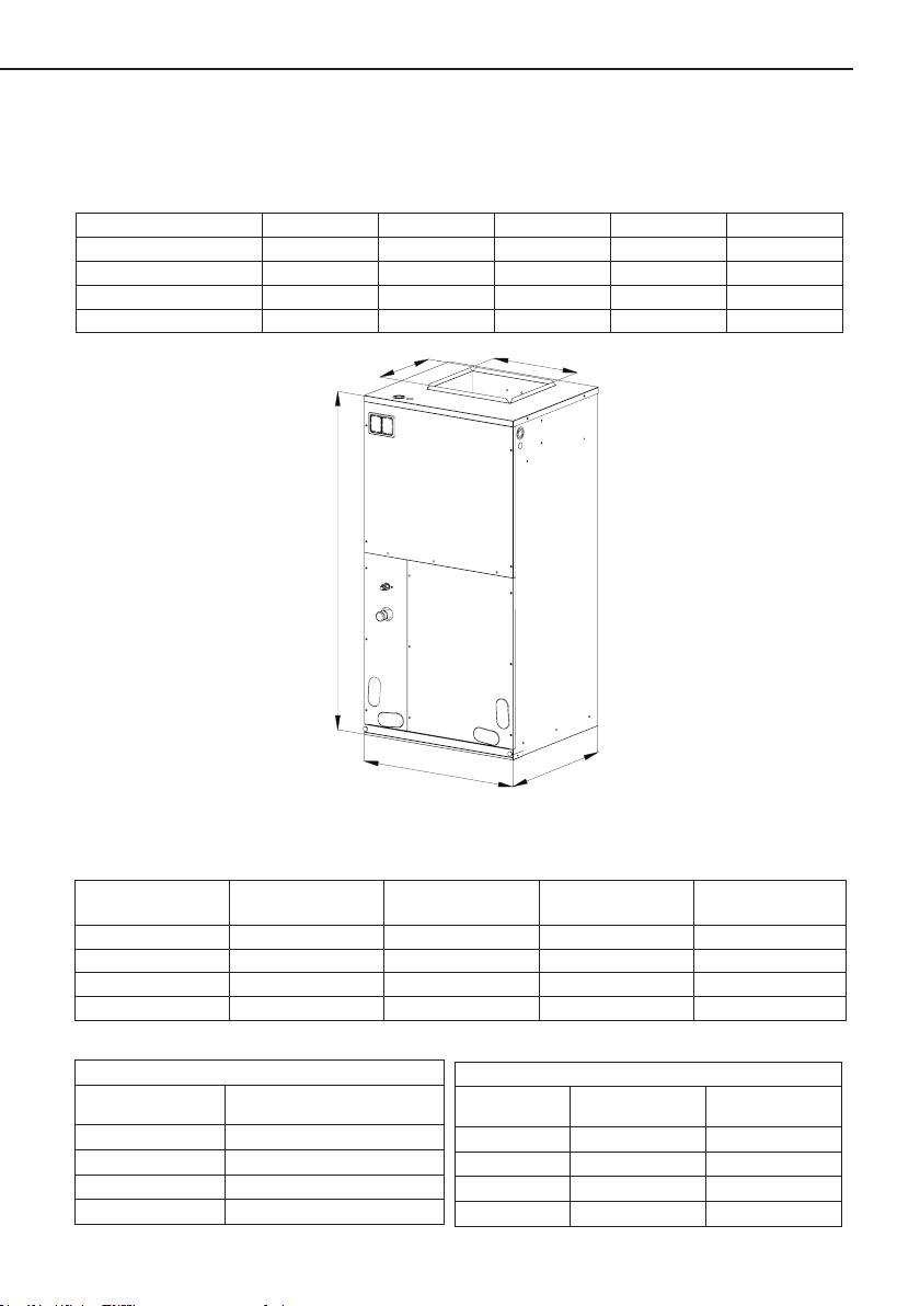
C
E
1. Specications of the Air Handlers
1.1 Physical Dimension
table 1 Unit: Inch
Model A B C D E
VAF-24A308I 21" 21-5/16" 10-3/4" 11-5/16" 43-1/2"
VAF-36A308I 21" 21-5/16" 12-1/4" 11-5/16" 48-3/16"
VAF-42A308I 24-1/2" 21-5/16" 13-3/4" 11-1/2" 48-3/16"
VAF-55A308I 24-1/2" 21-5/16" 13-3/4" 11-1/2" 48-3/16"
D
1.2 General Information
Model Cooling capacity Blower (inch)
VAF-24A308I
VAF-36A308I
VAF-42A308I
VAF-55A308I
Model Filter size (inch)
VAF-24A308I
VAF-36A308I
VAF-42A308I
VAF-55A308I
table 3 table 4
2.0 Ton 9.5×8 706 0-10
3.0 Ton 10×10 1150 0-20
3.5 Ton 11×11 1300 0-20
4.5 Ton 11×11 1420 0-20
Filters
19-5/16"X21-1/8"X1"
19-5/16"X21-1/8"X1"
20-5/16"X23"X1"
20-5/16"X23"X1"
A
Figure 1
table 2
VAF-24A308I 126/135lb. 154
VAF-36A308I 139/152lb. 112
VAF-42A308I 163/178lb. 81
VAF-55A308I 163/178lb. 81
B
Nominal SCFM
Model Net Wt/Gross Wt
Shipping Data
1
Electric heat(kw)
Loading QTY(40’
Container)
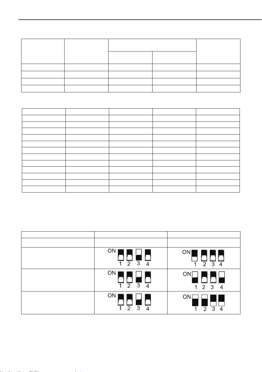
table 5
Air Handler
Motor @ 230V 1Ph 60Hz
HP FLA
DD Blower Wheel
(inch)
Model
VAF-24A308I
VAF-36A308I
VAF-42A308I
VAF-55A308I
Airow Tonnage
Range
2.0 1/17 0.52 9.5×8
3.0 1/2 3.6 10×10
3.5 3/4 4.6 11×11
4.5 3/4 4.6 11×11
The air ow of indoor unit
table 6
Model VAF-24A308I VAF-36A308I VAF-42A308I VAF-55A308I
ESP(in.wg) Air volume(CFM) Air volume(CFM) Air volume(CFM) Air volume(CFM)
0 808.4 1287.9 1377.4 1504.5
0.04 776.2 1250.8 1367.8 1483.8
0.08 742.1 1218.0 1339.6 1462.7
0.12 706.8 1181.2 1326.8 1441.6
0.16 666.6 1147 1300.4 1420.5
0.2 623.4 1113.1 1288.6 1400.6
0.24 576.4 1083.0 1271.4 1379.4
0.28 514.1 1055.8 1242.8 1357.8
0.32 452.3 1014.8 1214.3 1335.3
0.36 384.2 963.1 1208.1 1312.1
0.4 306.4 906.5 1182.5 1288.5
Notes:
Based upon W/nominal tonnage, dry coil and lter should be installed.
①
Use 0.96 as approximate CFM correction factor for wet coil.
②
See the following table for how to set the DIP switch of the unit VAF-36A308I and VAF-42A308I:
table 7
Model/DIP Switch COOL HEAT
VAF-24A308I
/ /
VAF-36A308I
VAF-42A308I
VAF-55A308I
Note: The black part presents the switch rod.
2
Air Handler
2. Pre-Installation Instruction
2.1 Checking Product Received
After receiving the product, please check if there is any damage caused by transportation.
Shipping damage is the responsibility of the carrier. Verify the model number, specications and
accessories are correct prior to installation. The distributor or manufacturer will not accept claims
from dealers for transportation damage or installation of incorrectly shipped units.
2.2 Before Beginning Installation
Carefully read all instructions for the installation prior to installing product. Make sure each step
or procedure is understood and any special considerations are taken into account before starting
installation. Assemble all tools, hardware and supplies needed to complete the installation. Some
items may need to be purchased locally. Make sure everything needed to install the product is on
hand before starting.
2.3 Codes & Regulations
DANGER
IMMEDIATE HAZARDS WHICH WILL RESULT IN PROPERTY DAMAGE, PRODUCT
DAMAGE, SEVERE PERSONAL INJURY OR DEATH.
WARNING
HAZARDS OR UNSAFE PRATICES COULD RESULT IN PROPERTY DAMAGE, PRODUCT
DAMAGE, SEVERE PERSONAL INJURY OR DEATH.
CAUTION
HAZARDS OR UNSAFE PRACTICES WHICH MAY RESULT IN PROPERTY DAMAGE,
PRODUCT DAMAGE, SEVERE PERSONAL INJURY OR DEATH.
WARNING
BEFORE SERVING OR INSTALLING THIS EQUIPMENT.THE ELECTRICAL POWER TO
THIS UNIT MUST BE IN THE “OFF” POSITION. CAUTION, MORE THAN ONE DISCONNECT
MAY EXIST. FAILURE TO OBSERVE THIS WARNING MAY RESULT IN AN ELECTRICAL SHOCK
THAT CAN CAUSE PERSONAL INJURY OR DEATH .
WARNING
THE UNITED STATES ENVIRONMENTAL PROTECTION AGENCY (‘EPA”) HAS
ISSUED VARIOUS REGULATIONS REGARDING THE INTRODUCTION AND DISPOSAL
OF REFRIGERANTS INTRODUCED INTO THIS UNIT. FAILURE TO FOLLOW THESE
REGULATIONS MAY HARM THE ENVIROMENT AND CAN LEAD TO THE IMPOSITION OF
SUBSTANTIAL FINES. THESE REGULATIONS MAY VARY DUE TO THE PASSAGE OF LAWS.
A CERTIFIED TECHNICIAN MUST PERFORM THE INSTALLATION AND SERVICE OF THIS
PRODUCT. SHOULD QUESTIONS ARISE, CONTACT YOUR LOCAL EPA OFFICE.
3
 Loading...