


Rcvr-Acct#:
PRU - 7777
Date:
June 25, 2007 09:53 AM
Name:
COMPANY NAME & ADDRESS:
CONTACT:
PHONE:
FAX:
NOTES:
DATE ENTERED:
DATE MODIFIED:
LEONEL PRUEBAS
Business:
CUSTOMER INFORMATION
LEONEL PRUEBAS
06/25/2007 09:45 A
06/25/2007 09:45 A
USER_DEFINED_FIELD1:
USER_DEFINED_FIELD2:

Rcvr-Acct#:
PRU - 7777
Date:
June 25, 2007 09:53 AM
Name:
LEONEL PRUEBAS
Business:
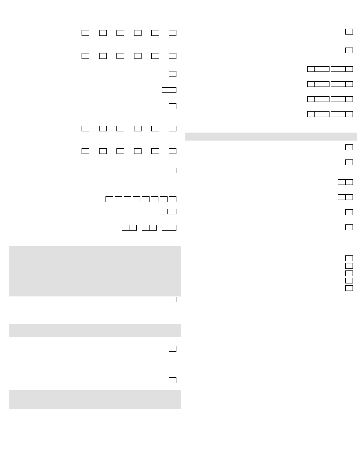
Vista250FBP-1 PROGRAMMING FORM
Some fields are programmed for each partition (shown as shaded fields). See the PARTITION-SPECIFIC section for
programming these fields. Standard default (*97) values are shown in brackets [ ], otherwise default = 0.
*00
*04
*05
*06
*08
*09
*10
*11
*12
*13
*14
*15
*16
INSTALLER CODE
RANDOM TIMERS
Partition-Specific
SYSTEM EVENT NOTIFY
[0 = No]; 1 = Yes
QUICK EXIT
Partition-Specific
TEMPORAL SIREN PULSE
[0 = fire sounds on 1 sec., off 1 sec.];
1 = fire sounds temporal pulse
ENTRY DELAY #1
EXIT DELAY #1
ENTRY DELAY #2
EXIT DELAY #2
BELL 1 TIMEOUT
Partition-Specific
Partition-Specific
Partition-Specific
Partition-Specific
Partition-Specific
TRIGGER OR RS232 INPUT
[0 = Trigger]; 1 = RS232
KEYSWITCH ASSIGNMENT
[0 = no keyswitch]; 1-8 = partition in which keyswitch used;
9 = Silences bells if fire alarm present;
BELL 1 CONFIRMATION
Partition-Specific
OF ARMING DING
5 1 4 0
*33
0
*34
0
*35
*36
*37
0
0
*38
*39
PRIMARY PHONE NUMBER
[ ] Enter 0-9 for each digit
Enter #11 for *, #12 for #, #13 for 2 second pause.
SECONDARY PHONE NUMBER
[ ] Enter 0-9 for each digit
Enter #11 for *, #12 for #, #13 for 2 second pause.
DOWNLOAD PHONE No.
[ ] Enter 0-9 for each digit
Enter #11 for *, #12 for #, #13 for 2 second pause.
DOWNLOAD ID No.
* * * * * * * * * * * * * * * *
Enter 00-09; A-F (10-15) [15 15 15 15 15 15 15 15]
DOWNLOAD COMMAND ENABLES
1 1 0
Dialer
Shutdown
See 1*53 for Callback disable option. 0=Disable; [1=Enable]
For UL installations, All options must be disabled.
System
Shutdown
1 1 1 1 1
Not
Used
Remote
Bypass
Remote
Disarm
Remote
Arm
PREVENT ZONE XXX BYPASS
ENABLE OPEN/CLOSE REPORT
FOR INSTALLER CODE
Upload
Program
Partition-Specific
Partition-Specific
Download
Program
*17
*19
*20
*22
*23
*24
*25
*26
*27
*28
*29
AC LOSS KEYPAD SOUNDING
[0 = no sounding]; 1 = AC loss keypad sounding
RANDOMIZE AC LOSS REPORT
0 = Send report at loss;
1 = randomize report transmission 10-40 min.;
[2 = randomize 6-12 hours];
TELEPHONE MODULE PHONE CODE
Enter 01-09 for 1st digit; 11 (for *) or 12 (for #) for 2nd digit.
[00, 11] Must be 00, 00 for Commercial Fire & UL Commercial Burg.
installations.
KEYPAD PANIC ENABLES
MULTIPLE ALARMS
0 0 1 1
Partition-Specific
Partition-Specific
IGNORE EXPANSION ZONE TAMPER
[0=Enable tamper for RF and RPMs]; 1=Ignore
Must be "0" for UL if these devices are used.
LRR BURGLARY TRIGGER
FOR ZONE RESPONSE TYPE 8
0 = no type 8 trigger; [1 = J2 pin 3 triggers on type 8 alarm]
INTELLIGENT TEST REPORTING
[0 = test report always sent];
1 = No report sent if any other report was recently sent; Set "0" UL
TEST REPORT INTERVAL
Enter interval in hours, 0001-9999; 0000=No report [0024];
Max. 0024 for Commercial Fire & UL.
0 0 2 4
POWER UP IN PREVIOUS STATE
0 = power up disarmed;
[1 = power up in previous state]; "1" for UL
QUICK ARM
Partition-Specific
0
*40
2
*41
*42
*43
*44
*45
0
*46
1
*47
0
*48
*49
*50
1
*51
OPEN/CLOSE REPORT FOR KEYSWITCH
[0 = no report]; 1 = send open/close keyswitch report
NORMALLY CLOSED or EOLR (Zone 2-8)
[0=EOLR supervision]; 1=N.C. Loops Must be "0" for UL.
DIAL TONE PAUSE
[0=5 seconds]; 1=11 seconds; 2=30 seconds;
Must be "0" for UL.
DIAL TONE DETECTION
0=pause, then dial; [1=wait for dial tone]
RING DETECTION COUNT
[00=no detection]; 01-14 rings; 15=answering machine;
PRIMARY FORMAT
0= Low Speed; [1=Contact ID]; 2=ADEMCO High Speed;
3=ADEMCO Express
LOW SPEED FORMAT (Primary)
[0=ADEMCO Low Speed]; 1=Sescoa/Radionics
SECONDARY FORMAT
0= Low Speed; [1=Contact ID]; 2=ADEMCO High Speed;
3=ADEMCO Express
LOW SPEED FORMAT (Secondary)
[0=Ademco Low Speed]; 1=Sescoa/Radionics
CHECKSUM VERIFICATION
[0=No]; 1=Yes Primary Scndry
[0] [0]
0 0
SESCOA/RADIONICS SELECT
[0=Radionics]; 1=Sescoa
DUAL REPORTING
[0 = No dual reporting]; 1 = dual reporting. See Installation
Instructions if used with Split Reporting "1" option (1*34).
0
0
0
1
1 0
1
0
1
0
0
0
*30
*31
*32
MAIN DIALER TOUCHTONE
[0=Rotary]; 1=Touchtone
PABX ACCESS CODE
[ ] 0-9; B-F (11-15)
PRIM. SBSCRBR ACCT#
0
Partition-Specific
-1-
Vista250FBP-1
Rcvr-Acct#:
PRU - 7777
Date:
June 25, 2007 09:53 AM
Name:
*52
*53
*54
*56
*57
*58
*59
*77
*79
*80
*83
*84
*85
*87
*88
LEONEL PRUEBAS
STANDARD/EXPANDED REPORT
FOR PRIMARY
[0 = Standard]; Alarm
1 = Expanded; Note: Expanded overrides choices in 4+2 format.
STANDARD/EXPANDED REPORT
FOR SECONDARY
[0 = Standard]; Alarm
1 = Expanded; Note: Expanded overrides choices in 4+2 format.
UNATTENDED MODE
0 = Disable; [1 = Enable, if automatic downloads will be allowed.]
DYNAMIC SIGNALING DELAY
[0 = No Time Delay
Enter (0 to 15) * 15 seconds delay based on report priority
DYNAMIC SIGNALING PRIORITY
[0 = Telephone]; 1 = Long Range Radio;
Select Reporting method to try first.
LONG RANGE RADIO CS#1 CATEGORY ENABLE
[0 = Disable];
1 = Enable
LONG RANGE RADIO CS#2 CATEGORY ENABLE
[0 = Disable];
1 = Enable
AUTO TROUBLE RESTORE
[0 = Disabled];
1 = Allows the automatic restoral of trouble and supervisory
conditions when the zone is returned to a "ready"
condition (entry of code + off is not required).
ZONE TYPE RESTORE ENABLES
FOR ZONE TYPES 1-8
[0 = Disable]; 1 = Enable
ZONE TYPE RESTORE ENABLES
FOR ZONE TYPES 9-10
[0 = Disable]; 1 = Enable
FIRST TEST REPORT TIME
[Day = 00; Hour = 12; Min = 00];
Days 01-07; Hours 00-23; Minutes 00-59;
00 in all boxes = instant. Day 01 = Monday
SWINGER SUPPRESSION
ENABLE DIALER REPORTS
FOR PANICS & DURESS
ENTRY WARNING
BURGLARY ALARM
COMMUNICATION DELAY
0 0 0 0 0 0
Restore
Bypass Trouble
0 0 0 0 0 0
Restore
Bypass Trouble
0 0 0 0 0 0
Alarm Trouble Bypass
0 0 0 0 0 0
Alarm Trouble Bypass
0 0 0 0 0 0 0 0
1 2 3 4 5 6 7 8
0 0 1 2 0 0
Opn/Cls
Opn/Cls
Opn/Cls
System Test
Opn/Cls
System Test
Partition Specific
Partition Specific
Partition Specific
Partition Specific
Partition Specific
Low Batt
Low Batt
0 0
0 0
9 10
Business:
1*20
1*21
1*22
1
1*23
1*24
0
1*25
1*26
1*28
1*29
0
1*30
1*31
1*33
1*34
1*35
AUTOBYPASS FAULTED EXIT ROUTE ZONES
0 = No;
[1 = Bypass Entry/Exit and Interior zone faulted after exit delay]
Must be "0" for UL Commercial Burglary.
EXIT DELAY RESET
0 = No;
[1 = Resets Exit Delay to "60 seconds" after zone is closed.]
Must be "0" for UL Commercial Burglary.
CROSS-ZONING PAIR 1
[000,000] Enter 3-digit zone numbers to be linked so that both
must fault within a five minute period to cause an alarm.
CROSS-ZONING PAIR 2
[000,000] Enter 3-digit zone numbers to be linked so that both
must fault within a five minute period to cause an alarm.
CROSS-ZONING PAIR 3
[000,000] Enter 3-digit zone numbers to be linked so that both
must fault within a five minute period to cause an alarm.
CROSS-ZONING PAIR 4
[000,000] Enter 3-digit zone numbers to be linked so that both
must fault within a five minute period to cause an alarm.
PANIC BUTTON OR SPEED KEY
RF TRANSMITTER LOW BATTERY SOUND
[0 = When disarmed];
1 = Immediate; Must be "1" for UL.
0 0 0 0 0 0
0 0 0 0 0 0
0 0 0 0 0 0
0 0 0 0 0 0
Partition Specific
RF TRANSMITTER LOW BATTERY
REPORT ENABLE
[0 = Disable];
1 = Enable; Must be "1" for UL.
RF RECEIVER CHECK-IN INTERVAL
[06] 02-15 times 2 hours;
00 = Disables supervision
RF TRANSMITTER CHECK-IN INTERVAL
[12] 02-15 times 2 hours;
00 = Disables transmitter supervision; Max. "02" (4hr) fo UL Fire.
TOUCHTONE WITH ROTARY BACKUP
[0 = Disable];
1 = Enable
COMM. SPLIT REPORT SELECTION
[0 = No];
1 = Alarms and alarm restores primary, others secondary;
2 = Open/close, test secondary, others primary;
See *51 for comments if using with Dual Reporting
ACCESS DIALER ENABLES
TRACE
TROUBLE
BYPASS
SYSTEM
ALARM
1
1
0
0
0 2
0 2
0
0
*89
*90
1*15
1*17
1*18
1*19
RESTORE REPORT TIMING
[0 = Instant Restore];
1 = Report after bell timeout;
2 = Restore report, when system is subsequently disarmed.
Must be "2" for Commercial Fire or UL Commercial Burglary
installation.
SECONDARY SUBSCRIBER
Partition Specific
ACCOUNT NUMBER
CANCEL VERIFY
0 = Disable;
[1 = Enable;]
This causes the system to display "Cancel Alarm" for 90 seconds
and pulse the alarm output three times when is receives a
"kissoff" of a Cancel report from the Central Station.
COMMON LOBBY PARTITION
[0] Enter the "common lobby" partition (1-8)
AFFECTS LOBBY
ARMS LOBBY
Partition Specific
Partition Specific
0
1
0
-2-
Vista250FBP-1

Rcvr-Acct#:
PRU - 7777
Date:
June 25, 2007 09:53 AM
Name:
1*42
1*43
1*44
1*45
1*47
1*48
1*49
1*52
1*53
1*57
1*58
1*60
1*69
1*70
1*71
1*72
1*73
1*74
1*75
1*76
LEONEL PRUEBAS
CALL WAITING DEFEAT
[0 = Do not defeat call waiting];
1 = Defeat call waiting on first attempt.
PERMANENT KEYPAD BACKLIGHT
WIRELESS KEYPAD TAMPER DETECT ENABLE
[0 = No tamper detection];
1 = Lockout RF if tamper detected
EXIT DELAY SOUNDING
CHIME ON BELL/SIREN
WIRELESS KEYPAD ASSIGNMENT
[0 = No Rf keypad];
1-8 = Partition in which RF keypad is used
SUPPRESS TX SUPERVISION SOUND
0 = Transmission trouble sounding;
[1 = Suppress transmission trouble sounding]; Must be "0" for UL.
SEND CANCEL IF ALARM + OFF
DOWNLOAD CALLBACK
[0 = Callback required];
1 = Callback not required; Must be "0" for UL.
5800 RF BUTTON GLOBAL ARM
[0 = No];
1 = Yes
5800 RF BUTTON FORCE ARM
[0 = Disable];
1 = Enable; Must be "0" for UL.
If a zone is faulted after pressing a button,
keypad will beep once. User should press button
again within 4 seconds to force bypass those zones.
ZONE 5 AUDIO ALARM VERIFICATION
[0 = No alarm verification];
1 = Alarm verification used; Must be "0" for UL & Commercial Fire
PRINTER TYPE
[0 = Parallel];
1 = Serial;
EVENT LOG
TYPES
0 = Disable; 1 = Enable
An event log type, enabled by entering "1" here, will be logged
Note:
in the Access Control System if installed.
12/24 HOUR TIME STAMP FORMAT
[0 = 12 hour];
1 = 24 hour
EVENT LOG PRINTER ON-LINE
[0 = Disable];
1 = Enable
PRINTER BAUD RATE
[0 = 1200 baud];
1 = 300 baud
RELAY TIMEOUT XXX MINUTES
[000] Enter the realy timeout (0-127 in multiples of 2 minutes)
desired for #80 Menu mode time driven event relay command
numbers "04/09" and #93 Menu mode relay programming
output command "56".
RELAY TIMEOUT YYY SECONDS
[000] Enter the realy timeout (0-127 seconds) desired for
#80 Menu mode time driven event relay command numbers
"05/10" and #93 Menu mode relay programming output
command "57".
1 0 0 0 1 0
[1] [0] [0] [0] [1] [0]
Alarm Check Bypass Opn/Cls System Test Rpt
ACCESS CONTROL RELAY
FOR PARTITION
Partition Specific
Partition Specific
Partition Specific
Partition Specific
0 0 1
0 0 0
Partition Specific
Business:
0
THIRD PAGE PROGRAMMING FIELDS (press *94)
2*00
2*01
0
2*02
0
2*05
1
2*06
2*07
0
2*08
2*09
0
2*10
0
2*11
0
0
2*18
2*19
2*20
0
2*21
0
0
2*22
2*23
2*24
NUMBER OF PARTITIONS
[1] Enter the number of partitions used in this system
DAYLIGHT SAVINGS TIME
START/END MONTH
[04, 10] Enter 00-12 for Daylight Savings Time Start Month,
and Daylight Savings Time End Month
Enter 00,00 if Daylight Savings Time not used
DAYLIGHT SAVINGS TIME START/END
[1, 5] Enter 1-7 for Daylight Savings Time Start Weekend,
and Daylight Savings Time End Weekend
1 = First; 2 = Second; 3 = Third; 4 = Fourth; 5 = Last;
6 = Next to Last; 7 = Third from Last.
Example: 1,5 = First Sunday in April, Last Sunday in October
AUTO-ARM DELAY
AUTO-ARM WARNING PERIOD
AUTO-DISARM DELAY
ENABLE FORCE ARM
FOR AUTO-ARM
OPEN/CLOSE REPORTS
BY EXCEPTION
ALLOW DISARMING ONLY DURING
ARMING/DISARMING WINDOWS
ALLOW DISARM OUTSIDE WINDOW
IF ALARM OCCURS
[0 = Disarming can only be done during the disarm window];
1 = System can be disarmed outside the disarm window if
an alarm has occurred.
Used only if field 2*10 (partition specific field) is set to "1".
If field 2*10 is set to "0" for a partition, this field (2*11)
has no effect for that partition.
ENABLE GO TO
FOR THIS PARTITION
USE PARTITION DESCRIPTORS
[0 = use non-partition type descriptors];
1 = use partition descriptors
ENABLE J2 TRIGGERS
FOR THIS PARTITION
ENABLE SUPERVISION PULSES
FOR LRR TRIGGER OUTPUTS
[00000] Used for supervised connection to a transmitter.
Enter "0" to disable or "1" to enable the listed outputs.
F = Fire; B = Burglary; P = Silent panic/duress; S = Supervision;
T = Trouble.
DISPLAY FIRE ALARMS
OF OTHER PARTITIONS
DISPLAY BURGLARY & PANIC
ALARMS OF OTHER PARTITIONS
DISPLAY TROUBLES
OF OTHER PARTITIONS
1
0 4 1 0
Start End
1 5
Start | End
Partition Specific
Partition Specific
Partition Specific
Partition Specific
Partition Specific
Partition Specific
0
Partition Specific
0
Partition Specific
0 0 0 0 0
F B P S T
Partition Specific
Partition Specific
Partition Specific
1*77
LOG FIRST MAINTENANCE SIGNAL
[0 = No log];
1 = Log first maintenance signal
0
-3-
Vista250FBP-1
Rcvr-Acct#:
PRU - 7777
Date:
June 25, 2007 09:53 AM
Name:
2*30
2*31
PAGER INSTALLED
[0] 0 = No; 1 = Yes
DELAY PAGING
LEONEL PRUEBAS
Business:
0
0
P1
[0] Enter 1 to enable sending the message to the pager after
it is sent via the dialer.
2*32
PAGER OPTIONS
TIME TO DELAY PAGING AFTER DIALER
[0] Enter the time to delay sending message to the pager.
00-24 times 10 sec.
ID Phone ID
Number
1 0 0 0 0 0 0 0 0 0
2 0 0 0 0 0 0 0 0 0
3 0 0 0 0 0 0 0 0 0
4 0 0 0 0 0 0 0 0 0
5 0 0 0 0 0 0 0 0 0
6 0 0 0 0 0 0 0 0 0
7 0 0 0 0 0 0 0 0 0
8 0 0 0 0 0 0 0 0 0
PAGER PHONE NUMBER
[ ] Enter 0-9 for each digit. Enter #11 for "*"; #12 for "#"; #13 for 2 sec pause.
PAGER ID NUMBER
[ ] Enter the pager ID number. Up to 10 digits. Press "*" after the last digit if less than 10 is required.
PAGER FORMAT
[0] 0 = DTMF; 1 = ID; 2 = Alphanumeric
PAGER DELAY 1
[0] Enter the delay time 00-60 sec. The delay occurs between the phone number and the pager ID.
PAGER DELAY 2
[0] Enter the delay time 00-60 sec. The delay occurs between the pager ID and the event information.
PAGER PARTITION ENABLE
[0] 0 = Disable; 1 = Enable
PAGER TRIGGER EVENT ENABLE
[0] 0 = Disable; 1 = Enable
Number
Format
Delay Delay Prtn1 Alarm Trouble Bypass Open/ System Test
1 2 Enbl Close
00
-3A-
Vista250FBP-1

Rcvr-Acct#:
PRU - 7777
Date:
June 25, 2007 09:53 AM
Name:
3*00
3*01
3*12
3*13
3*14
3*15
3*16
LEONEL PRUEBAS
CHECK OR TROUBLE DISPLAY
[0 = Check Displayed];
1 = Trouble Displayed
FIRE DISPLAY LOCK
[0 = scroll all alarms];
1 = lock display of first fire alarm (press "*" to display other alarms)
ZONE TYPE 18 DELAY USE
0 = no delay for zone type 18;
[1 = use delay in 3*16 for zone type 18]
FOR UL,
cannot exceed 90 seconds.
SUPERVISORY ON OPEN AND SHORT
[0 = supv. on short/trouble on open];
1 = supv. on short or open
WATERFLOW SILENCE OPTION
[0 = Silence on Code + OFF];
1 = Silence when waterflow restores.
This feature may only be set to "1" by permission
of the local authority.
ALARM SOUNDS BELL 1,2
0 = Pulsed; 1 = Steady
ZONE TYPES 17/18 DELAY
[00] (Waterflow & Fire Supv) Enter 00-15 times 2 seconds
combined initiating device delay plus this field's value
[1,0]
1 0
Bell 1 Bell 2
0 0
Business:
3*50
0
0
3*55
1
3*56
3*57
0
3*59
3*60
0
3*61
3*82
ZONE TYPE 16-18 RESTORE
[0 = No restore];
1 = send restore; Must be "1" for Commercial Fire
& UL Commercial Burglary installations
0 0 0
16 17 18
RESET BELL 1 AFTER SECOND OFF
[0 = No reset]
1 = Reset Bell 1 after two off sequences
RESET BELL 2 AFTER SECOND OFF
[0 = No reset]
1 = Reset Bell 2 after two off sequences
CONFRIM ARM BELL 2, AUX
CHIME ON BELL 2, AUX
BELL 2 & AUX. RELAY TIMEOUT
Partition-Specific
Partition-Specific
Partition-Specific
AUX. RELAY FUNCTION SELECT
0 = Trouble/Supervisory;
[1 = Alarm, silenced by code + OFF]
2 = Smoke Detector Reset;
3 = Battery Save;
4 = Alarm, silenced by code + "#" + 67
BURGLARY FEATURES ENABLED
0 = disable AWAY, STAY, MAX, TEST, INSTANT & CHIME
functions in partition 1
[1 = enable burglary functions in partition 1]
0
0
1
1
3*17
3*18
3*19
3*20
3*21
3*30
3*31
ZONE 6 ALTERNATE FUNCTION
ZONE 6 ALTERNATE FUNCTION
[0 = zone 6 used]; 1 = zone 6 is tamper zone
EXTENDED DELAY FOR TYPES 17 & 18
[0 = use delay in 3*16];
1 = multiply 3*16 delay by 4
AUX IN ALTERNATE FUNCTION
[0 = pins 5&9 function as per 3*20];
1 = pins 5&9 act as printer RXD & DTR
TRIGGER OUTPUTS SELECTION
[0 = LORRA full connection & Remote Console Sounder];
1 = LORRA limited connection & Keyswitch LEDs;
2 = LORRA fire only connection & 5140LED
MAXIMUM NUMBER OF DIALER ATTEMPTS
1-[8] (3, 4 or 5 for NFPA71 compliant systems when a
secondary phone number is programmed (field *34))
DIALER SELECTION
0 = No dialer; 1 = Use dialer
[1,0]
1 0
Main Backup
BACKUP TOUCHTONE
[0 = Rotary]; 1 = TouchTone
0
3*85
0
0
0
8
0
SYSTEM ZONE BYPASS INHIBIT
0 = prevent bypass of system and fire zones;
[1 = only installer can bypass];
2 = only installer & master user can bypass. Applies to
fire zone types 9, 16, 17 & 18 and system zones 970-977.
in Partition 1
1
-4-
Vista250FBP-1
Rcvr-Acct#:
PRU - 7777
Date:
June 25, 2007 09:53 AM
Name:
LEONEL PRUEBAS
Business:
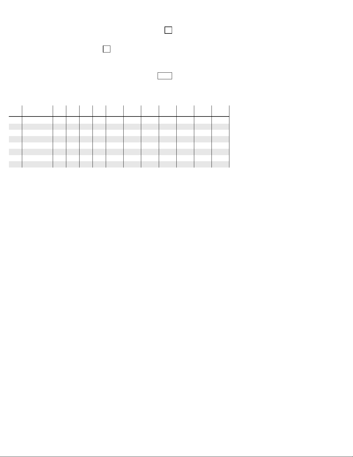
ASSIGN RESPONSE TYPE FOR ZONES 1-250 Standard default values are shown in brackets [ ], otherwise default = 0.
0 9
0 9
0 3
0 4
0 3
0 3
0 3
0 3
[9]
[9]
[3]
[4]
[3]
[3]
[3]
[3]
10
11
12
13
14
15
16
9
0 0
0 0
0 0
0 0
0 0
0 0
0 0
0 0
17
18
19
20
21
22
23
24
0 0
0 0
0 0
0 0
0 0
0 0
0 0
0 0
25
26
27
28
29
30
31
32
0 0
0 0
0 0
0 0
0 0
0 0
0 0
0 0
33
34
35
36
37
38
39
40
0 0
0 0
0 0
0 0
0 0
0 0
0 0
0 0
41
42
43
44
45
46
47
48
0 0
0 0
0 0
0 0
0 0
0 0
0 0
0 0
49
50
51
52
53
54
55
56
0 0
0 0
0 0
0 0
0 0
0 0
0 0
0 0
57
58
59
60
61
62
63
64
0 0
0 0
0 0
0 0
0 0
0 0
0 0
0 0
65
66
67
68
69
70
71
72
0 0
0 0
0 0
0 0
0 0
0 0
0 0
0 0
73
74
75
76
77
78
79
80
0 0
0 0
0 0
0 0
0 0
0 0
0 0
0 0
81
82
83
84
85
86
87
88
1
2
3
4
5
6
7
8
RESPONSE TYPES FOR ZONES 89-176
89
90
91
92
93
94
95
96
0 0
0 0
0 0
0 0
0 0
0 0
0 0
0 0
97
98
99
100
101
102
103
104
0 0
0 0
0 0
0 0
0 0
0 0
0 0
0 0
105
106
107
108
109
110
111
112
0 0
0 0
0 0
0 0
0 0
0 0
0 0
0 0
113
114
115
116
117
118
119
120
0 0
0 0
0 0
0 0
0 0
0 0
0 0
0 0
121
122
123
124
125
126
127
128
0 0
0 0
0 0
0 0
0 0
0 0
0 0
0 0
129
130
131
132
133
134
135
136
0 0
0 0
0 0
0 0
0 0
0 0
0 0
0 0
137
138
139
140
141
142
143
144
0 0
0 0
0 0
0 0
0 0
0 0
0 0
0 0
145
146
147
148
149
150
151
152
0 0
0 0
0 0
0 0
0 0
0 0
0 0
0 0
153
154
155
156
157
158
159
160
0 0
0 0
0 0
0 0
0 0
0 0
0 0
0 0
161
162
163
164
165
166
167
168
0 0
0 0
0 0
0 0
0 0
0 0
0 0
0 0
169
170
171
172
173
174
175
176
0 0
0 0
0 0
0 0
0 0
0 0
0 0
0 0
0 0
0 0
0 0
0 0
0 0
0 0
0 0
0 0
RESPONSE TYPES FOR ZONES 177-250
177
178
179
180
181
182
183
184
0 0
0 0
0 0
0 0
0 0
0 0
0 0
0 0
185
186
187
188
189
190
191
192
0 0
0 0
0 0
0 0
0 0
0 0
0 0
0 0
193
194
195
196
197
198
199
200
0 0
0 0
0 0
0 0
0 0
0 0
0 0
0 0
201
202
203
204
205
206
207
208
0 0
0 0
0 0
0 0
0 0
0 0
0 0
0 0
RESPONSE TYPES FOR RELAYS 1-32
601
602
603
604
605
606
607
608
0 0
0 0
0 0
0 0
0 0
0 0
0 0
0 0
609
610
611
612
613
614
615
616
0 0
0 0
0 0
0 0
0 0
0 0
0 0
0 0
617
618
619
620
621
622
623
624
0 0
0 0
0 0
0 0
0 0
0 0
0 0
0 0
625
626
627
628
629
630
631
632
209
210
211
212
213
214
215
216
0 0
0 0
0 0
0 0
0 0
0 0
0 0
0 0
0 0
0 0
0 0
0 0
0 0
0 0
0 0
0 0
217
218
219
220
221
222
223
224
0 0
0 0
0 0
0 0
0 0
0 0
0 0
0 0
225
226
227
228
229
230
231
232
0 0
0 0
0 0
0 0
0 0
0 0
0 0
0 0
233
234
235
236
237
238
239
240
0 0
0 0
0 0
0 0
0 0
0 0
0 0
0 0
241
242
243
244
245
246
247
248
0 0
0 0
0 0
0 0
0 0
0 0
0 0
0 0
249
250
0 0
0 0
RESPONSE TYPES FOR ECP ADDRESSES 0-30
800
801
802
803
804
805
806
807
0 0
0 0
0 0
0 0
0 0
0 0
0 0
0 0
808
809
810
811
812
813
814
815
0 0
0 0
0 0
0 0
0 0
0 0
0 0
0 0
816
817
818
819
820
821
822
823
0 0
0 0
0 0
0 0
0 0
0 0
0 0
0 0
824
825
826
827
828
829
830
0 0
0 0
0 0
0 0
0 0
0 0
0 0
SYSTEM / FIRE ZONES
970
971
972
973
0 0
1 9
1 9
1 9
[19]
[19]
[19]
974
975
976
977
1 9
0 0
0 0
0 0
[19]
988
990
992
995
0 0
0 0
N A
0 9
[9]
996
997
999
0 8
1 9
0 6
[8]
[19]
[6]
RESPONSE TYPES: 0 - Disabled
1 - Entry/Exit 1 2 - Entry/Exit 2
3 - Perimeter 4 - Interior Follower
5 - Trouble Day/Alarm Night 6 - 24 Hour Silent
7 - 24 Hour Audible 8 - 24 Hour Auxiliary
9 - Fire Without Verification 10 - Interior w/Delay
14 - PLM Supervision 16 - Fire With Verification
17 - Fire Waterflow 18 - Fire Supervisory
19 - 24 Hour Trouble 20 - Arming-Stay
21 - Arming-Away 22 - Disarming
23 - No Alarm 27 - Access Point
28 - MLB Supervision 29 - Momentary Exit
-5-
Vista250FBP-1
Rcvr-Acct#:
PRU - 7777
Date:
June 25, 2007 09:53 AM
Name:
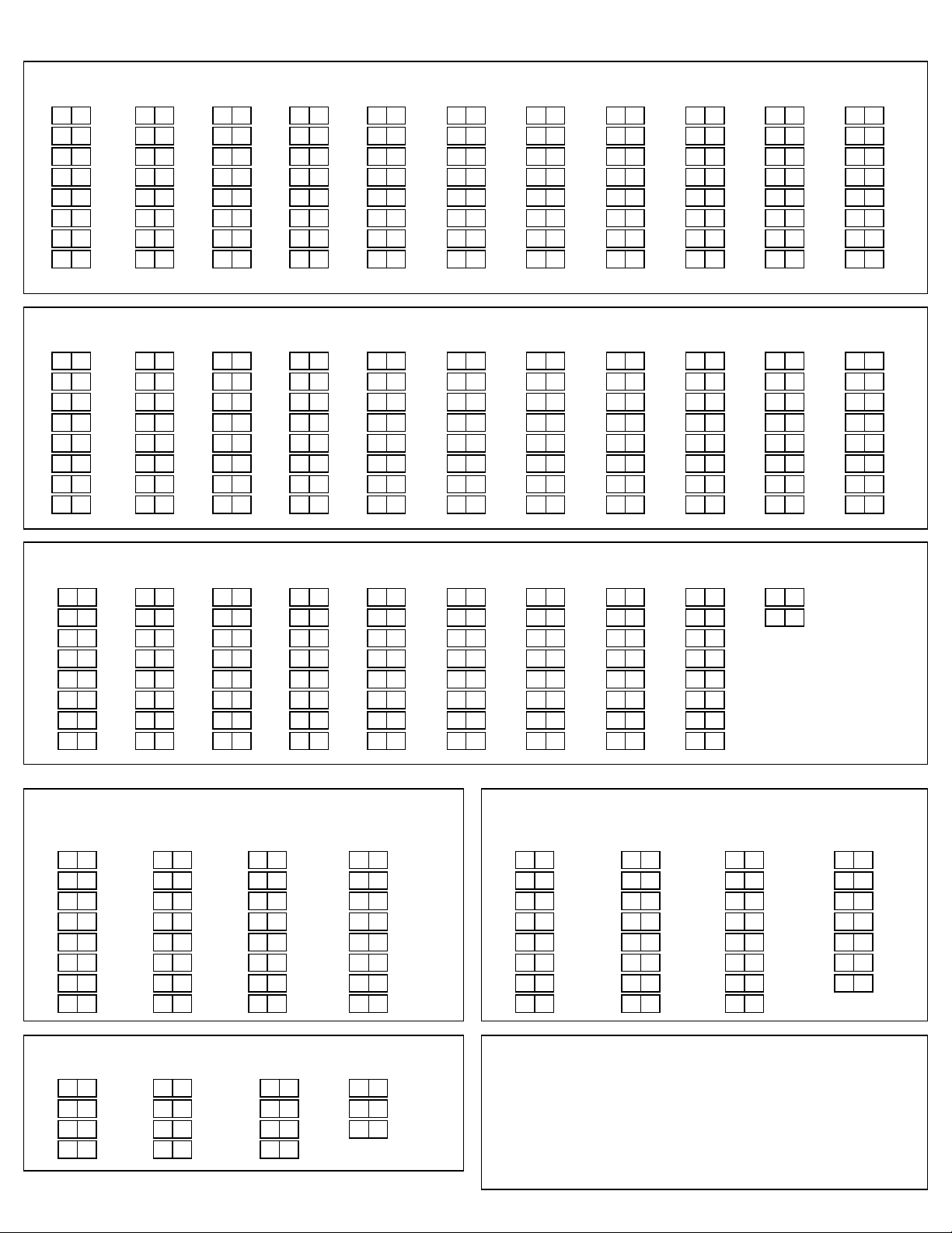
ALARM REPORT CODE & ID DIGITS FOR ZONES 1-32 & SUPERVISORY & RESTORE CODES
[All codes default to 00]
Code
0 1 0 0
1
0 1 0 0
2
0 1 0 0
3
0 1 0 0
4
0 1 0 0
5
0 1 0 0
6
0 1 0 0
7
0 1 0 0
8
ALARM REPORT CODE & ID DIGITS FOR ZONES 33-64 & SUPERVISORY & RESTORE CODES
[All codes default to 00]
Code
0 1 0 0
33
0 1 0 0
34
0 1 0 0
35
0 1 0 0
36
0 1 0 0
37
0 1 0 0
38
0 1 0 0
39
0 1 0 0
40
ALARM REPORT CODE & ID DIGITS FOR ZONES 65-96
[All codes default to 00]
Code
0 1 0 0
65
0 1 0 0
66
0 1 0 0
67
0 1 0 0
68
0 1 0 0
69
0 1 0 0
70
0 1 0 0
71
0 1 0 0
72
ID
ID
ID
LEONEL PRUEBAS
Code
0 1 0 0
9
0 1 0 0
10
0 1 0 0
11
0 1 0 0
12
0 1 0 0
13
0 1 0 0
14
0 1 0 0
15
0 1 0 0
16
Code
0 1 0 0
41
0 1 0 0
42
0 1 0 0
43
0 1 0 0
44
0 1 0 0
45
0 1 0 0
46
0 1 0 0
47
0 1 0 0
48
Code
0 1 0 0
73
0 1 0 0
74
0 1 0 0
75
0 1 0 0
76
0 1 0 0
77
0 1 0 0
78
0 1 0 0
79
0 1 0 0
80
ID
ID
ID
0 0
0 0
0 0
0 0
0 0
0 0
0 0
0 0
0 0
0 0
0 0
0 0
0 0
0 0
0 0
Alarm Rst.
Trouble
Trouble Rst.
Bypass
Bypass Rst.
Alarm Rst.
Trouble
Trouble Rst.
Bypass
Bypass Rst.
Alarm Rst.
Trouble
Trouble Rst.
Bypass
Bypass Rst.
Code
0 1 0 0
17
0 1 0 0
18
0 1 0 0
19
0 1 0 0
20
0 1 0 0
21
0 1 0 0
22
0 1 0 0
23
0 1 0 0
24
Code
0 1 0 0
49
0 1 0 0
50
0 1 0 0
51
0 1 0 0
52
0 1 0 0
53
0 1 0 0
54
0 1 0 0
55
0 1 0 0
56
Code
0 1 0 0
81
0 1 0 0
82
0 1 0 0
83
0 1 0 0
84
0 1 0 0
85
0 1 0 0
86
0 1 0 0
87
0 1 0 0
88
Business:
ID
ID
ID
Code
0 1 0 0
25
0 1 0 0
26
0 1 0 0
27
0 1 0 0
28
0 1 0 0
29
0 1 0 0
30
0 1 0 0
31
0 1 0 0
32
Code
0 1 0 0
57
0 1 0 0
58
0 1 0 0
59
0 1 0 0
60
0 1 0 0
61
0 1 0 0
62
0 1 0 0
63
0 1 0 0
64
Code
0 1 0 0
89
0 1 0 0
90
0 1 0 0
91
0 1 0 0
92
0 1 0 0
93
0 1 0 0
94
0 1 0 0
95
0 1 0 0
96
ID
ID
ID
0 0
0 0
0 0
0 0
0 0
0 0
0 0
0 0
0 0
0 0
0 0
0 0
0 0
0 0
0 0
Alarm Rst.
Trouble
Trouble Rst.
Bypass
Bypass Rst.
Alarm Rst.
Trouble
Trouble Rst.
Bypass
Bypass Rst.
Alarm Rst.
Trouble
Trouble Rst.
Bypass
Bypass Rst.
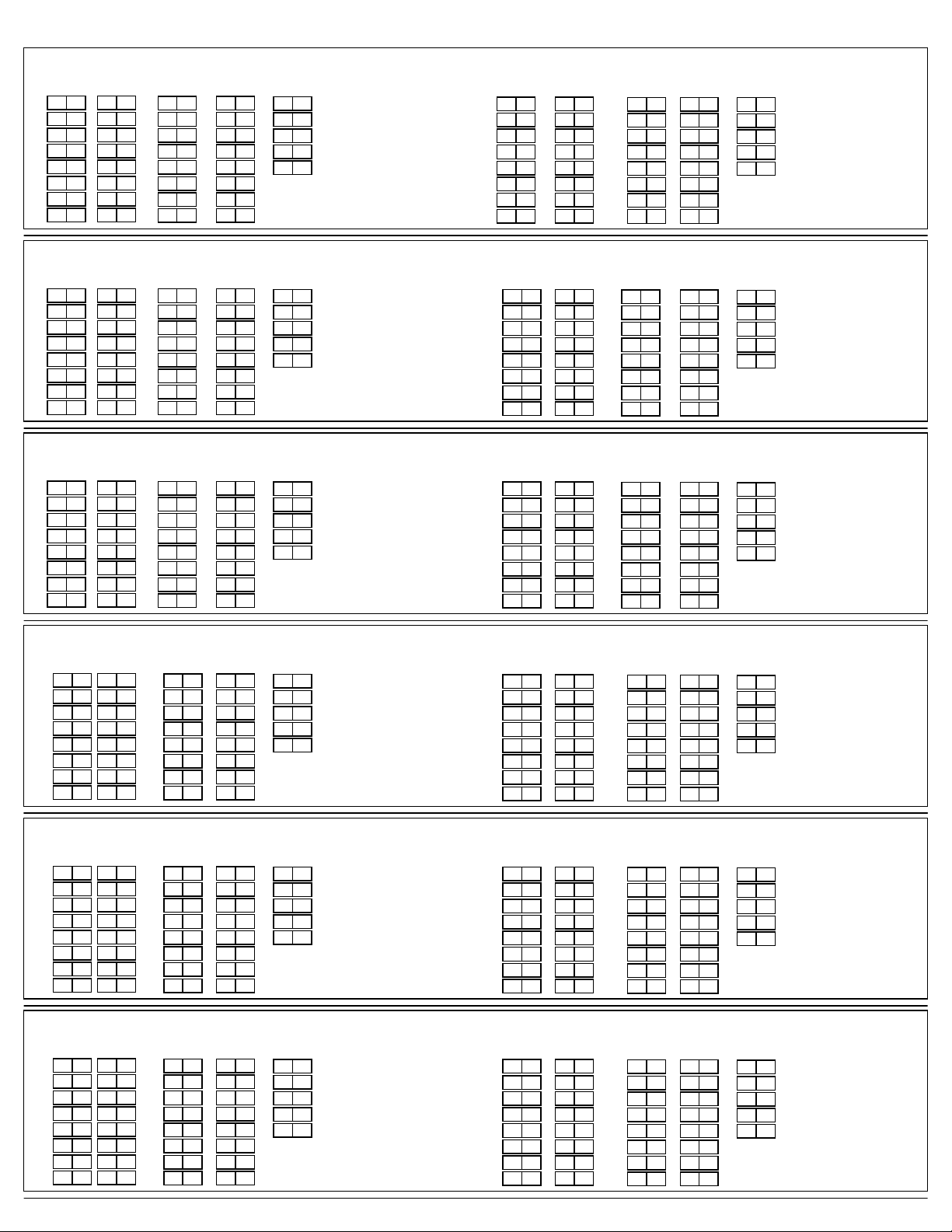
ALARM REPORT CODE & ID DIGITS FOR ZONES 97-128
[All codes default to 00]
Code
0 1 0 0
97
0 1 0 0
98
0 1 0 0
99
0 1 0 0
100
0 1 0 0
101
0 1 0 0
102
0 1 0 0
103
0 1 0 0
104
ALARM REPORT CODE & ID DIGITS FOR ZONES 129-160
[All codes default to 00]
Code
0 1 0 0
129
0 1 0 0
130
0 1 0 0
131
0 1 0 0
132
0 1 0 0
133
0 1 0 0
134
0 1 0 0
135
0 1 0 0
136
ALARM REPORT CODE & ID DIGITS FOR ZONES 161-192
[All codes default to 00]
Code
0 1 0 0
161
0 1 0 0
162
0 1 0 0
163
0 1 0 0
164
0 1 0 0
165
0 1 0 0
166
0 1 0 0
167
0 1 0 0
168
ID
ID
ID
Code
0 1 0 0
105
0 1 0 0
106
0 1 0 0
107
0 1 0 0
108
0 1 0 0
109
0 1 0 0
110
0 1 0 0
111
0 1 0 0
112
Code
0 1 0 0
137
0 1 0 0
138
0 1 0 0
139
0 1 0 0
140
0 1 0 0
141
0 1 0 0
142
0 1 0 0
143
0 1 0 0
144
Code
0 1 0 0
169
0 1 0 0
170
0 1 0 0
171
0 1 0 0
172
0 1 0 0
173
0 1 0 0
174
0 1 0 0
175
0 1 0 0
176
ID
ID
ID
0 0
0 0
0 0
0 0
0 0
0 0
0 0
0 0
0 0
0 0
0 0
0 0
0 0
0 0
0 0
Alarm Rst.
Trouble
Trouble Rst.
Bypass
Bypass Rst.
Alarm Rst.
Trouble
Trouble Rst.
Bypass
Bypass Rst.
Alarm Rst.
Trouble
Trouble Rst.
Bypass
Bypass Rst.
113
114
115
116
117
118
119
120
145
146
147
148
149
150
151
152
177
178
179
180
181
182
183
184
Code
Code
Code
0 1 0 0
0 1 0 0
0 1 0 0
0 1 0 0
0 1 0 0
0 1 0 0
0 1 0 0
0 1 0 0
0 1 0 0
0 1 0 0
0 1 0 0
0 1 0 0
0 1 0 0
0 1 0 0
0 1 0 0
0 1 0 0
0 1 0 0
0 1 0 0
0 1 0 0
0 1 0 0
0 1 0 0
0 1 0 0
0 1 0 0
0 1 0 0
ID
ID
ID
Code
0 1 0 0
121
0 1 0 0
122
0 1 0 0
123
0 1 0 0
124
0 1 0 0
125
0 1 0 0
126
0 1 0 0
127
0 1 0 0
128
Code
0 1 0 0
153
0 1 0 0
154
0 1 0 0
155
0 1 0 0
156
0 1 0 0
157
0 1 0 0
158
0 1 0 0
159
0 1 0 0
160
Code
0 1 0 0
185
0 1 0 0
186
0 1 0 0
187
0 1 0 0
188
0 1 0 0
189
0 1 0 0
190
0 1 0 0
191
0 1 0 0
192
ID
ID
ID
0 0
0 0
0 0
0 0
0 0
0 0
0 0
0 0
0 0
0 0
0 0
0 0
0 0
0 0
0 0
Alarm Rst.
Trouble
Trouble Rst.
Bypass
Bypass Rst.
Alarm Rst.
Trouble
Trouble Rst.
Bypass
Bypass Rst.
Alarm Rst.
Trouble
Trouble Rst.
Bypass
Bypass Rst.
-5a-
Vista250FBP-1
Rcvr-Acct#:
PRU - 7777
Date:
June 25, 2007 09:53 AM
Name:
ALARM REPORT CODE & ID DIGITS FOR ZONES 193-224
[All codes default to 00]
Code
0 1 0 0
193
0 1 0 0
194
0 1 0 0
195
0 1 0 0
196
0 1 0 0
197
0 1 0 0
198
0 1 0 0
199
0 1 0 0
200
ALARM REPORT CODE & ID DIGITS FOR ZONES 225-250
[All codes default to 00]
Code
0 1 0 0
225
0 1 0 0
226
0 1 0 0
227
0 1 0 0
228
0 1 0 0
229
0 1 0 0
230
0 1 0 0
231
0 1 0 0
232
NON-ALARM REPORT CODES 1ST & 2ND DIGITS
[All codes default to 00]
Closing
Opening
Low Battery
Low Battery Restore
AC Loss
ID
ID
LEONEL PRUEBAS
Code
0 1 0 0
201
0 1 0 0
202
0 1 0 0
203
0 1 0 0
204
0 1 0 0
205
0 1 0 0
206
0 1 0 0
207
0 1 0 0
208
Code
0 1 0 0
233
0 1 0 0
234
0 1 0 0
235
0 1 0 0
236
0 1 0 0
237
0 1 0 0
238
0 1 0 0
239
0 1 0 0
240
0 0
0 0
0 0
0 0
0 0
ID
ID
AC Restore
Test
Power-up
Cancel
Program Tamper
0 0
0 0
0 0
0 0
0 0
0 0
0 0
0 0
0 0
0 0
Alarm Rst.
Trouble
Trouble Rst.
Bypass
Bypass Rst.
Alarm Rst.
Trouble
Trouble Rst.
Bypass
Bypass Rst.
0 0
0 0
0 0
0 0
0 0
Business:
Code
0 1 0 0
209
0 1 0 0
210
0 1 0 0
211
0 1 0 0
212
0 1 0 0
213
0 1 0 0
214
0 1 0 0
215
0 1 0 0
216
Code
0 1 0 0
241
0 1 0 0
242
0 1 0 0
243
0 1 0 0
244
0 1 0 0
245
0 1 0 0
246
0 1 0 0
247
0 1 0 0
248
Armed Stay
Time/Date Set & Event Log Reset
Event Log 50% & 90% Full
Event Log Overflow
ID
ID
217
218
219
220
221
222
223
224
249
250
Code
Code
0 1 0 0
0 1 0 0
0 1 0 0
0 1 0 0
0 1 0 0
0 1 0 0
0 1 0 0
0 1 0 0
0 1 0 0
0 1 0 0
0 0
0 0
0 0
0 0
ID
0 0
0 0
0 0
0 0
0 0
ID
0 0
0 0
0 0
0 0
0 0
Exit Error-User Report
Recent Close
Walk Test Start
Walk Test Stop
Off-normal
Alarm Rst.
Trouble
Trouble Rst.
Bypass
Bypass Rst.
Alarm Rst.
Trouble
Trouble Rst.
Bypass
Bypass Rst.
0 0
0 0
0 0
0 0
0 0
ALARM REPORT CODE & ID DIGITS FOR RELAYS 1-16
[All codes default to 00]
601
602
603
604
605
606
607
608
Code
0 1 0 0
0 1 0 0
0 1 0 0
0 1 0 0
0 1 0 0
0 1 0 0
0 1 0 0
0 1 0 0
ID
609
610
611
612
613
614
615
616
Code
0 1 0 0
0 1 0 0
0 1 0 0
0 1 0 0
0 1 0 0
0 1 0 0
0 1 0 0
0 1 0 0
ID
0 0
0 0
0 0
0 0
0 0
Alarm Rst.
Trouble
Trouble Rst.
Bypass
Bypass Rst.
REPORT CODE & ID DIGITS FOR ECP ADDRESSES 0-16
800
801
802
803
804
805
806
807
Code
0 1 0 0
0 1 0 0
0 1 0 0
0 1 0 0
0 1 0 0
0 1 0 0
0 1 0 0
0 1 0 0
ID
808
809
810
811
812
813
814
815
Code
0 1 0 0
0 1 0 0
0 1 0 0
0 1 0 0
0 1 0 0
0 1 0 0
0 1 0 0
0 1 0 0
ID
0 0
0 0
0 0
0 0
0 0
Alarm Rst.
Trouble
Trouble Rst.
Bypass
Bypass Rst.
REPORT CODE & ID DIGITS FOR SYSTEM ZONES
970
971
972
973
974
975
976
977
Code
0 1 0 0
0 1 0 0
0 1 0 0
0 1 0 0
0 1 0 0
0 1 0 0
0 1 0 0
0 1 0 0
ID
0 0
0 0
0 0
0 0
0 0
Alarm Rst.
Trouble
Trouble Rst.
Bypass
Bypass Rst.
ALARM REPORT CODE & ID DIGITS FOR RELAYS 17-32
Code
0 1 0 0
617
0 1 0 0
618
0 1 0 0
619
0 1 0 0
620
0 1 0 0
621
0 1 0 0
622
0 1 0 0
623
0 1 0 0
624
REPORT CODE & ID DIGITS ECP ADDRESSES 17-30
Code
0 1 0 0
816
0 1 0 0
817
0 1 0 0
818
0 1 0 0
819
0 1 0 0
820
0 1 0 0
821
0 1 0 0
822
0 1 0 0
823
ID
ID
625
626
627
628
629
630
631
632
824
825
826
827
828
829
830
Code
0 1 0 0
0 1 0 0
0 1 0 0
0 1 0 0
0 1 0 0
0 1 0 0
0 1 0 0
0 1 0 0
Code
0 1 0 0
0 1 0 0
0 1 0 0
0 1 0 0
0 1 0 0
0 1 0 0
0 1 0 0
ID
ID
0 0
0 0
0 0
0 0
0 0
0 0
0 0
0 0
0 0
0 0
Alarm Rst.
Trouble
Trouble Rst.
Bypass
Bypass Rst.
Alarm Rst.
Trouble
Trouble Rst.
Bypass
Bypass Rst.
ALARM REPORT CODE & ID DIGITS FOR FIRE+PANIC ZONES
988
990
992
995
996
997
999
Code
0 1 0 0
0 1 0 0
0 1 0 0
0 1 0 0
0 1 0 0
0 1 0 0
0 1 0 0
ID
0 0
0 0
0 0
0 0
0 0
Alarm Rst.
Trouble
Trouble Rst.
Bypass
Bypass Rst.
-5b-
Vista250FBP-1

Rcvr-Acct#:
PRU - 7777
Date:
June 25, 2007 09:53 AM
Name:
LEONEL PRUEBAS
Business:
*93 OUTPUT RELAYS WORKSHEET
S T A R T S T O P ECP PARAMETERS
OUTPUT
RELAY # BELL (A) (EV) (ZL) (ZT) (ZL) (ZT) # SELECT
GROUP FIRE RSTRC ACTION
01
ADTNL RELAY START ZONE ZONE
ZONE #
0 0 0 1 1 5
EVENT
LIST TYPE
02 0 0 0 0 0 0
03 0 0 0 0 0 0
04 0 0 0 0 0 0
05 0 0 0 0 0 0
06 0 0 0 0 0 0
07 0 0 0 0 0 0
08 0 0 0 0 0 0
09 0 0 0 0 0 0
PART.
ACS ZONE ZONE PART. ACS RELAY ADDR RELAY/ RELAY/
POINT
6
1 00 1 2
0
0 00 0 0
0
0 00 0 0
0
0 00 0 0
0
0 00 0 0
0
0 00 0 0
0
0 00 0 0
0
0 00 0 0
0
0 00 0 0
LIST TYPE POINT TYPE TRIGGER TRIGGER
2
1 - 1 00 00 0
0
0 - 0 00 00 0
0
0 - 0 00 00 0
0
0 - 0 00 00 0
0
0 - 0 00 00 0
0
0 - 0 00 00 0
0
0 - 0 00 00 0
0
0 - 0 00 00 0
0
0 - 0 00 00 0
10 0 0 0 0 0 0
11 0 0 0 0 0 0
12 0 0 0 0 0 0
13 0 0 0 0 0 0
14 0 0 0 0 0 0
15 0 0 0 0 0 0
16 0 0 0 0 0 0
Where:
A = RELAY ACTION
EV = EVENT
ZL = ZONE LIST
ZT = ZONE TYPE/SYSTEM OPERATION
Choices for Zone Types are:
00 = Not Used 06 = 24 Hr Silent
01 = Entry/Exit 1
02 = Entry/Exit 2
03 = Perimeter
04 = Interior Follower
05 = Trouble Day/Alarm Night
27 = Access Point 30 = On 2nd Off
28 = MLB Supervision
29 = Momentary Exit
Choices for System Operation are:
14 = PLM Supervision
16 = Fire With Verification
17 = Fire Waterflow
18 = Fire Supervisory
19 = 24 Hour Trouble
20 = Arming-Stay
21 = Arming-Away
22 = Disarming (Code + OFF)
30 = On 2nd Off
31 = End of Exit Time
32 = Start of Entry Time
33 = Any Burglary Alarm
34 = Code + # + 71 Key Entry
35 = Code + # + 72 Key Entry
0 = No Response; 1 = Close for 2 sec; 2 = Close and stay closed; 3 = Pulse on and off; 4 = Toggle (Alternate ON/OFF)
0 = Not used; 1 = Alarm; 2 = Fault; 3 = Trouble; 4 = Restore
1,2,3,4,5,6,7 or 8. 0 = Not Used.
START ZONE LIST: Upon alarm, fault, or trouble of ANY zone on this list, relay action will START.
STOP ZONE LIST: Upon restore of ALL zones on this list, relay action will STOP.
It need not be same list as used for START.
07 = 24 Hr Audible
08 = 24 Hr Aux
09 = Fire Alarm or Trouble
10 = Interior w/Delay
23 = No Alarm Response
36 = At Bell Timeout or disarm,
37 = 2 X Bell Timeout or disarm,
38 = Chime
39 = Any Fire Alarm
40 = Bypassing
41 = AC Power Fail
42 = System Battery Low
43 = Communication Failure
44 = RF Low Battery
45 = Polling Loop Failure
47 = Console Failure
0
0 00 0 0
0
0 00 0 0
0
0 00 0 0
0
0 00 0 0
0
0 00 0 0
0
0 00 0 0
0
0 00 0 0
whichever 1st
whichever 1st
0
0 - 0 00 00 0
0
0 - 0 00 00 0
0
0 - 0 00 00 0
0
0 - 0 00 00 0
0
0 - 0 00 00 0
0
0 - 0 00 00 0
0
0 - 0 00 00 0
Any zone in "ZT" going into alarm,
Note:
fault, or trouble will actuate relay.
Any zone of that type that restores
will stop relay action.
51 = RF Receiver Failure
52 = Kissoff
54 = Fire Zone Reset
55 = Disarm + 1 minute
56 = XX minutes (Enter XX in field
1*74; stop condition only
57 = YY seconds (Enter YY in field
1*75; stop condition only
58 = Duress
60 = Two Way Audio
61 = Code + # + 67 Key Entry
62 = Bell 2 Timeout
63 = Aux. Relay Timeout
-6a-
Vista250FBP-1

Rcvr-Acct#:
PRU - 7777
Date:
June 25, 2007 09:53 AM
Name:
LEONEL PRUEBAS
Business:
*93 OUTPUT RELAYS WORKSHEET
S T A R T S T O P ECP PARAMETERS
OUTPUT
RELAY # BELL (A) (EV) (ZL) (ZT) (ZL) (ZT) # SELECT
GROUP FIRE RSTRC ACTION
17
ADTNL RELAY START ZONE ZONE
ZONE #
0 0 0 0 0 0
EVENT
LIST TYPE
18 0 0 0 0 0 0
19 0 0 0 0 0 0
20 0 0 0 0 0 0
21 0 0 0 0 0 0
22 0 0 0 0 0 0
23 0 0 0 0 0 0
24 0 0 0 0 0 0
25 0 0 0 0 0 0
PART.
ACS ZONE ZONE PART. ACS RELAY ADDR RELAY/ RELAY/
POINT
0
0 00 0 0
0
0 00 0 0
0
0 00 0 0
0
0 00 0 0
0
0 00 0 0
0
0 00 0 0
0
0 00 0 0
0
0 00 0 0
0
0 00 0 0
LIST TYPE POINT TYPE TRIGGER TRIGGER
0
0 - 0 00 00 0
0
0 - 0 00 00 0
0
0 - 0 00 00 0
0
0 - 0 00 00 0
0
0 - 0 00 00 0
0
0 - 0 00 00 0
0
0 - 0 00 00 0
0
0 - 0 00 00 0
0
0 - 0 00 00 0
26 0 0 0 0 0 0
27 0 0 0 0 0 0
28 0 0 0 0 0 0
29 0 0 0 0 0 0
30 0 0 0 0 0 0
31 0 0 0 0 0 0
32 0 0 0 0 0 0
Where:
A = RELAY ACTION
EV = EVENT
ZL = ZONE LIST
ZT = ZONE TYPE/SYSTEM OPERATION
Choices for Zone Types are:
00 = Not Used 06 = 24 Hr Silent
01 = Entry/Exit 1
02 = Entry/Exit 2
03 = Perimeter
04 = Interior Follower
05 = Trouble Day/Alarm Night
27 = Access Point 30 = On 2nd Off
28 = MLB Supervision
29 = Momentary Exit
Choices for System Operation are:
14 = PLM Supervision
16 = Fire With Verification
17 = Fire Waterflow
18 = Fire Supervisory
19 = 24 Hour Trouble
20 = Arming-Stay
21 = Arming-Away
22 = Disarming (Code + OFF)
30 = On 2nd Off
31 = End of Exit Time
32 = Start of Entry Time
33 = Any Burglary Alarm
34 = Code + # + 71 Key Entry
35 = Code + # + 72 Key Entry
0 = No Response; 1 = Close for 2 sec; 2 = Close and stay closed; 3 = Pulse on and off; 4 = Toggle (Alternate ON/OFF)
0 = Not used; 1 = Alarm; 2 = Fault; 3 = Trouble; 4 = Restore
1,2,3,4,5,6,7 or 8. 0 = Not Used.
START ZONE LIST: Upon alarm, fault, or trouble of ANY zone on this list, relay action will START.
STOP ZONE LIST: Upon restore of ALL zones on this list, relay action will STOP.
It need not be same list as used for START.
07 = 24 Hr Audible
08 = 24 Hr Aux
09 = Fire Alarm or Trouble
10 = Interior w/Delay
23 = No Alarm Response
36 = At Bell Timeout or disarm,
37 = 2 X Bell Timeout or disarm,
38 = Chime
39 = Any Fire Alarm
40 = Bypassing
41 = AC Power Fail
42 = System Battery Low
43 = Communication Failure
44 = RF Low Battery
45 = Polling Loop Failure
47 = Console Failure
0
0 00 0 0
0
0 00 0 0
0
0 00 0 0
0
0 00 0 0
0
0 00 0 0
0
0 00 0 0
0
0 00 0 0
whichever 1st
whichever 1st
0
0 - 0 00 00 0
0
0 - 0 00 00 0
0
0 - 0 00 00 0
0
0 - 0 00 00 0
0
0 - 0 00 00 0
0
0 - 0 00 00 0
0
0 - 0 00 00 0
Any zone in "ZT" going into alarm,
Note:
fault, or trouble will actuate relay.
Any zone of that type that restores
will stop relay action.
51 = RF Receiver Failure
52 = Kissoff
54 = Fire Zone Reset
55 = Disarm + 1 minute
56 = XX minutes (Enter XX in field
1*74; stop condition only
57 = YY seconds (Enter YY in field
1*75; stop condition only
58 = Duress
60 = Two Way Audio
61 = Code + # + 67 Key Entry
62 = Bell 2 Timeout
63 = Aux. Relay Timeout
-6b-
Vista250FBP-1

Rcvr-Acct#:
PRU - 7777
Date:
June 25, 2007 09:53 AM
Name:
LEONEL PRUEBAS
Business:
*93 OUTPUT RELAYS WORKSHEET
S T A R T S T O P ECP PARAMETERS
OUTPUT
RELAY # BELL (A) (EV) (ZL) (ZT) (ZL) (ZT) # SELECT
GROUP FIRE RSTRC ACTION
33
ADTNL RELAY START ZONE ZONE
ZONE #
0 0 0 0 0 0
EVENT
LIST TYPE
34 0 0 0 0 0 0
35 0 0 0 0 0 0
36 0 0 0 0 0 0
37 0 0 0 0 0 0
38 0 0 0 0 0 0
39 0 0 0 0 0 0
40 0 0 0 0 0 0
41 0 0 0 0 0 0
PART.
ACS ZONE ZONE PART. ACS RELAY ADDR RELAY/ RELAY/
POINT
0
0 00 0 0
0
0 00 0 0
0
0 00 0 0
0
0 00 0 0
0
0 00 0 0
0
0 00 0 0
0
0 00 0 0
0
0 00 0 0
0
0 00 0 0
LIST TYPE POINT TYPE TRIGGER TRIGGER
0
0 - 0 00 00 0
0
0 - 0 00 00 0
0
0 - 0 00 00 0
0
0 - 0 00 00 0
0
0 - 0 00 00 0
0
0 - 0 00 00 0
0
0 - 0 00 00 0
0
0 - 0 00 00 0
0
0 - 0 00 00 0
42 0 0 0 0 0 0
43 0 0 0 0 0 0
44 0 0 0 0 0 0
45 0 0 0 0 0 0
46 0 0 0 0 0 0
47 0 0 0 0 0 0
48 0 0 0 0 0 0
Where:
A = RELAY ACTION
EV = EVENT
ZL = ZONE LIST
ZT = ZONE TYPE/SYSTEM OPERATION
Choices for Zone Types are:
00 = Not Used 06 = 24 Hr Silent
01 = Entry/Exit 1
02 = Entry/Exit 2
03 = Perimeter
04 = Interior Follower
05 = Trouble Day/Alarm Night
27 = Access Point 30 = On 2nd Off
28 = MLB Supervision
29 = Momentary Exit
Choices for System Operation are:
14 = PLM Supervision
16 = Fire With Verification
17 = Fire Waterflow
18 = Fire Supervisory
19 = 24 Hour Trouble
20 = Arming-Stay
21 = Arming-Away
22 = Disarming (Code + OFF)
30 = On 2nd Off
31 = End of Exit Time
32 = Start of Entry Time
33 = Any Burglary Alarm
34 = Code + # + 71 Key Entry
35 = Code + # + 72 Key Entry
0 = No Response; 1 = Close for 2 sec; 2 = Close and stay closed; 3 = Pulse on and off; 4 = Toggle (Alternate ON/OFF)
0 = Not used; 1 = Alarm; 2 = Fault; 3 = Trouble; 4 = Restore
1,2,3,4,5,6,7 or 8. 0 = Not Used.
START ZONE LIST: Upon alarm, fault, or trouble of ANY zone on this list, relay action will START.
STOP ZONE LIST: Upon restore of ALL zones on this list, relay action will STOP.
It need not be same list as used for START.
07 = 24 Hr Audible
08 = 24 Hr Aux
09 = Fire Alarm or Trouble
10 = Interior w/Delay
23 = No Alarm Response
36 = At Bell Timeout or disarm,
37 = 2 X Bell Timeout or disarm,
38 = Chime
39 = Any Fire Alarm
40 = Bypassing
41 = AC Power Fail
42 = System Battery Low
43 = Communication Failure
44 = RF Low Battery
45 = Polling Loop Failure
47 = Console Failure
0
0 00 0 0
0
0 00 0 0
0
0 00 0 0
0
0 00 0 0
0
0 00 0 0
0
0 00 0 0
0
0 00 0 0
whichever 1st
whichever 1st
0
0 - 0 00 00 0
0
0 - 0 00 00 0
0
0 - 0 00 00 0
0
0 - 0 00 00 0
0
0 - 0 00 00 0
0
0 - 0 00 00 0
0
0 - 0 00 00 0
Any zone in "ZT" going into alarm,
Note:
fault, or trouble will actuate relay.
Any zone of that type that restores
will stop relay action.
51 = RF Receiver Failure
52 = Kissoff
54 = Fire Zone Reset
55 = Disarm + 1 minute
56 = XX minutes (Enter XX in field
1*74; stop condition only
57 = YY seconds (Enter YY in field
1*75; stop condition only
58 = Duress
60 = Two Way Audio
61 = Code + # + 67 Key Entry
62 = Bell 2 Timeout
63 = Aux. Relay Timeout
-6c-
Vista250FBP-1

Rcvr-Acct#:
PRU - 7777
Date:
June 25, 2007 09:53 AM
Name:
LEONEL PRUEBAS
Business:
*93 OUTPUT RELAYS WORKSHEET
S T A R T S T O P ECP PARAMETERS
OUTPUT
RELAY # BELL (A) (EV) (ZL) (ZT) (ZL) (ZT) # SELECT
GROUP FIRE RSTRC ACTION
49
ADTNL RELAY START ZONE ZONE
ZONE #
0 0 0 0 0 0
EVENT
LIST TYPE
50 0 0 0 0 0 0
51 0 0 0 0 0 0
52 0 0 0 0 0 0
53 0 0 0 0 0 0
54 0 0 0 0 0 0
55 0 0 0 0 0 0
56 0 0 0 0 0 0
57 0 0 0 0 0 0
PART.
ACS ZONE ZONE PART. ACS RELAY ADDR RELAY/ RELAY/
POINT
0
0 00 0 0
0
0 00 0 0
0
0 00 0 0
0
0 00 0 0
0
0 00 0 0
0
0 00 0 0
0
0 00 0 0
0
0 00 0 0
0
0 00 0 0
LIST TYPE POINT TYPE TRIGGER TRIGGER
0
0 - 0 00 00 0
0
0 - 0 00 00 0
0
0 - 0 00 00 0
0
0 - 0 00 00 0
0
0 - 0 00 00 0
0
0 - 0 00 00 0
0
0 - 0 00 00 0
0
0 - 0 00 00 0
0
0 - 0 00 00 0
58 0 0 0 0 0 0
59 0 0 0 0 0 0
60 0 0 0 0 0 0
61 0 0 0 0 0 0
62 0 0 0 0 0 0
63 0 0 0 0 0 0
64 0 0 0 0 0 0
Where:
A = RELAY ACTION
EV = EVENT
ZL = ZONE LIST
ZT = ZONE TYPE/SYSTEM OPERATION
Choices for Zone Types are:
00 = Not Used 06 = 24 Hr Silent
01 = Entry/Exit 1
02 = Entry/Exit 2
03 = Perimeter
04 = Interior Follower
05 = Trouble Day/Alarm Night
27 = Access Point 30 = On 2nd Off
28 = MLB Supervision
29 = Momentary Exit
Choices for System Operation are:
14 = PLM Supervision
16 = Fire With Verification
17 = Fire Waterflow
18 = Fire Supervisory
19 = 24 Hour Trouble
20 = Arming-Stay
21 = Arming-Away
22 = Disarming (Code + OFF)
30 = On 2nd Off
31 = End of Exit Time
32 = Start of Entry Time
33 = Any Burglary Alarm
34 = Code + # + 71 Key Entry
35 = Code + # + 72 Key Entry
0 = No Response; 1 = Close for 2 sec; 2 = Close and stay closed; 3 = Pulse on and off; 4 = Toggle (Alternate ON/OFF)
0 = Not used; 1 = Alarm; 2 = Fault; 3 = Trouble; 4 = Restore
1,2,3,4,5,6,7 or 8. 0 = Not Used.
START ZONE LIST: Upon alarm, fault, or trouble of ANY zone on this list, relay action will START.
STOP ZONE LIST: Upon restore of ALL zones on this list, relay action will STOP.
It need not be same list as used for START.
07 = 24 Hr Audible
08 = 24 Hr Aux
09 = Fire Alarm or Trouble
10 = Interior w/Delay
23 = No Alarm Response
36 = At Bell Timeout or disarm,
37 = 2 X Bell Timeout or disarm,
38 = Chime
39 = Any Fire Alarm
40 = Bypassing
41 = AC Power Fail
42 = System Battery Low
43 = Communication Failure
44 = RF Low Battery
45 = Polling Loop Failure
47 = Console Failure
0
0 00 0 0
0
0 00 0 0
0
0 00 0 0
0
0 00 0 0
0
0 00 0 0
0
0 00 0 0
0
0 00 0 0
whichever 1st
whichever 1st
0
0 - 0 00 00 0
0
0 - 0 00 00 0
0
0 - 0 00 00 0
0
0 - 0 00 00 0
0
0 - 0 00 00 0
0
0 - 0 00 00 0
0
0 - 0 00 00 0
Any zone in "ZT" going into alarm,
Note:
fault, or trouble will actuate relay.
Any zone of that type that restores
will stop relay action.
51 = RF Receiver Failure
52 = Kissoff
54 = Fire Zone Reset
55 = Disarm + 1 minute
56 = XX minutes (Enter XX in field
1*74; stop condition only
57 = YY seconds (Enter YY in field
1*75; stop condition only
58 = Duress
60 = Two Way Audio
61 = Code + # + 67 Key Entry
62 = Bell 2 Timeout
63 = Aux. Relay Timeout
-6d-
Vista250FBP-1

Rcvr-Acct#:
PRU - 7777
Date:
June 25, 2007 09:53 AM
Name:
LEONEL PRUEBAS
Business:
*93 OUTPUT RELAYS WORKSHEET
S T A R T S T O P ECP PARAMETERS
OUTPUT
RELAY # BELL (A) (EV) (ZL) (ZT) (ZL) (ZT) # SELECT
GROUP FIRE RSTRC ACTION
65
ADTNL RELAY START ZONE ZONE
ZONE #
0 0 0 0 0 0
EVENT
LIST TYPE
66 0 0 0 0 0 0
67 0 0 0 0 0 0
68 0 0 0 0 0 0
69 0 0 0 0 0 0
70 0 0 0 0 0 0
71 0 0 0 0 0 0
72 0 0 0 0 0 0
73 0 0 0 0 0 0
PART.
ACS ZONE ZONE PART. ACS RELAY ADDR RELAY/ RELAY/
POINT
0
0 00 0 0
0
0 00 0 0
0
0 00 0 0
0
0 00 0 0
0
0 00 0 0
0
0 00 0 0
0
0 00 0 0
0
0 00 0 0
0
0 00 0 0
LIST TYPE POINT TYPE TRIGGER TRIGGER
0
0 - 0 00 00 0
0
0 - 0 00 00 0
0
0 - 0 00 00 0
0
0 - 0 00 00 0
0
0 - 0 00 00 0
0
0 - 0 00 00 0
0
0 - 0 00 00 0
0
0 - 0 00 00 0
0
0 - 0 00 00 0
74 0 0 0 0 0 0
75 0 0 0 0 0 0
76 0 0 0 0 0 0
77 0 0 0 0 0 0
78 0 0 0 0 0 0
79 0 0 0 0 0 0
80 0 0 0 0 0 0
Where:
A = RELAY ACTION
EV = EVENT
ZL = ZONE LIST
ZT = ZONE TYPE/SYSTEM OPERATION
Choices for Zone Types are:
00 = Not Used 06 = 24 Hr Silent
01 = Entry/Exit 1
02 = Entry/Exit 2
03 = Perimeter
04 = Interior Follower
05 = Trouble Day/Alarm Night
27 = Access Point 30 = On 2nd Off
28 = MLB Supervision
29 = Momentary Exit
Choices for System Operation are:
14 = PLM Supervision
16 = Fire With Verification
17 = Fire Waterflow
18 = Fire Supervisory
19 = 24 Hour Trouble
20 = Arming-Stay
21 = Arming-Away
22 = Disarming (Code + OFF)
30 = On 2nd Off
31 = End of Exit Time
32 = Start of Entry Time
33 = Any Burglary Alarm
34 = Code + # + 71 Key Entry
35 = Code + # + 72 Key Entry
0 = No Response; 1 = Close for 2 sec; 2 = Close and stay closed; 3 = Pulse on and off; 4 = Toggle (Alternate ON/OFF)
0 = Not used; 1 = Alarm; 2 = Fault; 3 = Trouble; 4 = Restore
1,2,3,4,5,6,7 or 8. 0 = Not Used.
START ZONE LIST: Upon alarm, fault, or trouble of ANY zone on this list, relay action will START.
STOP ZONE LIST: Upon restore of ALL zones on this list, relay action will STOP.
It need not be same list as used for START.
07 = 24 Hr Audible
08 = 24 Hr Aux
09 = Fire Alarm or Trouble
10 = Interior w/Delay
23 = No Alarm Response
36 = At Bell Timeout or disarm,
37 = 2 X Bell Timeout or disarm,
38 = Chime
39 = Any Fire Alarm
40 = Bypassing
41 = AC Power Fail
42 = System Battery Low
43 = Communication Failure
44 = RF Low Battery
45 = Polling Loop Failure
47 = Console Failure
0
0 00 0 0
0
0 00 0 0
0
0 00 0 0
0
0 00 0 0
0
0 00 0 0
0
0 00 0 0
0
0 00 0 0
whichever 1st
whichever 1st
0
0 - 0 00 00 0
0
0 - 0 00 00 0
0
0 - 0 00 00 0
0
0 - 0 00 00 0
0
0 - 0 00 00 0
0
0 - 0 00 00 0
0
0 - 0 00 00 0
Any zone in "ZT" going into alarm,
Note:
fault, or trouble will actuate relay.
Any zone of that type that restores
will stop relay action.
51 = RF Receiver Failure
52 = Kissoff
54 = Fire Zone Reset
55 = Disarm + 1 minute
56 = XX minutes (Enter XX in field
1*74; stop condition only
57 = YY seconds (Enter YY in field
1*75; stop condition only
58 = Duress
60 = Two Way Audio
61 = Code + # + 67 Key Entry
62 = Bell 2 Timeout
63 = Aux. Relay Timeout
-6e-
Vista250FBP-1

Rcvr-Acct#:
PRU - 7777
Date:
June 25, 2007 09:53 AM
Name:
LEONEL PRUEBAS
Business:
*93 OUTPUT RELAYS WORKSHEET
S T A R T S T O P ECP PARAMETERS
OUTPUT
RELAY # BELL (A) (EV) (ZL) (ZT) (ZL) (ZT) # SELECT
GROUP FIRE RSTRC ACTION
81
ADTNL RELAY START ZONE ZONE
ZONE #
0 0 0 0 0 0
EVENT
LIST TYPE
82 0 0 0 0 0 0
83 0 0 0 0 0 0
84 0 0 0 0 0 0
85 0 0 0 0 0 0
86 0 0 0 0 0 0
87 0 0 0 0 0 0
88 0 0 0 0 0 0
89 0 0 0 0 0 0
PART.
ACS ZONE ZONE PART. ACS RELAY ADDR RELAY/ RELAY/
POINT
0
0 00 0 0
0
0 00 0 0
0
0 00 0 0
0
0 00 0 0
0
0 00 0 0
0
0 00 0 0
0
0 00 0 0
0
0 00 0 0
0
0 00 0 0
LIST TYPE POINT TYPE TRIGGER TRIGGER
0
0 - 0 00 00 0
0
0 - 0 00 00 0
0
0 - 0 00 00 0
0
0 - 0 00 00 0
0
0 - 0 00 00 0
0
0 - 0 00 00 0
0
0 - 0 00 00 0
0
0 - 0 00 00 0
0
0 - 0 00 00 0
90 0 0 0 0 0 0
91 0 0 0 0 0 0
92 0 0 0 0 0 0
93 0 0 0 0 0 0
94 0 0 0 0 0 0
95 0 0 0 0 0 0
96 0 0 0 0 0 0
Where:
A = RELAY ACTION
EV = EVENT
ZL = ZONE LIST
ZT = ZONE TYPE/SYSTEM OPERATION
Choices for Zone Types are:
00 = Not Used 06 = 24 Hr Silent
01 = Entry/Exit 1
02 = Entry/Exit 2
03 = Perimeter
04 = Interior Follower
05 = Trouble Day/Alarm Night
27 = Access Point 30 = On 2nd Off
28 = MLB Supervision
29 = Momentary Exit
Choices for System Operation are:
14 = PLM Supervision
16 = Fire With Verification
17 = Fire Waterflow
18 = Fire Supervisory
19 = 24 Hour Trouble
20 = Arming-Stay
21 = Arming-Away
22 = Disarming (Code + OFF)
30 = On 2nd Off
31 = End of Exit Time
32 = Start of Entry Time
33 = Any Burglary Alarm
34 = Code + # + 71 Key Entry
35 = Code + # + 72 Key Entry
0 = No Response; 1 = Close for 2 sec; 2 = Close and stay closed; 3 = Pulse on and off; 4 = Toggle (Alternate ON/OFF)
0 = Not used; 1 = Alarm; 2 = Fault; 3 = Trouble; 4 = Restore
1,2,3,4,5,6,7 or 8. 0 = Not Used.
START ZONE LIST: Upon alarm, fault, or trouble of ANY zone on this list, relay action will START.
STOP ZONE LIST: Upon restore of ALL zones on this list, relay action will STOP.
It need not be same list as used for START.
07 = 24 Hr Audible
08 = 24 Hr Aux
09 = Fire Alarm or Trouble
10 = Interior w/Delay
23 = No Alarm Response
36 = At Bell Timeout or disarm,
37 = 2 X Bell Timeout or disarm,
38 = Chime
39 = Any Fire Alarm
40 = Bypassing
41 = AC Power Fail
42 = System Battery Low
43 = Communication Failure
44 = RF Low Battery
45 = Polling Loop Failure
47 = Console Failure
0
0 00 0 0
0
0 00 0 0
0
0 00 0 0
0
0 00 0 0
0
0 00 0 0
0
0 00 0 0
0
0 00 0 0
whichever 1st
whichever 1st
0
0 - 0 00 00 0
0
0 - 0 00 00 0
0
0 - 0 00 00 0
0
0 - 0 00 00 0
0
0 - 0 00 00 0
0
0 - 0 00 00 0
0
0 - 0 00 00 0
Any zone in "ZT" going into alarm,
Note:
fault, or trouble will actuate relay.
Any zone of that type that restores
will stop relay action.
51 = RF Receiver Failure
52 = Kissoff
54 = Fire Zone Reset
55 = Disarm + 1 minute
56 = XX minutes (Enter XX in field
1*74; stop condition only
57 = YY seconds (Enter YY in field
1*75; stop condition only
58 = Duress
60 = Two Way Audio
61 = Code + # + 67 Key Entry
62 = Bell 2 Timeout
63 = Aux. Relay Timeout
-6f-
Vista250FBP-1

Rcvr-Acct#:
PRU - 7777
Date:
June 25, 2007 09:53 AM
Name:
LEONEL PRUEBAS
*93 RELAY VOICE DESCRIPTORS
OUTPUT
RELAY DESCRIPTOR 1 DESCRIPTOR 2 DESCRIPTOR 3
1 ALARM ALARM ALARM
2 ALARM ALARM ALARM
3 ALARM ALARM ALARM
4 ALARM ALARM ALARM
5 ALARM ALARM ALARM
6 ALARM ALARM ALARM
7 ALARM ALARM ALARM
8 ALARM ALARM ALARM
9 ALARM ALARM ALARM
10 ALARM ALARM ALARM
11 ALARM ALARM ALARM
12 ALARM ALARM ALARM
13 ALARM ALARM ALARM
14 ALARM ALARM ALARM
15 ALARM ALARM ALARM
16 ALARM ALARM ALARM
*93 ZONE LISTS FOR OUTPUT RELAYS
VOICE VOICE VOICE
Zone List 1
0 0 1,0 0 3,0 0 6
Zone List 2
Zone List 3
Zone List 4
Zone List 5
Zone List 6
Zone List 7
Zone List 8
: Started or stopped by zone numbers (enter 00 to end entries).
,
: Started or stopped by zone numbers (enter 00 to end entries).
,
: Started or stopped by zone numbers (enter 00 to end entries).
,
: Started or stopped by zone numbers (enter 00 to end entries).
,
: Started or stopped by zone numbers (enter 00 to end entries).
,
: Started or stopped by zone numbers (enter 00 to end entries).
,
: Started or stopped by zone numbers (enter 00 to end entries).
,
: Started or stopped by zone numbers (enter 00 to end entries).
,
,
,
,
,
,
,
,
,
,
,
,
,
,
,
Record desired zone numbers. More or fewer boxes than shown may be
needed, since any list may include any or all of system's zone numbers.
,
,
,
,
,
,
,
Business:
OUTPUT
RELAY DESCRIPTOR 1 DESCRIPTOR 2 DESCRIPTOR 3
17 ALARM ALARM ALARM
18 ALARM ALARM ALARM
19 ALARM ALARM ALARM
20 ALARM ALARM ALARM
21 ALARM ALARM ALARM
22 ALARM ALARM ALARM
23 ALARM ALARM ALARM
24 ALARM ALARM ALARM
25 ALARM ALARM ALARM
26 ALARM ALARM ALARM
27 ALARM ALARM ALARM
28 ALARM ALARM ALARM
29 ALARM ALARM ALARM
30 ALARM ALARM ALARM
31 ALARM ALARM ALARM
32 ALARM ALARM ALARM
,
,
,
,
,
,
,
VOICE VOICE VOICE
,
,
,
,
,
,
,
,
,
,
,
,
,
,
,
,
,
,
,
,
,
...etc.
...etc.
...etc.
...etc.
...etc.
...etc.
...etc.

Zone List 9
Zone List 10
Zone List 11
Zone List 12
Zone List 13
Zone List 14
Zone List 15
: Started or stopped by zone numbers (enter 00 to end entries).
,
: Started or stopped by zone numbers (enter 00 to end entries).
,
: Started or stopped by zone numbers (enter 00 to end entries).
,
: Started or stopped by zone numbers (enter 00 to end entries).
,
: Started or stopped by zone numbers (enter 00 to end entries).
,
: Started or stopped by zone numbers (enter 00 to end entries).
,
: Started or stopped by zone numbers (enter 00 to end entries).
,
,
,
,
,
,
,
,
,
,
,
,
,
,
,
,
,
,
,
,
,
,
,
,
,
,
,
,
,
,
,
,
,
,
,
,
,
,
,
,
,
,
,
,
,
,
,
,
,
,
...etc.
...etc.
...etc.
...etc.
...etc.
...etc.
...etc.
-7-
Vista250FBP-1

Rcvr-Acct#:
Name:
Card Enrollment Card Card Exec Trace Vista Access Group Use Expiration
# # Name Actv Prvlg User # 1 2 3 4 5 6 7 8 Month Day Count
1 000000000000 X 0 -- -- --
2 000000000000 X 0 -- -- -3 000000000000 X 0 -- -- -4 000000000000 X 0 -- -- -5 000000000000 X 0 -- -- -6 000000000000 X 0 -- -- -7 000000000000 X 0 -- -- -8 000000000000 X 0 -- -- --
9 000000000000 X 0 -- -- -10 000000000000 X 0 -- -- -11 000000000000 X 0 -- -- -12 000000000000 X 0 -- -- -13 000000000000 X 0 -- -- -14 000000000000 X 0 -- -- -15 000000000000 X 0 -- -- -16 000000000000 X 0 -- -- -17 000000000000 X 0 -- -- -18 000000000000 X 0 -- -- -19 000000000000 X 0 -- -- -20 000000000000 X 0 -- -- -21 000000000000 X 0 -- -- -22 000000000000 X 0 -- -- -23 000000000000 X 0 -- -- -24 000000000000 X 0 -- -- -25 000000000000 X 0 -- -- -26 000000000000 X 0 -- -- -27 000000000000 X 0 -- -- -28 000000000000 X 0 -- -- -29 000000000000 X 0 -- -- -30 000000000000 X 0 -- -- -31 000000000000 X 0 -- -- -32 000000000000 X 0 -- -- -33 000000000000 X 0 -- -- -34 000000000000 X 0 -- -- -35 000000000000 X 0 -- -- -36 000000000000 X 0 -- -- -37 000000000000 X 0 -- -- -38 000000000000 X 0 -- -- -39 000000000000 X 0 -- -- -40 000000000000 X 0 -- -- -41 000000000000 X 0 -- -- -42 000000000000 X 0 -- -- -43 000000000000 X 0 -- -- -44 000000000000 X 0 -- -- -45 000000000000 X 0 -- -- -46 000000000000 X 0 -- -- -47 000000000000 X 0 -- -- -48 000000000000 X 0 -- -- -49 000000000000 X 0 -- -- -50 000000000000 X 0 -- -- --
PRU - 7777
LEONEL PRUEBAS
Date:
Business:
June 25, 2007 09:53 AM
Card Action Action Invoke Event
# Desired Specifier Action Specifier
1 Not Used 0 0 never invoked Not Used
2 Not Used 0 0 never invoked Not Used
3 Not Used 0 0 never invoked Not Used
4 Not Used 0 0 never invoked Not Used
5 Not Used 0 0 never invoked Not Used
6 Not Used 0 0 never invoked Not Used
7 Not Used 0 0 never invoked Not Used
8 Not Used 0 0 never invoked Not Used
9 Not Used 0 0 never invoked Not Used
10 Not Used 0 0 never invoked Not Used
11 Not Used 0 0 never invoked Not Used
12 Not Used 0 0 never invoked Not Used
13 Not Used 0 0 never invoked Not Used
14 Not Used 0 0 never invoked Not Used
15 Not Used 0 0 never invoked Not Used
16 Not Used 0 0 never invoked Not Used
17 Not Used 0 0 never invoked Not Used
18 Not Used 0 0 never invoked Not Used
19 Not Used 0 0 never invoked Not Used
20 Not Used 0 0 never invoked Not Used
21 Not Used 0 0 never invoked Not Used
22 Not Used 0 0 never invoked Not Used
23 Not Used 0 0 never invoked Not Used
24 Not Used 0 0 never invoked Not Used
25 Not Used 0 0 never invoked Not Used
26 Not Used 0 0 never invoked Not Used
27 Not Used 0 0 never invoked Not Used
28 Not Used 0 0 never invoked Not Used
29 Not Used 0 0 never invoked Not Used
30 Not Used 0 0 never invoked Not Used
31 Not Used 0 0 never invoked Not Used
32 Not Used 0 0 never invoked Not Used
33 Not Used 0 0 never invoked Not Used
34 Not Used 0 0 never invoked Not Used
35 Not Used 0 0 never invoked Not Used
36 Not Used 0 0 never invoked Not Used
37 Not Used 0 0 never invoked Not Used
38 Not Used 0 0 never invoked Not Used
39 Not Used 0 0 never invoked Not Used
40 Not Used 0 0 never invoked Not Used
41 Not Used 0 0 never invoked Not Used
42 Not Used 0 0 never invoked Not Used
43 Not Used 0 0 never invoked Not Used
44 Not Used 0 0 never invoked Not Used
45 Not Used 0 0 never invoked Not Used
46 Not Used 0 0 never invoked Not Used
47 Not Used 0 0 never invoked Not Used
48 Not Used 0 0 never invoked Not Used
49 Not Used 0 0 never invoked Not Used
50 Not Used 0 0 never invoked Not Used
Data for Cards 1 to 50
Vista250FBP-1

Rcvr-Acct#:
Name:
Card Enrollment Card Card Exec Trace Vista Access Group Use Expiration
# # Name Actv Prvlg User # 1 2 3 4 5 6 7 8 Month Day Count
51 000000000000 X 0 -- -- --
52 000000000000 X 0 -- -- -53 000000000000 X 0 -- -- -54 000000000000 X 0 -- -- -55 000000000000 X 0 -- -- -56 000000000000 X 0 -- -- -57 000000000000 X 0 -- -- -58 000000000000 X 0 -- -- -59 000000000000 X 0 -- -- -60 000000000000 X 0 -- -- -61 000000000000 X 0 -- -- -62 000000000000 X 0 -- -- -63 000000000000 X 0 -- -- -64 000000000000 X 0 -- -- -65 000000000000 X 0 -- -- -66 000000000000 X 0 -- -- -67 000000000000 X 0 -- -- -68 000000000000 X 0 -- -- -69 000000000000 X 0 -- -- -70 000000000000 X 0 -- -- -71 000000000000 X 0 -- -- -72 000000000000 X 0 -- -- -73 000000000000 X 0 -- -- -74 000000000000 X 0 -- -- -75 000000000000 X 0 -- -- -76 000000000000 X 0 -- -- -77 000000000000 X 0 -- -- -78 000000000000 X 0 -- -- -79 000000000000 X 0 -- -- -80 000000000000 X 0 -- -- -81 000000000000 X 0 -- -- -82 000000000000 X 0 -- -- -83 000000000000 X 0 -- -- -84 000000000000 X 0 -- -- -85 000000000000 X 0 -- -- -86 000000000000 X 0 -- -- -87 000000000000 X 0 -- -- -88 000000000000 X 0 -- -- -89 000000000000 X 0 -- -- -90 000000000000 X 0 -- -- -91 000000000000 X 0 -- -- -92 000000000000 X 0 -- -- -93 000000000000 X 0 -- -- -94 000000000000 X 0 -- -- -95 000000000000 X 0 -- -- -96 000000000000 X 0 -- -- -97 000000000000 X 0 -- -- -98 000000000000 X 0 -- -- -99 000000000000 X 0 -- -- --
100 000000000000 X 0 -- -- --
PRU - 7777
LEONEL PRUEBAS
Date:
Business:
June 25, 2007 09:53 AM
Card Action Action Invoke Event
# Desired Specifier Action Specifier
51 Not Used 0 0 never invoked Not Used
52 Not Used 0 0 never invoked Not Used
53 Not Used 0 0 never invoked Not Used
54 Not Used 0 0 never invoked Not Used
55 Not Used 0 0 never invoked Not Used
56 Not Used 0 0 never invoked Not Used
57 Not Used 0 0 never invoked Not Used
58 Not Used 0 0 never invoked Not Used
59 Not Used 0 0 never invoked Not Used
60 Not Used 0 0 never invoked Not Used
61 Not Used 0 0 never invoked Not Used
62 Not Used 0 0 never invoked Not Used
63 Not Used 0 0 never invoked Not Used
64 Not Used 0 0 never invoked Not Used
65 Not Used 0 0 never invoked Not Used
66 Not Used 0 0 never invoked Not Used
67 Not Used 0 0 never invoked Not Used
68 Not Used 0 0 never invoked Not Used
69 Not Used 0 0 never invoked Not Used
70 Not Used 0 0 never invoked Not Used
71 Not Used 0 0 never invoked Not Used
72 Not Used 0 0 never invoked Not Used
73 Not Used 0 0 never invoked Not Used
74 Not Used 0 0 never invoked Not Used
75 Not Used 0 0 never invoked Not Used
76 Not Used 0 0 never invoked Not Used
77 Not Used 0 0 never invoked Not Used
78 Not Used 0 0 never invoked Not Used
79 Not Used 0 0 never invoked Not Used
80 Not Used 0 0 never invoked Not Used
81 Not Used 0 0 never invoked Not Used
82 Not Used 0 0 never invoked Not Used
83 Not Used 0 0 never invoked Not Used
84 Not Used 0 0 never invoked Not Used
85 Not Used 0 0 never invoked Not Used
86 Not Used 0 0 never invoked Not Used
87 Not Used 0 0 never invoked Not Used
88 Not Used 0 0 never invoked Not Used
89 Not Used 0 0 never invoked Not Used
90 Not Used 0 0 never invoked Not Used
91 Not Used 0 0 never invoked Not Used
92 Not Used 0 0 never invoked Not Used
93 Not Used 0 0 never invoked Not Used
94 Not Used 0 0 never invoked Not Used
95 Not Used 0 0 never invoked Not Used
96 Not Used 0 0 never invoked Not Used
97 Not Used 0 0 never invoked Not Used
98 Not Used 0 0 never invoked Not Used
99 Not Used 0 0 never invoked Not Used
100 Not Used 0 0 never invoked Not Used
Data for Cards 51 to 100
Vista250FBP-1

Rcvr-Acct#:
Name:
Card Enrollment Card Card Exec Trace Vista Access Group Use Expiration
# # Name Actv Prvlg User # 1 2 3 4 5 6 7 8 Month Day Count
101 000000000000 X 0 -- -- -102 000000000000 X 0 -- -- -103 000000000000 X 0 -- -- -104 000000000000 X 0 -- -- -105 000000000000 X 0 -- -- -106 000000000000 X 0 -- -- -107 000000000000 X 0 -- -- -108 000000000000 X 0 -- -- -109 000000000000 X 0 -- -- -110 000000000000 X 0 -- -- -111 000000000000 X 0 -- -- -112 000000000000 X 0 -- -- -113 000000000000 X 0 -- -- -114 000000000000 X 0 -- -- -115 000000000000 X 0 -- -- -116 000000000000 X 0 -- -- -117 000000000000 X 0 -- -- -118 000000000000 X 0 -- -- -119 000000000000 X 0 -- -- -120 000000000000 X 0 -- -- -121 000000000000 X 0 -- -- -122 000000000000 X 0 -- -- -123 000000000000 X 0 -- -- -124 000000000000 X 0 -- -- -125 000000000000 X 0 -- -- -126 000000000000 X 0 -- -- -127 000000000000 X 0 -- -- -128 000000000000 X 0 -- -- -129 000000000000 X 0 -- -- -130 000000000000 X 0 -- -- -131 000000000000 X 0 -- -- -132 000000000000 X 0 -- -- -133 000000000000 X 0 -- -- -134 000000000000 X 0 -- -- -135 000000000000 X 0 -- -- -136 000000000000 X 0 -- -- -137 000000000000 X 0 -- -- -138 000000000000 X 0 -- -- -139 000000000000 X 0 -- -- -140 000000000000 X 0 -- -- -141 000000000000 X 0 -- -- -142 000000000000 X 0 -- -- -143 000000000000 X 0 -- -- -144 000000000000 X 0 -- -- -145 000000000000 X 0 -- -- -146 000000000000 X 0 -- -- -147 000000000000 X 0 -- -- -148 000000000000 X 0 -- -- -149 000000000000 X 0 -- -- -150 000000000000 X 0 -- -- --
PRU - 7777
LEONEL PRUEBAS
Date:
Business:
June 25, 2007 09:53 AM
Card Action Action Invoke Event
# Desired Specifier Action Specifier
101 Not Used 0 0 never invoked Not Used
102 Not Used 0 0 never invoked Not Used
103 Not Used 0 0 never invoked Not Used
104 Not Used 0 0 never invoked Not Used
105 Not Used 0 0 never invoked Not Used
106 Not Used 0 0 never invoked Not Used
107 Not Used 0 0 never invoked Not Used
108 Not Used 0 0 never invoked Not Used
109 Not Used 0 0 never invoked Not Used
110 Not Used 0 0 never invoked Not Used
111 Not Used 0 0 never invoked Not Used
112 Not Used 0 0 never invoked Not Used
113 Not Used 0 0 never invoked Not Used
114 Not Used 0 0 never invoked Not Used
115 Not Used 0 0 never invoked Not Used
116 Not Used 0 0 never invoked Not Used
117 Not Used 0 0 never invoked Not Used
118 Not Used 0 0 never invoked Not Used
119 Not Used 0 0 never invoked Not Used
120 Not Used 0 0 never invoked Not Used
121 Not Used 0 0 never invoked Not Used
122 Not Used 0 0 never invoked Not Used
123 Not Used 0 0 never invoked Not Used
124 Not Used 0 0 never invoked Not Used
125 Not Used 0 0 never invoked Not Used
126 Not Used 0 0 never invoked Not Used
127 Not Used 0 0 never invoked Not Used
128 Not Used 0 0 never invoked Not Used
129 Not Used 0 0 never invoked Not Used
130 Not Used 0 0 never invoked Not Used
131 Not Used 0 0 never invoked Not Used
132 Not Used 0 0 never invoked Not Used
133 Not Used 0 0 never invoked Not Used
134 Not Used 0 0 never invoked Not Used
135 Not Used 0 0 never invoked Not Used
136 Not Used 0 0 never invoked Not Used
137 Not Used 0 0 never invoked Not Used
138 Not Used 0 0 never invoked Not Used
139 Not Used 0 0 never invoked Not Used
140 Not Used 0 0 never invoked Not Used
141 Not Used 0 0 never invoked Not Used
142 Not Used 0 0 never invoked Not Used
143 Not Used 0 0 never invoked Not Used
144 Not Used 0 0 never invoked Not Used
145 Not Used 0 0 never invoked Not Used
146 Not Used 0 0 never invoked Not Used
147 Not Used 0 0 never invoked Not Used
148 Not Used 0 0 never invoked Not Used
149 Not Used 0 0 never invoked Not Used
150 Not Used 0 0 never invoked Not Used
Data for Cards 101 to 150
Vista250FBP-1

Rcvr-Acct#:
Name:
Card Enrollment Card Card Exec Trace Vista Access Group Use Expiration
# # Name Actv Prvlg User # 1 2 3 4 5 6 7 8 Month Day Count
151 000000000000 X 0 -- -- -152 000000000000 X 0 -- -- -153 000000000000 X 0 -- -- -154 000000000000 X 0 -- -- -155 000000000000 X 0 -- -- -156 000000000000 X 0 -- -- -157 000000000000 X 0 -- -- -158 000000000000 X 0 -- -- -159 000000000000 X 0 -- -- -160 000000000000 X 0 -- -- -161 000000000000 X 0 -- -- -162 000000000000 X 0 -- -- -163 000000000000 X 0 -- -- -164 000000000000 X 0 -- -- -165 000000000000 X 0 -- -- -166 000000000000 X 0 -- -- -167 000000000000 X 0 -- -- -168 000000000000 X 0 -- -- -169 000000000000 X 0 -- -- -170 000000000000 X 0 -- -- -171 000000000000 X 0 -- -- -172 000000000000 X 0 -- -- -173 000000000000 X 0 -- -- -174 000000000000 X 0 -- -- -175 000000000000 X 0 -- -- -176 000000000000 X 0 -- -- -177 000000000000 X 0 -- -- -178 000000000000 X 0 -- -- -179 000000000000 X 0 -- -- -180 000000000000 X 0 -- -- -181 000000000000 X 0 -- -- -182 000000000000 X 0 -- -- -183 000000000000 X 0 -- -- -184 000000000000 X 0 -- -- -185 000000000000 X 0 -- -- -186 000000000000 X 0 -- -- -187 000000000000 X 0 -- -- -188 000000000000 X 0 -- -- -189 000000000000 X 0 -- -- -190 000000000000 X 0 -- -- -191 000000000000 X 0 -- -- -192 000000000000 X 0 -- -- -193 000000000000 X 0 -- -- -194 000000000000 X 0 -- -- -195 000000000000 X 0 -- -- -196 000000000000 X 0 -- -- -197 000000000000 X 0 -- -- -198 000000000000 X 0 -- -- -199 000000000000 X 0 -- -- -200 000000000000 X 0 -- -- --
PRU - 7777
LEONEL PRUEBAS
Date:
Business:
June 25, 2007 09:53 AM
Card Action Action Invoke Event
# Desired Specifier Action Specifier
151 Not Used 0 0 never invoked Not Used
152 Not Used 0 0 never invoked Not Used
153 Not Used 0 0 never invoked Not Used
154 Not Used 0 0 never invoked Not Used
155 Not Used 0 0 never invoked Not Used
156 Not Used 0 0 never invoked Not Used
157 Not Used 0 0 never invoked Not Used
158 Not Used 0 0 never invoked Not Used
159 Not Used 0 0 never invoked Not Used
160 Not Used 0 0 never invoked Not Used
161 Not Used 0 0 never invoked Not Used
162 Not Used 0 0 never invoked Not Used
163 Not Used 0 0 never invoked Not Used
164 Not Used 0 0 never invoked Not Used
165 Not Used 0 0 never invoked Not Used
166 Not Used 0 0 never invoked Not Used
167 Not Used 0 0 never invoked Not Used
168 Not Used 0 0 never invoked Not Used
169 Not Used 0 0 never invoked Not Used
170 Not Used 0 0 never invoked Not Used
171 Not Used 0 0 never invoked Not Used
172 Not Used 0 0 never invoked Not Used
173 Not Used 0 0 never invoked Not Used
174 Not Used 0 0 never invoked Not Used
175 Not Used 0 0 never invoked Not Used
176 Not Used 0 0 never invoked Not Used
177 Not Used 0 0 never invoked Not Used
178 Not Used 0 0 never invoked Not Used
179 Not Used 0 0 never invoked Not Used
180 Not Used 0 0 never invoked Not Used
181 Not Used 0 0 never invoked Not Used
182 Not Used 0 0 never invoked Not Used
183 Not Used 0 0 never invoked Not Used
184 Not Used 0 0 never invoked Not Used
185 Not Used 0 0 never invoked Not Used
186 Not Used 0 0 never invoked Not Used
187 Not Used 0 0 never invoked Not Used
188 Not Used 0 0 never invoked Not Used
189 Not Used 0 0 never invoked Not Used
190 Not Used 0 0 never invoked Not Used
191 Not Used 0 0 never invoked Not Used
192 Not Used 0 0 never invoked Not Used
193 Not Used 0 0 never invoked Not Used
194 Not Used 0 0 never invoked Not Used
195 Not Used 0 0 never invoked Not Used
196 Not Used 0 0 never invoked Not Used
197 Not Used 0 0 never invoked Not Used
198 Not Used 0 0 never invoked Not Used
199 Not Used 0 0 never invoked Not Used
200 Not Used 0 0 never invoked Not Used
Data for Cards 151 to 200
Vista250FBP-1

Rcvr-Acct#:
Name:
Card Enrollment Card Card Exec Trace Vista Access Group Use Expiration
# # Name Actv Prvlg User # 1 2 3 4 5 6 7 8 Month Day Count
201 000000000000 X 0 -- -- -202 000000000000 X 0 -- -- -203 000000000000 X 0 -- -- -204 000000000000 X 0 -- -- -205 000000000000 X 0 -- -- -206 000000000000 X 0 -- -- -207 000000000000 X 0 -- -- -208 000000000000 X 0 -- -- -209 000000000000 X 0 -- -- -210 000000000000 X 0 -- -- -211 000000000000 X 0 -- -- -212 000000000000 X 0 -- -- -213 000000000000 X 0 -- -- -214 000000000000 X 0 -- -- -215 000000000000 X 0 -- -- -216 000000000000 X 0 -- -- -217 000000000000 X 0 -- -- -218 000000000000 X 0 -- -- -219 000000000000 X 0 -- -- -220 000000000000 X 0 -- -- -221 000000000000 X 0 -- -- -222 000000000000 X 0 -- -- -223 000000000000 X 0 -- -- -224 000000000000 X 0 -- -- -225 000000000000 X 0 -- -- -226 000000000000 X 0 -- -- -227 000000000000 X 0 -- -- -228 000000000000 X 0 -- -- -229 000000000000 X 0 -- -- -230 000000000000 X 0 -- -- -231 000000000000 X 0 -- -- -232 000000000000 X 0 -- -- -233 000000000000 X 0 -- -- -234 000000000000 X 0 -- -- -235 000000000000 X 0 -- -- -236 000000000000 X 0 -- -- -237 000000000000 X 0 -- -- -238 000000000000 X 0 -- -- -239 000000000000 X 0 -- -- -240 000000000000 X 0 -- -- -241 000000000000 X 0 -- -- -242 000000000000 X 0 -- -- -243 000000000000 X 0 -- -- -244 000000000000 X 0 -- -- -245 000000000000 X 0 -- -- -246 000000000000 X 0 -- -- -247 000000000000 X 0 -- -- -248 000000000000 X 0 -- -- -249 000000000000 X 0 -- -- -250 000000000000 X 0 -- -- --
PRU - 7777
LEONEL PRUEBAS
Date:
Business:
June 25, 2007 09:53 AM
Card Action Action Invoke Event
# Desired Specifier Action Specifier
201 Not Used 0 0 never invoked Not Used
202 Not Used 0 0 never invoked Not Used
203 Not Used 0 0 never invoked Not Used
204 Not Used 0 0 never invoked Not Used
205 Not Used 0 0 never invoked Not Used
206 Not Used 0 0 never invoked Not Used
207 Not Used 0 0 never invoked Not Used
208 Not Used 0 0 never invoked Not Used
209 Not Used 0 0 never invoked Not Used
210 Not Used 0 0 never invoked Not Used
211 Not Used 0 0 never invoked Not Used
212 Not Used 0 0 never invoked Not Used
213 Not Used 0 0 never invoked Not Used
214 Not Used 0 0 never invoked Not Used
215 Not Used 0 0 never invoked Not Used
216 Not Used 0 0 never invoked Not Used
217 Not Used 0 0 never invoked Not Used
218 Not Used 0 0 never invoked Not Used
219 Not Used 0 0 never invoked Not Used
220 Not Used 0 0 never invoked Not Used
221 Not Used 0 0 never invoked Not Used
222 Not Used 0 0 never invoked Not Used
223 Not Used 0 0 never invoked Not Used
224 Not Used 0 0 never invoked Not Used
225 Not Used 0 0 never invoked Not Used
226 Not Used 0 0 never invoked Not Used
227 Not Used 0 0 never invoked Not Used
228 Not Used 0 0 never invoked Not Used
229 Not Used 0 0 never invoked Not Used
230 Not Used 0 0 never invoked Not Used
231 Not Used 0 0 never invoked Not Used
232 Not Used 0 0 never invoked Not Used
233 Not Used 0 0 never invoked Not Used
234 Not Used 0 0 never invoked Not Used
235 Not Used 0 0 never invoked Not Used
236 Not Used 0 0 never invoked Not Used
237 Not Used 0 0 never invoked Not Used
238 Not Used 0 0 never invoked Not Used
239 Not Used 0 0 never invoked Not Used
240 Not Used 0 0 never invoked Not Used
241 Not Used 0 0 never invoked Not Used
242 Not Used 0 0 never invoked Not Used
243 Not Used 0 0 never invoked Not Used
244 Not Used 0 0 never invoked Not Used
245 Not Used 0 0 never invoked Not Used
246 Not Used 0 0 never invoked Not Used
247 Not Used 0 0 never invoked Not Used
248 Not Used 0 0 never invoked Not Used
249 Not Used 0 0 never invoked Not Used
250 Not Used 0 0 never invoked Not Used
Data for Cards 201 to 250
Vista250FBP-1

Rcvr-Acct#:
Name:
Card Enrollment Card Card Exec Trace Vista Access Group Use Expiration
# # Name Actv Prvlg User # 1 2 3 4 5 6 7 8 Month Day Count
251 000000000000 X 0 -- -- -252 000000000000 X 0 -- -- -253 000000000000 X 0 -- -- -254 000000000000 X 0 -- -- -255 000000000000 X 0 -- -- -256 000000000000 X 0 -- -- -257 000000000000 X 0 -- -- -258 000000000000 X 0 -- -- -259 000000000000 X 0 -- -- -260 000000000000 X 0 -- -- -261 000000000000 X 0 -- -- -262 000000000000 X 0 -- -- -263 000000000000 X 0 -- -- -264 000000000000 X 0 -- -- -265 000000000000 X 0 -- -- -266 000000000000 X 0 -- -- -267 000000000000 X 0 -- -- -268 000000000000 X 0 -- -- -269 000000000000 X 0 -- -- -270 000000000000 X 0 -- -- -271 000000000000 X 0 -- -- -272 000000000000 X 0 -- -- -273 000000000000 X 0 -- -- -274 000000000000 X 0 -- -- -275 000000000000 X 0 -- -- -276 000000000000 X 0 -- -- -277 000000000000 X 0 -- -- -278 000000000000 X 0 -- -- -279 000000000000 X 0 -- -- -280 000000000000 X 0 -- -- -281 000000000000 X 0 -- -- -282 000000000000 X 0 -- -- -283 000000000000 X 0 -- -- -284 000000000000 X 0 -- -- -285 000000000000 X 0 -- -- -286 000000000000 X 0 -- -- -287 000000000000 X 0 -- -- -288 000000000000 X 0 -- -- -289 000000000000 X 0 -- -- -290 000000000000 X 0 -- -- -291 000000000000 X 0 -- -- -292 000000000000 X 0 -- -- -293 000000000000 X 0 -- -- -294 000000000000 X 0 -- -- -295 000000000000 X 0 -- -- -296 000000000000 X 0 -- -- -297 000000000000 X 0 -- -- -298 000000000000 X 0 -- -- -299 000000000000 X 0 -- -- -300 000000000000 X 0 -- -- --
PRU - 7777
LEONEL PRUEBAS
Date:
Business:
June 25, 2007 09:53 AM
Card Action Action Invoke Event
# Desired Specifier Action Specifier
251 Not Used 0 0 never invoked Not Used
252 Not Used 0 0 never invoked Not Used
253 Not Used 0 0 never invoked Not Used
254 Not Used 0 0 never invoked Not Used
255 Not Used 0 0 never invoked Not Used
256 Not Used 0 0 never invoked Not Used
257 Not Used 0 0 never invoked Not Used
258 Not Used 0 0 never invoked Not Used
259 Not Used 0 0 never invoked Not Used
260 Not Used 0 0 never invoked Not Used
261 Not Used 0 0 never invoked Not Used
262 Not Used 0 0 never invoked Not Used
263 Not Used 0 0 never invoked Not Used
264 Not Used 0 0 never invoked Not Used
265 Not Used 0 0 never invoked Not Used
266 Not Used 0 0 never invoked Not Used
267 Not Used 0 0 never invoked Not Used
268 Not Used 0 0 never invoked Not Used
269 Not Used 0 0 never invoked Not Used
270 Not Used 0 0 never invoked Not Used
271 Not Used 0 0 never invoked Not Used
272 Not Used 0 0 never invoked Not Used
273 Not Used 0 0 never invoked Not Used
274 Not Used 0 0 never invoked Not Used
275 Not Used 0 0 never invoked Not Used
276 Not Used 0 0 never invoked Not Used
277 Not Used 0 0 never invoked Not Used
278 Not Used 0 0 never invoked Not Used
279 Not Used 0 0 never invoked Not Used
280 Not Used 0 0 never invoked Not Used
281 Not Used 0 0 never invoked Not Used
282 Not Used 0 0 never invoked Not Used
283 Not Used 0 0 never invoked Not Used
284 Not Used 0 0 never invoked Not Used
285 Not Used 0 0 never invoked Not Used
286 Not Used 0 0 never invoked Not Used
287 Not Used 0 0 never invoked Not Used
288 Not Used 0 0 never invoked Not Used
289 Not Used 0 0 never invoked Not Used
290 Not Used 0 0 never invoked Not Used
291 Not Used 0 0 never invoked Not Used
292 Not Used 0 0 never invoked Not Used
293 Not Used 0 0 never invoked Not Used
294 Not Used 0 0 never invoked Not Used
295 Not Used 0 0 never invoked Not Used
296 Not Used 0 0 never invoked Not Used
297 Not Used 0 0 never invoked Not Used
298 Not Used 0 0 never invoked Not Used
299 Not Used 0 0 never invoked Not Used
300 Not Used 0 0 never invoked Not Used
Data for Cards 251 to 300
Vista250FBP-1

Rcvr-Acct#:
Name:
Card Enrollment Card Card Exec Trace Vista Access Group Use Expiration
# # Name Actv Prvlg User # 1 2 3 4 5 6 7 8 Month Day Count
301 000000000000 X 0 -- -- -302 000000000000 X 0 -- -- -303 000000000000 X 0 -- -- -304 000000000000 X 0 -- -- -305 000000000000 X 0 -- -- -306 000000000000 X 0 -- -- -307 000000000000 X 0 -- -- -308 000000000000 X 0 -- -- -309 000000000000 X 0 -- -- -310 000000000000 X 0 -- -- -311 000000000000 X 0 -- -- -312 000000000000 X 0 -- -- -313 000000000000 X 0 -- -- -314 000000000000 X 0 -- -- -315 000000000000 X 0 -- -- -316 000000000000 X 0 -- -- -317 000000000000 X 0 -- -- -318 000000000000 X 0 -- -- -319 000000000000 X 0 -- -- -320 000000000000 X 0 -- -- -321 000000000000 X 0 -- -- -322 000000000000 X 0 -- -- -323 000000000000 X 0 -- -- -324 000000000000 X 0 -- -- -325 000000000000 X 0 -- -- -326 000000000000 X 0 -- -- -327 000000000000 X 0 -- -- -328 000000000000 X 0 -- -- -329 000000000000 X 0 -- -- -330 000000000000 X 0 -- -- -331 000000000000 X 0 -- -- -332 000000000000 X 0 -- -- -333 000000000000 X 0 -- -- -334 000000000000 X 0 -- -- -335 000000000000 X 0 -- -- -336 000000000000 X 0 -- -- -337 000000000000 X 0 -- -- -338 000000000000 X 0 -- -- -339 000000000000 X 0 -- -- -340 000000000000 X 0 -- -- -341 000000000000 X 0 -- -- -342 000000000000 X 0 -- -- -343 000000000000 X 0 -- -- -344 000000000000 X 0 -- -- -345 000000000000 X 0 -- -- -346 000000000000 X 0 -- -- -347 000000000000 X 0 -- -- -348 000000000000 X 0 -- -- -349 000000000000 X 0 -- -- -350 000000000000 X 0 -- -- --
PRU - 7777
LEONEL PRUEBAS
Date:
Business:
June 25, 2007 09:53 AM
Card Action Action Invoke Event
# Desired Specifier Action Specifier
301 Not Used 0 0 never invoked Not Used
302 Not Used 0 0 never invoked Not Used
303 Not Used 0 0 never invoked Not Used
304 Not Used 0 0 never invoked Not Used
305 Not Used 0 0 never invoked Not Used
306 Not Used 0 0 never invoked Not Used
307 Not Used 0 0 never invoked Not Used
308 Not Used 0 0 never invoked Not Used
309 Not Used 0 0 never invoked Not Used
310 Not Used 0 0 never invoked Not Used
311 Not Used 0 0 never invoked Not Used
312 Not Used 0 0 never invoked Not Used
313 Not Used 0 0 never invoked Not Used
314 Not Used 0 0 never invoked Not Used
315 Not Used 0 0 never invoked Not Used
316 Not Used 0 0 never invoked Not Used
317 Not Used 0 0 never invoked Not Used
318 Not Used 0 0 never invoked Not Used
319 Not Used 0 0 never invoked Not Used
320 Not Used 0 0 never invoked Not Used
321 Not Used 0 0 never invoked Not Used
322 Not Used 0 0 never invoked Not Used
323 Not Used 0 0 never invoked Not Used
324 Not Used 0 0 never invoked Not Used
325 Not Used 0 0 never invoked Not Used
326 Not Used 0 0 never invoked Not Used
327 Not Used 0 0 never invoked Not Used
328 Not Used 0 0 never invoked Not Used
329 Not Used 0 0 never invoked Not Used
330 Not Used 0 0 never invoked Not Used
331 Not Used 0 0 never invoked Not Used
332 Not Used 0 0 never invoked Not Used
333 Not Used 0 0 never invoked Not Used
334 Not Used 0 0 never invoked Not Used
335 Not Used 0 0 never invoked Not Used
336 Not Used 0 0 never invoked Not Used
337 Not Used 0 0 never invoked Not Used
338 Not Used 0 0 never invoked Not Used
339 Not Used 0 0 never invoked Not Used
340 Not Used 0 0 never invoked Not Used
341 Not Used 0 0 never invoked Not Used
342 Not Used 0 0 never invoked Not Used
343 Not Used 0 0 never invoked Not Used
344 Not Used 0 0 never invoked Not Used
345 Not Used 0 0 never invoked Not Used
346 Not Used 0 0 never invoked Not Used
347 Not Used 0 0 never invoked Not Used
348 Not Used 0 0 never invoked Not Used
349 Not Used 0 0 never invoked Not Used
350 Not Used 0 0 never invoked Not Used
Data for Cards 301 to 350
Vista250FBP-1

Rcvr-Acct#:
Name:
Card Enrollment Card Card Exec Trace Vista Access Group Use Expiration
# # Name Actv Prvlg User # 1 2 3 4 5 6 7 8 Month Day Count
351 000000000000 X 0 -- -- -352 000000000000 X 0 -- -- -353 000000000000 X 0 -- -- -354 000000000000 X 0 -- -- -355 000000000000 X 0 -- -- -356 000000000000 X 0 -- -- -357 000000000000 X 0 -- -- -358 000000000000 X 0 -- -- -359 000000000000 X 0 -- -- -360 000000000000 X 0 -- -- -361 000000000000 X 0 -- -- -362 000000000000 X 0 -- -- -363 000000000000 X 0 -- -- -364 000000000000 X 0 -- -- -365 000000000000 X 0 -- -- -366 000000000000 X 0 -- -- -367 000000000000 X 0 -- -- -368 000000000000 X 0 -- -- -369 000000000000 X 0 -- -- -370 000000000000 X 0 -- -- -371 000000000000 X 0 -- -- -372 000000000000 X 0 -- -- -373 000000000000 X 0 -- -- -374 000000000000 X 0 -- -- -375 000000000000 X 0 -- -- -376 000000000000 X 0 -- -- -377 000000000000 X 0 -- -- -378 000000000000 X 0 -- -- -379 000000000000 X 0 -- -- -380 000000000000 X 0 -- -- -381 000000000000 X 0 -- -- -382 000000000000 X 0 -- -- -383 000000000000 X 0 -- -- -384 000000000000 X 0 -- -- -385 000000000000 X 0 -- -- -386 000000000000 X 0 -- -- -387 000000000000 X 0 -- -- -388 000000000000 X 0 -- -- -389 000000000000 X 0 -- -- -390 000000000000 X 0 -- -- -391 000000000000 X 0 -- -- -392 000000000000 X 0 -- -- -393 000000000000 X 0 -- -- -394 000000000000 X 0 -- -- -395 000000000000 X 0 -- -- -396 000000000000 X 0 -- -- -397 000000000000 X 0 -- -- -398 000000000000 X 0 -- -- -399 000000000000 X 0 -- -- -400 000000000000 X 0 -- -- --
PRU - 7777
LEONEL PRUEBAS
Date:
Business:
June 25, 2007 09:53 AM
Card Action Action Invoke Event
# Desired Specifier Action Specifier
351 Not Used 0 0 never invoked Not Used
352 Not Used 0 0 never invoked Not Used
353 Not Used 0 0 never invoked Not Used
354 Not Used 0 0 never invoked Not Used
355 Not Used 0 0 never invoked Not Used
356 Not Used 0 0 never invoked Not Used
357 Not Used 0 0 never invoked Not Used
358 Not Used 0 0 never invoked Not Used
359 Not Used 0 0 never invoked Not Used
360 Not Used 0 0 never invoked Not Used
361 Not Used 0 0 never invoked Not Used
362 Not Used 0 0 never invoked Not Used
363 Not Used 0 0 never invoked Not Used
364 Not Used 0 0 never invoked Not Used
365 Not Used 0 0 never invoked Not Used
366 Not Used 0 0 never invoked Not Used
367 Not Used 0 0 never invoked Not Used
368 Not Used 0 0 never invoked Not Used
369 Not Used 0 0 never invoked Not Used
370 Not Used 0 0 never invoked Not Used
371 Not Used 0 0 never invoked Not Used
372 Not Used 0 0 never invoked Not Used
373 Not Used 0 0 never invoked Not Used
374 Not Used 0 0 never invoked Not Used
375 Not Used 0 0 never invoked Not Used
376 Not Used 0 0 never invoked Not Used
377 Not Used 0 0 never invoked Not Used
378 Not Used 0 0 never invoked Not Used
379 Not Used 0 0 never invoked Not Used
380 Not Used 0 0 never invoked Not Used
381 Not Used 0 0 never invoked Not Used
382 Not Used 0 0 never invoked Not Used
383 Not Used 0 0 never invoked Not Used
384 Not Used 0 0 never invoked Not Used
385 Not Used 0 0 never invoked Not Used
386 Not Used 0 0 never invoked Not Used
387 Not Used 0 0 never invoked Not Used
388 Not Used 0 0 never invoked Not Used
389 Not Used 0 0 never invoked Not Used
390 Not Used 0 0 never invoked Not Used
391 Not Used 0 0 never invoked Not Used
392 Not Used 0 0 never invoked Not Used
393 Not Used 0 0 never invoked Not Used
394 Not Used 0 0 never invoked Not Used
395 Not Used 0 0 never invoked Not Used
396 Not Used 0 0 never invoked Not Used
397 Not Used 0 0 never invoked Not Used
398 Not Used 0 0 never invoked Not Used
399 Not Used 0 0 never invoked Not Used
400 Not Used 0 0 never invoked Not Used
Data for Cards 351 to 400
Vista250FBP-1

Rcvr-Acct#:
Name:
Card Enrollment Card Card Exec Trace Vista Access Group Use Expiration
# # Name Actv Prvlg User # 1 2 3 4 5 6 7 8 Month Day Count
401 000000000000 X 0 -- -- -402 000000000000 X 0 -- -- -403 000000000000 X 0 -- -- -404 000000000000 X 0 -- -- -405 000000000000 X 0 -- -- -406 000000000000 X 0 -- -- -407 000000000000 X 0 -- -- -408 000000000000 X 0 -- -- -409 000000000000 X 0 -- -- -410 000000000000 X 0 -- -- -411 000000000000 X 0 -- -- -412 000000000000 X 0 -- -- -413 000000000000 X 0 -- -- -414 000000000000 X 0 -- -- -415 000000000000 X 0 -- -- -416 000000000000 X 0 -- -- -417 000000000000 X 0 -- -- -418 000000000000 X 0 -- -- -419 000000000000 X 0 -- -- -420 000000000000 X 0 -- -- -421 000000000000 X 0 -- -- -422 000000000000 X 0 -- -- -423 000000000000 X 0 -- -- -424 000000000000 X 0 -- -- -425 000000000000 X 0 -- -- -426 000000000000 X 0 -- -- -427 000000000000 X 0 -- -- -428 000000000000 X 0 -- -- -429 000000000000 X 0 -- -- -430 000000000000 X 0 -- -- -431 000000000000 X 0 -- -- -432 000000000000 X 0 -- -- -433 000000000000 X 0 -- -- -434 000000000000 X 0 -- -- -435 000000000000 X 0 -- -- -436 000000000000 X 0 -- -- -437 000000000000 X 0 -- -- -438 000000000000 X 0 -- -- -439 000000000000 X 0 -- -- -440 000000000000 X 0 -- -- -441 000000000000 X 0 -- -- -442 000000000000 X 0 -- -- -443 000000000000 X 0 -- -- -444 000000000000 X 0 -- -- -445 000000000000 X 0 -- -- -446 000000000000 X 0 -- -- -447 000000000000 X 0 -- -- -448 000000000000 X 0 -- -- -449 000000000000 X 0 -- -- -450 000000000000 X 0 -- -- --
PRU - 7777
LEONEL PRUEBAS
Date:
Business:
June 25, 2007 09:53 AM
Card Action Action Invoke Event
# Desired Specifier Action Specifier
401 Not Used 0 0 never invoked Not Used
402 Not Used 0 0 never invoked Not Used
403 Not Used 0 0 never invoked Not Used
404 Not Used 0 0 never invoked Not Used
405 Not Used 0 0 never invoked Not Used
406 Not Used 0 0 never invoked Not Used
407 Not Used 0 0 never invoked Not Used
408 Not Used 0 0 never invoked Not Used
409 Not Used 0 0 never invoked Not Used
410 Not Used 0 0 never invoked Not Used
411 Not Used 0 0 never invoked Not Used
412 Not Used 0 0 never invoked Not Used
413 Not Used 0 0 never invoked Not Used
414 Not Used 0 0 never invoked Not Used
415 Not Used 0 0 never invoked Not Used
416 Not Used 0 0 never invoked Not Used
417 Not Used 0 0 never invoked Not Used
418 Not Used 0 0 never invoked Not Used
419 Not Used 0 0 never invoked Not Used
420 Not Used 0 0 never invoked Not Used
421 Not Used 0 0 never invoked Not Used
422 Not Used 0 0 never invoked Not Used
423 Not Used 0 0 never invoked Not Used
424 Not Used 0 0 never invoked Not Used
425 Not Used 0 0 never invoked Not Used
426 Not Used 0 0 never invoked Not Used
427 Not Used 0 0 never invoked Not Used
428 Not Used 0 0 never invoked Not Used
429 Not Used 0 0 never invoked Not Used
430 Not Used 0 0 never invoked Not Used
431 Not Used 0 0 never invoked Not Used
432 Not Used 0 0 never invoked Not Used
433 Not Used 0 0 never invoked Not Used
434 Not Used 0 0 never invoked Not Used
435 Not Used 0 0 never invoked Not Used
436 Not Used 0 0 never invoked Not Used
437 Not Used 0 0 never invoked Not Used
438 Not Used 0 0 never invoked Not Used
439 Not Used 0 0 never invoked Not Used
440 Not Used 0 0 never invoked Not Used
441 Not Used 0 0 never invoked Not Used
442 Not Used 0 0 never invoked Not Used
443 Not Used 0 0 never invoked Not Used
444 Not Used 0 0 never invoked Not Used
445 Not Used 0 0 never invoked Not Used
446 Not Used 0 0 never invoked Not Used
447 Not Used 0 0 never invoked Not Used
448 Not Used 0 0 never invoked Not Used
449 Not Used 0 0 never invoked Not Used
450 Not Used 0 0 never invoked Not Used
Data for Cards 401 to 450
Vista250FBP-1

Rcvr-Acct#:
Name:
Card Enrollment Card Card Exec Trace Vista Access Group Use Expiration
# # Name Actv Prvlg User # 1 2 3 4 5 6 7 8 Month Day Count
451 000000000000 X 0 -- -- -452 000000000000 X 0 -- -- -453 000000000000 X 0 -- -- -454 000000000000 X 0 -- -- -455 000000000000 X 0 -- -- -456 000000000000 X 0 -- -- -457 000000000000 X 0 -- -- -458 000000000000 X 0 -- -- -459 000000000000 X 0 -- -- -460 000000000000 X 0 -- -- -461 000000000000 X 0 -- -- -462 000000000000 X 0 -- -- -463 000000000000 X 0 -- -- -464 000000000000 X 0 -- -- -465 000000000000 X 0 -- -- -466 000000000000 X 0 -- -- -467 000000000000 X 0 -- -- -468 000000000000 X 0 -- -- -469 000000000000 X 0 -- -- -470 000000000000 X 0 -- -- -471 000000000000 X 0 -- -- -472 000000000000 X 0 -- -- -473 000000000000 X 0 -- -- -474 000000000000 X 0 -- -- -475 000000000000 X 0 -- -- -476 000000000000 X 0 -- -- -477 000000000000 X 0 -- -- -478 000000000000 X 0 -- -- -479 000000000000 X 0 -- -- -480 000000000000 X 0 -- -- -481 000000000000 X 0 -- -- -482 000000000000 X 0 -- -- -483 000000000000 X 0 -- -- -484 000000000000 X 0 -- -- -485 000000000000 X 0 -- -- -486 000000000000 X 0 -- -- -487 000000000000 X 0 -- -- -488 000000000000 X 0 -- -- -489 000000000000 X 0 -- -- -490 000000000000 X 0 -- -- -491 000000000000 X 0 -- -- -492 000000000000 X 0 -- -- -493 000000000000 X 0 -- -- -494 000000000000 X 0 -- -- -495 000000000000 X 0 -- -- -496 000000000000 X 0 -- -- -497 000000000000 X 0 -- -- -498 000000000000 X 0 -- -- -499 000000000000 X 0 -- -- -500 000000000000 X 0 -- -- --
PRU - 7777
LEONEL PRUEBAS
Date:
Business:
June 25, 2007 09:53 AM
Card Action Action Invoke Event
# Desired Specifier Action Specifier
451 Not Used 0 0 never invoked Not Used
452 Not Used 0 0 never invoked Not Used
453 Not Used 0 0 never invoked Not Used
454 Not Used 0 0 never invoked Not Used
455 Not Used 0 0 never invoked Not Used
456 Not Used 0 0 never invoked Not Used
457 Not Used 0 0 never invoked Not Used
458 Not Used 0 0 never invoked Not Used
459 Not Used 0 0 never invoked Not Used
460 Not Used 0 0 never invoked Not Used
461 Not Used 0 0 never invoked Not Used
462 Not Used 0 0 never invoked Not Used
463 Not Used 0 0 never invoked Not Used
464 Not Used 0 0 never invoked Not Used
465 Not Used 0 0 never invoked Not Used
466 Not Used 0 0 never invoked Not Used
467 Not Used 0 0 never invoked Not Used
468 Not Used 0 0 never invoked Not Used
469 Not Used 0 0 never invoked Not Used
470 Not Used 0 0 never invoked Not Used
471 Not Used 0 0 never invoked Not Used
472 Not Used 0 0 never invoked Not Used
473 Not Used 0 0 never invoked Not Used
474 Not Used 0 0 never invoked Not Used
475 Not Used 0 0 never invoked Not Used
476 Not Used 0 0 never invoked Not Used
477 Not Used 0 0 never invoked Not Used
478 Not Used 0 0 never invoked Not Used
479 Not Used 0 0 never invoked Not Used
480 Not Used 0 0 never invoked Not Used
481 Not Used 0 0 never invoked Not Used
482 Not Used 0 0 never invoked Not Used
483 Not Used 0 0 never invoked Not Used
484 Not Used 0 0 never invoked Not Used
485 Not Used 0 0 never invoked Not Used
486 Not Used 0 0 never invoked Not Used
487 Not Used 0 0 never invoked Not Used
488 Not Used 0 0 never invoked Not Used
489 Not Used 0 0 never invoked Not Used
490 Not Used 0 0 never invoked Not Used
491 Not Used 0 0 never invoked Not Used
492 Not Used 0 0 never invoked Not Used
493 Not Used 0 0 never invoked Not Used
494 Not Used 0 0 never invoked Not Used
495 Not Used 0 0 never invoked Not Used
496 Not Used 0 0 never invoked Not Used
497 Not Used 0 0 never invoked Not Used
498 Not Used 0 0 never invoked Not Used
499 Not Used 0 0 never invoked Not Used
500 Not Used 0 0 never invoked Not Used
Data for Cards 451 to 500
Vista250FBP-1

Rcvr-Acct#:
Name:
Access Point Configuration
Current
Relatch DSM/DSMB GP Reader Request To Exit Access Group
Door Logic Zone Zone Position Configuration
1 On Close Normally Open Normally Open Entry Weigand Card X X Normally Open X X X X X X X X
2 On Close Normally Open Normally Open Entry Weigand Card X X Normally Open X X X X X X X X
3 On Close Normally Open Normally Open Entry Weigand Card X X Normally Open X X X X X X X X
4 On Close Normally Open Normally Open Entry Weigand Card X X Normally Open X X X X X X X X
5 On Close Normally Open Normally Open Entry Weigand Card X X Normally Open X X X X X X X X
6 On Close Normally Open Normally Open Entry Weigand Card X X Normally Open X X X X X X X X
7 On Close Normally Open Normally Open Entry Weigand Card X X Normally Open X X X X X X X X
8 On Close Normally Open Normally Open Entry Weigand Card X X Normally Open X X X X X X X X
9 On Close Normally Open Normally Open Entry Weigand Card X X Normally Open X X X X X X X X
10 On Close Normally Open Normally Open Entry Weigand Card X X Normally Open X X X X X X X X
11 On Close Normally Open Normally Open Entry Weigand Card X X Normally Open X X X X X X X X
12 On Close Normally Open Normally Open Entry Weigand Card X X Normally Open X X X X X X X X
13 On Close Normally Open Normally Open Entry Weigand Card X X Normally Open X X X X X X X X
14 On Close Normally Open Normally Open Entry Weigand Card X X Normally Open X X X X X X X X
15 On Close Normally Open Normally Open Entry Weigand Card X X Normally Open X X X X X X X X
Access Groups
Group
ExctvTrace
# Prvlg Armed Event/Action Event/Action
1
2
3
4
5
6
7
8
1 2 3 4 5 6 7 8 # #
PRU - 7777
LEONEL PRUEBAS
Enable Door Strike
Partition Entry Egress
Restriction Point Event Action Specifier Point Event Action Specifier
Not Used
Not Used
Not Used
Not Used
Not Used
Not Used
Not Used
Not Used
0 never invoked Not Used 0 Not Used
0 never invoked Not Used 0 Not Used
0 never invoked Not Used 0 Not Used
0 never invoked Not Used 0 Not Used
0 never invoked Not Used 0 Not Used
0 never invoked Not Used 0 Not Used
0 never invoked Not Used 0 Not Used
0 never invoked Not Used 0 Not Used
Date:
Business:
Retrigger Zone 1 2 3 4 5 6 7 8
Not Used
Not Used
Not Used
Not Used
Not Used
Not Used
Not Used
Not Used
June 25, 2007 09:53 AM
0 never invoked Not Used 0 Not Used
0 never invoked Not Used 0 Not Used
0 never invoked Not Used 0 Not Used
0 never invoked Not Used 0 Not Used
0 never invoked Not Used 0 Not Used
0 never invoked Not Used 0 Not Used
0 never invoked Not Used 0 Not Used
0 never invoked Not Used 0 Not Used
Access Point Timing/Triggers
Door Door Pre-Alarm Door Alarm Trigger
Open Time Trigger Timeout Timeout On Time Off Time Activation Mode Repeat Count
1 3 sec 5 sec 10 sec 1 sec 1 sec 0 Not Used 0 continuous
2 3 sec 5 sec 10 sec 1 sec 1 sec 0 Not Used 0 continuous
3 3 sec 5 sec 10 sec 1 sec 1 sec 0 Not Used 0 continuous
4 3 sec 5 sec 10 sec 1 sec 1 sec 0 Not Used 0 continuous
5 3 sec 5 sec 10 sec 1 sec 1 sec 0 Not Used 0 continuous
6 3 sec 5 sec 10 sec 1 sec 1 sec 0 Not Used 0 continuous
7 3 sec 5 sec 10 sec 1 sec 1 sec 0 Not Used 0 continuous
8 3 sec 5 sec 10 sec 1 sec 1 sec 0 Not Used 0 continuous
9 3 sec 5 sec 10 sec 1 sec 1 sec 0 Not Used 0 continuous
10 3 sec 5 sec 10 sec 1 sec 1 sec 0 Not Used 0 continuous
11 3 sec 5 sec 10 sec 1 sec 1 sec 0 Not Used 0 continuous
12 3 sec 5 sec 10 sec 1 sec 1 sec 0 Not Used 0 continuous
13 3 sec 5 sec 10 sec 1 sec 1 sec 0 Not Used 0 continuous
14 3 sec 5 sec 10 sec 1 sec 1 sec 0 Not Used 0 continuous
15 3 sec 5 sec 10 sec 1 sec 1 sec 0 Not Used 0 continuous
Event/Actions
Event Event Specifier Action Specifier Time Active Days
# Window M T W Th F
1 0 None 0 Not Used 0 Not Used
2 0 None 0 Not Used 0 Not Used
3 0 None 0 Not Used 0 Not Used
4 0 None 0 Not Used 0 Not Used
5 0 None 0 Not Used 0 Not Used
6 0 None 0 Not Used 0 Not Used
7 0 None 0 Not Used 0 Not Used
8 0 None 0 Not Used 0 Not Used
9 0 None 0 Not Used 0 Not Used
10 0 None 0 Not Used 0 Not Used
11 0 None 0 Not Used 0 Not Used
12 0 None 0 Not Used 0 Not Used
13 0 None 0 Not Used 0 Not Used
14 0 None 0 Not Used 0 Not Used
15 0 None 0 Not Used 0 Not Used
16 0 None 0 Not Used 0 Not Used
17 0 None 0 Not Used 0 Not Used
18 0 None 0 Not Used 0 Not Used
19 0 None 0 Not Used 0 Not Used
20 0 None 0 Not Used 0 Not Used
21 0 None 0 Not Used 0 Not Used
22 0 None 0 Not Used 0 Not Used
23 0 None 0 Not Used 0 Not Used
24 0 None 0 Not Used 0 Not Used
25 0 None 0 Not Used 0 Not Used
26 0 None 0 Not Used 0 Not Used
27 0 None 0 Not Used 0 Not Used
28 0 None 0 Not Used 0 Not Used
29 0 None 0 Not Used 0 Not Used
30 0 None 0 Not Used 0 Not Used
31 0 None 0 Not Used 0 Not Used
32 0 None 0 Not Used 0 Not Used
0 Always Active
0 Always Active
0 Always Active
0 Always Active
0 Always Active
0 Always Active
0 Always Active
0 Always Active
0 Always Active
0 Always Active
0 Always Active
0 Always Active
0 Always Active
0 Always Active
0 Always Active
0 Always Active
0 Always Active
0 Always Active
0 Always Active
0 Always Active
0 Always Active
0 Always Active
0 Always Active
0 Always Active
0 Always Active
0 Always Active
0 Always Active
0 Always Active
0 Always Active
0 Always Active
0 Always Active
0 Always Active
SaSu
H

Point Status Group Enable Status
Point Status Point Status Group Enable
# # #
1 9 1Unused Unused
2 10 2Unused Unused
3 11 3Unused Unused
4 12 4Unused Unused
5 13 5Unused Unused
6 14 6Unused Unused
7 15 7Unused Unused
8 8Unused
Access Point Configuration
Vista250FBP-1

Rcvr-Acct#:
PRU - 7777
Date:
June 25, 2007 09:53 AM
Name:
LEONEL PRUEBAS
Business:
Device Assignments
Device Parameter 1 Parameter 2 Global AUI
Addr Device Type Type Parameter 1 Type Parameter 2 Arm/Disarm Enable
0 Alpha Console Master Partition 1 Sounder Opt No suppression Enabled N/A
1 Alpha Console Master Partition 1 Sounder Opt No suppression Disabled Disabled
2 Not Used N/A N/A N/A N/A N/A N/A
3 Not Used N/A N/A N/A N/A N/A N/A
4 Not Used N/A N/A N/A N/A N/A N/A
5 Not Used N/A N/A N/A N/A N/A N/A
6 Not Used N/A N/A N/A N/A N/A N/A
7 Output Device Relay Module Type 0 N/A N/A N/A N/A
8 Not Used N/A N/A N/A N/A N/A N/A
9 Not Used N/A N/A N/A N/A N/A N/A
10 Not Used N/A N/A N/A N/A N/A N/A
11 Not Used N/A N/A N/A N/A N/A N/A
12 Not Used N/A N/A N/A N/A N/A N/A
13 Not Used N/A N/A N/A N/A N/A N/A
14 Not Used N/A N/A N/A N/A N/A N/A
15 Not Used N/A N/A N/A N/A N/A N/A
16 Not Used N/A N/A N/A N/A N/A N/A
17 Not Used N/A N/A N/A N/A N/A N/A
18 Not Used N/A N/A N/A N/A N/A N/A
19 Not Used N/A N/A N/A N/A N/A N/A
20 Not Used N/A N/A N/A N/A N/A N/A
21 Not Used N/A N/A N/A N/A N/A N/A
22 Not Used N/A N/A N/A N/A N/A N/A
23 Not Used N/A N/A N/A N/A N/A N/A
24 Not Used N/A N/A N/A N/A N/A N/A
25 Not Used N/A N/A N/A N/A N/A N/A
26 Not Used N/A N/A N/A N/A N/A N/A
27 Not Used N/A N/A N/A N/A N/A N/A
28 Not Used N/A N/A N/A N/A N/A N/A
29 Not Used N/A N/A N/A N/A N/A N/A
30 Not Used N/A N/A N/A N/A N/A N/A
-1-
Vista250FBP-1

Rcvr-Acct#:
PRU - 7777
Date:
June 25, 2007 09:53 AM
Name:
LEONEL PRUEBAS
Time Windows
No Time Windows
Currently Set
Limitation of Access Schedules
Schedule # 1
Monday
Tuesday
Wednesday
Thursday
WNDW 1 WNDW 2
-- --
-- --
-- --
-- --
WNDW 1 WNDW 2
Business:
Vista250FBP-1 GLOBAL SCHEDULING DATA
Schedule # 2
-- --
-- --
-- --
-- --
Schedule # 3
WNDW 1 WNDW 2
-- --
-- --
-- --
-- --
Schedule # 4
WNDW 1 WNDW 2
-- --
-- --
-- --
-- --
Schedule # 5
WNDW 1 WNDW 2
-- --
-- --
-- --
-- --
Schedule # 6
WNDW 1 WNDW 2
-- --
-- --
-- --
-- --
Schedule # 7
WNDW 1 WNDW 2
-- --
-- --
-- --
-- --
Schedule # 8
WNDW 1 WNDW 2
-- --
-- --
-- --
-- --
Friday
Saturday
Sunday
Holiday
-- --
-- --
-- --
-- --
-- --
-- --
-- --
-- --
-- --
-- --
-- --
-- --
-- --
-- --
-- --
-- --
Daylight Savings Time Selections
Month Sunday
Start
End
April First
October Last
Time Driven Events
Active Days Time Activation Time
Event Description
1 -- -- -- Start of W ndw -2 -- -- -- Start of W ndw -3 -- -- -- Start of W ndw -4 -- -- -- Start of W ndw -5 -- -- -- Start of W ndw -6 -- -- -- Start of W ndw -7 -- -- -- Start of W ndw -8 -- -- -- Start of W ndw -9 -- -- -- Start of W ndw --
10 -- -- -- Start of W ndw -11 -- -- -- Start of W ndw -12 -- -- -- Start of W ndw -13 -- -- -- Start of W ndw -14 -- -- -- Start of W ndw -15 -- -- -- Start of W ndw -16 -- -- -- Start of W ndw -17 -- -- -- Start of W ndw -18 -- -- -- Start of W ndw -19 -- -- -- Start of W ndw -20 -- -- -- Start of W ndw --
M
T W R F SSuH
Window w/in Time Window Action
-- --
-- --
-- --
-- --
Enable Disarming Outside Disarm Window
-- --
-- --
-- --
-- --
-- --
-- --
-- --
-- --
-- --
-- --
-- --
-- --
Global Scheduling Data
Vista250FBP-1

Rcvr-Acct#:
PRU - 7777
Date:
June 25, 2007 09:53 AM
Name:
LEONEL PRUEBAS
Business:
Vista250FBP-1 GLOBAL SCHEDULING DATA
Timer Output Programming
Timer Device On Time Off Time Monday Tuesday Wednesday Thursday Friday Saturday Sunday Permanent
1 0 *** No Relay 0:00 AM 0:00 AM -- -- -- -- -- -- -- --
2 0 *** No Relay 0:00 AM 0:00 AM -- -- -- -- -- -- -- --
3 0 *** No Relay 0:00 AM 0:00 AM -- -- -- -- -- -- -- --
4 0 *** No Relay 0:00 AM 0:00 AM -- -- -- -- -- -- -- --
5 0 *** No Relay 0:00 AM 0:00 AM -- -- -- -- -- -- -- --
6 0 *** No Relay 0:00 AM 0:00 AM -- -- -- -- -- -- -- --
7 0 *** No Relay 0:00 AM 0:00 AM -- -- -- -- -- -- -- --
8 0 *** No Relay 0:00 AM 0:00 AM -- -- -- -- -- -- -- --
9 0 *** No Relay 0:00 AM 0:00 AM -- -- -- -- -- -- -- --
10 0 *** No Relay 0:00 AM 0:00 AM -- -- -- -- -- -- -- --
11 0 *** No Relay 0:00 AM 0:00 AM -- -- -- -- -- -- -- --
12 0 *** No Relay 0:00 AM 0:00 AM -- -- -- -- -- -- -- --
13 0 *** No Relay 0:00 AM 0:00 AM -- -- -- -- -- -- -- --
14 0 *** No Relay 0:00 AM 0:00 AM -- -- -- -- -- -- -- --
15 0 *** No Relay 0:00 AM 0:00 AM -- -- -- -- -- -- -- --
16 0 *** No Relay 0:00 AM 0:00 AM -- -- -- -- -- -- -- --
17 0 *** No Relay 0:00 AM 0:00 AM -- -- -- -- -- -- -- --
18 0 *** No Relay 0:00 AM 0:00 AM -- -- -- -- -- -- -- --
19 0 *** No Relay 0:00 AM 0:00 AM -- -- -- -- -- -- -- --
20 0 *** No Relay 0:00 AM 0:00 AM -- -- -- -- -- -- -- --
Scheduling Related Dialer Reports
EARLY OPENING 0 0
EARLY CLOSING 0 0
LATE OPENING 0 0
LATE CLOSING 0 0
NO OPENING 0 0
NO CLOSING 0 0
AUTO-ARM FAILURE 0 0
ACCESS SCHEDULE CHANGED 0 0
1st Digit 2nd Digit
Holiday Schedule
Holiday # Date Partition 1
1 Not Used --
2 Not Used --
3 Not Used --
4 Not Used --
5 Not Used --
6 Not Used --
7 Not Used --
8 Not Used --
9 Not Used --
10 Not Used --
11 Not Used --
12 Not Used --
13 Not Used --
14 Not Used --
15 Not Used --
16 Not Used --
Global Scheduling Data
Vista250FBP-1

Rcvr-Acct#:
PRU - 7777
Date:
June 25, 2007 09:53 AM
Name:
Open/Close Schedules
Monday
Tuesday
Wednesday
Thursday
Friday
Saturday
Sunday
Holiday
Partition 1
Monday
Tuesday
Wednesday
Thursday
Friday
Saturday
Sunday
LEONEL PRUEBAS
Partition 1
Open Close
0 0
0 0
0 0
0 0
0 0
0 0
0 0
0 0
Status Arm Arm Disarm Disarm
-- 0:00 AM 0:00 AM 0:00 AM 0:00 AM
-- 0:00 AM 0:00 AM 0:00 AM 0:00 AM
-- 0:00 AM 0:00 AM 0:00 AM 0:00 AM
-- 0:00 AM 0:00 AM 0:00 AM 0:00 AM
-- 0:00 AM 0:00 AM 0:00 AM 0:00 AM
-- 0:00 AM 0:00 AM 0:00 AM 0:00 AM
-- 0:00 AM 0:00 AM 0:00 AM 0:00 AM
Business:
Vista250FBP-1 PARTITION SPECIFIC SCHEDULING DATA
Temporary Schedules
Start Stop Start Stop
Partition Specific Scheduling Data
Vista250FBP-1

Rcvr-Acct#:
PRU - 7777
Date:
June 25, 2007 09:53 AM
Name:
LEONEL PRUEBAS
Business:
Vista250FBP-1 PARTITION SPECIFIC SCHEDULING DATA
Scheduling Options
Partition Options Auto-Arm Times
Partition for Reports During Delay Warning Disarm
1 -- -- -- Disable 15 Disable
Force Arm Open/Close Disarm Only
Auto-Arm by Exception Disarm Window
Partition Specific Scheduling Data
Vista250FBP-1

Rcvr-Acct#:
PRU - 7777
Date:
June 25, 2007 09:53 AM
Name:
LEONEL PRUEBAS
Vista250FBP-1 CHECK-IN SCHEDULING DATA
Check In Parameters
Interval Check in Day Of Quarter Day of Month of
Type Time Week Month Year
0 - None 12:0 AM 1 - Monday 0 - Jan, Apr, Jul, Oct 1 1 - January
Business:
Check In Scheduling Data
Vista250FBP-1

Rcvr-Acct#:
PRU - 7777
Date:
June 25, 2007 09:53 AM
Name:
LEONEL PRUEBAS
PARTITION-SPECIFIC FIELDS
To program these fields,
1. Press *91 to select a partition.
2. Enter a partition-specific field number (ex. *09).
3. Repeat steps 1 & 2 for each partition in the system.
4. To return to the global program fields, press *99.
PARTITION # 1 PROGRAM FIELDS
1st Page Fields
*04
*06
*09
*10
*11
*12
*13
*16
*22
*23
*29
*32
*38
*39
*84
*85
*87
*88
*90
*93
2nd Page Fields
1*18
1*19
1*26
RANDOM TIMERS
[0=No]; 1=Yes
QUICK EXIT
0=No; [1=Yes]
ENTRY DELAY #1
00-15 times 15 seconds
Maximum 3 for UL Listed installations.
EXIT DELAY #1
00-15 times 15 seconds
Maximum 4 for UL Listed installations.
ENTRY DELAY #2
00-15 times 15 seconds
Maximum 3 for UL Listed installations.
EXIT DELAY #2
00-15 times 15 seconds
Maximum 4 for UL Listed installations.
BELL 1 TIMEOUT
01-15 times 2 minutes. Minimum 16 minutes for UL Commercial
Burglary, Minimum 6 minutes for UL Commercial Fire.
BELL 1 CONFIRMATION OF ARMING DING
[0=disable]; 1=enable
KEYPAD PANIC ENABLES
0=disable; 1=enable
MULTIPLE ALARMS
0=No; [1=Yes]
QUICK ARM
0=No; [1=Yes]
PRIM. SBSCRBR ACCT#
Enter 00-09; B-F (11-15) [15 15 15 15]
[001]
0 7 0 7 0 7 0 7
PREVENT ZONE XXX BYPASS
001-250; [00 if all zones (except Fire Zones) can be bypassed]
[02]
[04]
[06]
[08]
[04]
0 0 1
995 996 999
[000]
OPEN/CLOSE REPORT
FOR INSTALLER CODE
0=Disable; [1=Enable]
SWINGER SUPPRESSION
0-15 alarms; Must be "00" (disabled) for Commercial Fire & UL
installations.
ENABLE DIALER REPORTS
FOR PANICS & DURESS
[0=Disable]; 1=Enable
ENTRY WARNING
0=3 Beeps; [1=Continuous]
BURG. ALARM COMM. DELAY
0=no delay; [1=16 seconds] Must be "0" for UL Commercial
Burglary installations.
SECONDARY SUBSCRIBER ACCOUNT #
Enter 00-09; B-F(11-15)
[15 15 15 15]
1 5 1 5 1 5 1 5
0 0 0 0
995 996 999 Duress
[01]
PARTITION DESCRIPTOR
AFFECTS LOBBY
Enter ["0"] if it does not.
Enter "1" if this partition affects the common lobby;
ARMS LOBBY
Enter ["0"] if it does not.
Enter "1" if arming this partition attempts to arm lobby;
PANIC BUTTON
OR SPEEDKEY
For each lettered key A-C, enter 00 to assign that key's
respective function, or enter a speedkey macro number
01-32 to assign a particular macro to that key. For the D key, enter
00 to use the D key to select a macro to execute, or enter a macro
number 01-32 to execute a particular macro with the D key.
01-32 = User defined macros; 33 to 35 = Predefined macros
33 = Fire Sounder Silence
34 = Next Fire Alarm
35 = Previous Fire Alarm
[00,00,00,00]
0 0 0 0 0 0 0 0
A B C D
0 2
0 4
0 6
0 8
0 4
0 0 0
0 1
P1
___
1*43
0
1*45
1
1*47
1*52
1*76
3rd Page Fields
2*05
0
2*06
1
2*07
1
2*08
2*09
1
2*10
1
2*18
1
2*20
2*22
2*23
0
2*24
4th Page Fields
0
3*57
3*59
3*60
Partition 1
Business:
PERMANENT KEYPAD BACKLIGHT
[0=Disable]; 1=Enable W hen disabled, display lights when any
key is pressed, and turns off after period of keypad inactivity.
EXIT DELAY SOUNDING
0=Disable; [1=Enable] Produces quick beeping during exit
delay if enabled.
CHIME ON BELL 1
[0=Disable]; 1=Enable
SEND CANCEL IF ALARM + OFF
0=Within Bell Timeout period only; [1=No restriction]
ACCESS CONTROL RELAY
FOR PARTITIONS
Relay will be pulsed for 2 seconds whenever code + "0" is
pressed. Enter 00-96; 00 = none
See Access Control Section for enhanced Access Control.
Note:
AUTO-ARM DELAY
Enter the time between the end of the arming window and the
start of auto-arming warning period, in values of 1-14 times 4
minutes 00=instant; [15=no auto arm at all]. When this delay
expires, the Auto-Arm Warning Period begins.
AUTO-ARM WARNING PERIOD
This is the time during which the user is warned to exit the
premises prior to the auto-arming of the system (beeps every
15 seconds; "ALERT" displayed). Enter 01-15 minutes.
[00=instant at end of arming delay].
AUTO-DISARM DELAY
This is the time between the end of the disarming window and
the start of auto-disarming. Enter 01-14 times 4 minutes;
00=instant at end of window; [15=no auto-disarm].
ENABLE FORCE ARM FOR AUTO-ARM
[0=Disable]; 1=Enable
ENABLE OPEN/CLOSE REPORTS
BY EXCEPTION
[0=Disable]; 1=Enable; If enabled, only openings and closings
occurring outside the scheduled opening/closing windows will
trigger dialer reports. Opening reports will also be suppressed
during the closing window, in order to prevent false reports
when the user arms the system and then reenters the
premises to retrieve a forgotten item.
ALLOW DISARMING ONLY DURING
ARMING/DISARMING WINDOWS
See system-wide field 2*11 if enabling field 2*10. This feature
adds high security to the installation.
[0=Disable]; 1=Enable
ENABLE GOTO FOR THIS PARTITION
[0=Disable]; 1=Enable
ENABLE J2 TRIGGERS BY PARTITION
0=Disable for displayed partition; [1=Enable for displayed partition]
DISPLAY FIRE ALARMS OF OTHER PARTITIONS
[0=No]; 1=Yes
DISPLAY BURG/PANIC ALARMS
OF OTHER PARTITIONS
[0=No]; 1=Yes
DISPLAY TROUBLES OF OTHER PARTITIONS
[0=No]; 1=Yes
BELL 2 & AUX. RELAY CONFIRMATION
OF ARMING DING
[0=Disable]; 1=Enable Must be "1" for UL.
ENABLE BELL 2 & AUX. RELAY CHIME
ANNUNCIATION
[0=Disable]; 1=Enable
BELL 2 & AUX. RELAY TIMEOUT
00-15 times 2 minutes; 00=no timeout
Minimum 16 min. for UL Burglary installations.
[00,00]
CURRENT LCD DISPLAY FOR THIS PARTITION
****DISARMED****
READY TO ARM
Vista250FBP-1
[00]
0 0
Bell 2 Relay
0 0
Bell 2 Relay
0 0 0 0
Bell 2 Relay
0
1
0
1
0 1
1 5
1 5
1 5
0
0
0
0
1
0
0
0
 Loading...