

Vista Solo User Manual
VViissttaa SSoolloo
Single Channel Colour Digital Video Recorder
User Manual
WARNING!
To prevent fire and electric shock, do not expose this product to rain or moisture.
The lightning flash with the arrowhead symbol,
within an equilateral triangle, is intended to alert
the user to the presence of uninsulated
"dangerous voltage" within the products enclosure
that maybe of sufficient magnitude to constitute a
risk of electric shock to persons.
CAUTION!
To prevent electric shock, do not remove cover.
No user serviceable components are inside.
CAUTION! Lithium Battery
Danger of explosion if battery is
incorrectly replaced. Replace only
with the same or equivalent type
Refer servicing to qualified service personnel.
recommended by the
manufacturer.
!
The exclamation point, within an equilateral
triangle, is intended to alert the user to the
presence of important operating and maintenance
(servicing) instructions in the literature
accompanying the product.
!
ATTENTION
This product contains a recyclable lithium battery.
It may be illegal to dispose of this battery
improperly under local, state, or federal laws.
Check with your local waste management officials
for disposal and recycling options.
CAUTION!
Electrostatic-Sensitive Device!
This equipment generates, uses and can radiate radio frequency energy, and if not installed and used
in accordance with the instructions in this manual, may cause interference to radio communications. It
has been tested and found to comply with the limits for a Class A computing device pursuant to subpart
J of part 15 of FCC rules, which are designed to provide reasonable protection against such
interference when operated in a commercial environment. This equipment has also been tested and
found to comply with the requirements for a CE Class A device and TUV safety standards.
Operation of this equipment in a residential area may cause interference, in which case the user is
required to take all measures that are necessary, at the user's expense, to correct the interference.
Use proper CMOS and MOSFET handing precautions, including approved
grounded wrists straps, etc., to avoid damage to this unit or its internal
components, from electric discharge.
WARNING!
Vista Solo ii 0150-0267A

Contents
1 FEATURES, CONNECTIONS, AND SETUP ................................................... 1-1
1.1 Product Description.........................................................................................1-1
1.2 Features............................................................................................................1-1
1.3 Unpacking ........................................................................................................1-1
1.4 Installation Environment.................................................................................1-1
1.5 Passwords........................................................................................................1-2
1.6 Front Panel Controls .......................................................................................1-2
1.7 Back Panel Connections.................................................................................1-3
1.8 Accessories I/O Port........................................................................................1-4
1.9 Setting the Time and Date...............................................................................1-6
1.10 Setting the Alarms ...........................................................................................1-7
1.11 The Removable Hard Drive .............................................................................1-8
1.12 Removing the Hard Drive ................................................................................1-9
2 USER OPERATIONS ................................................................................. 2-1
2.1 Recording.........................................................................................................2-1
2.2 Playback ...........................................................................................................2-2
2.3 The Search Interface........................................................................................2-3
2.4 Specifying Search Parameters .......................................................................2-4
3 THE MENU SYSTEM................................................................................. 3-1
4 OPERATOR PROGRAMMING......................................................................4-1
4.1 Main Menu → Time/Date..................................................................................4-1
4.2 Main Menu → Alarms.......................................................................................4-3
4.3 Main Menu → Timer Settings..........................................................................4-3
4.4 Main Menu → Record Settings .......................................................................4-5
4.5 Main Menu → Display Settings.......................................................................4-6
4.6 Main Menu → Advanced Menu .......................................................................4-7
4.7 Main Menu → About ........................................................................................4-8
5 INSTALLER PROGRAMMING......................................................................5-1
5.1 Advanced Menu → Disk Overwrite Mode.......................................................5-1
5.2 Advanced Menu → Disk Maintenance............................................................5-2
5.3 Advanced Menu → Auto Delete Mode ............................................................5-3
5.4 Advanced Menu → Adjust Picture..................................................................5-4
5.5 Advanced Menu → Front Panel Lock.............................................................5-5
0150-0267A iii Vista Solo

5.6 Advanced Menu → Factory Settings..............................................................5-5
5.7 Advanced Menu → Change Password...........................................................5-5
5.8 Advanced Menu → Firmware Upgrade...........................................................5-6
6 RS-232 REMOTE PROTOCOL.................................................................. 6-1
7 FACTORY DEFAULTS...............................................................................7-1
8 TECHNICAL SPECIFICATIONS ................................................................... 8-1
9 WARRANTY AND SERVICE........................................................................... 3
9.1 Factory Service...................................................................................................3
9.2 Warranty..............................................................................................................4
Vista Solo iv 0150-0267A

1 FEATURES, CONNECTIONS, AND SETUP
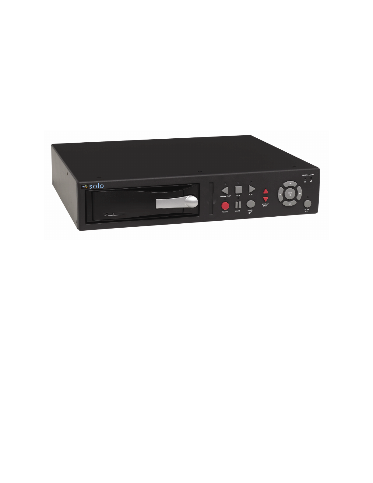
1.1 Product Description
The Vista Solo is a Digital Video Recorder designed to be a direct replacement for a Time Lapse VCR.
Digital Video Recording allows the user to have continuous recording on a removable hard disk,
without the need for replacing or rewinding of videotapes. The Vista Solo provides menu based
search capabilities for recorded events.
1.2 Features
• Single channel VHS Input/Output connection.
• Accepts Single Camera input or a Multiplexed input from most popular multiplexers.
• Compatible with Colour or Monochrome cameras.
• Records up to 50 pictures per second (PAL).
• Continuous Recording in Disk Overwrite mode.
• Removable Hard Drive.
• A simple on-screen menu system.
• Timed recording.
• Programmable Auto Delete Mode.
1.3 Unpacking
Check the package and contents for visible damage. If any components are missing or damaged,
contact the supplier immediately. Do not attempt to use the unit. If, for any reason they must be
returned, the contents must be shipped in the original packaging.
Package Contents
• The Vista Solo unit.
• Power supply and power cord.
• 1 set (2) of Drive keys.
• The Vista Solo user manual.
1.4 Installation Environment
Power: Ensure that the site's AC power is stable and within the rated voltage of the external power
supply. If the site's AC power is likely to have spikes or power dips, use power line conditioning or an
Uninterruptable Power Supply (UPS).
Ventilation: Install the unit in a well-ventilated area. Take note of the locations of the cooling vents in
the unit's enclosure, and ensure that they are not obstructed.
Temperature: Observe the unit's ambient temperature specifications when choosing a location
space. Extremes of heat or cold beyond the specified operating temperature limits may cause the unit
to fail. Do not install the unit on top of other hot equipment.
0150-0267A 1-1 Vista Solo
MENU
2345678
9
Moisture: Do not expose the unit to rain or moisture. Moisture can damage the internal components.
Do not install this unit near sources of water.
Chassis: You can place other equipment on top of the unit if it weighs less than 35 pounds.
1.5 Passwords
Figure 1-1 Passwords
Password Name Function Changeable by user? Password
Advanced Menu
Password
Factory Password
Provides access to the
Advances menu for the
installer.
Restores the unit to the
factory defaults.
Yes: See page 5-5
No
0 0 0 0
8 1 1 1
A password is provided to limit access to the Advanced menu. It is recommended that the default
password be changed after installation is complete. As a security measure, store the password in the
administrator's secured files or in a limited access area. For instructions on entering the Advanced
menu with the password see section 4.6 Main Menu → Advanced Menu on page 4-7.
A password is also provided to return the unit to the factory defaults. For instructions on returning the
unit to the factory defaults, see section 5.6 Advanced Menu → Factory Settings on page 5-5.
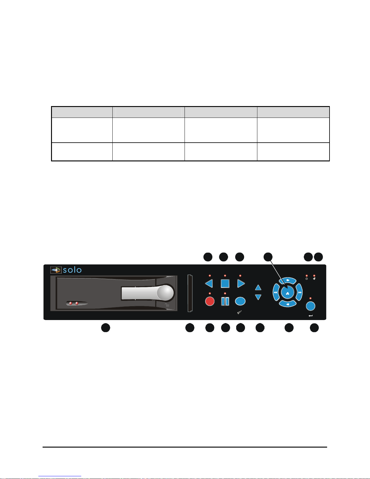
1.6 Front Panel Controls
Figure 1-2 Front Panel
10 11 13 1412
REVERSE PLAY STOP PLAY
POWER ALARM
1
1. Removable Hard Drive: Drives are removable for archival purposes.
2. Card Slot: Not used.
3. Record button: Press this button to begin recording.
4. Pause button: Press this button to pause playback.
5. Search button: Press this button to enter the Search Filters menu.
6. Increase and Decrease Record Speed buttons: Press these buttons to increase or decrease
the Record or Playback speed.
7. Arrow Buttons: Controls Playback speed and menu selections.
8. Enter Button: Confirms selection in menus.
9. Reverse play button: Press this button to playback video in reverse at the normal record speed.
Vista Solo 1-2 0150-0267A
RECORD PAUSE
SEARCH
REC/PLAY
SPEED
ENTER
10. Stop button: Press this button to stop Recording or Playback.
11. Play Forward button: Press this button to playback video at the normal record speed.
12. Menu Button: Provides access to on-screen menus.
13. Power On Indicator: Indicates power is on when LED is lit.
14. Alarm Indicator: Indicates an alarm condition when the LED is lit.
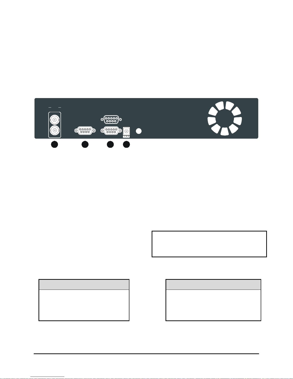
1.7 Back Panel Connections
Figure 1-3 Back Panel
VIDEO
COMP
IN
RS-232 I/O
OUT
1 5
6
9
12V DC
1 2
3
4
1. Video In: Composite video input with BNC style connector.
Video Out: Composite video output with BNC style connector.
2. RS-232 Serial Port: Serial port for Flash Upgrading of software. Also for external control of
unit.
3. I/O Port: For connecting peripheral devices such as alarm devices, alarm relays, or the VEXT
connection.
4. Power Connector: Connect 12 Volt DC external power supply.
Video Input and Output
The unit is equipped with a Composite input and
output. The video input is auto terminating.
Composite Input: 75 Ohm BNC connector.
Composite Output: 75 Ohm BNC connector.
Composite Looping: Yes, while unit is On or Off.
Power Connector
Power Supply Input
Voltage: 240 Volt AC
Tolerance: ±10%
Frequency: 50 Hz
0150-0267A 1-3 Vista Solo
Voltage: 12 Volt DC
Power Supply Output
Power: 35 Watt
Connector: 2.1mm barrel, Center
Positive
RS-232 Serial Port
1
5
6
9
1
5
6
9
Use a Null Modem cable when connecting to a
PC. When connecting to a multiplexer, it may
be necessary to construct a cable using the pinout documentation of the MUX as a guide. See
the pin-out configuration for the Vista Solo
below.
Connector Type: DB-9
Gender (on unit): Male
Cable Required (Connected to PC): Null Modem
Cable Required (Connected to Multiplexer):
Variable, depending on pin-out configuration of
MUX.
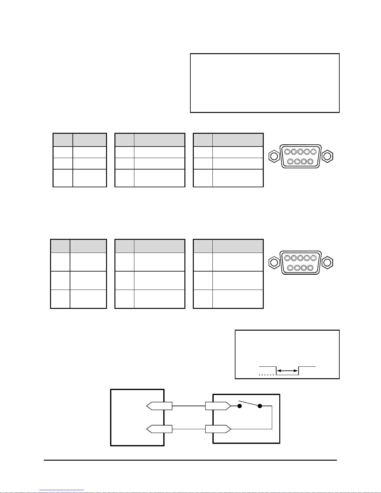
DB-9 Pin Configuration for Serial Port
Pin Use
Pin Use
1 DCD 4 Not Connected 7 RTS
2 RX 5 Ground 8 CTS
3 TX 6 Not Connected 9 Not Connected
Pin Use
DB-9 Connector on
1.8 Accessories I/O Port
The back panel of the unit is equipped with an Accessories Port (DB-9 style connector) for
connecting peripheral devices such as alarm devices, alarm relays, or the VEXT connection.
Do not attempt to wire accessories directly to the DB-9 connector.
Pin Use
Pin Use
Pin Use
RS-232
Back Panel
I/O
1 Alarm In 4
Alarm Record
7 Ground
Reset
2 Alarm Out 5
VEXT Pulse
8 Videoloss Out
Out
3
Record
6 Error Out 9 Disk End Out
Start In
Alarm In
An alarm condition can be activated by an Active Low TTL input
or by relay contact devices such as pressure pads, passive
infrareds, door switches, or other similar devices.
Figure 1-4 Normally Open Relay Alarm Connection
Alarm Input
Ground
Accessories PCB
Pin 1
Pin 7 or 10
Input: Active Low TTL w/ pull-ups
or Normally Open Relay.
High: 5V (12V tolerant)
Low: Ground
Normally Open
(Closes During Alarm)
Typical Alarm Device
Refer to each alarm devices's
manual for specific wiring details.
Minimum Duration: 0.5 Seconds
DB-9 Connector on
Back Panel
Vista Solo 1-4 0150-0267A
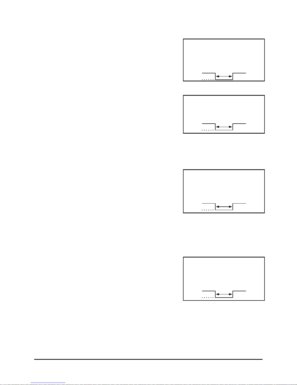
Alarm Out
The Alarm output is activated while the Alarm Input is active.
The Alarm output is only active for the duration of the alarm
event.
Record Start In
Record Start In will place the unit in Record mode when
activated. Compatible with the Disk End Out signal from a
second unit.
Alarm Record Reset
This feature is for future development, and has not yet been implemented.
VEXT Pulse Out
The Video External Pulse connection (VEXT) simplifies
multiplexer operation by automatically synchronizing the
Multiplexer and the Vista Solo.
The Vista Solo sends a VEXT pulse to the Multiplexer indicating
that it is ready to record the next image. The Multiplexer
responds by sending the next image to the Video Input on the
Vista Solo.
The VEXT connection is especially beneficial for units
configured with dual record speeds (Normal and Alarm).
Output: Active Low
High: 12V
Low: Ground
Current Out: 50mA Max
Short Circuit Protected.
Input: Active Low TTL w/ pull-ups
or Normally Open Relay.
High: 5V (12V tolerant)
Low: Ground
Output: Active Low
High: 5V
Low: Ground (0.8V Max)
Current Out: 50mA Max
Short Circuit Protected.
Low for duration of alarm.
Minimum Duration: 0.5 Seconds
Use of the VEXT connection is Highly Recommended when
connecting the unit to a multiplexer.
Error Out
The Error Out signal is activated when the unit experiences any
operational or internal error.
Output: Open Collector
High: Transistor Off
Low: Transistor On
Active When On.
Current Out: 10mA Max
Minimum Duration: 0.5 Seconds
0150-0267A 1-5 Vista Solo
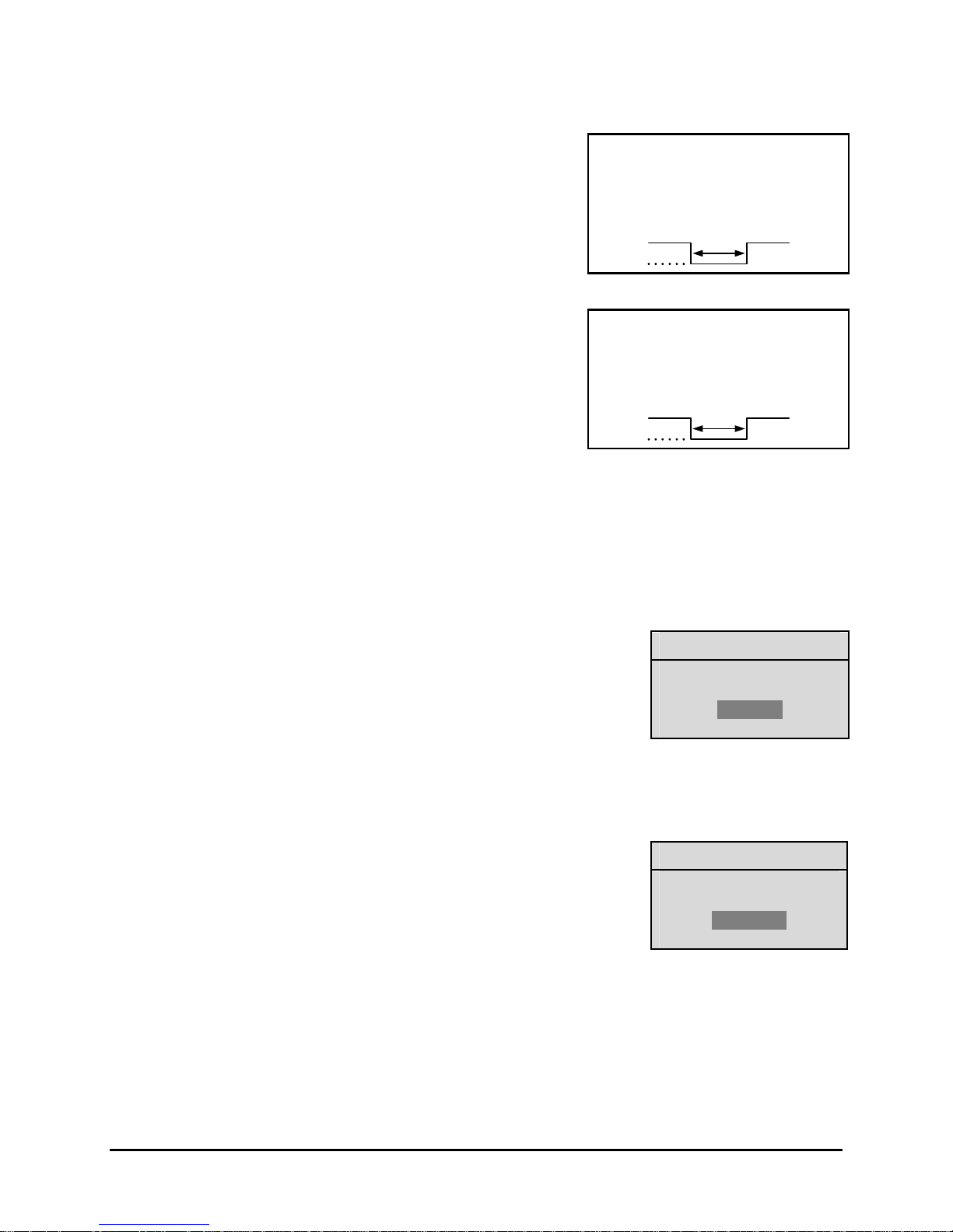
Videoloss Out
The Videoloss Out signal is activated when the unit experiences
videoloss on the video input (Composite).
In the event of videoloss, VIDEOLOSS will be indicated near the
upper left hand corner of the primary monitor.
Output: Open Collector
High: Transistor Off
Low: Transistor On
Active When On.
Current Out: 10mA Max
Minimum Duration: 0.5 Seconds
Disk End Out
The Disk End Out is activated when there is 5 minutes of
recording space left on the hard disk. The Vista Solo must be in
Record mode and set to Continuous Overwrite mode.
Output: Open Collector
High: Transistor Off
Low: Transistor On
Active When On.
Current Out: 10mA Max
Minimum Duration: 0.5 Seconds
1.9 Setting the Time and Date
It is recommended that, as a minimum, the following menu items be configured before using the unit.
For detailed information about using the menu system, see section 3.
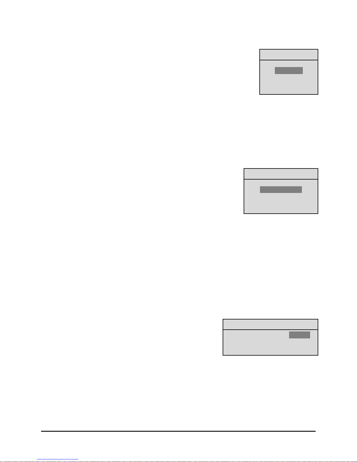
o Main Menu → Time/Date → Set Time Format
To set the Time format, use the Arrow buttons to select the desired
Time format. Format the time as either:
• 12 HOUR
• 24 HOUR
Press the Enter button to confirm the selection and exit the menu.
--OR—
Press the Menu button to exit the menu without making changes.
o Main Menu → Time/Date → Set Date Format
To set the Date format, use the Arrow buttons to select the desired Date
format. Format the Date as either:
• DD/MM/YY
• MM/DD/YY
• YY/MM/DD
Press the Enter button to confirm the selection and exit the menu.
--OR—
Press the Menu button to exit the menu without making changes.
Time Format Setup
Select Format
12 Hour
Date Format Setup
Select Format
MM/DD/YY
Vista Solo 1-6 0150-0267A
o Main Menu → Time/Date → Set Time
To set the Time:
1. With HH MM SS highlighted, press the Enter button. The highlighting
will move to the row of numbers.
2. Enter the time in Hours, Minutes, and Seconds. Use the to change
the values. Use the Arrow buttons to navigate among the three
fields.
3. Press the Enter button to confirm the selection.
4. To Save the changes and Exit the menu: Use the Arrow buttons
to select [OK], then press the Enter button.
--OR--
5. To Exit the menu without making changes: Use the Arrow
buttons to select [CANCEL], then press the Enter button.
o Main Menu → Time/Date → Set Date
To set the Date:
1. With MM DD YY DAY highlighted, press the Enter button. The
highlighting will move to the row of numbers.
2. Enter the date in Months, Days, and Years. Day of the Week
will update automatically. Use the Arrow buttons to change
the values. Use the Arrow buttons to navigate among the
three fields.
Time Setup
HH MM SS
03 05 53
[CANCEL] [OK]
Date Setup
MM DD YY DAY
12 17 00 SUN
[CANCEL] [OK]
3. Press the Enter button to confirm the selection.
4. To Save the changes and Exit the menu: Use the Arrow
buttons to select [OK], then press the Enter button.
--OR--
5. To Exit the menu without making changes: Use the Arrow
buttons to select [CANCEL], then press the Enter button.
1.10 Setting the Alarms
o Main Menu → Alarms
Use this menu to specify:
• Whether an alarm condition will be activated when the
unit detects a signal on the Alarm In connection.
• Whether the internal buzzer is activated during an
alarm condition.
Alarms Menu
Hardwire Alarm : Enable
Alarm Buzzer : Enable
[CANCEL] [OK]
0150-0267A 1-7 Vista Solo
345
3
To configure the alarm settings:
1. Use the Arrow buttons to navigate among the fields.
2. Use the Arrow buttons to change the values of the
highlighted fields.
3. To Save the changes and Exit the menu: Use the
Arrow buttons to select [OK], then press the Enter
button.
--OR--
4. To Exit the menu without making changes: Use the
Arrow buttons to select [CANCEL], then press the
Enter button.
Hardwire Alarm : Enable
Alarm Buzzer : Enable
[CANCEL] [OK]
Alarms Menu
1.11 The Removable Hard Drive
The Vista Solo has a built-in removable hard drive that comes in 40, 80, and 160 GB models. The hard
drive is hot swappable; meaning the Vista Solo need not be powered down before drive removal.
However, it is recommended that the drive not be removed during any drive activity (read/writes).
Whatever state (recording, playback) the drive is operating in, when it is removed, is the same state it will
start up in when reinstalled.
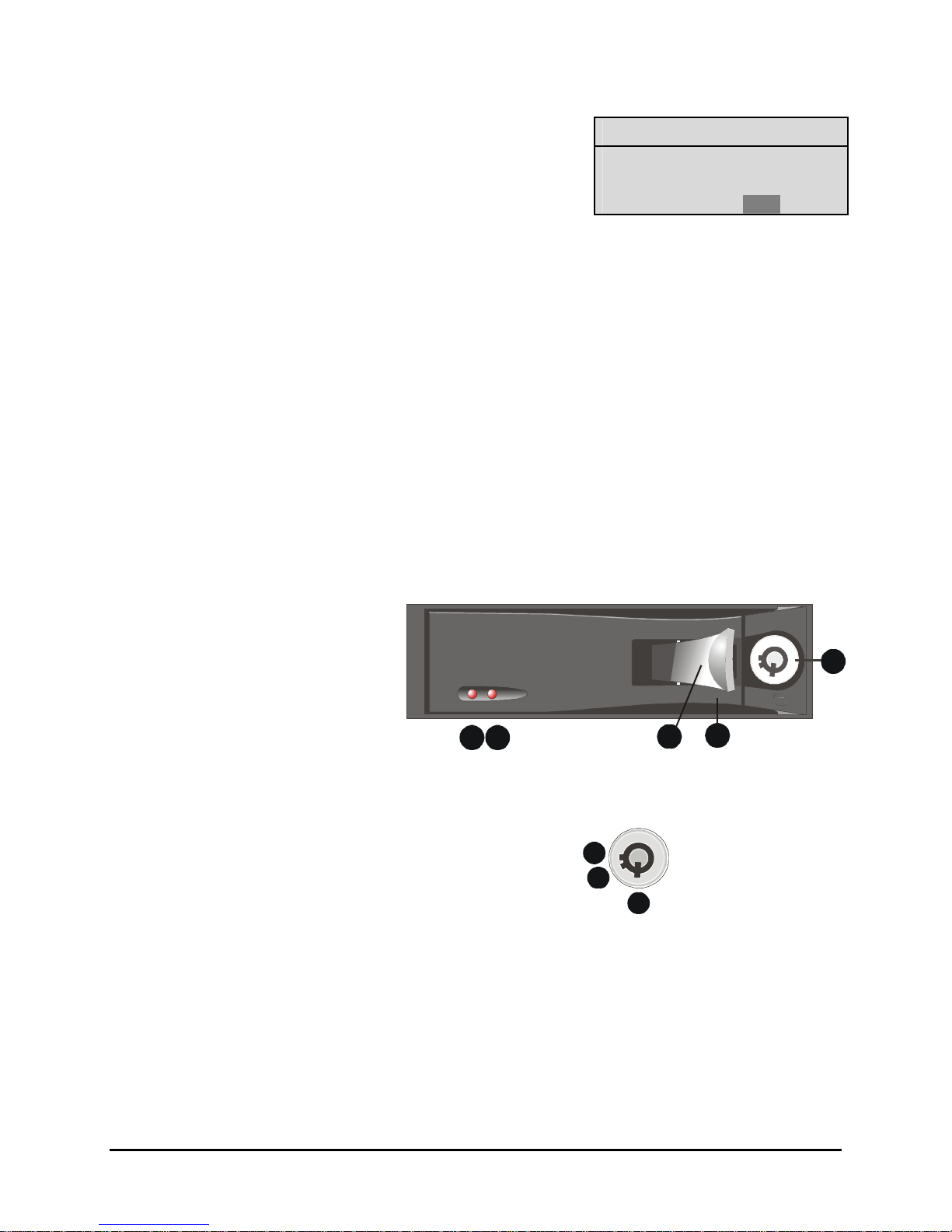
Hard Drive Front Panel
1. Hard Drive Activity LED, Amber.
2. Power Indicator, Green.
3. Active Handle (Shown Open).
4. Handle.
5. Key Lock.
Key Lock
1. Power On. Drive Locked
2. Power Off. Drive Locked.
3. Power Off. Drive Unlocked. (Shown)
1 2
1
2
Vista Solo 1-8 0150-0267A
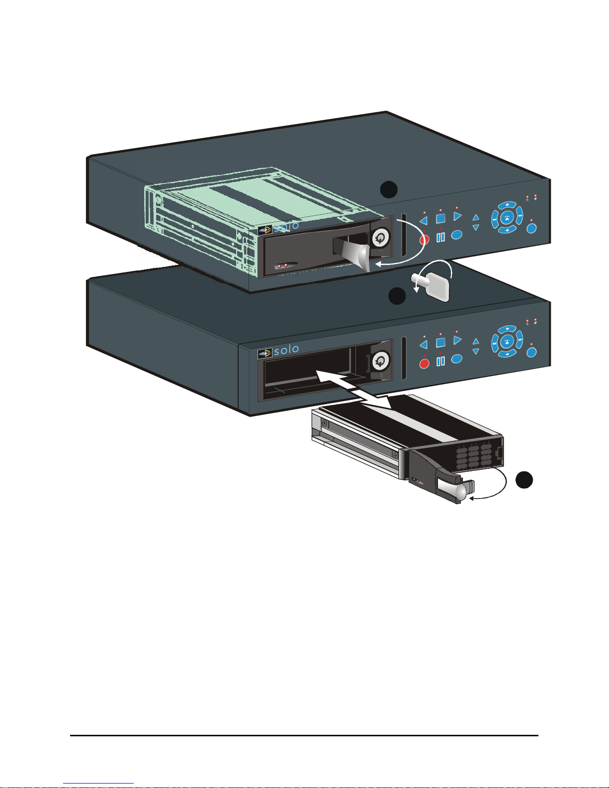
1.12 Removing the Hard Drive
213
1. Pull the active handle outward.
2. Use the key provided and place the key lock in position 3
shown above (rotate counter clockwise).
3. Pull the handle outward and slide the carrier body away from the cartridge frame.
To reinsert the drive perform the above steps in reverse. The Vista Solo will reset when the
drive is installed.
0150-0267A 1-9 Vista Solo

 Loading...