

Architectural Series
LED Retrofit Kit
INSTALLATION INSTRUCTIONS
WARNING – RISK OF FIRE OR ELECTRIC SHOCK. INSTALL THIS KIT ONLY IN THE LUMINAIRES
THAT HAS THE CONSTRUCTION FEATURES AND DIMENSIONS SHOWN IN THE PHOTOGRAPHS
AND/OR DRAWINGS AND WHERE THE INPUT RATING OF THE RETROFIT KIT DOES NOT EXCEED
THE INPUT RATING OF THE LUMINAIRE.
AVERTISSEMENT – RISQUE D’INCENDIE OU DE CHOC ÉLECTRIQUE. N’INSTALLER CE NÉCESSAIRE
QUE DANS LES LUMINAIRES DONT LES CARACTÉRISTIQUES DE CONSTRUCTION ET LES
DIMENSIONS SONT CONFORME À CELLES ILLUSTRÉES DANS LES PHOTOS ET/OU LES DESSINS
ET DONT LA PUISSANCE D’ENTRÉE NOMINALE DU NÉCESSAIRE DE MODERNISATION NE
DÉPASSE PAS CELLE DU LUMINAIRE.
___________________________________________________________________________________________
THIS RETROFIT KIT IS ACCEPTED AS A COMPONENT OF A LUMINAIRE WHERE THE SUITABILITY
OF THE COMBINATION SHALL BE DETERMINED BY AUTHORITIES HAVING JURISDICTION. (S24-L5)
LE NÉCESSAIRE DE MODERNISATION EST ACCEPTÉ À TITRE DE COMPOSANT D’UN LUMINAIRE
LORSQUE LA PERTINENCE DE LA COMBINAISON DOIT ËTRE DÉTERMINÉE PAR PAR LES
AUTORITÉS COMPÉTENTES
___________________________________________________________________________________________
RK91
DO NOT MAKE OR ALTER ANY OPEN HOLES IN AN ENCLOSURE OF WIRING OR ELECTRICAL
COMPONENTS DURING KIT INSTALLATION.
IL EST INTERDIT DE FAIRE OU DE MODIFIER UNE OUVERTURE DANS UN BOÎTIER DE CÂBLAGE OU
DE COMPOSANTS ÉLECTRIQUES AU COURS DE L’INSTALLATION DU NÉCESSAIRE. (S24-L5)
___________________________________________________________________________________________
WARNING – RISK OF FIRE OR ELECTRIC SHOCK. INSTALLATION OF THIS RETROFIT ASSEMBLY
REQUIRES A PERSON FAMILIAR WITH THE CONSTRUCTION AND OPERATION OF THE
LUMINAIRE’S ELECTRICAL SYSTEM AND THE HAZARD INVOLVED. IF NOT QUALIFIED, DO NOT
ATTEMPT INSTALLATION. CONTACT A QUALIFIED PERSON.
AVERTISSEMENT – RISQUE D’INCENDIE OU DE CHOC ÉLECTRIQUE. L’INSTALLATION DE CE
NÉCESSAIRE DE MODERNISATION EXIGE UNE PERSONNE FAMILIÈRE AVEC LA CONSTRUCTION
ET LE FONCTIONNEMENT DU SYSTÈME ÉLECTRIQUE DU LUMINAIRE ET DES RISQUES ASSOCIÉS.
TOUTE PERSONNE QUI N’EST PAS QUALIFIÉE NE DOIT FAIRE AUCUNE TENTATIVE
D’INSTALLATION ET DOIT CONTACTER UNE PERSONNE QUALIFIÉE.
Vista Professional Outdoor Lighting reserves the right to modify the design and/or construction of the fixture shown without further notification.
1625 Surveyor Avenue • Simi Valley, CA 93063 • (805) 527-0987 • (800) 766-VISTA (8478)
FAX: (888) 670-VISTA (8478) • email@vistapro.com • www.vistapro.com
1/4
RK91
POWER MODULE
remove and discard
LAMP MODULE
remove and discard
DOOR ASSEMBLY
remove and discard
J-BOX COVER
W/ SCREWS & SEAL
remove and retain
HOUSING
fixed and burried
OLD CORD SEAL
& OLD WIRE NUTS
remove and discard
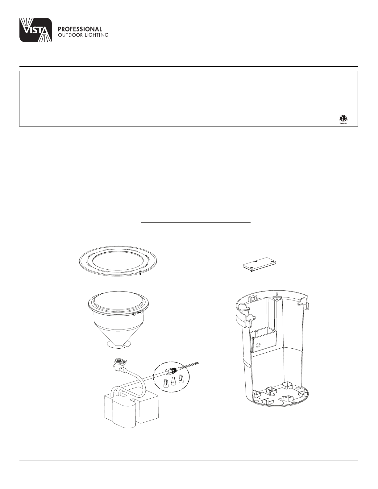
Disassembly of Existing Fixture
Architectural Series
LED Retrofit Kit
INSTALLATION INSTRUCTIONS
IMPORTANT NOTE:
• Retrofit Kit must be installed and grounded in accordance with the National Electrical Code (NEC) and local codes.
• All conduit entries must be sealed from moisture. Use appropriate sealing material on conduit fittings and conduit closure plugs.
• Retrofit Kit is wet location listed and suitable for mounting in Hydrel® Model 9100 Series in-grade rough-in sections.
• Suitable for all types of construction including poured concrete construction and in soil applications.
• Suitable for through wiring: Max. of (4) No. 12 AWG conductors (plus ground) rated for 90°C.
MAINTENANCE: To assure proper operation and efficiency and to prevent luminaire overheating, lens must be kept clean and free of dirt, dust, leaves, trash and mineral
deposits from water. A regular schedule maintenance program is recommended.
NOTE: Save these instructions for future reference.
NOTICE: To prevent electric shock, turn main power off at circuit breaker. DO NOT INSTALL RETROFIT WHILE SYSTEM IS ENERGIZED.
Disassembly of Existing Fixture:
1. Remove and discard existing door assembly.
2. Remove and discard existing Lamp Module and any associated bracketry and hardware by lifting the Lamp Module out of the Housing and unplugging
it from the Power Module.
3. Remove Power Module from Housing and set on grade outside of fixture.
4. Remove J-Box Cover and disconnect the wiring splices within the J-Box. Retain J-Box Cover with gasket and screws as these will be reused later.
Inspect components for damage and replace any damaged parts prior to installation of the Reftrofit Kit. Discard the old Wire-Nuts.
5. Remove the Cord Seal from the J-Box. Discard the Power Module along with the old Cord Seal.
Vista Professional Outdoor Lighting reserves the right to modify the design and/or construction of the fixture shown without further notification.
1625 Surveyor Avenue • Simi Valley, CA 93063 • (805) 527-0987 • (800) 766-VISTA (8478)
FAX: (888) 670-VISTA (8478) • email@vistapro.com • www.vistapro.com
2/4

Assembly of Retrofit Kit within the Hydrel® Fixture
J-Box
(sectioned for clarity)
New Silicone Filled Wire-Nuts
-3 EA for Non Dimming & Triac Dimming
-5 EA for 0-10V Dimming
(connects Supply Conductors to Retrofit LED
Module Cable conductors (Load)
J-Box Cover
Supply Conductors
(within J-Box)
Cable Jacket extends
pasr Cord Seal 1"-2"
New Cord Seal
Door Catch Receiver
Door Catch
Captive Door Screw
Route Retrofit LED Module Cable
through top side of Stainless Trim Ring (STR)
(if STR accessory is specified)
Module Support
(6 PLCS)
Retrofit LED Module Cable (Load)
-3 Conductor for Non Dimming
& Triac Dimming
-5 Conductor for 0-10V Dimming
Housing
(fixed and buried)
Stainless Trim Ring (STR)
(optional accessory)
Exploded Assembly
Door Screw Location
(1 PLC)
Module Logo
(centered between Door Screw
and Door Catch locations)
Retrofit LED Module
Completed Assembly
RK91 Retrofit Kit consists of:
one (1) Retrofit LED Module, one (1) Cord Seal and five (5) Silicone Filled Wire-Nuts.
ASSEMBLY OF RETROFIT KIT WITHIN FIXTURE:
1. Firmly tighten newly provided Cord Seal into J-Box ensuring a liquid tight fitting.
NOTE: If a Stainless Trim Ring (STR) accessory is to be used, route the free end (Load) of Retrofit LED Module Cable through the top side of the STR
before continuing to step 2.
2. Route the free end (Load) of Retrofit LED Module Cable through the new Cord Seal such that the Cable Jacket extends past the Cord Seal 1”- 2” and that
the splices will terminate within the J-Box. Firmly tighten the nut on the Cord Seal ensuring a liquid tight fitting.
3. Using the provided Silicone Filled Wire-Nuts, connect the supply conductors within the J-Box to the load conductors of the Retrofit LED Module.
NOTE: See sheet 3 for wiring diagrams of both (A) Standard 3 Wire Electrical Connections and (B) Optional 5 Wire 0-10V Dimming Electrical Connections.
4. Re-install junction box cover and gasket making sure that none of the splices are pinched within the seal. Tighten to ensure proper sealing.
NOTE: If a Stainless Trim Ring (STR) accessory is to be used, set the STR inside the top lip of the housing before continuing to step 5.
5. Place the LED Retrofit Module within the Housing by inserting the Module Door Catch into the Door Catch Receiver of the Housing and onto the six (6)
Module Supports. Align the Captive Door Screw of the Module with the mating fastener of the Housing. Snug the captive screw to secure the Module
(do not overtighten).
6. Supply power to the luminaire and check for proper operation.
Hydrel® is a registered Trade Mark of Acuity Brands.
Vista Professional Outdoor Lighting reserves the right to modify the design and/or construction of the fixture shown without further notification.
1625 Surveyor Avenue • Simi Valley, CA 93063 • (805) 527-0987 • (800) 766-VISTA (8478)
FAX: (888) 670-VISTA (8478) • email@vistapro.com • www.vistapro.com
3/4

WIRING DIAGRAMS:
(A) STANDARD 3 WIRE ELECTRICAL CONNECTIONS
SUPPLY CONDUCTORS
(120-277V LINE VOLTAGE)
120-277V SUPPLY (LINE)
SUPPLY (NEUTRAL)
SUPPLY (GROUND)
SPLICE
(within J-Box)
LOAD (BLACK)
LOAD (WHITE)
LOAD (GREEN)
Retrofit LED Module Cable (LOAD)
(B) OPTIONAL 5 WIRE 0-10V DIMMING ELECTRICAL CONNECTIONS
SPLICE
(within J-Box)
LOAD (BLACK)
SUPPLY CONDUCTORS
(120-277V LINE VOLTAGE)
DIMMING CONDUCTORS
(0-10V LOW VOLTAGE)
120-277V SUPPLY (LINE)
SUPPLY (NEUTRAL)
SUPPLY (GROUND)
(+)
DIMMING
DIMMING
(-)
LOAD (WHITE)
LOAD (GREEN)
DIMMING LOAD (RED)
DIMMING LOAD (ORANGE)
Retrofit LED Module Cable (LOAD)
Vista Professional Outdoor Lighting reserves the right to modify the design and/or construction of the fixture shown without further notification.
1625 Surveyor Avenue • Simi Valley, CA 93063 • (805) 527-0987 • (800) 766-VISTA (8478)
FAX: (888) 670-VISTA (8478) • email@vistapro.com • www.vistapro.com
4/4
RK91 12.16
 Loading...