

Page 1

PowerMaxComplete User Gui de
Table of Contents
Quick Guide To Primary Alarm Control
Operations...........................................................2
Contact list form..................................................2
Luminous Indicator Signals...............................2
Siren Signals.......................................................3
Useful Hints For PowerMa xComplete Users.3
1. Introduction.................................................... 4
Overview..............................................................4
System Features ................................................5
Terms of the Trade.............................................6
Control Pushbuttons...........................................6
Multi-Function Transmitter ................................7
Voice Announcement s.......................................7
Screen Saver Option..........................................7
2. Securing The Protected Site......................... 8
Security-Related Pushbuttons ..........................8
Preparing to Arm ................................................8
Arming ‘AWAY’ ...................................................8
Arming ‘HOME’...................................................8
Switching from ‘HOME’ to ‘AWAY’...................8
Switching from ‘AWAY’ to ‘HOME’...................9
Arming ‘Instant’ ...................................................9
Forced Arming ....................................................9
Arming in the Latchk ey M ode .........................10
Initiating a Panic Alarm....................................10
Initiating Fire Alarm..........................................10
Initiating Emergency Alarm.............................10
Disarming and Stopping Alarms.....................10
Siren Behavior ..................................................11
3. Speech And Sound Control......................... 12
Speech & Sound Cont. Push-buttons............12
Adjusting the Speech Volume.........................12
Voice ON/OFF ..................................................12
Recording a Message......................................12
Message Playback ...........................................13
Chime ON/OFF.................................................13
4. Electrical Appliance Control....................... 14
Control Options and Pushbuttons ..................14
Automatic ON/OFF Control.............................14
5. Reading Alarm Memory And Trouble Data. 15
Reviewing Alarm/Tamp er Memory.................15
Reviewing Trouble Information.......................15
Reviewing Memory & Troubles at the Same
Time ...................................................................16
Correcting Trouble Si tuations .........................16
6. Special Functions .........................................17
Looking after People Left at Home................ 17
Emergency Calls for Help............................... 17
Remote Control by Telephone....................... 17
Reporting to Private Telephone..................... 18
Remote Control by SMS................................. 19
Reporting by SMS............................................ 19
Reporting Messages to a Pager.................... 20
Conducting a Walk Test.................................. 20
7. User Settings................................................21
What are the Setti ngs You Need?................. 21
Entering the User Sett ings Menu................... 21
Bypassing Zones ............................................. 22
Reviewing the Bypass ed Zone List............... 22
Recalling the Last Bypass Scheme ............... 23
Programming 4 Telep hone Numbers............ 23
Setting the User Codes................................... 23
Enrolling Keyfob Transmitters........................ 25
Deleting Keyfob................................................ 26
Enrolling Proximity Tags (optional)................ 26
Deleting Proximity Tags.................................. 26
Setting the Voice Opti ons ............................... 27
Automatic Arming Option................................ 27
Setting Arming Time........................................ 27
Enabling the Squawk Option.......................... 27
Setting Time and Time Form at ...................... 28
Setting the Date and Date Format................. 28
Scheduler Functi on.......................................... 29
Installer Mode................................................... 29
8. Reading The Event Log................................30
Event Log Descript ion..................................... 30
Reading Procedure.......................................... 30
9. Maintenance..................................................31
Replacing the Backup Battery........................ 31
Replacing Wireless Devices Batteries.......... 31
Periodic Testing............................................... 32
Cleaning the Control Pa nel ............................ 32
10. Performance Limits....................................33
APPENDIX A. GLOSSARY................................ 34
APPENDIX B. HOME FIRE ESCAPE PLANNING
........................................................................36
D-300886 1
Page 2
Quick Guide To Primary A larm Control Operations
Quick Guide To Primary A larm Control Operations
Quick Guide To Primary A larm Control OperationsQuick Guide To Primary A larm Control Operations
QUICK REFERENCE TO PRIMARY ALARM CONTROL OPERATIONS
Arming AWAY ........................................
Arming AWAY-IN S TANT ........................
Arming HOME ........................................
Arming HOME-INSTANT .......................
Arming AWAY-L ATCHKEY ...................
For c e Arm ing AWAY (system not ready)
Force Arming HOME (system not ready)
Disarming and stopping alarms............
* The factory default master user code is 1 1 1 1. The code is not required if quick arming
installer. Change the factory default code to a secret code without delay (see section 7)
Contact lis t form
Contact lis t form
Contact lis t formContact lis t form
+
+
+
+
+
+
+
+
+ [Code]*
+ [Code]* +
+ [Code]*
+ [Code]* +
+ [Code]* +
+ [Code]* +
+ [Code]* +
+ [Code]
+
+
+
+
+
(to silence the prot est buzz)
(to silence the protest buzz)
has been permitted by the
Dear Customer,
Thank you for choosing PowerMaxComplete, a
highly advanced wireless alarm control system
produced by Visonic Ltd.
Please note below th e installer's telephone number
to facilitat e obtaining assis tance.
Company Name: ___________________ _________
Telephone Number: _________________ _________
Person to Contact: __________________ _________
Also please make s ure that you have the name a nd
telephone number of the centr al station yo ur system
will report to. If you ever call t he central station to ask
questions, you s hould be able to c ome up with your
"ACCOUNT NUMBER" used to identify your alarm
system to the cent ral station. Obtain this information
from your installer and write it.
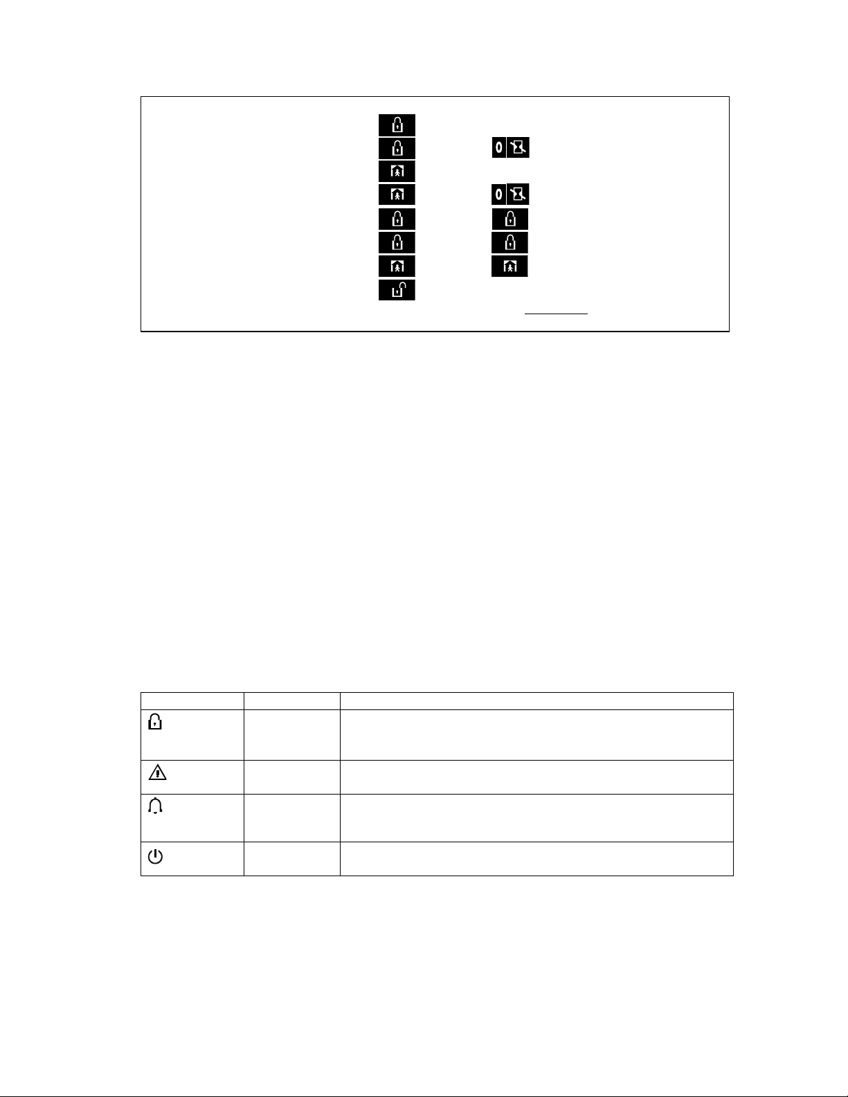
Luminous Indicator Signals
Luminous Indicator Signals
Luminous Indicator SignalsLuminous Indicator Signals
Indicator Behavior Significance
(red)
(orange)
(green)
(green)
Lights steadily
Flashes
No light
Lights steadily
No light
Lights steadily
No light
Lights steadily
No light
The system is in the ar m ed state (AWAY MODE)
The system is in the arm ed state (HOME MODE)
The system is presently in the disarmed state
A state of trouble is presently being detected
No trouble - all is well
The chime function is active - chime zones will chime when disturbed.
The chime function is inactive - chime zones will not chime when
disturbed.
AC power is supplied to the control panel
The system is operating on backup battery power
Monitoring Station’s Name _____________________
Telephone Number: _________________ _________
My Account Number: _________________________
If your system was set by the installer to contact
private telephone numbers, note down the 4
telephone numbers that your installer programmed to
be called:
Phone No. 1: ______________________ _________
Phone No. 2: ______________________ _________
Phone No. 3: ______________________ _________
Phone No. 4: ______________________ _________
2 D-300886
Page 3
Siren Sign als
Siren Sign als
Siren Sign alsSiren Sign als
Alarm Type Graphic Representation of Signal
Burglar / 24
hour/ Panic
Fire – – – – – – – – – – – – ................. ON - ON - ON - pause - ON - ON - ON - pause .....
Test* –– (both external and internal sirens) ON for 2 seconds (once)
* Supplementary use only.
Useful Hints For PowerMaxComplete Users
Useful Hints For PowerMaxComplete Users
Useful Hints For PowerMaxComplete UsersUseful Hints For PowerMaxComplete Users
Stopping an alarm: When the alarm sounds -
press the DISARM (
transmitter or press
enter your access code (1 1 1 1 by default).
Stopping trouble beeps: When trouble oc curs in
the system, the TROUBLE in dicat or on t he fr ont panel
will light, and a sequence of 3 beeps will sound onc e
per minute. If you do not wish to eli minate the troubl e
immediately and the b eeps ar e bothersome, press t he
DISARM (
press
access code (1 1 1 1 by default). This will silence the
buzzer for 4 hours , after which the trouble beeps will
resume sounding. Be advised, however, that in any
case the trouble beeps are silenced during night
hours.
Perimeter and inter ior zones versu s 24-hour
zones: Most of the protec tion s ens ors in your syst em
are linked to perimeter and interior zones. These
zones trigger alarms while the s ys tem is i n the armed
state and do not tr igger alar ms while t he syst em is in
the disarmed state. Other sensors are linked to 24hour zones which trigger alarms irrespective of
arming/disarming.
Arming while perimeter zones are not
secured (doors and/or windows are open):
Your display will read “NOT READY” if a protected
door or window is open. Yo u can find out which zone
is “not ready” by c licking the
can eliminate the probl em by closing the door /window
or by performing "For ced arming" (zone deactivation)
if this option was ena bled by the system installer. In
case you intention ally choos e to bypas s a zone, lea ve
the door or window open an d arm the sys tem (a voice
message will announce that ” Forced Arming” is under
way - not applic able in PowerMaxCompl ete that does
not have VOICE option).
Bypassed zones will not be protected during one
arming period.
––––––––––––––––––––––––––––––– ON continuously
) button on your key-ring
) button on your key-ring transmitter, or
on the keypad and then enter your
on the keypad and th en
button. You
Verbal Description of Signal
Gaining access to 24-hour zones: If you wish
to access a sensor defined as a 24-hour zone without
causing an alarm:
• Click
NORMAL MODE.
• Click
USER SETTINGS.
• Click
CODE ___.
Key your secret 4-digit <User Code> - the buzzer will
play the “happy tune” (- - - ––––).
You have 4 minutes dur ing which the 24-hour sensor
can be opened and accessed. When the 4 minutes
are up, the system will automatically revert to the
normal mode.
Canceling accidental alarms: Upon alarm, the
internal sounder i s act ivated f irst f or a limi ted peri od of
time (set by the installer). Then the external siren
starts and the event is reported to the central
monitoring stat ion. If you acc identally caus e an alarm,
you may simply disar m the s ystem befor e the exter nal
siren starts - the alarm will not be repor ted
If you cause an alarm accidentally and the external
siren has already started - you can still disarm the
system within a time limit set by the installer (1 to 15
minutes, as desired). If you m anage to disarm on time,
a CANCEL ALARM message will be automatically
sent to the centr al monitoring station.
Failing to exit befor e the exit delay expi res:
If you exit the protected site after the exit delay expires
(the exit delay beeps stop), the system will interpret
this as if you just entered. The entry d elay countd own
will begin and the entry delay beeps will sound. To
prevent an alarm, yo u must disarm the system befor e
the entry delay expires.
Unauthorized entry took place while you
were away: If you he ar alarm sirens when you are
about to re-enter the premises, and lights which
should be off are on - an intr uder may s ti ll be insi de or
another event may have occ urred. Do n ot c onfront t he
intruder - remain outside and call the emergency
services.
- the display will read:
again - the display will read:
- the display will read: ENTER
.
D-300886 3
Page 4
INTRODUCTION
1. Introduction
1. Introduction
1. Introduction1. Introduction
Overview
Overview
OverviewOverview
The PowerMaxComplete i s a wireless alarm control
system that provi des protection agai nst burglary, f ire
and tampering. In addition, it can be used to control a
light or an el ectrical appl iance wi thin your h ousehold
and/or to monitor the activity of disabled or elderly
people left at hom e. Status informat ion is presented
visually and ver bally, and in most c ases a recorded
voice prompts you to take correct action - not
applicable in Power MaxComplet e that does not have
VOICE option.
The PowerMaxComplete is governed by a control
panel (Figure 1) designed to collect data from
various sensors that are strategically located within
and along the per imeter of t he protec ted site ( Figure
2).
In the disarmed state, the system pr ovides you wi th
visual and verbal status informat ion, and initiates an
alarm if smok e is detected or upon di sturbance in a
24-hour zone (a zone which is active 24-hours a
day).
In the armed state, the system will initiate an alarm
upon detection of disturbance in any one of the
armed zones.
You will need a 4-digit security code to master the
system (code 0000 is disallowed), and you can
authorize 7 other persons to use the system by
providing them with their own security codes.
Moreover, you can o btain up to 8 multi -function keyring transmitters and proximity tags that will allow
you and other users to easily control major functions.
Proximity tags enable authorized people to enter
restricted ar eas. Present ing valid pr oximity t ag, while
the system is arm ed, causes the system to disar m.
Presenting valid proximity tag, while the system is
disarmed, causes the system to be armed in AWAY
(optional HOME) mode.
The system identifies a wide range of events alarms, attempt s to tamper with s ensors and s everal
types of trouble. Events are automatically reported
via the public tel ephone network or GSM net work to
central monitoring stations (in digital form) and to
private telephones (in plain language and/or SMS
messages). The per son rec eivi ng s uch a mes sage i s
expected to investigate the event and act
accordingly.
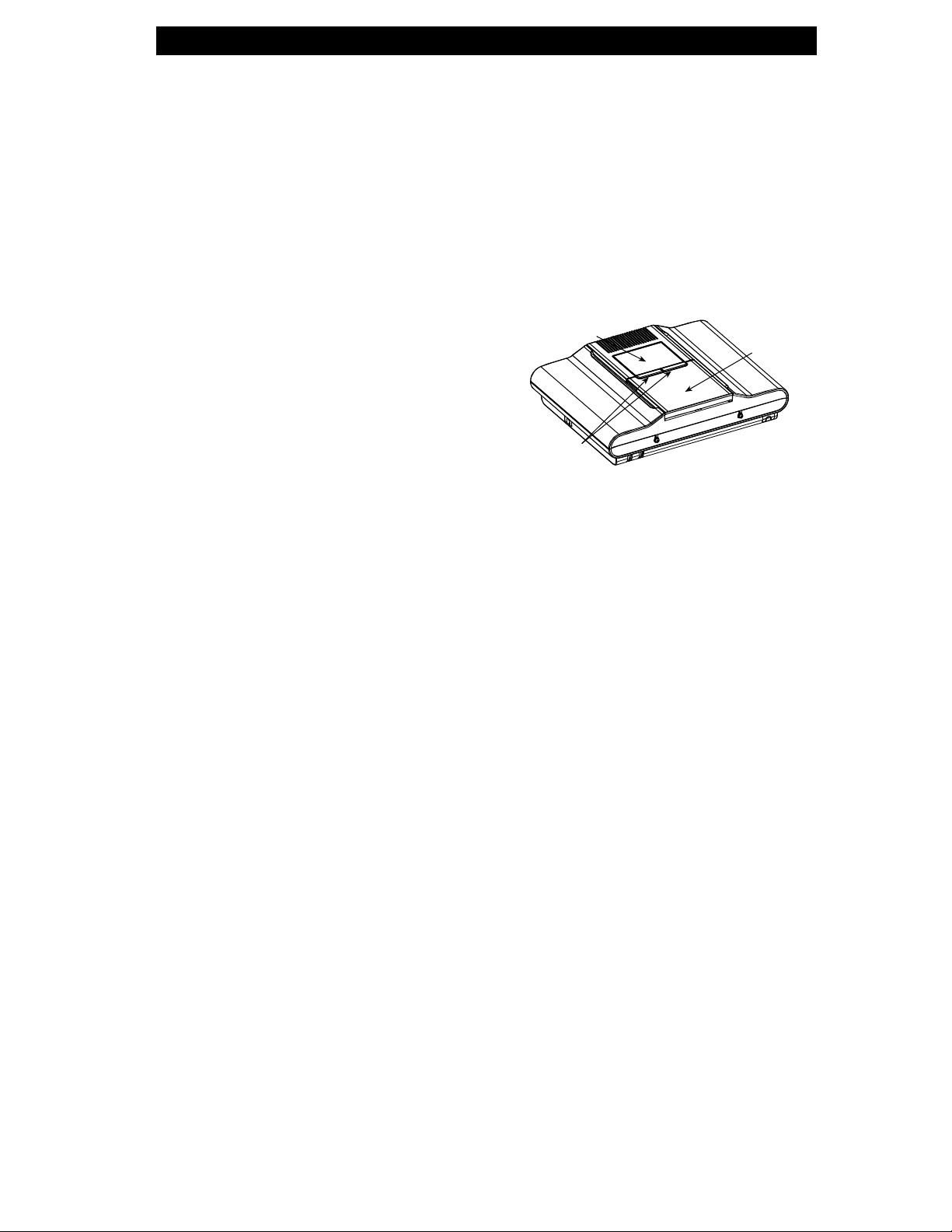
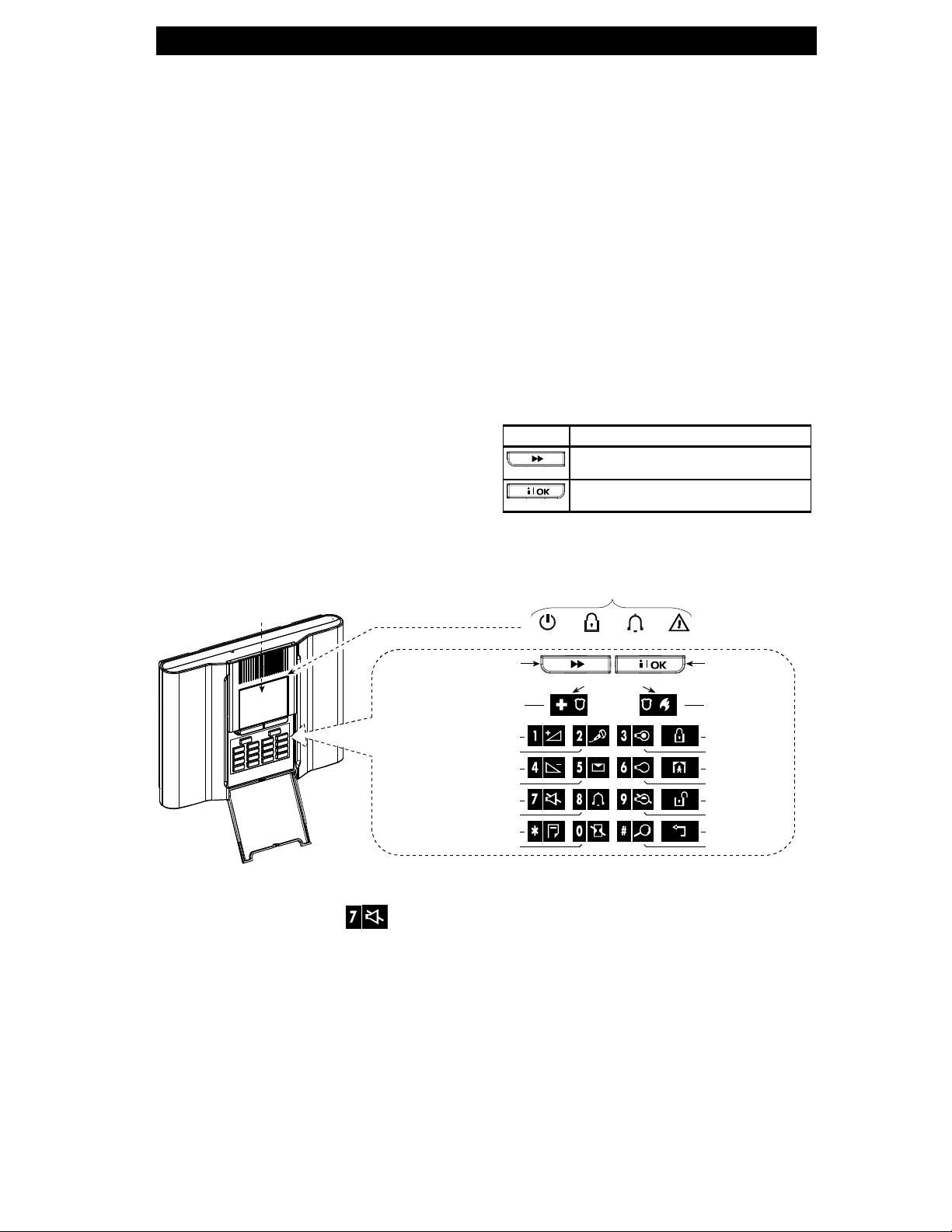
DISPLAY
CONTROL
KEYS
Figure 1. Control Panel wit h Covers Closed
IMPORTANT! All you need t o know to secure your
premises can be found in Chapter 2 of this manual.
If you are not familiar with some of the terms used
here, refer to Appendix A at the end of this guide.
KEYPAD
COVER
(CLOSED)
4 D-300886
Page 5
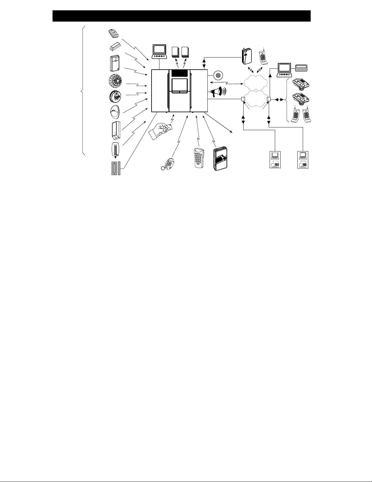
WIRELESS
DETECTORS
(UP TO 28 UNITS)
INSTAL L ED IN
THE PROTECTED
PREMISES
EMERGENCY
PENDANT
TRANSMITTERS
DOOR OR
WINDOW
OPEN/CLOSE
DETECTOR
UNIVERSAL
PERIMETER
PROTECTION
DETECTOR
SMOKE
DETECTOR
CO GAS
DETECTOR
MOTION
DETECTOR
FLOOD
DETECTOR
GAS
DETECTOR
UP TO 2
HARD WIRED
DETECTORS
LOCAL
COMPUTER
(OPTION)
UP TO 8
PROXIMITY
(optional)
WIRELESS
TAGS
UP TO 8 KEYFOB
TRANSMITTERS
SIRENS
UP TO 8 WIRELESS
REMOTE
COMMANDERS
SITE INTERNAL
SIREN OR
STROBE
TEL. LINE
Figure 2. System Configuration
EXTERNAL
GSM UNIT
(optional)
SITE
EXTERNAL
SIRENS
PGM OUTPUT FOR
CONTROLL I NG DE VI C ES
BY VARIOUS FACTORS
AS PROGRAMMED
BY THE INSTALLER
UP TO TWO
2-WAY KEYPADS
INTRODUCTION
CEL. TEL
PAGER COMPANY
GSM
NETWORK
PUBLIC
SWITCHING
TELEPHONE
NETWORK
LOCAL
EXCHANGE
COMPUTER
4 PRIVATE
TELE-
PHONES
CENTRAL MONITORING
PAGER
STATIONS
System Featur es
System Featur es
System Featur esSyst em Fe at ures
Your PowerMaxComplete offers a large number of
unique features:
• 30 zones: Each protected zone is identified by
number and by name (ask your installer to assign
names to your zo ne s).
• Multiple arming modes: AWAY, H OME, AWA Y-
INSTANT, HOME-INSTANT, LATCHKEY and
BYPASS.
• Liquid crystal display (LCD): Plain-language
status information and prompts are displayed on
the front panel in lar ge, clear letters.
• Real-time cl ock: The present tim e is visible on the
display.
• Various reporting destinations: Events are
reported automatically to central monitoring
stations, private telephones of your choice and
even to a pager.
• Selective repor ting: Your installer can determine
what type of event will be reported to which
destination.
• Latchk e y mod e: An automatic “Latchkey” message
is sent to chosen telephones if the system is
disarmed by a “latchkey” user (a junior family
member, for instance).
• Spoken announcements and instructions (not
applicable in PowerMaxComplete that does not
have VOICE option): Status- dependent, prerecorded verbal messages are heard over the
built-in loudspeaker (if the voice prompts are
enabled - see chapter 7).
• Message exchange (not applicable in
PowerMaxComplete that does not have VOICE
option): Before leaving the premises, you may
record a short ver bal message for other users of
the system who may ar rive later . Upon arri val, you
can listen to verbal messages left by others for
you.
• Keypad and wireless control: Full control from
the keypad; major functions can be carried out by
pressing buttons on hand-held miniature
transmitters.
D-300886 5
Page 6
INTRODUCTION
• Access from remote telephones: You may
access the PowerMaxComplete from a remote
telephone and Arm/Disarm it or receive system
status information.
• Numerical ke ys serve as funct ion keys: In the
disarmed state, numeric al k eys are us ed t o contr ol
various system functions. A simple icon on each
key identifies the task of that key.
• PGM remote control: Gate control mechanisms,
courtesy lights and various other devices can be
switched on and off via a special PGM
(programmabl e) o utp ut. Y our i nstal ler wi ll deter mi ne
the control means, in accordance with your needs.
• Data retrieval: You can obtain status information,
trouble information and review memorized alarm
events - visually and verbally.
• Looking after elderly, physically handicapped
and infirm individuals: The system can be
programmed t o monitor act ivity wit hin the protec ted
area and send out a n alert message if the per son
under surveillance re mains still for too long.
• Distress calls: Miniature pushbutton transmitters
dealt out to specific individuals may be used for
sending emergency calls for help.
• Disarming under duress: If a user is forcibly
compelled to disarm the system, he can use a
special code that disarms the system apparently as
usual, but s ends a si lent alarm to t he ce ntr al st ati on
(see chapter 2).
DISPLAY
EMERGENCY
(Hold for 2 sec.)
• System supervision: All wireless detectors and
wireless comma nder s wit hin th e pr otect ed si te se nd
periodic supervision messages. If such a message
is overdue, the PowerMaxComplete displays an
‘inactivity’ trouble message. Your installer can
disable this feature if so desired.
• Battery supervision: You do not have to worry
about ‘dead’ batteries. The PowerMaxComplete
displays a ‘Low Battery’ message whenever a
battery in a wirel ess devi ce is found to be n ear the
end of its useful life.
Terms of the T rade
Terms of the T rade
Terms of the T radeTerms of the T rade
Better underst anding of your syst em is assured if you
take time to read the defi nitions in APPENDIX A at
the end of this man ual. However, if this is not your
first alarm system, then simpl y read on.
Control Pushbuttons
Control Pushbuttons
Control PushbuttonsControl Pushbuttons
When the keypad cover is closed, as shown in
Figure 1, only two pushbutt ons are visible - the top
panel controls :
Key Task
Advance from item to item within a given
menu.
Review status messages one by one
and also select a di splayed option.
With the keypad uncovered (see Figure 3), the
special-function keys are visible. The tasks of these
keys are explained in the relevant sections of this
guide.
INDICATORS
ARM TROUBLECHIMEPOWER
NEXT
Press bot h
for panic
alarm
SHOW/OK
FIRE (Hold
for 2 sec.)
VOLUME UP (*)
RECORD MESSAGE (*)
VOLUME DOWN (*)
PLAY MESSAGE (*)
MUTE SPEAKER (*) (**)
CHIME ON/OFF
EVENT LOG
CANCEL ENTRY DELAY
ARMING “AWAY”
PGM OUTPUT ON
ARMING “HOME”
PGM OUTPUT OFF
DISARMING
PGM CONTROL
MOVE BACK
TESTING
Figure 3. Controls and I ndicators
* May not be functional on all versions of Power M axComplete.
** The Mute Speaker button
is active only if the "Set Voice Option" function is enabled ("enable
prompts" - see user setting flow-char t, fig. 8).
6 D-300886
Page 7

Multi
Multi----Function Transmi tter
MultiMulti
Your system res ponds to signals s ent by a 4-button,
MCT- 234 miniature ‘k eyfob’ tr ansmit ter that you an d
other users can carry (see figure 4). Your installer
can program the AUX (auxiliary) buttons to perform
various tasks, as required.
Function Transmitter
Function TransmitterFunction Transmitter
DISARMAWAY
HOME
AUX
MCT-234
Figure 4. Keyfob Transmitters
Pressing AWAY and HOME together for 2 sec.
initiates PANIC al arm. Pres sing AW AY twice wi thin 2
seconds initi ates Latchkey arming.
A. Controlling a gate or another electrical
device: Press ing the AUX button opens/ closes
an electrically-controlled gate, or controls a
chosen electrical device.
B. Arming the system in the INSTANT mode
(without an entry delay): Pressing the AUX
button immediately after arming, during exit
delay, causes the system to be armed without
an entry delay. This means that entering the
protected premises via an y zone will trigger an
immediate alarm. You and other holders of
keyfob transmitters will have no problem,
because you can disarm the system before
entering by pres si ng th e DI SAR M (
your transmitt er before entry.
C. Gett ing status informat ion: Upon pressing t he
AUX button on your transmitter, the voice
module announc es the system s tatus over the
loudspeaker - not applicable in
PowerMaxComplete that does not have VOICE
option.
) button on
INTRODUCTION
Disarming by a keyfob whos e battery voltage is
low
If you try to disarm the system with a keyfob whose
battery voltage is low, a protest beep will be heard for
15 seconds (if this beep is enabled by the installer).
During thi s period you should press again the disarm
button of the keyfob or control panel (for the control
panel, user code is required) to disarm the system. If
you perform this act ion during the 15 secon ds period,
the Low Bat message will be stored in the even t log.
If the disarm but ton is not pressed agai n during the
15 seconds period, perform either of the following
actions:
A. Pr ess AWAY twice to arm t he system, otherwise
the system will not be armed and an
acknowledgement (from the user that he knows
about the Low Bat) will not be stored in the event
log.
B. Press AWAY and then press disarm button, to
acknowledge, otherwise the acknowledgement
will not be stored in the event log.
Voice Announcements
Voice Announcements
Voice AnnouncementsVoice Announcements
(Not applicable in Pow erMaxComplete t hat does not
have VOICE option).
The pre-recorded voice announcements respond to
your commands by announcing what the system is
doing and by prompting you to perform certain
actions. They also announce alarms, troubles and
identify the source of each event.
Screen Saver Option
Screen Saver Option
Screen Saver OptionScreen Saver Option
The Screen Saver option (if enabled by th e installer )
causes that when no key is pressed during more
than 30 seconds, the display is “PowerMax” and the
LEDs do not light (t o prevent an intruder to know the
system status). The normal display returns after
pressing the
code (Refresh by Cod e) or after pressing any key
(Refresh by Key), as selected by the installer.
If Refresh by Key was select ed, the fir st pressi ng of
any key (except Fire an d Emerg ency) c auses normal
display return an d the second press performs the key
function. Regarding the Fire and Emergency keys,
the first k ey press causes nor mal display return and
performs the Fire/E m ergency function.
also
button followed by enteri ng user
D-300886 7
Page 8
SECURING THE PROTECTED SITE
2. Securing The Protected Site
2. Securing The Protected Site
2. Securing The Protected Site2. Securing The Protected Site
Security
Security----Related Pushbuttons
SecuritySecurity
Key Function
Preparing to Arm
Preparing to Arm
Preparing to ArmPreparing to Arm
Before arming, make s ure that READY is displayed:
If Ready is displayed, all zones are secured, and you
may arm the system any way you choose.
If at least one zone is open (disturbed) , the display
will read:
If NOT READY is displayed because of unsecured
zone, click
names of all open zones one by one.
Let us assume that zo ne 2 (t he back door ) and zon e
13 (the kitc hen) ar e o pen. To i n ves ti gate, pr ocee d as
follows:
Related Pushbuttons
Related PushbuttonsRelated Pushbuttons
Arming when nobody is at home
Arming when people remai n at home
Canceling the entry delay upon arming
(‘AWAY-INSTANT’ or ‘HOME- INSTANT’)
Disarming the system and stopping
alarms
Testing the system (see Chapter 6 -
Conducting Walk Test).
READY HH:MM
NOT READY HH:MM
to review the num bers and
RESULTANT DISPLAY
PRESS
NOT READY HH:MM
BACK DOOR
(alternating)
Z2 OPEN
It is highly recommended to fix the open zone(s),
thus restoring the system to the state of “ready to
arm”. If you do not know h ow to do thi s, consul t your
installer.
IMPORTANT! All arming procedures below are
based on the assumpt ion t hat qui ck ar ming has been
enabled by the ins taller. If quick ar ming is disabled,
the PowerMaxComplete will prompt you to enter
your security code before arming.
Arming ‘AWAY’
Arming ‘AWAY’
Arming ‘AWAY’Arming ‘AWAY’
If the system is READY, proceed as shown:
ARM indicator lights steadily during the armed
state.
Arming ‘HOME’
Arming ‘HOME’
Arming ‘HOME’Arming ‘HOME’
If all perimeter zones are READY, and quick ar ming
is allowed, proceed as shown:
ARM indicator flashes during the armed state.
PRESS
RESULTANT DISPLAY
PLEASE EXIT NOW
Vacate the premises
PRESS
RESULTANT DISPLAY
Move to interior
zone
ARMING AWAY
↓
(Exit delay)
↓
AWAY
ARMING HOME
↓
(Exit delay)
HOME HH:MM
↓
↓
KITCHEN
Switching from ‘HOME’ to ‘AWAY’
Switching from ‘HOME’ to ‘AWAY’
(alternating)
Z13 OPEN
None (see
note below)
Note: To quit im mediat ely at an y s tage, pres s
.
8 D-300886
(after 10 seconds)
!
NOT READY HH:MM
!
Switching from ‘HOME’ to ‘AWAY’Switching from ‘HOME’ to ‘AWAY’
Do not disarm the system - just press . The
response will be the same as in ARMING AWAY
above. Vacate the premises before the exit delay
expires.
Page 9
SECURING THE PROTECTED SITE
Switching from ‘AWA
Switching from ‘AWAY’ to ‘HOME’
Switching from ‘AWASwitching from ‘AWA
Do not disarm th e system - jus t press
this operation reduces the security level, the
PowerMaxComplete will ask you to key in your
master user code or user code, thus making sure
that you are an author ized user.
RESULTANT DISPLAY
PRESS
ENTER CODE
[Enter code]
Move to
interior zone
ARM indicator flashes during the armed state.
If an alarm occur red while the system was armed in
the AWAY mode, the display will respond differently:
PRESS
[Enter code]
Move to
interior zone
ARM indicator flashes during the armed state.
Arming ‘Ins
Arming ‘Instant’
Arming ‘InsArming ‘Ins
You may arm AWAY or HOME without an entry
delay - any detection in any zone will trigger an
immediate alarm.
If you wish to arm AWAY-INSTANT, proceed as
follows.
PRESS
Vacate the
premises
ARM indicator lights dur ing the armed stat e.
ARMING HOME
ARM HOME HH:HH
RESULTANT DISPLAY
ENTER CODE
ARMING HOME
HOME HH:HH
ARM HOME MEMORY
tant’
tant’tant’
RESULTANT DISPLAY
ARMING AWAY
ARMING INSTANT
PLEASE EXIT NOW
AWAY
Y’ to ‘HOM E’
Y’ to ‘HOM E’Y’ t o ‘ HOME’
↓ (Exit delay) ↓
↓ (Exit delay) ↓
(alternating)
(alternating)
↓ (Exit delay) ↓
_ _ _
_ _ _
Since
.
If you wish to arm HOME-INSTANT, proceed as follows:
RESULTANT DISPLAY
PRESS
ARMING HOME
Go to an
internal zone
ARMING INSTANT
(alternating)
ARMING HOME
↓ (Exit delay) ↓
ARM HOME HH:HH
(alternating)
ARM HOME INSTANT
ARM indicator flashes during the armed state.
Forced Armi ng
Forced Armi ng
Forced Armi ngForced Arming
Forced arming allows you to arm the system even
though one zone or s ev eral zo nes ar e dis t urbed, and
the NOT READY message is di splayed.
Automatic forced arming only works if the installer
allowed this option w hile programming your s ystem.
Disturbed zones will be bypassed - t hey will not be
armed. The protected site will not have maximum
protection.
Note: When forced arming is carried out, the buzzer
“protests” by emitting a continuous tone during the exit
delay until the last 10 s econds of the delay. You can
silence this signal by pressing the arming button again.
When NOT READY is displayed, Forced arming
“AWAY” is performed as follows:
PRESS
RESULTANT DISPLAY
PLEASE EXIT NOW
ARM indicator lights dur ing the armed stat e.
When NOT READY is displayed, Forced arming
“HOME” is performed as follows:
mute the buzzer)
Go to inte rio r zo ne
ARM indicator flashes during the armed state.
(to mute
the buzzer)
PRESS
RESULTANT DISPLAY
ARMING AWAY
↓
(Exit delay)
AWAY
ARMING HOME
(To
HOME HH:HH
↓
↓ (Exit delay) ↓
↓
D-300886 9
Page 10
SECURING THE PROTECTED SITE
Arming in
Arming in the Latchkey Mode
Arming in Arming in
This mode is usef ul for a parent at work who wants
to be sure that his children have returned from
school and have dis armed the s ystem. Ar ming in the
“latchkey” mode means that a special “latchkey”
message will be sent out when the system is
disarmed by a “latchkey user”.
Latchkey users ar e holders of user codes 5 through
8 or users of Keyfob transmitters 5 through 8. The
latchkey mess age is considered an alert an d not an
alarm, and is t heref or e sent t o the private tel eph ones
programmed by the user as targets for alert
messages.
Latchkey arming is possible only when you arm “AWAY”.
To arm in the Latchkey mode, proceed as follows:
(Within 2 seconds)
PLEASE EXIT NOW
Vacate the premises
ARM indicator lights dur ing the armed stat e.
Initiating a Panic Alarm
Initiating a Panic Alarm
Initiating a Panic AlarmInitiating a Panic Alarm
You can generate a panic alarm manually in the
disarmed and armed s tates alike. If this feature has
been enabled by the installer (consult your
installation company to determine if it has been
enabled).The sequence will be as shown:
(Pressed
simultaneously)
Note: If you are using a k ey-ring transmitter, press
both AWAY and HOM E buttons s imultaneously f or 2
seconds.
To stop the alarm, pres s
valid user code.
Initiating Fi re Alar m
Initiating Fi re Alar m
Initiating Fi re Alar mInitiating Fi re Alar m
(This function is disabled in ACPO compliant version).
You can generate a fir e alarm manu ally ( depends on
the purchased PowerMaxComplete version - see
PowerMaxComplete door label) in disarmed &
armed states, as f ollows:
the Latchkey Mode
the Latchkey Modethe Latchkey Mode
PRESS
RESULTANT DISPLAY
ARMING AWAY
ARMING LATCHKEY
(alternating)
↓ (Exit delay) ↓
AWAY
RESULTANT DISPLAY
PRESS
PANIC ALARM
Then, if or whe n the system
is in the disarmed state:
READY HH:MM
and then key in your
PRESS
To stop the alarm, pres s and then key in your
valid user code.
Initiating Emergency Alarm
Initiating Emergency Alarm
Initiating Emergency AlarmInitiating Emergency Alarm
You can generate an emergency alarm manually
(depends on the purchased system version - see
PowerMaxComplete door la bel) in t he dis armed a nd
armed states as fol lows:
PRESS
To stop the alarm, press and then key in
your valid user code.
Disarming and Stopping Alarms
Disarming and Stopping Alarms
Disarming and Stopping AlarmsDisarming and Stopping Alarms
(This function is disabled in ACPO compliant version).
Disarming the sys tem stops the siren before it stops
automatically, i rrespective of whether the alarm was
initiated in the ar m ed or the disarmed st ate.
After disarming, different displays may appear,
depending on the current status of the system:
A. Disarming - no events: After an uneventful
B. Disarming after al arm, with all zones read y: If
RESULTANT DISPLAY
FIRE
RESULTANT DISPLAY
armed term, the disarming operation will
progress as shown:
PRESS
[Enter code]
ARM indicator extinguishes
the zone that alar med in the armed state i s back
to normal, the disarming operation will as shown:
PRESS
code
ARM indicator extinguishes.
Then, if or whe n the system
is in the disarmed state:
READY HH:MM
EMERGENCY
Then, if or when the
system is in the disarmed
state:
READY HH:MM
RESULTANT DISPLAY
CODE
READY HH:MM
RESULTANT DISPLAY
CODE
READY HH:MM
(alternating)
_ _ _
_ _ _
READY MEMORY
10 D-300886
Page 11
SECURING THE PROTECTED SITE
To read the alarm memory, refer to Chapter 5.
The "MEMORY" message will disappear only
upon re-arming the system.
C. Disarming after an alarm, with one zone still
disturbed: If the zone t hat alar med in t he armed
state is still disturbed, the disarming operation
will progress as shown:
PRESS
RESULTANT DISPLAY
CODE
CODE
ARM indicator extinguishes
To read the alarm memory, refer to Chapter 5.
The "MEMORY" message will disappear only
when you rearm the system.
If you do not know how to return the disturbed
zone to normal, consult your installer.
D. Disarming with the system in a state of
trouble: If trouble i s detect ed in the armed s tate,
the TROUBLE indicator on the front panel will
light and the disarming op eration will progr ess as
shown:
PRESS
CODE
ARM indicator extinguishes and
sounds once per minute,
To find out what kind of trouble is being sensed,
see Chap ter 5. The TRBL display will disappear,
the TROUBLE indicator will extinguish and the
trouble beeps will s top upon eliminating the caus e
for trouble.
NOT READY HH:MM
(alternating)
NOT READY MEMORY
RESULTANT DISPLAY
CODE
READY HH:MM
(alternating)
READY TRBL
_ _ _
_ _ _
E. Disarmi ng after an alarm, with the system in a
state of trouble: The TROUBLE indicator on t he
front panel will light. If the zone that alarmed while
the system was in the armed state is back to
normal, the disarming operation will progress as
shown:
RESULTANT DISPLAY
PRESS
CODE
CODE
ARM indicator extinguishes and
sounds once per minute.
To find out whic h zone alar med an d what kind of
trouble is being sensed, see Chapter 5. The
TRBL display will disappear, the TROUBLE
indicator will extinguish and the t rouble beeps will
stop upon eliminatin g the cause for trouble. The
MEMORY message will disappear only upon
rearming the system.
F. Disarming under Duress. If you are forcibly
compelled to disar m the system , enter the defa ult
duress code (2580) or another code set by the
installer. Dis arming will take place normal ly but a
silent alarm will be transmitted to the central
station.
Siren Behavior
Siren Behavior
Siren BehaviorSiren Behavior
Continuously ON when ini tiated by a burglar zone
or a 24-hour zone, and when a us er ini ti ates a “ panic
alarm”.
When initiated by a fire zone (smoke i s detected) ON -
ON - ON - pause - ON - ON - ON - pause - ........
and so on.
If there is nobody arou nd to disar m the syst em upon
alarm and a zone remains "open", the siren will
sound for the ti me durati on set by the ins taller - then
will stop. The strobe light keeps flashing until the
system is disarmed.
_ _ _
READY HH:MM
(alternating)
READY TRBL
(alternating)
READY MEMORY
D-300886 11
Page 12

SPEECH AND SOUND CONTROL
3. Speech And Sound Control
3. Speech And Sound Control
3. Speech And Sound Control 3. Speech And Sound Control
(In PowerMaxComplete that does not have VOICE
option, the SPEECH and VOICE features are not
applicable, only the CHI M E feature is applicable).
Speech & Sound Cont. Push
Speech & Sound Cont. Push----buttons
Speech & Sound Cont. PushSpeech & Sound Cont. Push
The sound and speech-related functions offered by
the PowerMaxComplete are controlled with the
keypad, as detailed in the following list.
Key Function
Increasing the loudness of spoken
Adjusting t he Speech Volume
Adjusting t he Speech Volume
Adjusting t he Speech VolumeAdjusting t he Speech Volume
messages
Decreasing the loudness of spoken
messages
Enabling / disabling the loudspeaker
Recording a spoken message for other
users of the alarm system
Listening to a recorded message left by
another user of t he alarm system
Enabling / disabli ng the chime function in
chime zones
The following diagram shows how to increase the
loudness by clic king the <1> key (ass uming that the
volume was at minim um to begin with).
RESULTANT DISPLAY
PRESS
(max)
VOLUME+
VOLUME+
VOLUME+
VOLUME+
The following diagram shows how to decrease the
loudness with the
key (assuming that the vol ume
<4>
was at maximum to begin with).
RESULTANT DISPLAY
PRESS
(max)
VOLUME–
buttons
buttonsbuttons
Voice ON/OFF
Voice ON/OFF
Voice ON/OFFVoice ON/OFF
You can switch spoken announcements on and off
by alternate clicking of the <7> key, as s hown below.
PRESS
RESULTANT DISPLAY
VOICE ON
VOICE OFF
↓
READY HH:MM
Note: The system will maintain the “Voice OFF” state
until subsequent selection of “Voice ON’.
Recording a Mes s ag e
Recording a Mes s ag e
Recording a Mes s ag eRecording a Mes s ag e
You can leave a verbal mess age for other users of
the alarm system. Face the panel, press <2> and
keep it pressed. When the display reads TALK
NOW, start talking. The 5 dark boxes will slowly
disappear one by o ne, from r ight to left, as shown in
the diagram below.
ACTION
Talk ↓
Talk ↓
Talk ↓
Talk ↓
Talk ↓
Stop talking
RESULTANT DISPLAY
RECORD A MESSAGE
(constant)
TALK NOW
TALK NOW
TALK NOW
TALK NOW
TALK NOW
RECORDING ENDED
Once the last of the b o xes dis appears , RECORDING
ENDED will be displayed.
VOLUME–
VOLUME–
VOLUME–
12 D-300886
Page 13

SPEECH AND SOUND CONTROL
When you release the button, the display will revert
to the normal status-displaying mode, but will also
indicate that a mes sage is waiting. For e xample:
READY HH:MM
(alternating)
READY MSG
To check your own mes sage, listen to it within one
minute from the end of recording (see Chapter 3 Message Playback). This way the MSG indication
will not be erased.
Message Playback
Message Playback
Message PlaybackMessage Playback
To listen to a message left by another user of the
system:
Click
the message will be played back over the built-in
loudspeaker. When the playback ends, the display
will revert to the normal status-displaying mode. If
more than 1 minute elapsed after recording, the
MSG indication will disappear.
and listen. PLAY will be displayed and
Chime ON/OFF
Chime ON/OFF
Chime ON/OFFChime ON/OFF
You can disable / enable the chime zones by
alternate clicking of the <8> key, as s hown below:
RESULTANT DISPLAY
PRESS
CHIME indicator lights steadily wh en “chime on”
is selected.
CHIME ON
CHIME OFF
↓
READY HH:MM
D-300886 13
Page 14

ELECTRICAL APPLIANCE CONTROL
4. Electrical Appliance Cont rol
4. Electrical Appliance Cont rol
4. Electrical Appliance Cont rol4. Electrical Appliance Cont rol
Control O pt ions and Pushb
Control O pt ions and Pushbuttons
Control O pt ions and PushbControl O pt ions and Pushb
The system allows manual or automatic remote
control of a device connected to the PGM output .
While programming the system, your installer
determines ON and OFF times for the device
connected to PGM out put. He als o determ ines whi ch
zone sensors will switch the remote controlled
appliance on and off. However, the decision
whether the remote controlled appliance will
respond as programmed is up to you (see next
table).
Key Function
Manual activation of A light or other
household electrical appliance that is
connected to PGM output.
Manual deactivation of a light or other
household electrical appliance that is
connected to PGM output.
Selecting the active automatic control
method:
"
Sensors: The appliance is controlled
by sensors (assigned by the installer
for this).
"
Timer: The appliance is controlled by
timer (ON and OFF times are defined
by the installer).
"
Both: The appliance is controlled by
sensors as well as by a t imer.
Examples of benefits gained by automatic remote
control:
• Timer Control. When you ar e away, the timed
activation / de-activation of an electrical
appliance.
• Zone Control. Upon dist urbanc e of a per imet er
zone, the electrical device is sw itched on.
Note: Automatic activation and deactivation of
electrical appli ance depends also on the Sched uler
setup (see Chapter 7 - Scheduler Functi on).
uttons
uttonsuttons
Automatic ON/OFF Control
Automatic ON/OFF Control
Automatic ON/OFF ControlAutomatic ON/OFF Control
You can select two of four options:
#### By Timer ON #### By timer OFF
#### By sensor ON #### By sensor OFF
The presently active o ptions are shown with a dark
box (
click
A presently inacti ve option is shown without a dark
box at the far right. The dar k box will appear if you
click
“Happy Tune” indicat es successful saving of a new
option.
PRESS
If not satisfied -
press
If satisfied -
press
If not satisfied -
Press
If satisfied -
) at the far right . To view the 2 other options
.
while the option is displayed. A
RESULTANT DISPLAY
BY TIMER ON
(If this is the default)
BY TIMER OFF
BY TIMER OFF
BY TIMER OFF
BY SENSOR ON
(If this is the default)
BY SENSOR OFF
BY SENSOR OFF
BY SENSOR OFF
READY HH:MM
14 D-300886
Page 15

READING ALARM MEMORY AND TROUBLE DATA
5. Reading Alarm Memory And Trouble Data
5. Reading Alarm Memory And Trouble Data
5. Reading Alarm Memory And Trouble Data5. Reading Alarm Memory And Trouble Data
Reviewing Al ar m/Tamper Memory
Reviewing Al ar m/Tamper Memory
Reviewing Al ar m/Tamper MemoryReviewing Alarm/Tamper Memory
The PowerMaxComplete retains in its memory alarm
and “tamper” events that occurred during the last
arming period.
Note: Alarms enter t he memory only after ex piry of
the “abort period ” (see Appen dix A) . This means t hat
if you disarm the system immediately - before the
abort period expires - there will be no memory
indication.
A. Alarm / Tamper Indications
When the memory c ontains at least one event and
the system is in the disarmed state, a flashing
MEMORY message will be displayed as exemplified:
READY HH:MM
(alternating)
READY MEMORY
or, if the system is not ready for arming -
NOT READY HH:MM
(alternating)
NOT READY MEMORY
B. Investigating Alarm/Tamper Data
To review memory content, click the
button.
EXAMPLE 1
garage door - zone No. 12 - opened but then re-
closed. In addition, the bedroom motion detector zone N o. 7 - sent a “Tamper” mes sage because its
cover had been removed.
In response to additional clicking of
button, the display shows details of other events
retained in memory (if any), or reverts to its initial
state (see A above).
: An alarm was triggered because the
PRESS
RESULTANT DISPLAY
READY HH:MM
Z12 ALARMED
GARAGE DOOR
BEDROOM
(alternating)
Z07 TAMPER-OPEN
(alternating)
EXAMPLE 2: An alarm was triggered because the
garage door - zone No. 12 - opened and was left
open.
RESULTANT DISPLAY
PRESS
NOT READY HH:MM
Z12 ALARMED
GARAGE DOOR
GARAGE DOOR
Remember! The memory indi cation and co ntent are
cleared upon the next ar m ing of the system.
Reviewing Trouble Information
Reviewing Trouble Information
Reviewing Trouble InformationReviewing Trouble Information
A. Trouble Indi cations
If TRBL flashes in the display, the TROUBLE
indicator illuminates, and 3 beeps are sounded once
per minute, you will have to investigate the system in
order to find out the origin and type of trouble.
Trouble types are:
/
SENSOR
TROUBLES
• Inactivity - No radio signals have been received
from a particular sensor / wireless commander (if
its supervision f eature has been enabled) duri ng a
pre-defined period.
• Low battery - The battery in a sensor, keyfob or
wireless commander is near the end of its useful life.
• "Clean me" - The fire detector must be cleaned.
• Gas trouble - Gas detector failur e.
• Siren AC failure - There is no power to the s iren.
GSM TROUBLES (if used)
• GSM AC failure - No power to GSM unit.
• GSM low battery - GSM battery voltage is low.
• GSM tamper- Someone tampered with the GSM unit.
• GSM line fail - GSM telephone line failure.
• GSM net fail - GSM network failure.
• RSSI low - The GSM received signal strength is low.
• GSM modem off - The GSM unit does not operate.
• GSM communication fail - There is no
communication (RS-232 format) between
PowerMaxComplete and GSM uni t.
KEYFOB / WIRELESS COMMANDER
(alternating)
Z12 OPEN
(alternating)
D-300886 15
Page 16

READING ALARM MEMORY AND TROUBLE DATA
SYSTEM TROUBLES
• AC Suppl y Failure - There is no power and the
system is working on backup battery power (this
trouble is reported 5 minutes after its occurrence).
• System Jammed - A radio-frequency signal is
blocking communi cation chann el of sens ors and
control panel.
• Communication failure - A me ssage could not
be sent to the ce ntral monitoring s tation or to a
private telephone (or a message was sent but
was not acknowledged).
• CPU low battery - The backup battery within
the control panel is weak and must be replac ed
(see Chapter 9 - Replac ing Backup Battery).
• CPU tamper - The control panel is being
tampered with.
• Fuse Trouble - The sir en fuse is burnt out.
IMPORTANT! If the trouble beeps bother you,
disarm the syst em again (even though it is already
disarmed). This will cancel the trouble beeps for 4
hours.
B. Investigating Trouble Sources
In a state of trouble, a flashing TRBL message is
displayed as shown in t he following examples:
READY HH:MM
(alternating)
READY TRBL
or, if the system is not ready for arming -
NOT READY HH:MM
(alternating)
NOT READY TRBL
You can review the cur rent troubles one by one, by
clicking the
EXAMPLE:
been inactive and t he living room sens or - zone No.
15 - has reported a low battery. However, these
troubles do not pre vent the s ys tem f rom being “ read y
to arm”.
To investigate the source of trouble, proceed as
follows:
The kitchen sensor - zone No. 9 - has
PRESS
RESULTANT DISPLAY
button.
READY HH:MM
Z09 INACTIVE
(alternating)
KITCHEN
Z15 LOW BATTERY
(alternating)
LIVING ROOM
In response to fur ther clicking of
display will show details of other troubles (if any) , or
will revert to the initial alternating displays (see
example above).
Reviewing Memory & Troubles at
Reviewing Memory & Troubles at
Reviewing Memory & Troubles at Reviewing Memory & Troubles at
the Same Time
the Same Time
the Same Timethe Same Time
If alarms / tamper event s are retained in t he alarm
memory and at the same time a state of trouble
exists, the display will behave as shown below:
READY HH:MM
(alternating)
READY MEMORY
(alternating)
READY TROUBLE
, the
or, if the system is not ready for arming -
NOT READY HH:MM
(alternating)
NOT READY MEMORY
(alternating)
NOT READY TRBL
Note (not appli cable to P owerMax Complet e that does
not have VOICE fe atur e) : Wh en a v oic e mess age i s i n
memory , the MSG display will also appear (as shown
in Chapter 3 - Recording a Message).
To read status information - memory data, open z ones
and trouble sources (in this order) - click the
button repeatedly. The memory content
will be displayed first, in the same manner shown in
Chapter 5 - Reviewing Alarm / Tamper Memory. If the
system is not ready, open zone information will follow
in the same manner as shown in Chapter 2 Preparing to Arm. Trouble sources will be displayed
last, in the same manner shown in Chapter 5 Reviewing Troubl e Information.
Correcting Trouble Situations
Correcting Trouble Situations
Correcting Trouble SituationsCorrecting Trouble Situati ons
The trouble indications (illuminated TROUBLE
indicator and flashing TRBL message) are cleared
once you eliminate t he cause for trouble. If you do
not know how to cope with a trouble situation,
report it to your installer and seek his advice.
INACTIVITY:
commander renews i ts periodical transmiss ions, the
inactivity trouble no longer e xists and will no longer
be indicated by the c ontrol panel.
LOW BATTERY: Upon replacing the battery in a
wireless device in a keyfob or in a wireless
commander that reported a low battery, the next
transmission made by the relevant sensor will include
a “battery restored” message, and “low battery” will no
longer be indicated by the control panel.
SYSTEM TROUBLE: Correction of any one of the
system tr oubles is autom atically sens ed by the contr ol
panel, and the trouble indication is cleared accordingly.
Once an inactive sensor or wireless
16 D-300886
Page 17

SPECIAL FUNCTIONS
6. Special Functions
6. Special Functions
6. Special Functions6. Special Functions
Looking after People Left at Home
Looking after People Left at Home
Looking after People Left at HomeLooking after People Left at Home
An important characteristic of the
PowerMaxComplete is its ability to function in a
mode contrary to the usual behavior of an alarm
system. When the system is i n the disarmed state (or
even when armed “H OME” with perimet er protection
only), it can keep track of in-house activity and will
report lack of mot ion in interior zones if there is no
detection of motion within predetermined time limits.
To use this charac t er ist ic, you mus t as k your i nst all er
to program a speci fic time l imit beyond whi ch lack of
motion will be reported as a “not active” alert.
To make things c lear, let us assume that an el derly,
sick or handicapped person is left unattended in a
protected site. This person, disabled or sick as he
may be, will not stay entirely still for hours. It is only
natural that even while b eing asleep he will turn over
in his bed from t ime to time. He might als o wander
into the kitchen t o eat or dr ink, or to the bat hroom f or
other necessities. Upon doing so, the bedroom,
bathroom and kitc hen mo ti on detec to rs wi ll det ec t his
movement.
If, for example, the “lack of motion” time limit is set by
your installer to 6 hours, a virtual 6-hour clock will
carry out a 6-hour “ countdown”.
If motion is det ected
countdown will restart f rom the beginning ( the virtual
6-hour clock will be “r eset”) and no alert message will
be sent out.
If no motion is detected
in any interior zone, the control panel will send a
“not-active” aler t message to the centr al monitoring
station or to private telephones designated by the
installer.
IMPORTANT! In addition, you may provide the
person confined to interiors with a single-button
transmitter for distress situations, see next
paragraph.
Emergency Calls for Help
Emergency Calls for Help
Emergency Calls for HelpEmergency Calls for Help
Suppose the disabled person discussed above has
an accident such as falling in the bathtub without
being able to get up. It might take hours before the
“No Active” aler t is sent out , but he (or s he) must be
assisted much s ooner.
Even though the o dds for such an acci dent are not
high, it is advisable to provide the disabled person
with a miniature, single-button pendant-type or
wristwatch-type transmitter. Pressing the button on
this transmitt er wi ll caus e t he PowerM axC omplet e t o
send an “emergenc y call” to the central moni toring
station or to private telephones designated by the
installer.
D-300886 17
within the 6-hour time frame, the
within the 6-hour time frame
To make this possible, ask your installer to define
one of the 28 zones of t he PowerMaxComplete as
an emergency zone.
Then, obtain one of t he transmi tters listed bel ow and
link this transmitter’s ID c ode to the emergency zon e.
Compatible distress transmitters are (see Fig. 5):
MCT-201 - pendant-type
MCT-211 - wristwatch-type
MCT-101 - pocket-type
MCT-201
Figure 5. Single-button Emergency Transmitters
Remote Control by Telephone
Remote Control by Telephone
Remote Control by TelephoneRemote Control by Telephone
A. Establishing Telephone Communication
You can access the PowerMaxComplete system
from a remote telephone and perform arming and
disarming, activation and deactivation of electrical
devices and the auxiliary output (PGM), record,
playback and erase a voice message, and
investigate the sys tem status. The process is shown
in the next illustration.
1. Dial the PowerMaxComplete tel. No.
2. Wait for 2-4 rings then hang
up.
3. Wait 12-30 sec.
4. Redial
PowerMaxComplete tel.
No. (Sound will be heard
for 10 sec.).
5. [*} (to stop the s ound)
6. [user code], [#] 2
7.
Notes
(1) The PowerMaxComplete responds in a similar
way if you just dial once and wait unt il you hear
telephone rings (in USA, for example, 11 ri ngs).
(2) Entering of user code is required once only.
(3) If you wait more that 50 seconds (may change
according to setup / use) without keying a
command, t he P owerMa xCom plete will disc onnec t
the line.
[Desired command, see next table] 3
MCT-211
1
MCT-101
Not applicable
when dialing to the
GSM number of
the
PowerMaxComple
te. Proceed to
step 5.
control
panel
Page 18

SPECIAL FUNCTIONS
B. Executable Commands
Command Keying Sequence
Disarming
Arming Home
Arming Home-Instant
Arming Away
Arming Away-Instant
Arming Away-Latchkey
Arming Away-InstantLatchkey
Activating PGM output [$]%[5]%[0]% [0]%[1]%[#]
Deactivating PGM output [$]%[5]%[0]% [0]%[0]%[#]
Two-way voice
communication
(see sub-par. C)
Recorded message
playback
Recorded message st art
record
Recorded message st op
record
Recorded message
erase message
Investigating system
status
Quit (end
communication)
C. Two-Way Voice Communication
Perform steps 1-6 in Establishing Telephone
Communication abov e and continue as foll ows:
%%%%
1.
2. Wait for 2 beeps
3.
The system will start to function in the "LISTEN IN"
mode, letting you hear the sounds within your residence
for 50 seconds. If the person under surveillance
happens to speak or cry then, you will hear this. You
can switch the system to Listen-In, Speak Out or Full
Duplex, as shown in the next table.
Command Key
Listen-in (listening to the pers on at home) (*) [3]
Speak-out (speaking to the person at home ) (*) [1]
Full-duplex (listening & speaking) (*) [6]
Note: To prolong t he communicati on session
by 50 seconds, pr ess [3], [1] or [6] again, as
required.
* The 2-way communication can be terminated by
18 D-300886
[$$$$]
[3] or [1] or [6] (see below)
anyone close to the PowerMaxComplete, by
disarming the system.
[7]
%%%%[
[$]%[1]%[#]
[$]%[2]%[#]
[$]%[2]%[1]%[#]
[$]%[3]%[#]
[$]%[3]%[1]%[#]
[$]%[4]%[#]
[$]%[4]%[1]%[#]
[$]
[$]%[8]%[1
[$]%[8]%[2
[$]%[8]%[3
[$]%[8]%[4
[$]%[9]%[#]
[$]%[9]%[9]%[#]
#]
%
[7]%[#]
] %
] %
] %
] %
[#]
[#]
[#]
[#]
Remark Regarding Listen-in & Speak-out modes
Listen-in & Speak-out modes allow one way speech at
a time. Back and forth exchange of uninterrupted
speech between two parties is a method normally
used in military, commercial and amateur radio
communication. Once you finish talking you should
say “Go Ahead” or “Over” and then switch from speakout to listen in. When the person at home finishes
talking he sho uld also say “Over ”, as a cue to you to
switch back from Liste n-in to speak out.
EXAMPLE:
You (at remote tel ephone):
can you hear me? Are you i n any trouble? Over”....
[3]
Person at home: “Yes , I am. I had a dizzy s pell whi le
trying to get out of bed and fell on the floor. I am
unable to get up an d my thigh hurts. Can you help
me? Over”...
You (at remote telephone):
send someone right away, stay put - over”..
Person at home: “Thanks, please hurry, over”.
You (at remote tel ephone):
and out”.....
Important! If you wish to exit the two-way
communication mode and execute another
command, just press [
code followed by the command (see “keying
sequences” in Executable Commands table ab ove).
Reporting to Private Telephone
Reporting to Private Telephone
Reporting to Private TelephoneReporting to Private Telephone
control
panel
The PowerMaxComplete c an b e progr amm ed by t he
installer for selective transmission of messages to
private telepho ne subscr ibers. Messages ar e divided
by type into 3 groups:
Group Events Reported
1 Fire (*), Burglary (**), Panic, Tamper
2 Arming AWAY, Arming HOME, Disarmi ng
3 No-activity, Emergency ( ***), Latchkey
Note: In control panel with no-voice option, the
following siren signal will be sent to private telephon e
upon event reporti ng:
* FIRE: ON - ON - ON - pause.... (- - - - - - ......).
** BURGLAR: ON continuously (
*** EMERGENCY: 2-tone siren; lik e an am bulance.
Group 1 has the hi ghes t pri ori t y and gr o up 3 has th e
lowest priority.
When the called par ty answers a call ini tiated by the
PowerMaxComplete, he will hear a verbal message
composed of the “house identity” and the type of
event that occurred. For example, once smoke is
detected in the Smith residence, the message will
be: [The Smith Residenc e - Fire Alarm].
[$]%9]%[9] (END OF SESSION)
$
[1], “Hey, George,
[1], “Sure, I will
[3].
[1], “All right, over
] and then key your user
...)
Page 19

SPECIAL FUNCTIONS
If a person under surveillance in the Watkins
residence has been inactive, the message will be:
[The Watkins Res idence - No Activity].
The called party m ust ac knowl edge the mes sag e (as
explained later on) , but if he does not respond, t he
message will be transmitted repeatedly as many
times as possible within a 45-second time limit.
When the 45 seconds are up, the
PowerMaxComplete will disengage the line a nd call
the next private telephone number on its list.
The called party can acknowledge th e message by
pressing a key on the t elephone keypad, as f ollows.
Command Key
Acknowledge only: The
PowerMaxComplete disengages the
line and considers the event duly
reported.
Acknowledge and listen-in: The protected
site is “bugged” for s ound for 50 seconds.
The called party may prolong the listening
session by pressing [3] again before the
PowerMaxComplete disengages the line,
or by pressing [1] to speak.
Acknowledge and speak out: The
called party may speak for 50 seconds
to whoever is in the prot ected site. The
called party may prolong the “speak
out” session by pressing [1] again
before the PowerMaxComplete
disengages the li ne, or by pressing [3]
to listen.
Acknowledge and 2-way conversation:
You and the c alled p arty can s peak and
listen without any necessity to switch the
system from "listen-in" to "speak-out"
and vice versa for 50 sec. (extendable).
Acknowledge and request a status
report: The PowerMaxComplete will
issue a verbal r eport of system stat us.
For example:
[Disarm - ready to arm] or
[Disarm - back door open] or
[Disarm - alarm in memor y].
Remote Control
Remote Control by SMS
Remote ControlRemote Control
PowerMaxComplete system with an optional
internal/external GSM unit can respond to SMS
commands from any cel lular GSM telephone, onl y if
the “REM ACCESS ON” command w as pre-selec ted
by the system ins taller.
The various SMS commands are detailed in the
following table ( the detailed SMS message s ending
process is descr ibed in the cellular telepho ne user’s
guide). In this table, “<code>” means 4-digit user
code and blank spac e simply means blank space.
by SMS
by SMS by SMS
2
3
1
6
9
Command SMS Format
1 Arm AWAY “AWAY <code>”
2 Arm AWAY instant “AWAY INST <code>”
3 Arm AWAY
Latchkey
4 Arm AWAY
Latchkey instant
5 Arm HOME “HOME <code>”
6 Arm HOME instant “HOME INST <code>”
7 Disarm “DISARM <code>” or “DA
8 Turn PGM on “PGM ON <code>”
9 Turn PGM off “PGM OFF <code>”
10 Define custom
house identity ( see
note)
11 Query system
status
Note: House ID includes up to 16 characters, for
example JOHN'S HOUSE.
Reporting by SMS
Reporting by SMS
Reporting by SMSReporting by SMS
This option is appli cable only if the GSM Module is
installed. The Power MaxComplete system c an send
SMS messages to a regi stered SMS telephones (up
to 4). (The SMS telephon e regis trat ion is pres elec ted
by the system ins taller).
The reported SMS messages are quite clear and
self-explanatory and t herefor e ar e not d etailed i n t his
guide.
Example of the report ed SM S messages:
• JOHN’S HOME
**AWAY**
• JOHN’S HOME
**DISARM**
• JOHN’S HOUSE
POWERMAX: LOW BATTERY
GARAGE: LOW BATTERY
• JOHN’S HOUSE
STATUS MESSAGE 01
(Event list is displayed)
Note
Status messages can be sent only to a calling
telephone whose identity number is not blocked by
the user!
SMS Command List
or “AW <code>”
or “AWI <code>”
“LATCHKEY <code>”
or “LK <code>”
“LATCHKEY INST
<code>”
or “LKI <code>”
or “HM <code>”
or “HMI <code>”
<code>”
“HOUSE NAME <code>
<house ID>”
or “HN <code> <house
ID>”
“STATUS <code>” or “ ST
<code>”
D-300886 19
Page 20

SPECIAL FUNCTIONS
XXXXXXXXXXXXXXX
X
Reporting Messages to a Pager
Reporting Messages to a Pager
Reporting Messages to a PagerReporting Messages to a Pager
Control
panel
Since the PowerMaxComplete can be programmed
to report events to a pager, the user of the pager
must be informed on how t o interpret the numerical
message that his pager displays.
Communication with a pa ger takes place as follows:
• The PowerMaxComplete dials the pager’s
phone number, waits 5 seconds and sends the
numerical mess age.
• The message transmitted by the
PowerMaxComplete to the pager is actually a
string of digit s, as follows:
YYY
[
Pager’s PIN No. - Up to 16 digits
Programmed by the Installer
Figure 6. Pager Message St ructure
The person receiving the message sees only the
“YYY -0ZZ#” part of the message, which he can
interpret by using t he following legend:
Events types (YYY) are coded as follows:
Event Code Event Code
Alarm 919 Fire 515
Trouble 818 Close 101
Emergency 717 Open 102
Panic 616 Latchkey 103
ZZ is the zone num ber in whic h the event occ urred,
or the user number in case of Close
Latchkey
Example 1: Message reads “919-003”:
This means an alarm oc curred in Zone No. 3.
Example 2: Message reads “101-008”:
This means the s ystem was clos ed (armed) by user
No. 8.
Conducting a Walk Test
Conducting a Walk Test
Conducting a Walk TestConducting a Walk Test
The walk test i s an indis pens able o perat ion by which
you verify that all detector s function pr operly, wi thout
disturbing the neighbors with loud sirens. The test
must be performed at least once a week, and
should include all detectors in al l zones.
Before performing walk test, all the detectors must
be in normal stat e. Normal state is achieved when no
motion is made for at least 2 minutes.
Note: During the test per iod, 24-hour zones will not
cause an alarm if violated, but a fire zone will
function normall y.
events.
]
[
Event
Type
Pager
M
]
0ZZ#
[
Zone or
User No.
, Open and
]
A typical test will take place as follows:
A. Press the test button
B. The display will prompt you for your us er code:
ENTER CODE
C. Enter your code. The siren will sound for 2
seconds and the display will change to:
TESTING
D. Walk throughout the protected area and make
sure you trigger every det ector wi th no except ion
(move across the field of view of motion
detectors and open/close doors and windows).
Each time a detector is triggered:
• The “Happy Tune” will sound,
• The zone name and number will be displayed
briefly,
EXAMPLE 1: You triggere d a motion detector in
the living room (zone 11 ). T he d isplay w ill sh ow:
LIVING ROOM
Z11 VIOLATED
After 5 seconds t he display will revert to:
TESTING
EXAMPLE 2: You opened a window in the guest
room (zone 13). The display will show:
GUEST ROOM
3
OPEN
Z1
After 5 seconds t he display will revert to:
TESTING
E. When done, click the button
repeatedly. The display will show the test results,
zone after z one, in asc ending num erical order . For
example:
F. To resume testing, click
mode, click
G. Click . The display will revert to its
normal state.
GUEST ROOM
(alternating)
Z13 OK
or: “Z13 NOT OK” i f there was no r esponse
from Z13.
. The display will then read:
<OK> TO EXIT
!
!
.
_ _ _ _
. To quit the test
20 D-300886
Page 21

7. User Settings
7. User Settings
7. User Settings7. User Settings
USER SETTINGS
What are th e Settings You Need?
What are th e Settings You Need?
What are th e Settings You Need?What are th e Settings You Need?
The installer provides you a ready-to-use alarm
system, but a few settings and adjustments will still
be needed.
Note: Although the user settings are your
responsibility, you may request your installer to
perform them for you (except for the user codes,
which you would like to keep secret).
The user settings include:
• Bypassing zones - determining which zones
will be bypassed (disabled) during the present
disarm period and the next armed period.
• Reviewing the bypass list - "show bypass" -
displaying the number s and names of bypas sed
zone one by one.
• Recalling the last bypas sing scheme - "recall
bypass" - re-using the previous bypassing
scheme, which becomes suspended after
disarming but is still saved in the
PowerMaxComplete memory.
• Programming the 4 telephone numbers* -
determining the 1st, 2nd, 3r d and 4th tele phone
numbers to which the system will report event
messages that were defined by the system
installer.
• Setting user codes* - pr ogramming a security
code for yourself and additional 7 codes for
other system users. Codes 5 through 8 are
“Latchkey” user codes (see Chapter 2 - Arming
in the Latchkey Mode for additional details).
• Enrolling keyfob transmitters* - teaching the
PowerMaxComplete sys tem to recognize t he ID
code of each keyfob transmitter (multi-button,
Code-Secure™ type, wireless transmitter), so
that the PowerMaxComplete can respond to
commands transm itted by them.
• Enrolling proximity tag s (optional) - Teac hing
the PowerMaxComplete to recognize the ID of
each proximity tag so that the
PowerMaxComplete can respond to proximity
tags presentati on.
• Setting voice options* (not applicable in
PowerMaxComplete th at does not have VOICE
feature) - Enabling or disabling verbal
announcements (prompts).
• Auto arm option* - enabling or disabling
automatic arming (at a predefined ti m e).
• Setting auto arm time - selecting automatic
arming time.
• Using squawk option* - enabling/disabling
LOW/MID/HI squawk (short siren sound) upon
arming and disarming. All the options are
applicable for wireless siren. For wired siren,
refer to LOW, MID and HI options as "squawk
enable".
• Setting the time and time format* - adjusting
the built-in clock to show the correct time and
time format.
• Setting the date and date format* - adjusting
the built-in calendar date and date format.
• Setting the scheduler* - setting schedule for
devices start/stop activation.
*
This option c an be accessed only if mas ter user
code has been entered.
Entering the User Settings Menu
Entering the User Settings Menu
Entering the User Settings MenuEntering the User Settings Menu
Figure 7 describes how to enter User Setti ngs menu.
Display in disarm state when all
zones are s ecured (”00:0 0 or
other digits show present time).
Instruction: click key
Resultant display
Instruction: Enter 4-digit master
us er co de (d ef au lt “1111 ”) , o r
user code (see note below).
These menu items are displayed
only if “bypass” was enabled by
the installer.
Optional
SET VOICE OPTION is Not
aplicable in PowerMax LE that
does not have VOICE feature.
* Menu i tems th at ar e ma r ke d
with an asterisk can be
accessed only if
user code has been entered.
** INSTALLER MODE is
displayed only if USER
PERMIT ENABLE was
selected by the ins taller.
Figure 7 - Entering User Settings Menu
The next par agr aphs incl ud e Use r Set ti ngs i nstr ucti ons ,
step-by-step. However, if you want to get an overall
view of the ent ir e User Setti ngs m en u, r ef er to f i gur e 8 -
User Setti ng flow-ch art. You c an use th e flow ch art as
your only guide along the user settings process, inste ad
of going through the step-by-step instructions.
master
1
2
3
4
(*)
READY 00:00
&
NORMAL MODE
&
USER SETTINGS
&
ENTER CODE _ _ _ _
[master/ user code]
&
SET BYPASS
'
SHOW BYPA S S
'
RECALL BYPASS
'
(*)
SET PHONE NUMBER
'
(*)
SET USER CODES
'
(*)
ENROLL KEYFO B
'
(*)
ENROLL PROX TAG
'
SET VOICE OPTION
(*)
'
AUTO ARM OPTION
(*)
'
(*)
AUTO ARM TIME
'
(*)
SQUAWK OPTION
'
(*)
SET TIME&FORMAT
'
(*)
SET DATE&FORMA T
'
(*)
SCHEDULER
'
(**)
INSTALLER MODE
'
<OK> TO EXIT
D-300886 21
Page 22

USER SETTINGS
Bypassing Zones
Bypassing Zones
Bypassing ZonesBypassing Zones
A. General Guidance
You can program the PowerMaxComplete to exclude
(bypass) selected zones, regardless of whether
these zones are "f unctional" (undis turbed) or "open"
(disturbed). Bypassing permits free movement of
people within certain zones although the system is
armed. It is also used to temporarily remove from
service faulty zones that require repair work. Fire
zones can not be bypas sed.
Remember – zone bypassing compromises security!
Zone bypassing must be carried out while the system
is in the disarmed state.
Note: Zones will be bypassed throughout one
disarm-arm period onl y. Disarming the system after
arming will suspend the entire bypassing scheme,
which can be recall ed later, if so desired.
B. Bypassing Procedure
Having entered your user code
above - Entering to the User Settings Menu), the
display will read:
SET BYPASS
If at this point you c lick , the number,
state and name of the fi rst zone will be aut omatically
displayed. Three s tates are possible:
• Open: The zone is not secured - you can
bypass it if you do not wi sh or know how to solve
the problem just now.
• Bypassed: The zone is presently bypassed
(you bypassed it before but haven't armed the
system yet).
• Functional: If there is nothing wrong with the
zone, its state is described as "Functional
Let us assume that Zone 1 i s "open" and y ou wis h to
bypass it, and the r est of the zones are func tional.
RESULTANT DISPLAY
PRESS
Z01: OPEN
(If you wish
to check the
state of the
next zone)
22 D-300886
(alternating)
KITCHEN
<OK> TO BYPASS
Z01: BYPASSED
(alternating)
KITCHEN
Z02: FUNCTIONAL
(alternating)
FRONT DOOR
SET BYPASS
successfully (see
".
You can select any other item on the USER SETTINGS
. When
.
menu or quit programming by clicking
<OK> TO EXIT is displayed - click
After end of bypassing operation, BYPASS blinks:
READY BYPASS or NOT READY BYPASS
This indication will persist as long as the system
remains disarmed, and will disappear once the
system is arm ed.
Note: BYPASS will alternate in the display with other
messages, like: Trouble, Memory and Message.
C. "Unbypass" Procedure
Suppose you wish t o restore a zon e to service aft er
having completed t he bypassing s cheme. Simply reenter the SET BYPASS menu (see Bypassing
Procedure above) , and click
the zone you wish to "unb ypass" is on dis play. Refer
to the following steps.
RESULTANT DISPLAY
PRESS
Z22: BYPASSED
LIVING ROOM
You may now click and then selec t any other
item on the USER SETTI NGS menu, or cl ick
to quit programmin g. When <OK> TO EXIT appears
- click
Reviewin g the Bypassed Zone List
Reviewin g the Bypassed Zone List
Reviewin g the Bypassed Zone ListReviewing t he Bypassed Zone List
Having entered your user code successfully (see
above - Entering to the User Settings Menu), the
display will read:
SET BYPASS
Click to change the dis play into:
SHOW BYPASS
Click to change the dis play into:
BYPASS LIST
If at this point you c lick , the number,
state and name of the first bypassed zone will be
displayed.
You can now cli ck
all bypassed zones, in ascending numerical order.
When done, clicking
SHOW BYPASS and cl ick ing
to <OK> TO EXIT.
(alternating)
<OFF> TO CLEAR
Z22: FUNCTIONAL
(alternating)
LIVING ROOM
.
will get you back to
or until
repeatedly t o revie w
will get you back
Page 23

USER SETTINGS
g
)
Recalling the Last Bypass Scheme
Recalling the Last Bypass Scheme
Recalling the Last Bypass SchemeRecalling the Last Bypass Scheme
Arming the alarm s ystem with several zones in the
bypassed state is in fact "partial arming". An
identical partial arming may b e repeated by rec alling
the last bypass ing schem e (that was suspend ed and
memorized upon disarming the system ).
Having entered your user code
above - Entering to the User Settings Menu), the
display will read:
SET BYPASS
Click twice to change t he display into:
RECALL BYPASS
At this point proceed as follows:
ACTION
You may now select any other item on the USER
SETTINGS menu or quit programming by clicking
. When <OK> TO EXIT is displayed - click
Programming 4 Telephone Numbers
Programming 4 Telephone Numbers
Programming 4 Telephone NumbersProgramming 4 Telephone Numbers
Here you determine th e 1st, 2nd, 3
numbers to which the system will report event
messages that were d efined by the sys tem installer.
You can ask the installer to set part or all the four
telephone numbers .
Having entered your Master User Code
(see above - Enteri ng the User Setti ngs Menu), c lick
the display will read:
You are allowed to program the 4 numbers as follows:
PRESS
RESULTANT DISPLAY
<
RECALL BYPASS
.
button repeatedly (if necessary) until
SET PHONE NUMBER
RESULTANT DISPLAY
successfully (see
OK> TO RECALL
rd
and 4th telephone
successfully
Continue the same way up to telephone number 4.
You may now switc h to any other item on the US ER
SETTINGS menu or quit programming by clicking
until <OK> TO EXIT is displ ayed and
then clicking .
Setting the User Codes
Setting the User Codes
Setting the User CodesSetting the User Codes
A maximum of eight 4-digi t codes can be d efined out
of a total of (10)
Having entered your Master User Code
(see above - Enteri ng the User Setti ngs Menu), c lick
User Code 1 replaces the factory default master
user code, and should be assigned to the master
user of the system. This code can not be eras ed.
User Codes 2, 3 and 4 can be assigned to additional
users - family me m bers, co-workers et c.
Codes 5 through 8 are assigned to “Latchkey
Users” (see Chapter 2 - Arming in the Latchkey
Mode, for an explanation of the latchk ey m ode).
CAUTION! Code “0000” is not valid! Do not us e it.
Note: The duress code set by the inst aller (2580 by
default) cannot be s elected as a normal user code.
Any attempt to program it will be rejected by the
PowerMaxComplete.
To program the codes, proceed as follows:
PRESS
user code]
e.
. 6854
4
= 10000 user code possibilities.
until the display reads:
SET USER CODES
RESULTANT DISPLAY
user code 1: _ _ _ _
user code1: 0 0 0 0
[4-digit
user code 1: 685
successfully
1st private tel#
XXXXXXXXX
[Enter T e l . No. ] XXXXXXXXX
XXXXXXXXX
1st private tel#
2nd private tel#
D-300886 23
Continue the same way up t o Code 8.
You may now select any other item on the USER
SETTINGS menu or quit programming by clicking
. When <OK> TO EXIT is displayed - click
user code 1: 6854
user code 2
user code 8: 5537
.
SET USER CODES
Page 24

USER SETTINGS
READY 00:00
(First di splay is
READY / NOT READY)
(5)
SET BYPASS
'
(5)
SHOW BYPASS
'
(5)
RECALL BYPASS
'
SET PHONE NUMBER
(1)
'
(1)
SET USER CODES
NORMAL MODE
[4-digit master/user code]
(example)
Z01: OPEN
Alternating
KITCHEN
BYP A SS LIST
<OK> TO RECALL
1st private tel# 2nd private tel# 3rd private tel# 4th private te l#
&
Tel. No.
&
&
user code 1 user code1
'
'
'
&
&
&
USER SETTINGS
'
ENTER CODE _ _ _ _
<OK> TO BYPASS Z01: BYPASSED
(3)
Tel. N o.
user code 1 0 0 0 0
'
for next (up) or previous (down) keyfob enrollment
(1)
ENROLL KEYFOB
'
(1)
ENROLL PROX TAG
'
Optional
(1)(6)
SET VOICE OPTION
'
(1)
AUTO ARM OPTION
'
(1)
AUTO ARM TIME
'
(1)
SQUAWK OPTION
'
(1)
SET TIME&FORMAT US FORMAT - 12H EU FORMAT - 24H
'
'
(1)
SET DATE&FORMAT
'
(1)
SCHEDULER
'
(1)
INSTALLER MO DE
'
<OK> TO EXIT
'
Notes: (1) Function inside black rectangles are accessible only if master user code was entered.
(2) For the year, enter the two last digits only.
(3) Press
(4) To enter "A" (AM) press
(5) SET/SHOW/RECALL BYPASS menus are accessible only if "manual bypass has been selected by the installer.
(6)Applicabl e in PowerMaxCom plete that has VOICE f eature - In the SET VOICE OPTION, if y ou select "enable pr ompts", the Contr ol Panel mute
(see detail “A”
in next page)
speaker button
Entrance to INSTALLER
MODE (described in
the installer guide)
to display the number, state and name of first bypassed zone. Press repeatedly to vi ew al l the by p as se d z on es .
is active.
Keyfob No : TRANSMIT NOW KEYFOB No : 1
enter keyfob #
Tag no : 1
enable prompts
(if it is the current option)
disable autoarm
(if it is the current option)
arm time _ _: _ _A
'
TIME _ _:_ _A TIME _ _:_ _
[time] e.g. 07:55P
'
'
TIME 07:55 P TIME 19:55
'
DATE DD/MM/YYYY DATE MM/DD/YYYY
'
DATE: _ _/_ _/_ _ _ _
(2)
(e.g. 30/12/2000)
(date)
'
''
DATE 30/12/2000 DATE 12/30/2000
'
(or one of the 3 keys above it), to enter "P" (PM) press (or one of the 3 keys above it).
'
'
if not
satisfied
'
if not
satisfied
'
[time]
'
if not satisfied
'
(4)
if not satisfied
'
PRESENT TAG
disable prompts disable prompts
enable auto ar m
''
'
[time] e.g. 19:55
'
'
'
'
DATE:_ _/_ _/_ _ _ _
(2)
(date)
'
'
Figure 8 - Users Settings Flow Chart
Alternating
KITCHEN
&
Tel. N o.
&
&
'
(for next user code 2,3....8)
(for next prox tags 2,3....8)
[code]
(press any key)
'
'
(See format & examp le in
“SET TIME&FORMAT” )
(e.g. 12/30/2000)
INSTALLER MODE
(for checking state
of next zone)
&
Tel. No.
&
&
(example)
Tag no : 1
enable auto a r m
squawk disable
sqwk low volume
sqwk mid volume
sqwk hi volume
(To review options, use
or button)
To move within
the menus, the following
keys can be used:
(example)
most of
Moving forward
Show / confirm
data
Moving bac k war d
Moving one level
up in the menu
Return to
“<OK> TO EXIT”
24 D-300886
Page 25

(See figure 8)
SET TIME&FORMAT
'
SCHEDULER
'
PGM
'
USER SETTINGS
SUNDAY MONDAY TUESDAY WEDNESDAY FRIDAY SATURDAY DAILY
' ' ' ' ' ''
OPERATION No. 1 OPERATION No. 2 OPERATION No. 3 OPERATION No. 4
'
''''
start - HH:MM
stop - HH:MM
Notes
1. Select time in 10 minute interval only.
2. To erase a displayed time, press OFF.
Figure 8 DETAIL "A" - Scheduler Function
Enrolling Keyfob Transmitters
Enrolling Keyfob Transmitters
Enrolling Keyfob TransmittersEnrolling Keyfob Transmitters
Keyfob transmit ters are multi -button wirel ess units of
the CodeSecure™ type with up to 16 million ID
codes combinations. Eight syst em users carry keyfob
transmitters to exercise better, quicker and safer
system functions control. Your control panel must
recognize the uni que identific ation code (ID) of eac h
such keyfob to res pond to commands transmi tted by
them.
Before anything els e, gather up all keyfob unit s you
intend to enroll, and make sure they all have
batteries installed.
Keyfob transmitter enrolling involves the following
steps:
A. Having entered your Master User Code
successfully (see above - Entering the User
Settings Menu), Click the
(repeatedly, if necessary) until the display will
read:
ENROLL KEYFOB
B. Click . The display will read:
KEYFOB No: _
C. Suppose t hat the Keyfob you are about to enr oll
is to be designated as Keyfob No. 5. Assuming
that memory location No. 5 is free - no keyfob has
yet been enrolled to it - click the <5> key. The
display will change to:
KEYFOB No: 5
D-300886 25
'
TIME - - / - -
(enter start/stop time)
'
'
button
THURSDAY
To move within
the menus, the following
keys can be used:
Moving forward
or
The clear space at t he far right tells you that the
memory location is free.
D. Click
to initiate a tr ansmission from the chosen keyfob:
TRANSMIT NOW
E. Initi ate a transmi ssion from t he chosen keyfob by
pressing any one of i ts pushbut tons. I n response,
the “Happy Tune” (- - - –––) will sound and the
display will change to:
KEYFOB No: 5
A dark box will appear at the far right, indic ating
that the chosen Keyfob has been enrolled as
Keyfob No. 5.
Note: If the same keyfob is already enrolled
elsewhere, the “Happy Tun e” will sound twice in
succession.
F. From this point o n, you may continue in several
different directions:
• If you wish to enroll another keyfob, select
the desired number by: -
- Clicking
- Clicking
- Clicking
• To return to the main menu, click
This will bring back the display:
<OK> TO EXIT
. The display will prompt you
to go down (4%3%2.....)
% <keyfob #>.
Show / confirm
data
Moving backward
Moving one level
up in the menu
Return to
“<OK> TO EXIT”
to go up (6%7%8.....)
most of
.
Page 26

USER SETTINGS
You may now review and s elect any other mode on
the User menu (by cli cking
Deleting Keyfob
Deleting Keyfob
Deleting KeyfobDeleting Keyfob
or ).
Occupied keyfob m emory locations mus t be cleared
(enrolled ID must be deleted) before enr olling a new
ID. To delete an existi ng ID, proceed as follows:
A. Select the desir ed memory loc ation, as described
in the previous paragraph, steps A-C. If, for
example, you select ed keyfob No. 5, the displ ay
will read:
Keyfob No. 5
B. Click . The display will change to:
<OFF> to delete
C. Click . The display will change to:
Keyfob No. 5
Note that the dark box at the far right has
disappeared. It i s now possible t o enroll a new ID. I t
is also possi ble to l eave the cl eared z one or memory
location free and s imply exit to the main menu.
Enrolling Proximity Tags (optional)
Enrolling Proximity Tags (optional)
Enrolling Proximity Tags (optional)Enrolling Proximity Tags (optional)
Valid proximity tags enable you to per form variety of
functions without entering user code, for example,
arming, disarming, reading the event log, etc.
Whenever user code is required, you can simply
present a valid proximit y tag ins tead of enteri ng user
code.
When the system is disarmed, after presenting a
valid proximit y tag to the control panel , the mes sage
"<OK> for AWAY" is dis played. Now you can press
the
button to immediately arm the
control panel, or wait for 3 second for system
automatic AWAY ar ming (the message "Please exit
now" will be displayed). Presenting the proximity tag
once again will DISARM the system.
Instead of pressing the
above), you can press the
button (see
button once
/ twice (the mess age "<OK> for HOME" / "<OK> for
disarm" is displ ayed, acc ordingl y) and then pr ess t he
press
button for HOME arming /
disarming.
The control panel transmits an RF signal. A valid
proximity tag that is presented to the control panel
transmits a c oded RF signal back to the control unit.
Up to 8 proximity tags can be enrolled to the PM
PRO.
Proximity tag enroll ing involves the following steps:
A. Having entered your Master User Code
successfully (see Entering the User Settings
Menu), Click the
button
(repeatedly, if necessary) until the display will
read:
ENROLL PROX TAG
B. Click . The display will read:
Tag No: 1
C. Click . The display will prompt you
to initiate a tr ansmission from the chosen tag:
PRESENT TAG
D. Present the tag to the control panel left bottom
side. I n response, t he “Hap py Tune” ( - - - –––) will
sound and the disp lay w ill ch ange to:
Tag No: 1
A dark box will appear at the far right, indicating that
the chosen tag has been enrolled .
E. Click
and enroll the next proximity
tag (2, 3,...8), as described in step D.
F. From thi s point on, you may continue in sever al
different directions:
• If you wish to enroll another tag, select the
desired number by:
- Clicking
- Clicking
- Clicking
• To return to the main menu, click
to go down (4%3%2.....)
% <tag#>.
to go up (6%7%8.....)
. This
will bring back the display:
<OK> TO EXIT
You may now review and s elect any other mode on
the User menu (by cli cking
Deleting Proximity Tags
Deleting Proximity Tags
Deleting Proximity TagsDeleting Proximity Tags
or ).
Proximity tag memory locations must be cleared
(enrolled ID must be deleted) before enrolling a new
ID. To delete an existin g ID , p roceed a s fo llow s:
A. Select the desir ed memory loc ation, as described
in the previous paragraph, steps A-C. If, for
example, you selec ted Tag No. 5, the display will
read:
Tag No. 5
B. Click . The display will change to:
<OFF> TO DELETE
C. Click . The display will change to:
Tag No. 5
26 D-300886
Page 27

USER SETTINGS
Note that the dark box at the far right has
disappeared. It i s now possible t o enroll a new ID. I t
is also possi ble to l eave the cl eared z one or memory
location free and s imply exit to the main menu.
Setting the Vo
Setting the Voice Options
Setting the VoSetting the Vo
(Not applicable in Pow erMaxComplete t hat does not
have VOICE option)
Remember: Voice prompts ar e heard over the bui ltin loudspeaker subj ect to two conditions:
- The voice option is enabled as shown below
- The l oudspeaker is enabled by pressing t he “7”
key (see Chapter 3 - Voice ON-OFF)
Here you may select one of two options:
Enable prompts: Voice announcements
Disable prompts: No voice an nouncements
The presently programmed option will be shown, with
a dark selection box (
display. You may view the other option (that does not
have a dark box at the far right) by clicking
To set the voice option, proceed as follows:
Having entered your Master User Code
(see above - Enteri ng the User Setti ngs Menu), c lick
the
From here, proceed as follows:
PRESS
If not satisfied
If satisfied -
You may now select any other item on the USER
SETTINGS menu or quit programming by clicking
. When <OK> TO EXIT is displayed - click
Note: When using th e Model MCT-2 34 keyfob with
the PowerMaxComplete, the voice prompts must
be enabled.
Automatic Arming Option
Automatic Arming Option
Automatic Arming OptionAutomatic Arming Option
You can determine that the system will be
automatically ar m ed at any desired tim e.
Having entered m aster user code suc cessfully, cl ick
displayed.
D-300886 27
ice Options
ice Optionsice Options
) at the far right of the
. A dark box will appear if you click
while the other option i s displayed.
successfully
button until the display reads:
SET VOICE OPTIONS
RESULTANT DISPLAY
enable prompts
(if this is the current option)
.
until AUTO ARM OPTION is
disable prompts
disable prompts
SET VOICE OPTION
From here, proceed as follows:
RESULTANT DISPLAY
PRESS
enable autoarm
(if this is the current option)
If not satisfied
press
You may now select any other item on USERS
SETTINGS menu or quit programming process by
clicking
displayed, click
Setting Arming Time
Setting Arming Time
Setting Arming TimeSetting Arming Time
Having entered your Master User Code succ essfully
(see above - Enteri ng the User Setti ngs Menu), c lick
button (repeatedly, if necessary) until
the display will read:
AUTO ARM TIME
From here, proceed as follows:
PRESS
[time
digits] (e.g.
12:55 A)
Notes:
1. For 12h/24h time format selection, refer to
Setting Time and Time Form at below.
2. Press "(" to enter A (AM), or press "#" to enter P
(PM).
Enabling the Squawk Opt ion
Enabling the Squawk Opt ion
Enabling the Squawk Opt ionEnabling the Squawk Opt ion
You can determine that the system will activate (or
not activate) high/mid/low siren sound, for a short
time, upon arming (1 beep) and dis armi ng (2 beeps) ,
by keyfob only.
Having entered your Master User Code
(see above - Enteri ng the User Setti ngs Menu), c lick
the
until the display will read:
SQUAWK OPTION
disable autoarm
disable autoarm
AUTO ARM OPTION
. When "<OK> TO EXIT" is
.
RESULTANT DISPLAY
arm time_ _ : _ _ A
arm time 12:55 A
arm time 12:55 A
AUTO ARM TIME
button (repeatedly, if necessary)
successfully
Page 28

USER SETTINGS
From here, proceed as follows:
RESULTANT DISPLAY
PRESS
squawk disable
(if this is the current option)
If not satisfi ed -
If not satisfi ed -
If not satisfi ed
If satisfied
For wired siren, ref er to "low", "mid" and "hi" o ptions
as "squawk enable".
You
may now select any other item on the USERS
SETTINGS menu or quit the programming process by
clicking . When "<OK> TO EXIT" is
displayed, click
Setting Time and Time Format
Setting Time and Time Format
Setting Time and Time FormatSetting Time and Time Format
Having entered your Master User Code successfully
(see Entering the Us er Settings Menu, above), click
until the display reads:
SET TIME&FORMAT
A. If 12h format is desired, continue as follows:
RESULTANT DISPLAY
PRESS
(time
digits] (e.g.
12:55A)
Note: To enter “A” - press [(] or to enter “P” - press [#].
squawk low volume
squawk mid volume
squawk hi volume
squawk hi volume
.
US FORMAT - 12H
(if this is the current option)
TIME _ _ : _ _ A
TIME 12:55A
TIME HH:MM A
B. If 24h format is desired, continue as follows:
RESULTANT DISPLAY
PRESS
US FORMAT - 12H
EU FORMAT - 24H
TIME _ _ : _ _
[time
digits] (e.g.
19:55)
You may now select any other item on the USER
SETTINGS menu or quit programming by clicking
. When <OK> TO EXIT is displayed - click
Setting t
Setting the Date an d Date Format
Setting tSetting t
Having entered your Master User Code successfully
(see above - Enter ing t h e User Sett ings Menu) , cl ic k
the display will read SET DATE&FORMAT.
From here, proceed as follows:
If not satisfied
press
[Enter date]
(e.g.
01/01/2002)
.
he Date and D ate Format
he Date and D ate Formathe Date and D ate Format
button (repeatedly, if necessary) until
PRESS
TIME 19:55
TIME 19:55
TIME HH:MM
RESULTANT DISPLAY
DATE MM/DD/YYYY
DATE DD/MM/YYYY
DATE _ _ / _ _ /_ _ _ _
DATE 01/01/2002
DATE 01/01/2002
DATE DD/MM/YYYY
You may now select any other item on the USER
SETTINGS menu or quit programming by clicking
. When <OK> TO EXIT is displayed - click
.
28 D-300886
Page 29

Scheduler Function
Scheduler Function
Scheduler FunctionScheduler Function
The Scheduler enables to start and stop activity of
the desired devic es. You can select the day (Sunday,
Monday, Tuesday, Wednesday, Thursday, Friday,
Saturday, or daily) and then select the scheduled
activity start /stop of the desired devic e. The process
is demonstrated in "figure 8 DETAIL A".
USER SETTINGS
Installer Mode
Installer Mode
Installer ModeInstaller Mode
If the feature USER PERMIT was enabled by the
system installer, the installer will be able to access
the INSTALLER MODE only by using this menu,
meaning that the INSTALLER MODE (described in
the installer guide) can be accessed only wi th user
permission (by using the user code).
D-300886 29
Page 30

READING THE EVENT LOG
8. Reading The Event Log
8. Reading The Event Log
8. Reading The Event Log8. Reading The Event Log
Event Log Description
Event Log Description
Event Log DescriptionEvent Log Description
All events are memori zed in an event log. You can
access this log, review the events one by one and
draw functional conclusions.
If the event log fills up completely it continues to
accept new event s at th e e xp ens e of old e vents - the
oldest event is delet ed up on regi strat ion of eac h new
event.
The date and time of oc currence are memorize d for
each event. When r eading the event log, eve nts are
shown in chronological order - f rom the newest to the
oldest.
ENTER CODE _ _ _ _
(Enter 4-digit
master user code)
Reading Procedure
Reading Procedure
Reading ProcedureReading Procedure
To read the event log, proceed as follows:
A. While the system is in the normal operating
mode, click the as terisk ($$$$) key. The display will
change to:
ENTER CODE _ _ _ _
B. Enter the curr ent master user code. I f the code is
correct, the “Happy Tune“ will sound and the
display will read:
LIST OF EVENTS
Important! Entering an incorrect code 5 t imes in
a row will initiate a 30-second penalty lockout of
the keypad.
C. Click
shown. Suppose that the latest event was an
alarm in zone 13. The dis play will now read:
Z13 ALARM
and then:
09 / 02/ 99 3:37 P
LIST OF EVENTS
&
Latest Event
&
Event Before Last
&
Oldest Ev en t
. The latest event will be
&
&
Figure 9. Using the Event Log
Because of the limited display space, the event
description is shown first, then the date and time.
The two displays are shown alternately several
times, until you c lick
older event, or unti l the “no action” 4-mi nute timeout
restores the system to the normal operat ing mode.
Access to the event log is provided by clicking the
asterisk ( $$$$) key and then keying your master user
code.
Should you wish to get an overall view of using
the log, refer to Figure 9. The flow chart may
even serve as your only guid e to usi ng the eve nt
log, instead of goin g through t he writ ten step-b ystep procedure.
CLEAR EVENT LOG
Attention: The system
will not allow you to
erase the event log.
Only the installer is
authorized to view and
perform this function
The two displays will be shown alternately until
you click
event, or until the event log times out (4 minutes).
D. Click
to read all the data you need.
&
&
&
again to move to the next
as many times as nec essary
To quit the event log:
- Click
where within the l og. The display
will read:
<OK> TO EXIT
- Click
system will return to the normal
operating mode.
to move on to an
<OK TO EXIT
&
(Return to norm al
operation)
or fr om any-
. The
30 D-300886
Page 31

9. Maintenance
9. Maintenance
9. Maintenance9. Maintenance
MAINTENANCE
Replacing the Backup B at tery
Replacing the Backup B at tery
Replacing the Backup B at teryReplacing the Backup Bat tery
The PowerMaxComplete uses regular electrical
supply, but incorporates backup 9.6V battery pack
(see sticker on battery cover). It is important to
replace it immediately upon receiving the following
trouble message when reviewing system troubles
(see Chapter 5 - Reviewing Trouble Informati on):
CPU LOW BATTERY
Front unit
Battery cable
Figure 10. Battery Repl acement
Open battery compartment cover. Insert 6-battery
pack or 8-batter y pack and connect its connect or to
the PowerMaxComplete receptacle.
Note: Removal of the cover will start a “tamper” alarm the troubl e indicator will light and both “memory” and
“trouble” will flash in the display window. If you
interrogate the system at this stage by clicking the
button, “CPU TAMPER ALARM” and
“CPU TAMPER OPEN” will be displayed, in addition to
“CPU LOW BA TTERY”.
With cor r ec tly ins erted fresh batt er i es a nd t i g ht c l osure of
the lid, the TROUBLE indicator should extinguish. The
“MEMORY” message will continue blinking in the display
(cause d by th e “tam per” alar m yo u tri gger ed). Clea r it b y
arming t he system and disarm ing it as s oon as the exit
delay starts.
Replacing Wireless Devices
Replacing Wireless Devices
Replacing Wireless Devices Replacing Wireless Devices
Batteries
Batteries
BatteriesBatteries
The wireless sensors s uppl ied wi th your s yst em ar e
powered by high-capacity lithium batteries that last
sever al years , depending on t he number of ti mes the
sensor is triggered into transmission.
However, if and when a batt ery becomes weak, the
sensor itself sends a “low battery” message to the
control panel, and a l ow battery trouble message is
displayed together with the zone information (see
Chapter 5 - Reviewing Trouble Information) .
The ke yfob transmi tters us ed to c ontrol t he system
are powered by an alkal ine battery that lasts about
one year if you d o not press a butt on more than 10
times a day. Batt ery exhausti on is clearl y evident by
flashing of the transmitter’s red indicator while the
button is pressed (instead of lighting steadily).
When a low battery indication appears for the first
time, it may be considered as a pre-warning. It
normally gives you ample time (about 30 days) to
obtain a new battery and replace the old one, and
the detector or keyfob unit will be fully operational
throughout this period. However, to be on the safe
side, it is advisabl e not to wait that long.
Use the battery specified in the detector’s own
installation instructions. If you do not have the
instructions , seek the advice of your installer or ask
him to replace t he battery in t he specific device that
sent the low battery message.
The Wir eless Comman der is powered by a lo ng life
3 V Lithium battery. If the battery is weak when
reading the PowerMaxComplete event log the
display will read, for example, "C01 Low Battery"
(meaning there is a low battery condition in the
wireless commander #0 1), and t he mess age "remote
commander" will be heard.
For replacing the wir eless commander battery, r efer
to the MCM-140+ W ireless Commander user guide.
After battery replacement, the detector unit will send
a “battery rest ored” signal to the control pa nel, and
the “low battery” mess age will be cleared.
D-300886 31
Page 32

MAINTENANCE
Periodic Testing
Periodic Testing
Periodic TestingPeriodic Testing
The components of your security system are
designed to be maintenance-free as much as
possible. Neverthel ess, it is mandatory to per form a
“walk test” at leas t once a week and after an alarm
event to verify that all system detectors function
properly. Proceed as described in Chapter 6 Conducting a W alk- Test, and I f there i s any pro blem,
notify your installer at once.
Cleaning t he Control Panel
Cleaning t he Control Panel
Cleaning t he Control PanelCleaning the Control Panel
The control panel may occasionally get stained if
touched with greasy fingers, and may accumulate
dust after a long peri od of use. Clean it only with a
soft cloth or sponge m oistened lightly wi th a mixture
of water and mild detergent, and then wipe it dry.
The use of abrasives of any kind is strictly
forbidden. Also never use solvents such as
kerosene, acetone or thinner. Thes e will certainly
ruin the external finish and damage the
transparency of the top window.
32 D-300886
Page 33

10. Performance Limits
10. Performance Limits
10. Performance Limits10. Performance Limits
PERFORMANCE LIMITS
Although the alar m control system yo u purchased is
highly reliable, it does not guarantee protec tion from
burglary and fi re hazards. Even the mos t advanced
systems can be d efeat e d or m i g ht oc c asi onall y fai l t o
warn. Some of the reasons for this are:
Sloppy maintenance: If the system is used over a
long period of time without testing, a key element
such as a detector or a siren might go wr ong without
any visible or audibl e signs of fail ure. If a l ow battery
warning is neglected, there will be no backup power
to keep the system operational during a power
outage.
Power failures: In case of pr olonged absence from
the protected site, the mains supply may suddenly
fail (an earth leakage protection relay may trip,
disconnecting the mains supply). After such an
event, the alarm system will draw power from the
backup battery, unt il all reserve power is exhausted,
leaving the premis es without protection.
Telephone line trouble: Telephone lines may be
disconnected or short circuited. With the telephone
line "down", your alarm system will not be able to
report events to t he central station.
Sirens do not always wake up sound sleepers:
Sirens and bells installed outside or far from
bedrooms are not likely to awaken pe ople who are
sound asleep behind closed doors inside the
protected area or i n adjacent buildings.
The system is sometimes d efeated: With sufficient
technical know-how, intruders may find a way to
defeat various t ypes of sens or or disc onnect war ning
devices. Intruders may also take advantage of
unprotected openings and skylights, or even enter
forcibly at unpredictable spots.
Smoke detectors have th eir limi ts: In many cases,
smoke detectors f ail to war n on ti me bec ause t h e fi re
started at a different level of the house, or too far
away from the detector .
All this gives sufficient proof that even with a
good alarm system installed, there is still need
for life and propert y insurance. I n addition, users
should test their alarm systems at regular
intervals, to make sure that malfunctions are
detected before a true alarm event occurs.
D-300886 33
Page 34

APPENDICES
APPENDIX A. GLOSSA
APPENDIX A. GLOSSARY
APPENDIX A. GLOSSAAPPENDIX A. GLOSSA
RY
RYRY
This list of terms is arr anged in alphabet ical order.
Any term indicated by c ursive (italic) letter s within
the explanatory te xt can be looked up separ ately.
Abort Period: When an alarm is initiated, the
internal sounder is activated fir st for a limi ted period
of time which is the abort period
you cause an alarm ac cidentall y, you c an disarm t he
system within t he abort period before the real sirens
start and before the alarm is repor ted to the remote
responders.
Alarm: There are 2 kinds of alarm:
Loud alarm
out constantly and the control panel reports the event
by telephone.
Silent alarm
panel reports t he event by telephone.
A state of alarm is caused by:
• Motion detected by a motion detector
• Change of state det ected by a magnet ic contact
• Detection of smoke by a smoke detector
• Tampering with any one of the detectors
• Pressing the two emergency buttons simultaneously
Arming: Ar ming the alarm system is an act ion that
prepares it to s ound an alarm if a zone is “violated”
by motion or by opening a door or window, as the
case may be. The control panel may be armed in
various modes (see AWAY, HOME, INSTANT and
LATCHKEY).
AWAY: This type of arming is used when the
protected sit e is vacated entirely. All zones, interior
and perimeter alike, are protected.
Chime Zones: Allow you t o keep track of ac tivity in
the protected are a while the alarm system is in t he
disarmed state. Whenever a c hime zon e i s "opene d",
the buzzer beeps twice. The buzzer doesn't beep,
however, upon closing the zone (return to normal).
Residences can use this feature to annunciate
visitors or l ook after children. Busines ses can use it
to signal when customers enter the premises or
when personnel enter restricted areas.
Note: Your installer will never designate a 24-hour
zone or a fire zone as a chime zone, becaus e both
zone types actuate an alarm if disturbed while the
system is in the dis armed state.
Although one zone or mor e are des ignated as chime
zones, you can still enable or disable the chime
function.
- both intern al and external sirens blare
- the sirens remain s ilent , but t he control
detector - a clos ed window or door is opened
(panic)
set by the ins taller. If
Control Panel: The control panel is a cabinet that
incorporates the electronic circuitry and
microprocessor that control the alarm system. It
collects infor mation from vari ous sensors, processes
it and responds i n various ways. It also includes the
user-interface - control keys, numerical keypad,
display, sounder an d loudspeaker.
Disarming: The opposite of ar ming - an action that
restores the control panel to the normal standby
state. In this state, only fir e and 24-hour zones will
sound an alarm if vi olated, but a “panic alarm” may
also be initiated.
Disturbed Zone: A zone in a state of alarm (this
may be caused by an open window or door or by
motion in the field of view of a motion detector). A
disturbed zone is considered “not sec ured”.
Forced Arming: When any one of the s ystem zones
is disturbed (open), the alarm system cannot be
armed. One way to solve t his problem is to f ind and
eliminate the cause for zone disturbance (closing
doors and windows) . Another way to d eal with thi s is
to impose forced arming - automatic de-activation of
zones that are still disturbed upon termination of th e
exit delay. Bypassed zones will not be protected
throughout the arming period. Even if restored to
normal (closed), bypassed zones will remain
unprotected unti l the system is dis armed.
Permission to “f orce arm” is given or denied by the
installer whil e programming the system.
HOME: This type of armi ng is used when people ar e
present within the pr otected site. A classic example
is night-time at home, when the family is about to
retire to bed. With HOME arming, perimeter zones
are protected but interior zones are not.
Consequently, motion within interior zones will be
ignored by the control panel, but disturbance of a
perimeter zone will cause an alarm.
Instant: You can arm the system AWAY-INSTANT
or HOME-INSTANT, thereby canceling the entry
delay for all delay zones for the duration of one
arming period.
For example, you ma y arm the control panel in the
HOME-INSTANT mode and remain within the
protected area. Only perimeter protection is active,
and if you do not expect somebody to drop in while
the system is ar med, alarm upon entry via t he main
door is an advantage.
To disarm the sys tem without c ausing an alarm, use
your control keypad (which is normally accessible
without disturbi ng a perimeter zone) or use a keyfob
transmitter.
34 D-300886
Page 35

APPENDICES
Latchkey: The Latchkey mode is a special arming
mode in which designated "latchkey users" will
trigger a "latchkey message" to be sent to a
telephone or a pager when they disarm the system.
For example, if a par ent wants to be sure that their
child has returned from school and disarmed the
system. Latchk ey arming is only possible when th e
system is armed in the AWAY mode.
Magnetic Contact Detector, Wireless: A Magnetcontrolled switch and a wireless PowerCode
transmitter in a shared housing. The detector is
mounted on doors and wi ndows to detec t changes in
state (from closed to open and vice versa). Upon
sensing that a do or or window is open, t he detector
transmits it s unique identif ication code acc ompanied
by an “alarm” signal and various other stat us signals
to the control panel. The control panel, if not armed
at that time, will consider the alarm system as “not
ready for arming” until it rec eives a “restored” signal
from the same detec tor.
Motion Detector, Wireless: A passive Infrared
motion sensor and a wi rel ess P ower Cod e tr ansm it ter
in a shared housing. Upon sensing motion, the
detector transmits its unique identification code,
accompanied by an alarm signal and various other
status signal s to the contr ol panel. Af ter transmis sion,
it stands by to sense further motion.
Non-Alarm Zone: Your installer can designate a
zone for roles other than alarm. For instance, a
motion detector i nstalled in a dark stairway may be
used to switch on light s aut omati c all y when som eone
crosses the dark area. Another example is a
miniature wireless transmitter linked to a zone that
controls a gate openi ng mechanism.
Quick Arming: Arming without a user code. The
control panel does not request your user code whe n
you press one of the arming buttons. Permission to
use this arming method is given or denied by the
installer while programming the system.
Remote Responder: A responder can be either a
professional service provider to which the home or
business owner subscribes (a central monitoring
station) or a family r elation/friend w ho agrees to look
after the protected site during absence of its
occupants. The control panel reports events by
telephone to both kind s of responders.
Restore: W hen a detector reverts from the state of
alarm to the norm al standby state, it is said t o have
been “restored”.
A motion detector restores automatically after
detection of movem ent, and becomes ready to detect
again. This kind of “restore” is not reported
remote responders.
A magnetic contact detector restores only upon
closure of the pr otected door or window. Thi s kind of
“restore” is reported
Smoke Detector, Wi rel ess: A regular smoke detector
and a wireless PowerCode transmitter in a shared
housing. Upon detection of smoke, the detector
transmits its u niqu e ident ific ati on cod e acc ompa nied b y
an alarm s ignal and various statu s signals to the control
panel. Since the smok e detector is l inked to a special
fire zone, a fire alarm is initiated.
User Codes: The PowerMaxComplete is designed
to obey your commands, provided that they are
preceded by a valid security access code.
Unauthorized peopl e do not know this code, so any
attempt on their par t to disarm or defeat t he system
is bound to fail. Some oper ations, however, can be
carried out without a user code as they do not
degrade the security level of the alarm system.
Zone: A zone is an area within the protected site
under supervision of a specific detector. During
programming, the ins tall er allows the c ontrol panel to
learn the detector’ s identity code and links it to the
desired zone. Since the zone is distinguished by
number and name, t he control panel can rep ort the
zone status to the us er and regis ter in its memory all
the events report ed by th e zo ne det ec tor . Ins tant and
delay zones are “on watch” only when the control
panel is armed, and other (24-hour) zones are “on
watch” regardles s of whether the syst em is arm ed or
not.
to the remote responders.
to the
D-300886 35
Page 36

APPENDICES
APPENDIX B. HOME FIRE ESCAPE PLANNING
APPENDIX B. HOME FIRE ESCAPE PLANNING
APPENDIX B. HOME FIRE ESCAPE PLANNINGAPPENDIX B. HOME FIRE ESCAPE PLANNING
Fire can spread rapidly through your home, leaving you
a short time to escape safely. Your ability to get out
depends on advance warning from smoke detect ors and
advance planning - a home fire escape plan that
everyone in your family is familiar with and has
practiced.
Pull together everyone in your household and m ake an
evacuation plan.
Draw a floor plan of your home, showing two ways out of
• If you live in an apartment building, make sure that
you are familiar wit the building evacuation plan. In
case of a fire, use the stairs, never the elevator.
Tell guests or visitors to your home about your family’s
fire escape plan. When visiting other people’s home, ask
about their escape plan. If they don’t have a plan in
place, offer to help them make one. This is especially
important when children are permitted to attend
“sleepovers” at friends' homes.
each room, including windows. Don’t forget to mark the
location of every smoke detector.
Test all smoke detectors (by a qualified testing
laboratory) periodically, to ensure to ensure their
serviceability. Replace batteries as required.
Make sure that everyone understands the escape plan
and recognizes the sound of smoke alarm. Verify that
the escape routes are clear and that doors and windows
can be opened easily.
If windows or doors in your home have security bars,
make sure that the bars ha ve quick-release mec hanisms
on the inside, so that they can be opened imm ediately in
an emergency case. Quick release mechanisms won’t
compromise your security, but they will increase your
chances of safely escaping a home fire.
Practice the escape plan at least twice a year, making
sure that everybody is involved - from kids to
grandparents. Allow children to master fire escape
planning and practice before holding a fire drill at night
when they are sleeping. The objective is to practice, not
to frighten, so telling children there will be a drill before
they go to bed can be as effective as a surprise drill. If
children or others do not readily waken to the sound of
the smoke alarm, or if there are infants or family
members with mobility limitations, make sure that
someone is assigned to assist them in fire drill and in the
event of an emergency.
Agree on an outside meeting place where everyone c an
meet after they’ve escaped. Remem ber to get out first,
and then call for help. Never go back inside until the fire
department gives the OK.
• Have everyone memorize the emergency phone
number of the fire department. That way any
member of the household can call from a cellular
phone or a neighbor’s home.
• Be fully prepared for a real f ire: when a smoke alarm
sounds, get out immediately and once you are out,
FCC STATEMENT
FCC STATEMENT
FCC STATEMENTFCC STATEMENT
The device complies with Part 15 of the FCC Rules.
Operation is subject to the following two conditions: (1)
This device may not cause ha rmful interference, and (2)
this device must accept any interference that may be
received, including interferenc e tha t m ay caus e undesired
operation.
The digital circuit of this device has been tested and found
to comply with the limits for a Class B digital device,
pursuant to Part 15 of the FCC Rules . These limits are
designed to provide reasonable protection against harmful
interference in residential installations. This equipment
generates, uses and can radiat e radio frequency energy
and, if not installed and used in accordance with the
instructions, may caus e harmful interference to radio and
television reception. However, there is no guarantee that
interference will not occur in a particular installation. If this
device does cause such interference, which can be
verified by turning the device off and on, the user is
encouraged to eliminate the interf erence by one or more
of the following measures:
– Re-orient or re-locate the receiving antenna.
– Increase the distance between the device and the
receiver.
– Connect the device to an outlet on a circuit different
from the one which supplies power to the receiver.
– Consult the dealer or an experienced radio/TV
technician.
The antenna(s) used for this transmitter must be
installed to provide a separation distance of at least 20
cm from all persons and must not be re-located or
operating in conjunction with any other antenna or
transmitter.
Warning: Changes or modifications to this equipment
not expressly approved by Visonic Inc. could void the
user's authority to operate the equipment.
stay bout - leave the firefighting to the professional!
W.E.E.E. Product Recycling Declaration
For information regarding the recycling of this product you must contact the company from which you orignially purchased it. If you are
discarding this product and not returning it for repair then you must ensure that it is returned as identified by your supplier. This product is not
to be thrown away with everyday waste.
Directive 2002/96/EC Waste Electrical and Electronic Equipment.
VISONIC LTD. (ISRAEL):
VISONIC INC. (U.S.A.):
VISONIC LTD. (UK):
INTERNET:
VISONIC LTD. 2008 PowerMaxComplete USER GUIDE D-300886 (Preparation for Rev. 2, 6/08) (UL file:BP9249)
P.O.B 22020 TEL-AVIV 61220 ISRAEL. PHONE: (972-3) 645-6789, FAX: (972-3) 645-6788
65 WEST DUDLEY TOWN ROAD
FAX: (860) 242-8094
FRASER ROAD, PRIORY BUSINESS PARK, BEDFORD MK44 3WH. PHONE: (0870) 7300800
FAX: (0870) 7300801
www.visonic.com
, BLOOMFIELD CT. 06002-1376. PHONE: (860) 243-0833, (800) 223-0020
36 D-300886
 Loading...