


PowerMaster-360
Version 20.2
User's Guide
Table of Contents |
|
V20.2 updates..................................................... |
3 |
1. Introduction.................................................... |
4 |
Preface ......................................................... |
4 |
Overview....................................................... |
4 |
System features............................................ |
4 |
PowerMaster-360 panel indicators................ |
5 |
Virtual Keypad Controls ................................ |
6 |
Virtual Keypad display .................................. |
8 |
Screen saver mode....................................... |
8 |
Proximity tags ............................................... |
8 |
Users and codes........................................... |
8 |
2. Operating the PowerMaster-360 system ...... |
9 |
Preparing to arm ........................................... |
9 |
Arming ‘AWAY' or ‘HOME' ............................ |
9 |
Disarming and preventing the alarm ............. |
9 |
Disarming under duress.............................. |
10 |
Partition selection process .......................... |
10 |
Switching from ‘HOME’ to ‘AWAY’ .............. |
10 |
Switching from ‘AWAY’ to ‘HOME’ .............. |
10 |
Arming AWAY or HOME ‘Instant’................ |
11 |
Forced arming AWAY or HOME ................. |
11 |
Arming in latchkey mode............................. |
12 |
Initiating panic alarm................................... |
12 |
Initiating fire alarm or emergency alarm ...... |
13 |
Chime ON or Chime OFF ........................... |
13 |
3. Reviewing events and alarm memory ........ |
14 |
Alarm and tamper memory history .............. |
14 |
Clearing the memory history ....................... |
14 |
Problems with enrolled devices................... |
14 |
General Indications ..................................... |
15 |
Correcting trouble conditions ...................... |
16 |
4. Menus and functions ................................... |
17 |
A.1 Entering the user settings menu & |
|
selecting an option...................................... |
17 |
A.2 Returning to the previous step or exiting |
|
the USER SETTINGS menu ....................... |
19 |
A.3 Keys used for navigation and settings .. |
19 |
B.1 Setting the zone bypass option............. |
19 |
B.2 Reviewing the zone bypass scheme..... |
21 |
B.3 Recalling the zone bypass scheme ...... |
21 |
B.4 Programming User Codes .................... |
22 |
D-307503 PowerMaster 360 User's Guide |
|
B.5 |
Programming the duress code .............. |
24 |
B.6 |
Add and delete proximity tags ............... |
24 |
B.7 |
Add or delete keyfob transmitters.......... |
26 |
B.8 |
Setting the time and format ................... |
28 |
B.9 |
Setting the date & format ...................... |
29 |
B.10 Enabling and disabling auto-arming .... |
30 |
|
B.11 Setting the auto-arming time ............... |
30 |
|
B.12 Programming Email, MMS and SMS |
||
reporting ...................................................... |
31 |
|
B.13 Enabling and disabling the squawk |
||
option .......................................................... |
37 |
|
B.14 Programming the Scheduler................ |
37 |
|
B.15 Volume Control ................................... |
39 |
|
B.16 Serial number...................................... |
42 |
|
B.17 PowerLink parameters ........................ |
43 |
|
5. Event reporting and control by SMS........... |
44 |
|
Event notifications by SMS.......................... |
44 |
|
Remote control by SMS............................... |
45 |
|
6. Special applications and functions............. |
46 |
|
Looking after people at home ...................... |
46 |
|
Acknowledging “low battery” condition |
in |
|
Keyfobs ....................................................... |
46 |
|
7. Testing the system ....................................... |
47 |
|
Periodic test ................................................ |
47 |
|
Periodic test per partition............................. |
49 |
|
8. Maintenance.................................................. |
51 |
|
Replacing the backup battery ...................... |
51 |
|
Replacing wireless devices batteries ........... |
51 |
|
Accessing 24-Hour zones............................ |
51 |
|
Cleaning the control panel........................... |
51 |
|
Event log ..................................................... |
51 |
|
Exiting the event log .................................... |
52 |
|
Appendix A. Controlling device functions...... |
53 |
|
A1. |
KP-160 PG2.......................................... |
53 |
A2. |
KP-140/141 PG2................................... |
54 |
A3. |
KF-234 PG2 .......................................... |
55 |
Appendix B. Partitioning.................................. |
56 |
|
B1. |
Selecting a partition............................... |
56 |
B2. |
Arming and disarming the system ......... |
56 |
B3. |
The Show Function ............................... |
56 |
B4. |
Siren ..................................................... |
57 |
|
|
1 |
|
B5. Partition status display.......................... |
57 |
|
B6. Common areas ..................................... |
57 |
Appendix C. Glossary...................................... |
59 |
|
Appendix D. Home fire escape planning........ |
62 |
|
Appendix E. Specifications ............................. |
63 |
|
E1. |
Functional .................................................. |
63 |
E2. |
Wireless...................................................... |
63 |
2
E3. |
Electrical ..................................................... |
64 |
E4. |
Communication .......................................... |
64 |
E5. |
Physical Properties .................................... |
64 |
E6. |
Peripherals and Accessory Devices ......... |
64 |
Appendix F. Compliance with standards........ |
65 |
|
D-307503 PowerMaster 360 User's Guide

V20.2 UPDATES
V20.2 updates
Refer to the following changes that supersede the equivalent information in the user guide.
1. Introduction
Screen saver mode
For security reasons, it is sometimes required to hide the security system status, by both the LCD screen and any LED lighting. If the screen saver option is enabled by the installer, when no key is pressed for more than 30 seconds, the display will read “SECURITY SYSTEM” and the LEDs will stop indicating any status.
If you press any key, the normal status display will resume.
Press the fire or emergency key to initiate the fire or emergency alarm.
The installer can configure the system to request a user code before resuming the normal display for additional security.
The installer can configure the system so that if no key is pressed for more than 30 seconds, the date and time will appear in the display when a partition is enabled.
3. Reviewing events and alarm memory
With the version 20.2 update, the text "SECURITY SYSTEM” replaces the “PowerMaster-360” text in the Resulting Display illustration and LCD screen.
APPENDIX B. PARTITIONING
B4. Siren
A partition alarms when it receives an event message from an alarmed device assigned to that partition. Alarmed devices do not affect partitions that they are not assigned to.
Siren Activity
For sirens common to all partitions, an alarm from one or more partitions activates the siren.
If 'SRN PER PRTN' in the installer menu is set to disable and there is an alarm in any partition, all sirens will activate.
If 'SRN PER PRTN' from the installer menu is set to enable, a siren will activate only if there is an alarm in its associated partition or partitions.
A siren activates exit and entry beeps during the exit and entry delay of its associated partition or partitions.
Overlapping siren activations from different partitions do not cause the duration of the siren to be extended.
If 'SRN PER PRTN' from the installer menu is set to enable, a siren alarm in a particular partition can be stopped only if the user that disarms the system has permissions to the partition in question.
A siren assigned to common partitions can be disarmed by any user who has permissions to one of the common partitions.
An activated siren will not stop until all associated alarmed partitions are disarmed. However, if the siren is active due to an alarm from a common area zone and one of the partitions assigned to this area disarms the system, the siren will also stop. If the alarm is initiated from a common area but continues with zones that are not assigned to a common area, the siren will not stop until all partitions assigned to the alarmed zones are disarmed.
If there is a siren that is common to two partitions and there is a fire in partition 1 and a burglary in partition 2, the siren will sound FIRE. When partition 1 is disarmed, the siren is deactivated.
D-307503 PowerMaster 360 User's Guide |
3 |

INTRODUCTION
1. Introduction
Preface
The PowerMaster-360 is a highly advanced wireless alarm control system produced by Visonic Ltd.
Note: Make sure that you have the name and telephone number of the monitoring station your system will report to. When calling the monitoring station to ask questions, you should have access to your ACCOUNT NUMBER to identify your alarm system. The account number is provided to you by the installation engineer; ensure that you store the number in a secure location.
Overview
The PowerMaster-360 is a wireless alarm system for detecting and alerting in case of burglary, fire, and a variety of other security and safety hazards. In addition, it can be used to monitor the activity of disabled or elderly people left at home. System status information is presented visually.
The system includes an optional partition feature (for a description of this feature, refer to Appendix B).
The PowerMaster-360 is governed by a control panel that is designed to collect data from various sensors that are strategically located within and along the perimeter of the protected site.
The alarm system can be armed or disarmed by a variety of keyfobs and keypads using special codes.
In the disarmed state, the system provides you with visual status information, and initiates an alarm if smoke is detected or upon disturbance in a 24-hour zone (a zone which is active 24-hours a day).
In the armed state, the system initiates an alarm upon detection of disturbance in any one of the armed zones. Proximity tags enable authorized people to enter restricted areas.
The system identifies a wide range of events – alarms, attempts to tamper with sensors and several types of trouble. Events are automatically reported via Broadband or GPRS communication to monitoring stations (in IP form) and to private telephones (SMS messages) or emails (via the server). The person receiving such a message is expected to investigate the event and act accordingly.
IMPORTANT! All you need to know to secure your premises can be found in Chapter 2 of this manual.
If you are not familiar with some of the terms used here, refer to Appendix C at the end of this guide.
Note: This system must be checked by a qualified technician at least once a year.
System features
Your PowerMaster-360 offers a large number of unique features:
Master / User Settings: Two user levels allow different access types (see Chapter 4. Menus and , section B.4 Programming User Codes).
64 detector zones: Each detector zone is identified by zone number and name (location).
Multiple arming modes: AWAY, HOME, AWAY-INSTANT, HOME-INSTANT, LATCHKEY, and BYPASS.
Virtual Keypad: Status information and prompts are displayed on the Virtual Keypad.
Real-time clock: The present time is visible on the Virtual Keypad display. This feature is also used for the log file by providing the date and time of each event.
Various reporting destinations: Events can be reported automatically to monitoring stations, private telephones and mobile phones of your choice. Events can be reported by SMS if GSM is installed. See Chapter 4. Menus and ).
Selective reporting: Your installer can determine what type of events will be reported to which destination.
Latchkey mode: An automatic Latchkey message is sent to chosen telephones if the system is disarmed by a latchkey user for example a junior family member. See Chapter 2 for details.
Access from remote telephones: You may access the PowerMaster-360 from a remote telephone and Arm/Disarm it or receive system status information. See Chapter 5 for details.
Numerical keys serve as function keys: When the system is disarmed, the numerical keys are used also to control various system functions. A simple icon on each key identifies the task of that key.
Data retrieval: You can obtain status information, trouble information and review memorized alarm events visually (see Chapter 3).
Event log: System events are memorized in an event log that stores the most recent events, each tagged with the time and date of the event. You can access this log and review the past events if required. See Chapter 8. Maintenance for details.
Looking after elderly and infirm individuals: The system can be programmed to monitor people activity
4 |
D-307503 PowerMaster 360 User's Guide |

INTRODUCTION
within the protected area and send out an alert message if no movement is detected for a predefined period of time. See Chapter 4. Menus and for details.
Distress calls: Keyfobs may be used to activate this function by the simultaneous pressing of two buttons.
Disarming under duress: If a user is forcibly compelled to disarm the system, he can do so using a special code (Duress Code) that disarms the system as usual, but also sends a silent alarm to the monitoring station See Chapter 2. Operating the PowerMaster-360 for details.
System supervision: All wireless peripherals within the protected site send periodic keep alive supervision messages. If such a message is overdue, the Virtual Keypad displays a missing trouble message. Your installer can disable this feature if not required.
Battery supervision: The PowerMaster-360 continuously monitors the battery condition of the sensors and devices in the system and the Virtual Keypad displays a Low Battery message whenever a battery needs to be replaced within a maximum of 30 days. Wireless sirens can still provide 2 siren alarms before the siren becomes totally inactive.
Note: When the Low Battery message is received, the battery should be replaced within 7 days. The PowerMaster-360 battery is rechargeable, see Chapter 8 Maintenance for troubleshooting information.
PowerMaster-360 panel indicators
Figure 1a. PowerMaster-360 LED Indicators
No. Function
APower  (Green): Indicates that your system is connected to the power outlet.
BArming Status  (Green / Flashing Red / Red): Indicates DISARMED / HOME / AWAY.
CTrouble  (Orange): Lights when the system detects an abnormal condition caused by a fault, see Chapter 3 for details.
DService Server  (Blue): Lights when the system is connected to the security server.
ESmart Home Service  (Blue): Lights when the system is connected to the smart home server.
F
Wi-Fi (Green): Indicates if the WiFi module is enabled or disabled. The light blinks fast when activating or deactivating a WiFi access point and blinks slowly when the WiFi access point is active.
D-307503 PowerMaster 360 User's Guide |
5 |

INTRODUCTION
Virtual Keypad Controls
Virtual Keypad
Display
Figure 1b. Virtual Keypad Controls and Display
6 |
D-307503 PowerMaster 360 User's Guide |

INTRODUCTION
LED Icons
|
Indication |
|
Function |
|
|
|
Power |
|
|
|
|
|
|
|
Armed |
|
|
|
|
|
|
|
Trouble |
|
|
|
|
|
|
|
Active service to the server |
|
|
|
|
|
|
|
Wi-Fi connection |
|
|
|
|
Control Keys |
|
|
|
|
|
|
|
|
Indication |
|
Function |
|
|
OFF: Delete a device |
|
|
|
|
|
|
|
NEXT: Advance from item to item within a given menu. |
|
|
|
|
|
|
|
BACK: Move one step back within a given menu. |
|
|
|
|
|
|
|
UP: Use to move one level up in the menu or to return to previous setting step. |
|
|
|
|
|
|
|
OK: Review status messages one by one and also select a displayed option. |
|
|
|
|
|
Arming Keys |
|
|
|
|
|
|
|
|
Indication |
|
Function |
|
|
|
AWAY: Arming when nobody is at home |
|
|
|
|
|
|
|
HOME: Arming when people remain at home. |
|
|
|
|
|
|
|
INSTANT: Canceling the entry delay upon arming (AWAY or HOME) |
|
|
|
|
|
|
|
DISARM / OFF: Disarming the system and stopping alarms |
|
|
|
|
D-307503 PowerMaster 360 User's Guide |
7 |

INTRODUCTION
Virtual Keypad display
The Virtual Keypad display system status and events, time and date, programming instructions and also an event log file which is accompanied by the date and time of each event. The normal display alternates with the time and the system status, for example:
READY HH:MM
(alternating)
READY MEMORY
Screen saver mode
For security reasons, it is sometimes required to hide the status indication (Virtual Keypad and LED display) from a potential intruder. If the Screen Saver option is enabled by the installer, then if no key is pressed for more than 30 seconds, the Virtual Keypad display will read “PowerMaster-360” and the LEDs will stop indicating any status. Pressing any key will resume the normal status display. Pressing the Fire or Emergency keys will also initiate the Fire or Emergency alarm.
If configured by the installer for additional security, the system will ask you to enter your user code as well before resuming the normal display.
When partition is enabled, the installer can configure the system so that if no key is pressed during more than 30 seconds the date and time will appear on the Virtual Keypad display.
Proximity tags
The system responds to valid proximity tags enrolled in the system through remote devices with proximity tags readers such as the KP-141 PG2 or KP-160 PG2. The proximity tag enables you to perform a variety of functions without entering a user code, for example arming, disarming, access to event logs, etc. Whenever the user code is required, you can simply present a valid proximity tag and perform the required operation without the need to key-in the user code.
Users and codes
As a master User (User No.1) you will need a 4-digit security code to master the system. Code 0000 is not allowed. You can also authorize 47 other persons to use the system by providing them with their own security codes. Security codes are used mainly to arm and disarm the system or to access information that is restricted to authorized users only. See Chapter 4, B.4 Programming User Codes for details.
In addition, you can obtain up to 32 multi-function portable keyfob transmitters that will allow you and the other users to easily arm, disarm and control the system without accessing the panel, including from outside the premises. See Chapter 2 and Chapter 4, section B.7 Add or delete keyfob transmitters.
The Duress Code enables you to disarm the system using a special code that sends a silent alarm to the monitoring station. See chapter 2 for details.
8 |
D-307503 PowerMaster 360 User's Guide |

ELECTRICAL APPLIANCE CONTROL
2. Operating the PowerMaster-360 system
For more information regarding terms used in this chapter, refer to Appendix C. Glossary .
Basic arming and disarming
Following are a set of procedures for performing basic arming and disarming of the alarm system.
Preparing to arm
Before arming, make sure that READY is displayed.
READY HH:MM |
This indicates that all zones are secured and you may arm the system as desired. |
If at least one zone is open (disturbed) the display will show NOT READY.
NOT READY HH:MM |
This indicates that the system is not ready for arming and in most cases that one or |
|
more zones are not secured. However, it can also mean that an unresolved condition |
|
|
|
exists such as certain trouble conditions, jamming etc., depending on system |
|
configuration. |
To review the open zones click The details and location of the first open zone detector (usually an open door or window sensor) will be displayed. To fix the open zone, locate the sensor and secure it (close the door or
window) – see "device locator" below. Each click of  will display another open zone or trouble indication. It is highly recommended to fix the open zone(s), thus restoring the system to the state of “ready to arm”. If you do not know how to do this, consult your installer.
Note: To quit at any stage and to revert to the "READY" display, click  .
.
Device Locator: The PowerMaster-360 system has a powerful device locator that helps you to identify open or troubled devices indicated on the Virtual Keypad display. While the Virtual Keypad displays an open or faulty device, the LED on the respective device flashes indicating "it's me". The "it's me" indication will appear on the device within max. 16 seconds and will last for as long as the Virtual Keypad displays the device.
Arming ‘AWAY' or ‘HOME'
If the system is READY and/or Forced Arming is enabled proceed as shown below. For more information on Forced Arming, see "Forced Arming AWAY or HOME" below.
If the system is NOT READY and Forced Arming is not permitted, review any open zone detectors to locate and secure them.
If you want to arm using partitions, see "Partition Selection Process" and then proceed as shown below.
If the user has changed the state of the system from a high security mode to a lower security mode i.e. from ARM to DISARM, or from ARM to HOME, he will be prompted to enter the user code thus bypassing the QUICK ARM option.
PRESS |
|
RESULTING DISPLAY |
|
||
/ |
|
ARMING AWAY/HOME |
|||
If Quick Arm is disabled |
|
|
|
|
|
|
ENTER CODE |
|
_ _ _ _ |
|
|
|
|
|
|||
|
|
|
|
|
|
|
|
|
|
||
|
|
PLEASE EXIT NOW |
|||
Vacate the premises (ARM AWAY) OR |
|
(Exit delay) |
|
||
Move to interior zone (ARM HOME) |
|
|
|
|
|
AWAY/HOME
 ARM indicator lights steadily during the armed state.
Disarming and preventing the alarm
Enter the protected premises via a delayed zone. Upon detecting your entrance, the system will start sounding the entry delay beeps via the Virtual Keypad alerting you to disarm the system before the entry delay ends.
After disarming, different displays may appear indicating that the system is in a state of alarm MEMORY. The
D-307503 PowerMaster 360 User's Guide |
9 |

ELECTRICAL APPLIANCE CONTROL
MEMORY message will disappear only upon rearming the system. To disarm the system, proceed as shown:
|
PRESS |
|
RESULTING DISPLAY |
|
|||
|
[Enter Code] / |
|
ENTER CODE |
|
_ _ _ _ |
|
|
|
|
|
|
||||
|
|
|
|
|
|
|
|
|
|
Code / Present tag |
|
|
|||
|
[Present tag] |
|
|
|
|
|
|
|
|
|
READY |
HH:MM |
|||
 ARM indicator extinguishes during the disarmed state. Disarming the system also stops the siren alarm, irrespective of whether the alarm was initiated during the armed or the disarmed state.
Disarming under duress
If you are forcibly compelled to disarm the system, enter the duress code. The default value is 2580 or alternative code set by the installer. Disarming will take place normally but a silent alarm is transmitted to the monitoring station.
Partition selection process
Access to any desired partition is achieved through the use of an individual code or proximity tag. It is not possible to access the INSTALLER MODE menu if one or more partitions are in the AWAY or HOME modes.
Before attempting to perform any operation on any given partition, you must select the required partition using the individual code or proximity tag. Complete the following steps to select a partition:
PRESS |
|
RESULTING DISPLAY |
||
|
|
SELECT PARTITION |
||
|
|
|
|
|
Enter partition # (1 - 3) |
|
PARTITION 1 |
|
|
|
|
|
|
|
Note: The “Failure Tune” is heard when selecting a partition to which no sensors or peripherals were enrolled.
Special arming & disarming options
In addition to basic arming, PowerMaster-360 provides you with several advanced arming and disarming options:
Switching from ‘HOME’ to ‘AWAY’
You do not have to disarm the system - just press  The response will be the same as in ARMING AWAY above. Vacate the premises before the exit delay expires.
Switching from ‘AWAY’ to ‘HOME’
You do not have to disarm the system - just press . Since this operation reduces the security level, PowerMaster-360 prompts you to key in your master user code or user code, to ensure that you are an authorized user.
|
PRESS |
|
RESULTING DISPLAY |
|
||
|
[Enter code] / |
|
ENTER CODE |
|
_ _ _ _ |
|
|
|
|
|
|||
|
|
|
|
|
|
|
|
|
Code / Present tag |
|
|
||
|
[Present tag] |
|
|
|
|
|
|
|
|
ARMING HOME |
|
|
|
|
Move to interior zone |
|
(Exit delay) |
|
|
|
|
|
|
ARM HOME HH:MM |
|||
 ARM indicator flashes during the armed state.
10 |
D-307503 PowerMaster 360 User's Guide |
ELECTRICAL APPLIANCE CONTROL
Arming AWAY or HOME ‘Instant’
Pressing  during the exit delay arms the system immediately without a delay. Therefore, any detection in any zone triggers an immediate alarm. To arm AWAY-INSTANT, proceed as follows.
|
PRESS |
|
RESULTING DISPLAY |
|
||
|
|
|
ENTER CODE |
|
_ _ _ _ |
|
|
|
|
|
|
||
|
|
|
|
|
|
|
|
|
|
Code |
|
|
|
|
|
|
ARMING AWAY |
|||
|
|
|
|
|
||
|
|
|
ARMING INSTANT |
|||
|
|
|
(alternating) |
|||
|
|
|
|
|
||
|
|
|
PLEASE EXIT NOW |
|||
|
Vacate the premises |
|
(Exit delay) |
|||
|
|
|
AWAY |
|
|
|
 ARM indicator lights during the armed state.
Forced arming AWAY or HOME
Forced arming allows you to arm the system even if the system is "NOT READY". Any open zones will be bypassed for the duration of arming.
Note: When forced arming is carried out, the buzzer “protests” by emitting a continuous tone during the exit delay until the last 10 seconds of the delay. You can silence this signal by pressing the arming button again.
If forced arming is enabled and you wish to arm the system when NOT READY is displayed, complete the following steps:
|
PRESS |
|
RESULTING DISPLAY |
|
|||
|
[Enter code] / |
|
ENTER CODE |
|
_ _ _ _ |
|
|
|
|
|
|
||||
|
|
|
|
|
|
|
|
|
|
Code / Present tag |
|
|
|||
|
[Present tag] |
|
|
|
|
|
|
|
|
|
ARMING AWAY |
|
|
|
|
|
|
|
|
|
|
|
|
|
|
|
PLEASE EXIT NOW |
|
|
||
(to mute the buzzer) |
|
(Exit delay) |
|
||||
|
|
|
|
|
|
||
|
|
|
|
|
|
|
|
|
Vacate the premises |
|
AWAY |
|
|
|
|
 ARM indicator lights during the armed state.
Remember: Forced arming compromises security!!
D-307503 PowerMaster 360 User's Guide |
11 |

ELECTRICAL APPLIANCE CONTROL
Forced arming “HOME” is performed in a similar manner, as follows:
|
PRESS |
|
RESULTING DISPLAY |
|
||
|
[Enter code] / |
|
ENTER CODE |
|
_ _ _ _ |
|
|
|
|
|
|||
|
|
|
|
|
|
|
|
|
Code / Present tag |
||||
[Present tag]
ARMING HOME
PLEASE EXIT NOW
(to mute the buzzer) Go to interior zone
(Exit delay) |
|
HOME HH:MM
 ARM indicator flashes during the armed state.
Arming in latchkey mode
This mode, if enabled by the installer, is useful for example when a parent wants to be sure that their children have returned from school and have disarmed the system. A special “latchkey” message is sent out when the system is disarmed by a “latchkey user”.
Latchkey users are holders of user codes or users of keyfob transmitters 5 through 8. The latchkey message is considered an alert and not an alarm. The message is sent to private telephone numbers that are programmed by the user to receive alert messages.
Latchkey arming is possible only when you arm “AWAY”. To arm using the Latchkey mode, proceed as follows:
|
PRESS |
RESULTING DISPLAY |
|
|
|
|
ARMING AWAY |
|
|
|
|
|
|
ARMING LATCHKEY |
|
|
(Within 2 seconds) |
|
(alternating) |
|
|
PLEASE EXIT NOW |
|
|
Vacate the premises |
|
(Exit delay) |
|
|
|
AWAY |
Note: Latchkey must be enabled by your installer.
 ARM indicator lights during the armed state.
Initiating alarms
The following are various methods that can be used for initiating alarms.
Initiating panic alarm
You can generate a panic alarm manually in the disarmed and armed states, as follows:
PRESS |
RESULTING DISPLAY |
|
PANIC ALARM |
simultaneously
READY HH:MM
To stop the alarm, press the  button and then key in your valid user code.
12 |
D-307503 PowerMaster 360 User's Guide |

ELECTRICAL APPLIANCE CONTROL
Initiating fire alarm1 or emergency alarm
You can generate a fire alarm or a silent emergency alarm in disarmed & armed states, as follows:
|
PRESS |
RESULTING DISPLAY |
|
|
|
FIRE ALARM |
|
|
OR |
|
|
|
|
EMERGENCY |
|
|
for 2 seconds |
Then, if or when the system is |
|
|
|
in the disarmed state: |
|
|
|
READY HH:MM |
|
|
|
(alternating) |
|
|
|
READY MEMORY |
|
To stop the alarm, press |
and then key in a valid user code. |
||
Chime ON or Chime OFF
To disable or enable the chime zones, click the  key and click again to disable, see Appendix A for details.
PRESS |
RESULTING DISPLAY |
|
CHIME ON |
CHIME OFF
READY HH:MM
 CHIME indicator lights steadily when “chime on” is selected.
1 This function is disabled in ACPO compliant version
D-307503 PowerMaster 360 User's Guide |
13 |
REVIEWING TROUBLES AND ALARM MEMORY
3. Reviewing events and alarm memory
Alarm and tamper memory history
The PowerMaster-360 retains in its memory alarm and “tamper” events that occurred during the last arming period.
Note: Alarm events are memorized only after the “abort period” (see Appendix C). This means that if you disarm the system immediately - before the abort period expires - there will be no memory indication
A. Indication of alarm and tamper condition
If the system is disarmed following an alarm event, a flashing MEMORY message will be displayed, as follows:
READY HH:MM
(alternating)
READY MEMORY
B. Displaying alarm and tamper information
To review memory content, click  button.
EXAMPLE: An alarm was triggered because the garage door - zone No. 12 – was opened but then closed. In addition, the bedroom motion detector - zone No. 7 - sent a “Tamper” message because its cover had been removed.
PRESS |
RESULTING DISPLAY |
|
|
|
PowerMaster-360 |
PRESS |
RESULTING DISPLAY |
Z07 TAMPER-OPEN
(alternating)
Z12 ALARMED
(alternating)
Z07 MOTION SENS
(alternating)
Z12 CONTACT
(alternating)
GARAGE DOOR
BEDROOM
READY HH:MM
In response to additional clicking of the  button, the display shows details of other events retained in open tamper (if any), or reverts to its initial state (see A above).
If the system is NOT READY, the display will first read the open zones and then alarm memory events.
Clearing the memory history
To clear the ‘Memory’ history you must first review the cause of alarm as described above. After you return to
the ‘Ready’ screen simply press Away  and enter the code if requested, then press Disarm
  followed by the code. The memory message is now cleared. Otherwise the memory indication and content are cleared when the system is next armed.
Problems with enrolled devices
A. Indication that a trouble condition (TRBL) is detected by the system
If the system detected a problem with any of the enrolled devices, the problem indicator on the Virtual Keypad illuminates, 3 beeps are sounded via the Virtual Keypad once per minute and a flashing TRBL message is displayed, as follows.
READY HH:MM
(alternating)
READY TRBL
or, if the system is not ready for arming
B. Displaying problems
NOT READY |
HH:MM |
(alternating) |
|
NOT READY |
TRBL |
All TRBL messages need to be reviewed and corrected as described below:
EXAMPLE: The kitchen device - zone No. 9 - has reported a low battery – the living room device zone No. 15 - has been inactive, and an attempt to communicate a message to your telephone has failed. However, these troubles do not prevent the system from being “ready to arm”.
14 |
D-307503 PowerMaster 360 User's Guide |

REVIEWING TROUBLES AND ALARM MEMORY
To review the source of the current problems one by one, click the  button repeatedly as shown below:
PRESS |
RESULTING DISPLAY |
|
PRESS |
RESULTING DISPLAY |
|
|
|
|
|
|
PowerMaster-360 |
|
|
Z15 MISSING |
|
|
|
|
(alternating) |
Z09 LOW BATTERY
(alternating)
Z09 CONTACT
(alternating)
KITCHEN
Z15 MOTION SENS
(alternating)
LIVING ROOM
COMM. FAILURE
READY HH:MM
IMPORTANT! To silence the beeps, disarm the system again (even though it is already disarmed). This will cancel the TRBL beeps for 4 hours.
C. Reviewing memory and problems at the same time
If alarms / tamper events are retained in the alarm memory and at the same time a TRBL state of trouble exists, the display will first read the alarm memory followed by trouble events, as described in sections A & B above.
General Indications
A. Cellular connection indications
After all trouble messages have been reviewed and if a SIM card is installed in the panel, the PowerMaster displays the following indications:
GSM signal strength: indicated as CELL RSSI STRONG / CELL RSSI GOOD / CELL RSSI POOR.
Network Type: indicates the type of network the cellular modem is registered to. Represented by two characters, for example 2G or 3G.
Cellular Provider: indicates the name of the cellular provider, which the cellular modem is registered to. Represented by 13 characters, for example Orange.
If a PIR camera is enrolled in the system, “GPRS initialize” is displayed following panel power-up to indicate that the modem is undergoing initialization. This message appears at the end of all TRBL messages and immediately following the GSM signal strength indication if a SIM card is installed.
B. Wi-Fi indications
After all trouble messages have been reviewed, the PowerMaster displays the following Wi-Fi signal strength indications:
Excellent Wi-Fi signal strength is displayed as – WiFi level: █ █ █ █
Good Wi-Fi signal is displayed as – WiFi level: █ █ █ -
Fair Wi-Fi signal is displayed as – WiFi level: █ █ --
Poor Wi-Fi signal is displayed as – WiFi level: █ ---
No Wi-Fi signal is displayed as – WiFi level: ----
D-307503 PowerMaster 360 User's Guide |
15 |

REVIEWING TROUBLES AND ALARM MEMORY
Correcting trouble conditions
The trouble indicator and flashing TRBL message are cleared after you eliminate the cause of fault. The table below describes the system faults and corresponding actions to take to resolve the problem. If you do not know how to correct a trouble situation, report it to your installer and seek their advice.
Fault |
What it means |
1-WAY |
The device functions but cannot "hear" the panel. The control panel cannot |
|
configure or control the device. Battery consumption increases. |
AC FAILURE |
There is no power supplied to the device. |
CLEAN ME |
The fire detector must be cleaned |
COMM. FAILURE |
A message could not be sent to the monitoring station or to a private telephone (or |
|
a message was sent but was not acknowledged) |
CPU LOW BATTERY |
The backup battery within the control panel is weak and must be replaced (see |
|
Chapter 8. Maintenance, "Replacing Backup Battery"). |
CPU TAMPER OPEN |
The control panel was physically tampered with or its cover was opened, or it was |
|
removed from wall. |
GAS TROUBLE |
Gas detector failure |
GSM NET FAIL |
The GSM communicator is not able to connect to the cellular network. |
JAMMING |
A radio-frequency signal which is blocking all communication frequency channels |
|
between the sensors and control panel is detected. |
LINE FAILURE |
There is a problem with the telephone line |
LOW BATTERY |
The battery of the indicated device is near the end of its useful life. |
MISSING |
A device or detector has not reported for some time to the control panel. |
NOT NETWORKED |
A device was not installed or not installed correctly, or, cannot establish |
|
communication with the control panel after installation. |
RSSI LOW |
The GSM communicator has detected that GSM network signal is weak |
SIREN AC FAILURE |
There is no power to the siren |
TAMPER OPEN |
The sensor has an open tamper |
TROUBLE |
The sensor reports trouble |
SOAK TEST FAIL |
Detector alarms when in Soak Test mode |
16 |
D-307503 PowerMaster 360 User's Guide |
MENUS AND FUNCTIONS
4. Menus and functions
This chapter explains the user programming features of your PowerMaster-360 system and allows you to tailor the PowerMaster-360 system according to your specific needs. All menu operations are performed using the Virtual Keypad, which contains the alarm system’s control keys, numerical keypad and display.
The chapter is divided into two sections, as follows:
Part A – Describes how to enter or exit the User Settings menu and how to select the required options. Part B – Describes how to execute the selected settings.
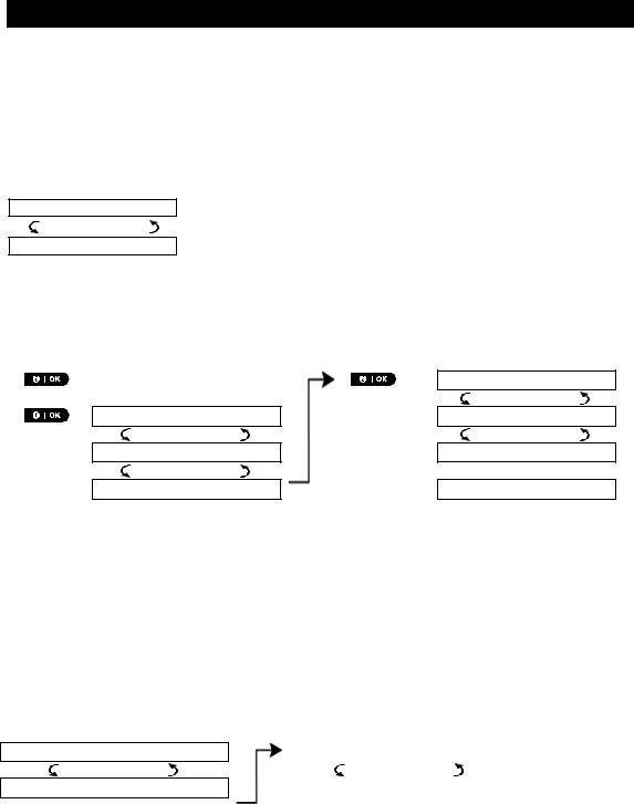
A.1 Entering the user settings menu & selecting an option
The following procedure describes how to enter and move within the User Settings menu. Detailed descriptions of the User Settings options are provided at the end of the procedure. To exit the User Settings menu – see section A.2.
1. You can enter the "USER SETTINGS" menu only when the system is disarmed.
2.Carefully read the section titled "Additional Information" according to the indicated references 1 etc. – see table at end of this section.
A.To enter the USER SETTINGS Menu
1.READY 00:00
2.USER SETTINGS
ENTER CODE:
Make sure the system is disarmed and then press the |
button |
repeatedly until the display reads [USER SETTINGS]. 1 |
|
Press |
|
The screen will now prompt you to enter your user code or present your proximity tag.
|
3. |
|
|
CODE |
|
Enter your User Code. 2 |
|
|||
|
|
|
|
|
||||||
|
|
|
|
|
||||||
|
|
|
|
SET BYPASS |
|
|
The display reads the first Setting option of the User Settings menu |
|||
|
|
|
|
|
|
|
[SET BYPASS]. 3 |
|
|
|
|
|
|
|
|
|
|
|
|||
|
|
|
|
|
|
|
|
|
|
|
|
B. To select an option |
|
|
|
|
|
||||
|
|
|
|
|
|
|
|
|
|
|
|
4. |
|
|
SET BYPASS |
|
|
Click the |
or |
button until the display reads the desired |
|
|
|
|
|
or |
|
setting option, for example, "TIME & FORMAT". |
||||
|
|
|
|
|
||||||
|
|
|
|
|
||||||
|
|
|
|
|
|
|
|
|||
|
5. |
|
|
TIME & FORMAT |
|
|
When the desired setting option appears on the display, press the |
|||
|
|
|
|
|
|
|
button to enter the setting process. |
|||
|
|
|
|
|
|
|||||
|
|
|
|
|
|
|
||||
|
|
|
Continue to the selected |
|
|
|
|
|
|
|
|
|
|
|
|
The remainder of the procedures for the selected setting options is provided |
|||||
|
|
|
setting option in B.1 - B.15 |
|
|
in sections B.1 to B.15. |
|
|||
|
|
|
|
|
|
|
|
|
|
|
|
|
|
|
|
|
|
|
|||
|
|
|
|
|
|
|
Additional Information (section B.1) |
|||
|
|
|
|
|
|
|
|
|
|
|
|
1 |
|
Display shown in disarm state when all zones are secured (00:00 or other digits show present time). |
|||||||
2a. If you have not already changed your personal code number, use the default setting – 1111.
b.Master User has access to all User Settings options. Other users have access only to the Bypass options.
c.If you enter an invalid user code 5 times, the keypad will be automatically disabled for a pre-defined period of time and the message WRONG PASSWORD will be displayed.
3The bypass options will be displayed in the User Settings menu only if enabled by the installer. Otherwise, the first User Settings option displayed will be [USER CODES].
D-307503 PowerMaster 360 User's Guide |
17 |

MENUS AND FUNCTIONS
C. User settings options menu
Click  until the display reads the desired setting option and then press
SET ZONE BYPASS
REVIEW BYPASS
RECALL BYPASS
USER CODES
DURESS CODE
PROXIMITY TAGS
KEYFOBS
TIME & FORMAT
DATE & FORMAT
AUTO-ARM ENABLE
AUTO-ARM TIME
PRIVATE REPORT
SQUAWK
SCHEDULER
VOLUME CONTROL
SERIAL NUMBER
PLNK curr.params
<OK> TO EXIT
Returns to first option
Use to bypass a faulty (exclude) or unsecured ("disturbed") zones, or to clear a bypassed zone. For further details and programming procedure see section B.1. 3
Use to quickly review the bypass scheme that is to see which zones are bypassed. For further details and reviewing procedure see section B.2. 3
Use to recall the last used bypassed scheme for reuse in next arming period. For further details and recalling procedure see section B.3. 3
Use to program the master user secret access code and the remaining seven other user codes. For further details and programming procedure see section B.4.
Use to program the duress code. For further details and programming procedure see section B.5.
Use to add new Proximity Tags to or to delete Proximity Tags when lost. For further details and programming procedure see section B.6.
Use to add new keyfob transmitters or to delete a keyfob transmitter if for example the keyfob is lost. For further details and programming procedure see section B.7.
Use to set the time clock to show the correct time and time format. For further details and programming procedure see section B.8.
Use to set the calendar date to show the correct date and date format. For further details and programming procedure see section B.9.
Use to enable or disable the option daily arming at predefined times (see Auto-Arm Time setting). For further details and programming procedure see section B.10.
Use to set the predetermined time for the automatic daily arming if enabled (see Auto-Arm Enable setting). For further details and programming procedure see
section B.11.
Use to program the four private telephone numbers for reporting alarm and other event messages to private subscribers. For further details and programming procedure see section B.12.
Use to enable or disable the squawk sound that is arm / disarm feedback indication. For further details and programming procedure see section B.13.
Use to set the daily / weekly time schedule for start and stop activation of devices connected to the PGM outputs. For further details and programming procedure see section B.14.
Use to adjust the volume level of the various system beeps, and chime signal. For further details and programming procedure see section B.15.
Use to read the system serial number and similar data see section B.16.
Use to read the current IP address of the PowerLink and similar data see section
B.17.
Use to exit from the “USER SETTINGS” menu back to Main Menu. For further details see section A.2.
18 |
D-307503 PowerMaster 360 User's Guide |
MENUS AND FUNCTIONS
A.2 Returning to the previous step or exiting the USER SETTINGS menu
During the setting process it is frequently necessary to return to the previous setting step or option (i.e. "to go
one level up") or to exit the User Settings menu.
A. To move one level up
To move one level up during the setting process, click  once. Each click takes you one level up or to the previous setting step:
|
B. To exit the USER SETTINGS menu |
|
|
|
|
|
|
|
|
|
Any screen |
To exit [USER SETTINGS], move up the menu by pressing |
repeatedly |
|
|
|
until the display reads [<OK> TO EXIT], or preferably, press |
once which |
|
|
|
or |
brings you immediately to the exit screen [<OK> TO EXIT]. |
|
|
|
|
|
|
|
|
|
||
|
|
|
||
|
<OK> TO EXIT |
When the display reads [<OK> TO EXIT], press |
||
|
|
|
|
|
|
|
|
|
|
|
READY 12:00 |
The system exits the [USER SETTINGS] menu and returns to the normal disarm |
|
|
|
|
|
state while showing the READY display. |
|
|
|
|
|
|
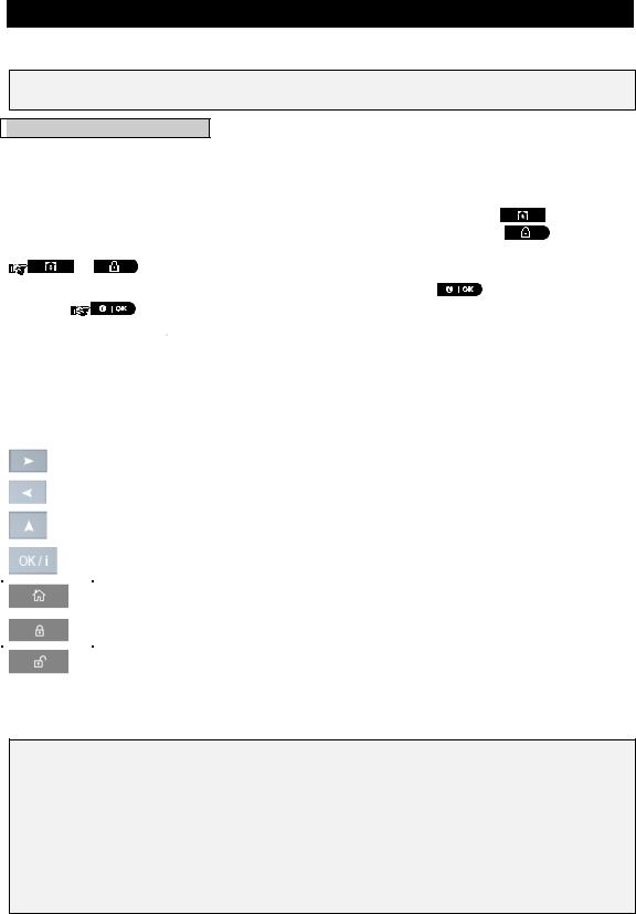
A.3 Keys used for navigation and settings
You can use the keypad for various programming functions. The following table provides a description of the keys and their functions.
Button |
Definition |
|
Navigation / Setting Function |
|
NEXT |
|
Use to move / scroll forward to the next menu options. |
|
|
|
|
|
BACK |
|
Use to move / scroll backward to the previous menu options. |
|
|
|
|
|
UP |
|
Use to move one level up in the menu or to return to previous setting step. |
|
|
|
|
|
OK |
|
Use to select a menu option or to confirm a setting or action. |
|
|
|
|
|
HOME |
|
Use to move one level up in the menu or to return to previous setting |
|
|
|
step. |
|
AWAY |
|
Use to jump back to the [<OK> TO EXIT] screen to quit programming. |
|
|
|
|
|
OFF |
|
Use to cancel, delete, clear or erase setting, data, etc. |
|
|
|
|
0 - 9 |
|
|
Numerical keypad used to enter numerical data. |
|
|
|
|
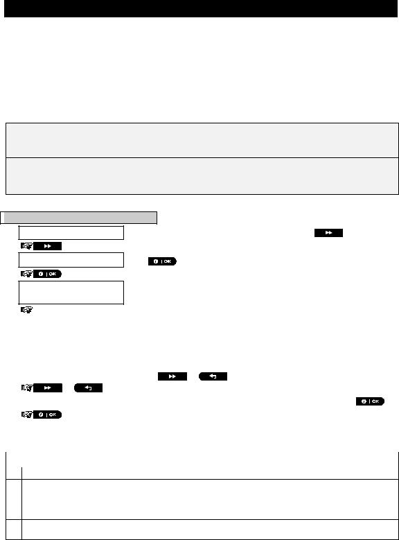
B.1 Setting the zone bypass option
Bypassing permits arming only part of the system while allowing free movement of people within certain zones when the system is armed. It is also used to temporarily remove from service faulty zones that require repair work or to deactivate a sensor if, for example, you are decorating a room.
Here you can set the Zone Bypass Scheme i.e. to scroll through the list of registered (enrolled) sensors to your PowerMaster-360 system and to Bypass (deactivate) faulty or disturbed sensors (either READY or NOT-READY) or to Clear (reactivate) BYPASSED zones (sensors).
Once you have set a Bypass Scheme you can use the following 3 options:
>To quickly review the bypassed zones – refer to section B.2.
>To quickly clear a bypassed zone i.e. to reactivate the bypassed zone – refer to section B.1.
>To repeat (recall) the last used zone bypassing scheme – refer to section B.3.
D-307503 PowerMaster 360 User's Guide |
19 |

MENUS AND FUNCTIONS
1. Zones will be bypassed throughout one disarm-arm period only. Disarming the system after arming will suspend the entire bypassing scheme but you can recall and reuse it as described in section B.3.
2.Fire zones cannot be bypassed.
3.Carefully read the section titled "Additional Information" according to the indicated references 1 etc. – see table at end of section B.3.
REMEMBER – ZONE BYPASSING COMPROMISES SECURITY!
A.To bypass a zone
1.SET ZONE BYPASS Enter the [USER SETTINGS] menu1, select the [SET ZONE BYPASS]2
|
|
|
|
option and press |
|
|
|
|
|
|
|
|
|
|
|
|
|
The first zone, Z01, is displayed. 3 |
||
|
|
Z01: READY |
|
|||
|
|
|
|
4 |
|
|
|
|
Z01: P1 P2 |
P3 |
|
|
|
|
|
|
|
|
||
|
|
|
|
|
|
|
|
|
Living Room |
|
|
|
|
2. |
|
|
|
|
|
|
|
or |
|
Click the |
or |
button until the display reads the zone you wish |
|
|
|
|||||
|
|
|||||
|
|
|
|
to bypass (or clear bypass), for example, "Z04" for Zone 04. After several |
||
|
|
Z04: NOT READY |
||||
|
|
seconds the LED on the respective device starts flashing indicating "it's me". |
||||
|
|
|
|
|||
|
|
|
|
4 |
|
|
|
|
Z04: P1 P2 |
P3 |
|
|
|
|
|
|
|
|
||
3. |
|
|
|
When the display reads the zone you wish to bypass press |
||
|
Kitchen |
|
||||
|
|
|
|
|
|
|
4.<OK> TO BYPASS The display now reads [<OK> TO BYPASS]. 5
To bypass the selected zone press 
5.Z04: BYPASSED A "Success Tune" ☺ sounds and the updated zone status is now displayed
i.e. [Z04: BYPASSED]. 8
B.To Clear a Bypassed Zone
6.Z04: BYPASSED Repeat steps 1 to 2 above.
|
|
Z04: P1 P2 |
P3 |
4 |
|
|
|
|
|
||
7. |
|
|
|
When the zone you wish to clear bypass appears on the display (for |
|
|
Kitchen |
|
|||
|
|
|
|
example, "Z04"), press |
to confirm. You can also identify the device |
|
|
|
|
||
|
|
|
|
by looking for the "it's me" LED indication on the displayed device. |
|
|
|
|
|
||
<OFF> TO CLEAR 8. 


Z04: READY
The display now reads [<OFF> TO CLEAR]. 5
To clear the bypassed zone, press the  button.
A "Success Tune" ☺ sounds and the updated zone status is now displayed, i.e. [Z04: READY] or [Z04: NOT READY]. 9
20 |
D-307503 PowerMaster 360 User's Guide |
 Loading...