

Page 1

PGM
Outputs
Switch Setting
Output Normal State
ON N.C -
Normally Close
OFF N.O –
Normally Open
ON N.C. = D
isarm N.O. = Arm
OFF N.C. = Arm
N.O. = Disarm
PGM----5555
PGMPGM
PowerMax Pro / PowerMaxComplete / PowerMaxExpress /
PowerMaster-10 G2 / PowerMaster-30 G2 /
PowerMaster-33 G2 Interface Unit
1. DESCRIPTION
1. DESCRIPTION
1. DESCRIPTION1. DESCRIPTION
PGM-5 (see Figure 1) is an output interface module designed to
provide alarm, trouble events and status signals to external devices
such as long range wireless monitoring transmitters, CCTV systems,
home-automation systems, LED annunciation panels, etc.
The PGM-5 provides 5 solid state relay contact outputs and is designed
to be used as a plug-in internal add-on module with PowerMax Pro,
PowerMaxComplete, PowerMaxExpress, PowerMaster-10 G2,
PowerMaster-30 G2 and PowerMaster-33 G2 control panels.
Note: The PGM-5 will be active only if the PGM-5 option was enabled
in the factory default of the control panel. For PowerMaster control
panels v18 and above, it is required to enable or disable the PGM-5
via the Installer Mode. For detailed instructions, refer to the
PowerMaster Installer Guide.
Table 3 – N.O or N.C Outputs Normal State Setting
OUT
1,2, 3 & 5
OUT 4 SW-2
Each output will change its state upon occurrence of an event or change
of status and will revert to its normal state upon restoral of the event or
change of status.
SW-1
PowerMax Pro
Figure 2 – Typical Application
Figure 3 displays electrical wiring diagrams where the PGM-5 module
is connected to an alarm transmitter and to a LED Annunciation
Panel.
PGM-5
PGM-5
Installation
Instructions
Alarm types:
1. Alarm
2. Panic
3. Fire
4. Arm/disarm
5. Low bat./Gas Co/
AC fail./Gen. trbl
ALARM TRANSMITTER
Outputs 1 to 4 provide pre-set signals while output 5 is programmable
using DIP switches SW-3 & SW-4 – see Tables 1 & 2.
Table 1 – Output Definitions
Output Event Type
OUT 1 Burglar & 24Hr audible alarm (Bell time duration).
OUT 2 Panic (2 sec. pulse)
OUT 3 Fire (Bell time duration).
OUT 4 Arm / Disarm (actual status of the panel)
OUT 5 See table 2
Table 2 – OUT 5 Signal Setting
SW-4 SW-3 Event Type
OFF OFF General trouble (until restored)
ON OFF General Low battery (until restored)
OFF ON Gas or CO alarm (until restored)
ON ON AC failure reported (until restored)
The outputs can be set to either normally open (N.O) or normally
closed (N.C), according to the specific application, using DIP switches
SW-1 (for outputs 1, 2, 3 & 5) and SW-2 for output 4 (Arm/Disarm) –
see table 3.
D-302182 PGM-5 Installation Instructions 1
Figure 1 – PGM-5 Printed Circuit
Tamper & 24 Hr silent (2 sec. pulse)
OUT 1
OUT 2
OUT 3
OUT 4
OUT 5
COM
PGM-5
OUT 1
OUT 2
OUT 3
OUT 4
OUT 5
COM
Figure 3 – Electrical Wiring of PGM-5 Module and Alarm
Transmitter/ LED Annunciation Panel
INPUT 1
INPUT 2
INPUT 3
INPUT 4
INPUT 5
( )
or
COM
LED ANNUNCIATION
PANEL
LED
1 k
Ω
Alarm
1 k
Ω
Panic
1 k
Ω
Fire
1 k
Ω
Arm /Disarm
1 k
Ω
Programmable
12V
0 V
Page 2
2. SPECIFICATIONS
2. SPECIFICATIONS
2. SPECIFICATIONS2. SPECIFICATIONS
Number of Outputs: 5
Output Type: Solid State Relay – dry contact.
Predefined Output State: N.O. or N.C. programmable (by DIP switch).
Maximum Load Current: 100 mA
Maximum Peak Current: 350 mA @10 ms
3.
3. MOUNTING AND WIRING
MOUNTING AND WIRING
3. 3.
MOUNTING AND WIRINGMOUNTING AND WIRING
In the PowerMax Pro, PowerMaxComplete, PowerMaster-30 G2 and PowerMaster-33 G2 control panels, press the PGM-5 module into the
marked location (see Figures 4a, 4b and 4e) until a click is heard.
In the PowerMaxExpress and PowerMaster-10 G2 control panels, use the two screws to fasten the PGM-5 module into the marked location, as
illustrated in Figure 4c and 4d.
Output Resistance RON: 16Ω max. @IL = 100 mA
N.O. Leakage Current: <1 uA
Maximum Load Voltage: 15 V
Operating Temperatures: 0°C to 50°C (32°F to 122°F)
Compliance with Standards: EN 50130-4
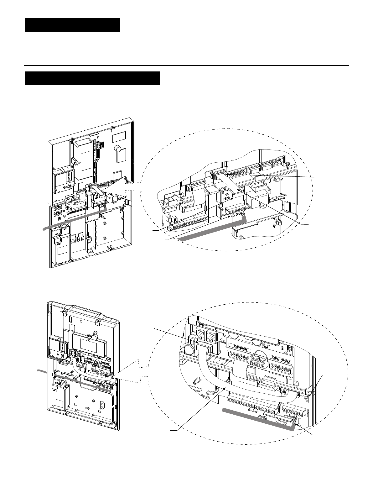
POWERMAX PRO
Connect one side of the flat cable
into the PGM-5 connector and the
other side into the PowerMax Pro
Front unit
PC connector
PowerMax Pro
PC Connector
Flat cable
PGM-5
Back unit
Figure 4a – PGM-5 Mounting and Wiring in PowerMax Pro Control Panel
* It is strongly recommended to route the cable as shown to prevent interference which may occur if routed too close to the control panel's antennas.
Wiring*
POWERMAXCOMPLETE
Connect one side of the flat cable into the
PGM-5 connector and the other side into the
PowerMaxComplete BBA connector
PGM-5
Front unit
Back unit
PowerMaxComplete
BBA Connector
Flat cable
Figure 4b – PGM-5 Mounting and Wiring in PowerMaxComplete Control Panel
* It is strongly recommended to route the cable as shown to prevent interference which may occur if routed too close to the control panel's antennas.
Wiring*
2 D-302182 PGM-5 Installation Instructions
Page 3

Front unit
Back unit
Connect one side of the flat cable into the
PGM-5 connector and the other side into the
PowerMaxExpress BBA connector
Screws for
fastening
PGM-5
module
POWERMAXEXPRESS
PGM-5
Flat cable
PowerMaxExpress
BBA Connector
Wiring*
Figure 4c – PGM-5 Mounting and Wiring in PowerMaxExpress Control Panel
* It is strongly recommended to route the cable as shown to prevent interference which may occur if routed too close to the control panel's antennas.
Figure 4d – PGM-5 Mounting and Wiring in PowerMaster-10 G2 Control Panel
* It is strongly recommended to route the cable as shown to prevent interference which may occur if routed too close to the control panel's antennas.
D-302182 PGM-5 Installation Instructions 3
Page 4

Figure 4e – PGM-5 Mounting and Wiring in PowerMaster-30 G2 Control Panel
W.E.E.E. Product Recycling Declaration
VISONIC LTD. 2014 PGM
-
5 D-302182 (Rev
3, 9/14
)
* It is strongly recommended to route the cable as shown to prevent interference which may occur if routed too close to the control panel's antennas.
* It is strongly recommended to route the cable as shown to prevent interference which may occur if routed too close to the control panel's antennas.
WARRANTY
WARRANTY
WARRANTYWARRANTY
Visonic Limited (the “Manufacturer") warrants this product only (the "Product") to the original purchaser only
(the “Purchaser”) against defective workmanship and materials under normal use of the Product for a
period of twelve (12) months from the date of shipment by the Manufacturer.
This Warranty is absolutely conditional upon the Product having been properly installed, maintained and
operated under conditions of normal use in accordance with the Manufacturers recommended installation
and operation instructions. Products which have become defective for any other r eason, according to the
Manufacturers discretion, such as improper installation, failure to follow recommended installation and
operational instructions, neglect, willful damage, misuse or v andalism, accidental damage, alteration or
tampering, or repair by anyone other than the manufacturer, are not covered by this Warranty.
The Manufacturer does not represent that this Product may not be compromised and/or circumvented or
that the Product will prevent any death and/or personal injury and/or damage to property resulting from
burglary, robbery, fire or otherwise, or that the Product will in all cases provide adequate warning or
protection. The Product, properly installed and maintained, only reduces the risk of such events without
warning and it is not a guarantee or insurance that such events will not occur.
THIS WARRANTY IS EXCLUSIVE AND EXPRESSLY IN LIEU OF ALL OTHER WARRANTIES,
OBLIGATIONS OR LIABILITIES, WHETHER WRITTEN, ORAL, EXPRESS OR IMPLIED, INCLUDING
ANY WARRANTY OF MERCHANTABILITY OR FITNESS FOR A PARTICULAR PURPOSE, OR
OTHERWISE. IN NO CASE SHALL THE MANUFACTURER BE LIABLE TO ANYONE FOR ANY
CONSEQUENTIAL OR INCIDENTAL DAMAGES FOR BREACH OF THIS WARRANTY OR ANY OTHER
WARRANTIES WHATSOEVER, AS AFORESAID.
THE MANUFACTURER SHALL IN NO EVENT BE LIABLE FOR ANY SPECIAL, INDIRECT,
INCIDENTAL, CONSEQUENTIAL OR PUNITIVE DAMAGES OR FOR LOSS, DAMAGE, OR EXPENSE,
INCLUDING LOSS OF USE, PROFITS, REVENUE, O R GOODWILL, DIRECTLY OR INDIRECTLY
ARISING FROM PURCHASER’S USE OR INABILITY TO USE THE PRODUCT , OR FOR LOSS OR
DESTRUCTION OF OTHER PROPERTY OR FROM ANY OTHER CAUSE, EVEN IF MANUFACTURER
HAS BEEN ADVISED OF THE POSSIBILITY OF SUCH DAMAGE.
THE MANUFACTURER SHALL HAVE NO LIABILITY FOR ANY DEATH, PERSONAL AND/OR BODILY
INJURY AND/OR DAMAGE TO PROPERTY OR OTHER LOSS WHETHER DIRECT, INDIRECT, INCIDENTAL,
CONSEQUENTIAL OR OTHERWISE, BASED ON A CLAIM THAT THE PRODUCT FAILED TO FUNCTION.
For information regarding the recycling of this product you must contact the company from which you orignially purchased it. If you are discarding this product and not
returning it for repair then you must ensure that it is returned as identified by your supplier. This product is not to be thrown away with everyday waste.
EMAIL: info@visonic.com
INTERNET: www.visonic.com
Directive 2002/96/EC Waste Electrical and Electronic Equipment.
4 D-302182 PGM-5 Installation Instructions
Figure 4f – PGM-5 Mounting and Wiring in PowerMaster-33 G2 Control Panel
However, if the Manufacturer is held liable, whether directly or indirectly, for any loss or dam age arising
under this limited warranty, THE MANUFACTURER'S M AXIMUM LIABILITY (IF ANY) SHALL NOT IN
ANY CASE EXCEED THE PURCHASE PRICE OF THE PRODUCT , which shall be fixed as liquidated
damages and not as a penalty, and shall be the complete and exclusive remedy against the Manufacturer.
When accepting the delivery of the Product, the Purchaser agrees to the said conditions of sale and
warranty and he recognizes having been informed of.
Some jurisdictions do not allow the exclusion or limitation of incidental or consequential damages, so these
limitations may not apply under certain circumstances.
The Manufacturer shall be under no liability whatsoever arising out of the corruption and/or m alfunctioning
of any telecommunication or electronic equipment or any programs.
The Manufacturers obligations under this Warranty are limited solely to repair and/or replace at the
Manufacturer’s discretion any Product or par t thereof that may prove defective. Any repair and/or
replacement shall not extend the original Warranty period. The Manufacturer shall not be responsible for
dismantling and/or reinstallation costs. To exercise this Warranty the Product must be returned to the
Manufacturer freight pre-paid and insured. All freight and insurance costs are the responsibility of the
Purchaser and are not included in this Warranty.
This warranty shall not be modified, varied or extended, and the Manufacturer does not authorize any person to
act on its behalf in the modification, variation or extension of this warranty. This warranty shall apply to the Product
only. All products, accessories or attachments of others used in conjunction with the Product, including batteries,
shall be covered solely by their own warranty, if any. The Manufacturer shall not be liable for any damage or loss
whatsoever, whether directly, indirectly, incidentally, consequentially or otherwise, caused by the malfunction of
the Product due to products, accessories, or attachments of others, including batteries, used in conjunction with
the Products. This Warranty is exclusive to the original Purchaser and is not assignable.
This Warr anty is in addition to and does not aff ect your legal rights. Any provision in this warranty which is
contrary to the Law in the state or country were the Product is supplied shall not apply.
Warning: The user must follow the Manufacturer’s installation and operational instructions including testing
the Product and its whole system at least once a week and to take all necessary precautions for his/her
safety and the protection of his/her property.
1/08
 Loading...