

Page 1

NEXT PG2
NEXT PG2 /
NEXT PG2NEXT PG2
/
/ /
Installation Instructions
NEXT
NEXT K9
NEXTNEXT
PowerG, Wireless, PIR /Pet Tolerant Motion Detector
1. INTRODUCTION
1. INTRODUCTION
1. INTRODUCTION1. INTRODUCTION
The Next PG2 and Next K9-85 PG2 are 2-way, microprocessor-controlled, wireless digital PIR detectors.
The detectors features are as follows:
• For use with all PowerMaster® control panels (version 10 and higher).
• Combined Fresnel and cylindrical optics, up to 15 meters (49 ft).
• The Next PG2 includes wall creep zone protection.
• In Next PG2 and Next K9-85 PG2, Target Specific Imaging™ (TSI) technology is used for distinction
between human beings and pets weighing up to 38 kg (85lb).
• Includes a fully supervised PowerG transceiver.
• The advanced True Motion Recognition™ algorithm (patented) allows distinguishing between the true
motion of an intruder and any other disturbances which may cause false alarms.
• Sophisticated frequency domain digital signal processing.
• Built-in link quality indicators; no need for the installer to physically approach the control panel thus making
installation faster and easier.
• No vertical adjustment is needed.
• Motion event counter determines whether 1 or 2 consecutive motion events will trigger an alarm.
• Automatic termination of walk-test after 15 minutes.
• Microprocessor-controlled temperature compensation.
• Sealed chamber protects the optical system.
• Front cover and back tamper switches, for improved tamper protection.
• White light protection.
• Notes: 1. The pet immunity feature was not evaluated by UL.
2. For CE installations, the pet immunity was not evaluated by DNV.
3. The pet immunity feature is not evaluated and certified by Applica Test & Certification AS.
K9----85
K9K9
85 PG2
8585
PG2
PG2PG2
A
B
A. LED
B. Lens
Figure 1: External View
2222.
. INSTALLATION
INSTALLATION
. .
INSTALLATIONINSTALLATION
2.1 General Guidance (see Fig. 2)
1. Keep away from heat sources.
2. Do not expose to air drafts.
3. Do not install outdoors.
4. Avoid direct sunshine.
5. Keep wiring away from power cables.
6. Do not install behind partitions.
7. Mount on solid stable surface.
8. Installed in accordance with NEC, NFPA 70.
9. Installed in accordance with UL 681, Standard for
Installations and Classifications of burglar and Holdup
Alarm Systems.
Important! The Next K9-85 PG2 detector is tolerant to 38 kg (85 lb) animals moving on the floor or climbing on
furniture as long as the activity takes place below 1 m (3 ft). Above the 1 m (3 ft) height limit, the detector is tolerant
to 19 kg (42 lb) pets, but the pet immunity will decrease as the pet gets closer to the detector. It is therefore
recommended to select a mounting location that minimizes potential close proximity of animals.
WARNING! To comply with FCC and IC RF exposure compliance requirements, the PIR detector should be located at a distance of at least 20
cm from all persons during normal operation. The antennas used for this product must not be co-located or operated in conjunction with any other
antenna or transmitter
1 2 3
4 5 6
7
Figure 2. General Guidelines
D-302413 NEXT PG2, NEXT K9-85 PG2 Installation Instructions 1
Page 2

Configure
See Note
2.2 Mounting (see Fig. 3)
Notes:
1. Mount the detector so that its orientation is perpendicular to the expected intrusion path.
2. For installations of detector at 2m high, Dead zone is 2ft at 0m high and 0.5ft at 1.5m high.
2
4
3
A
B
1
1. Release screw and remove cover.
2. Push catch and remove board.
3. Insert battery.
4. Mounting
Caution!
Risk of explosion if battery is replaced by an incorrect type. Dispose of used battery according to manufacturer's instructions.
Note: Back Tamper must be enabled for UL installations.Figure 3. Mounting
A. Front Tamper switch
B. Back Tamper switch.
C. On surface
D. In corner
C D
2.3. Enrollment
Refer to the PowerMaster panel's Installer Guide and follow the procedure under the "02:ZONES/
A general description of the procedure is provided in the following flow chart.
Step 1 Step 2 Step 3 Step 4 Step 5 Step 6
Enter the Installer menu
and select
“02:ZONES/DEVICES”
02.ZONES/DEVICES
means scroll and select
Notes:
[1] If the detector is already enrolled you can configure the detector parameters via the “Modify Devices” option – see Step 2.
[2] Select the "Device Settings" option and refer to section 2.4 to configure the detector parameters.
Select "ADD NEW
DEVICE" Option
See Note [1]
ADD NEW DEVICES
MODIFY DEVICES
Enroll the device or Enter
the device ID
ENROLL NOW or
ENTR ID:XXX-XXXX
02:ZONES/ DEVICES
02:ZONES/02:ZONES/
Select the desired Zone
Number
Z14:Motion Sens
ID No. 120-XXXX
DEVICES" option of the Installer Menu.
DEVICESDEVICES
Configure Location,
Zone Type &
Chime Parameters
Z14.LOCATION
Z14.ZONE TYPE
Z14.SET CHIME
Z14.DEV SETTINGS
the
Detector
[2]
2.4. Configuring the Detector Parameters
Enter the menu and follow the configuration instructions for the Next PG2 / Next K9-85 PG2 PIR detector as described in
the following table.
Alarm LED
Event Counter
DISARM Activity
2 D-302413 NEXT PG2, NEXT K9-85 PG2 Installation Instructions
DEVICE SETTINGS
Option Configuration Instructions
Here you determine whether or not the alarm LED indication will be activated.
•
•
•
•
•
•
Optional settings: LED ON (default) and LED OFF.
Here you determine whether an alarm will be activated upon continued motion (low sensitivity) or upon a single
alarm event (high sensitivity)..
Optional settings: LOW sensitive (default) and HIGH sensitive.
Here you determine whether or not to set the activity time during disarm.
Optional settings: NOT Active (default), YES – no delay, YES + 5s delay, YES + 15s delay, YES + 30s delay,
YES + 1m delay, YES + 2m delay, YES + 5m delay, YES + 10m delay, YES + 20m delay and YES + 60m
delay.
Page 3

3333.
Compliance with Standards
According to EN 50131
. LOCAL DIAGNOSTICS TEST
LOCAL DIAGNOSTICS TEST
. .
LOCAL DIAGNOSTICS TESTLOCAL DIAGNOSTICS TEST
NOTE: Run a diagnostic test at least once a year to ensure that the detector is working correctly.
A. Separate the base from the cover (see Fig. 3).
B. Put back the cover to return the tamper switch to its normal (undisturbed) position, and then secure the front cover to the base with the
case closure screw.
C. The Next PG2 / Next K9-85 PG2 will enter a 2 min. stability period. During this time the red LED blinks.
D. Walk-test the coverage area - see Fig. 5. Walk across the far end of coverage pattern in both directions, The red LED lights each time
your motion is detected followed by 3 LED blinks.
The following table indicates received signal strength indication.
LED response Reception
Green LED blinks Strong
Orange LED blinks Good
Red LED blinks Poor
IMPORTANT! Reliable reception must be assured.
Therefore, "poor" signal strength is not acceptable. If you
receive a "poor" signal from the detector, re-locate it and
re-test until a "good" or "strong" signal strength is
received (in regions requiring UL-compliant installation,
only “strong” signal strength is permitted).
Notes:
1. For detailed Diagnostics Test instructions refer to the
control panel Installer Guide.
2. For UL/CUL installations, the test result must be
“Strong”.
No blinks No communication
A. ENROLL button
EVENT
1
2
LED
A
Figure 4. Device enroll button
Rx Tx
4. SPECIAL COMMENTS
Even the most sophisticated detectors can sometimes be defeated or may fail to warn due to: DC power failure / improper connection,
malicious masking of the lens, tampering with the optical system, decreased sensitivity in ambient temperatures close to that of the human
body and unexpected failure of a component part.
The above list includes the most common reasons for failure to detect intrusion, but is by no means comprehensive. It is therefore
recommended that the detector and the entire alarm system be checked weekly, to ensure proper performance.
An alarm system should not be regarded as a substitute for insurance. Home and property owners or renters should be prudent enough
to continue insuring their lives and property, even though they are protected by an alarm system.
5. COMPLIANCE WITH STANDARDS
5. COMPLIANCE WITH STANDARDS
5. COMPLIANCE WITH STANDARDS5. COMPLIANCE WITH STANDARDS
Europe: EN 300220, EN 50131-1 Grade 2, Class II. EN 301489, EN 50130-4, EN 60950, EN 50131-2-2,
Also complies to USA: CFR47 Part 15; Canada: RSS 210;
UK: This product is suitable for use in systems installed to conform to PD6662:2010 at Grade 2 and environmental class 2. DD243 and BS8243.
The Power G peripheral devices have two- way communication functionality, providing additional benefits as described in the technical brochure. This functionality
has not been tested to comply with the respective technical requirements and should therefore be considered outside the scope of the product’s certification.
EN 50131-1 Security Grade
EN 50131-1 Environmental Class
Visonic Ltd.
M/N: RFD
FCC ID: WP3RFD
IC: 1467-RFD
This device has been tested and found to comply with the limits for a Class B digital device, pursuant to Part 15 of the FCC Rules. These
limits are designed to provide reasonable protection against harmful interference in residential installations. This equipment generates uses
and can radiate radio frequency energy and, if not installed and used in accordance with the instructions, may cause harmful interference to
radio and television reception.
However, there is no guarantee that interference will not occur in a particular installation. If this device does cause such interference, which can
be verified by turning the device off and on, the user is encouraged to eliminate the interference by one or more of the following measures:
– Re-orient or re-locate the receiving antenna.
– Increase the distance between the device and the receiver.
– Connect the device to an outlet on a circuit different from the one that supplies power to the receiver.
– Consult the dealer or an experienced radio/TV technician.
D-302413 NEXT PG2, NEXT K9-85 PG2 Installation Instructions 3
EN 50131-6 Environmental IP55.
The NEXT PG2 and NEXT K9-85 PG2 are compatible with the RTTE requirements - Directive 1999/5/EC
of the European Parliament and of the Council of 9 March 1999 and EN50131-1 Grade 2 Class II.
Certified by Norwegian accredited certification body Applica Test & Certification AS in accordance with
EN 50131-2-2, EN 50131-6, EN 50131-5-3, EN 50130-4, and EN 50130-5.
Applica T&C has certified only the 868 MHz variant of this product.
-1:2006 and A1:2009, this equipment can be applied in installed systems
up to and including Security Grade 2.
Class II
Page 4
W.E.E.E. Product Recycling Declaration
VISONIC LTD.
2015
D-
302413
NEXT PG2, NEXT
K9-85
PG2
(REV. 7, 6
/15) Please see separate Warranty statement
WARNING! Changes or modifications to this unit not expressly approved by the party responsible for compliance could void the user’s
authority to operate the equipment.
This device complies with FCC Rules Part 15 and with Industry Canada licence-exempt RSS standard(s). Operation is subject to two
conditions: (1) This device may not cause harmful interference, and (2) this device must accept any interference that may be received
or that may cause undesired operation.
Le present appareil est conforme aux CNR d'Industrie Canada applicables aux appareils radio exempts de licence. L'exploitation est
autorisee aux deux conditions suivantes :(1) l'appareil ne doit pas produire de brouillage, et (2) l'utilisateur de l'appareil doit accepter
tout brouillage radioelectrique subi, meme si le brouillage est susceptible d'en compromettre le fonctionnement.
For information regarding the recycling of this product you must contact the company from which you orignially purchased it. If you are discarding this product and not
returning it for repair then you must ensure that it is returned as identified by your supplier. This product is not to be thrown away with everyday waste.
APPENDIX:
APPENDIX: SPECIFICATIONS
APPENDIX:APPENDIX:
GENERAL
Detector Type Dual element low-noise pyroelectric sensor
Lens Data No. of Curtain Beams / curtains:
Max. Coverage 15 x 15 m, (49 x 49 ft) / 90°
Pet Immunity (Next K9-85 PG2
only)
ELECTRICAL
Power Supply Type C
Internal Battery 3V Lithium battery, type CR-123A or equivalent
Notes:
1. Use only the above battery type.
2. For UL installations use Gold Peak (GP) CR123A only.
Nominal Battery Capacity 1450 mA/h
Battery Life (for typical use) 6 to 8 years
Low Battery Threshold 2.5 V
FUNCTIONAL
True Motion Event Verification 2 remote selections at panel - LOW, HIGH
Alarm Period 2 seconds
WIRELESS
Frequency Band (MHz) Europe and rest of world: 433-434, 868-869 USA: 912-919
Communication Protocol PowerG
Supervision Signaling at 4-min. intervals
Tamper Alert Reported when a tamper event occurs and in any subsequent message, until the tamper switch is restored
MOUNTING
Height
Installation Options
ACCESSORIES
ENVIRONMENTAL
RFI Protection >20 V/m up to 2000 MHz, excluding inband frequencies
Operating Temperatures -10°C to 50°C (14°F to 122°F) indoor
Storage Temperatures -20°C to 60°C (-4°F to 140°F)
Humidity Average relative humidity of up to approximately 75% non-condensing. For 30 days per year the relative humidity may vary
PHYSICAL
Size (H x W x D) 94.5 x 63.5 x 53.0 mm (3-11/16 x 2-1/2 x 2-1/16”)
Weight (with battery) 70 g (2.5 oz).
Color White
PATENTS
Directive 2002/96/EC Waste Electrical and Electronic Equipment.
SPECIFICATIONS
SPECIFICATIONSSPECIFICATIONS
Next PG2: 18 far, 18 mid, 10 close.
Next K9-85 PG2: 18 far, 18 mid, 18 close
Note: Lens – Reflex II PIR, Fresnel type lens With Optical attenuation in the
lower part of the lens. Lens material is High Density Polyethylene (HDPE). Part
of Enclosure Cover (Item 1) and snapped to the Enclosure Base (Item 2) by two
tabs and one screw.
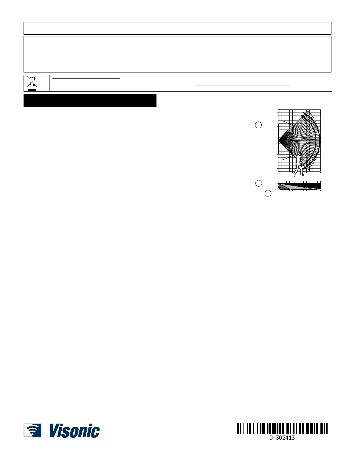
A. HORIZONTAL VIEW
B. VERTICAL VIEW
C. Next PG2: 0.5-4m, Next K9-85 PG2: 2-4m
Up to 38 kg (85 lb)
1.8 - 2.4 m (6 - 8 ft). For Next PG2, the recommended height is up to 2.1 m (7 ft)
Surface or corner
BR-1: Surface mounted swivel bracket, adjustable 30° down and 45° left/45° right.
BR-2: BR-1 with a corner adapter
BR-3: BR-1 with a ceiling adapter
Note: UL did not evaluate the product with the use of the BR brackets
Note: UL tested 0°C to 49°C
between 85 % and 95 % non-condensing
Note: For UL installations, relative humidity is 85%.
U.S. Patents 5,693,943 6,211,522 D445,709 (another patent pending)
10m
32.8ft
90°
5m
A
16.4ft
0
5m
16.4ft
10m
32.8ft
0
5
2.1 m
B
(6.9 ft)
C
16.4
0
5 10 15 m
16.4 32.8 49.2 ft
10
32.8
15 m
49.2 ft
Fig. 5. Coverage Pattern & Walk-test
EMAIL: info@visonic.com
INTERNET: www.visonic.com
4 D-302413 NEXT PG2, NEXT K9-85 PG2 Installation Instructions
 Loading...