

Page 1
055
Flush Mount PIR Detectors
,1752'8&7,21
The MR-4000 (vertical unit) and MR-4000R (horizontal unit) are
flush mounted PIRs for wired installations. They fit into virtually
any standard single-gang elec tri cal box, but may also be i nstal led
directly int o the wall without a box or a special inst allation kit.
Superior engineering gives you these added features:
• Flush mounting in a standard
electrical box
• Ideal for pre-wired installations
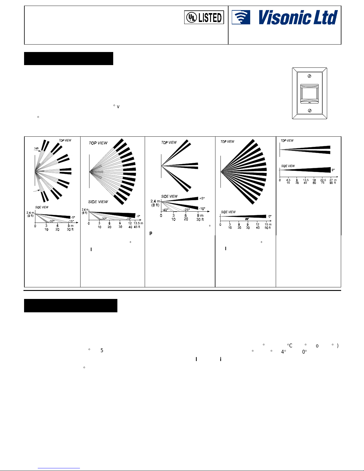
• 145 ultra-wide angle lens
• Super RFI protection
• Virtually zero fal se alarms
Maximum coverage:
10 m (30 ft) radius/145°
Application: provides the
largest and widest room
coverage for generalpurpose applications.
(Standard Lens)
Maximum coverage:
13.5 m (45 ft) radius/90
Application: general use -
high density coverage.
Figure 2
Lens No. 4, Ultra-Wide
Lens No. 1, Wide-Angl e
• Interchangeable lenses
• 12 vertical and hori zontal
adjustment
• Programmable pulse counter
• Plug-in wiring connector
• Entirely sealed construction
Max. coverage:
Application: 3 vertical "finger
curtains" which may be used as
3 individual traps within the
protected area. The coverage of
each curtain should be walktested-separately.
NOTE! A wide dead zone exists
between the curtains.
Figure 3
Lens No. 3, Triple Curtain
Figure 4
Installation Instructions
The MR-4000 provides a vari ety of
outstanding features including
adjustable pulse counter and RFl
protection up to 1000 MHz, to
ensure the highest level of reliability
and false alarm immunit y along wi th
added flexibility.
User-friendl y design includes installation aids for precise positioning at
the desired height.
9 m (30 ft) / 90
.
Maximum coverage:
15 m (50 ft) radius/90.
Application: allows pets to
move freely under coverage
pattern, undetected.
Mounting Height:
0.8 to 1.5 m (2.5 to 5 ft)
Figure 5
Lens No. 5, Pet Alley
Figure 1. Model MR-4000
for Vertical Installation
Maximum coverage:
27 x 3 m (90 x 10 ft)
Application: corridors and
long walls.
Mounting Height:
0.8 to 1.2 m (2.5 to 4 ft)
Beam Splitting: By dual-
element detector that creates
two detection zones for each
segment in the lens array,
doubling the number of detecting beams in the coverage
pattern
.
Figure 6
Lens No. 2, Long-Range
63(&,),&$7,216
OPTICAL
Standard Lens: Lens No. 4 is the standar d pattern s upplied wi th
each MR-4000. It provides 34 beams in 3 detec tion layers, 145 °
ultra-wide angle, maximum c overage area of 9 m (30 ft) radius.
Interchangeable Lenses (same as used with MR-3000 series):
Lens No. 1 - Wide-Angle 90, 13.5 m (45 ft) radius.
Lens No. 2 - Long-Range, 27 m x 3 m (90 ft x 10 ft )
Lens No. 3 - Triple curtain, 9 m (30 ft)
Lens No. 5 - Pet Alley, 90, 15 m (50 ft) radius.
Calibration: 0° to -12° (vertical); ±7.5° (horizontal)
ELECTRICAL
Voltage: 9 to 16 VDC.
Current Drain: 25 mA.
Relay Output: Normally Closed (fail safe) contacts. 18-ohm
resistor in series with contacts. Rat ing - 0.1 A resistive /30 VDC.
Alarm Period: 2-3 seconds.
Pulse Counter: Selectable 1 or 3 pulse operation.
Tamper Contacts (opti onal): N. C., 0.5 A resisti ve / 30 VDC.
LED: Switchable ON or OFF.
Detector: Dual-element low-noise pyroelectric sensor.
DE1141 1
MOUNTING
Flush mounted into virtually any standard single-gang electrical
box or installed directly into the wall (without box).
ENVIRONMENTAL
Operating Temperature: -10C to 50C (14F to 122F).
Storage Temperature: -20C to 60C (-4F to 140F).
RFl Protection: No alarm when tested on 21 different
frequencies fr om 20 to 1000 MHz with 124 W att radio trans mitter
at 3 m (10 ft) distance (equivalent to field strengt h of 20 V/m).
PHYSICAL
Dimensions: 125 x 85 x 48 mm (5 x 3.3 x 1.9 in.).
Weight: 90 g (3 oz).
Color: Soft white.
MODELS AVAILABLE
MR-4000: Standard model for vertical mounting.
MR-4000R: For horizontal mounting.
ACCESSORIES:
TS-1: Tamper switch module.
MRB-403: Standard single-gang back box.
Page 2

,167$//$7,21
&ORVLQJDQG2SHQLQJ WKH 'HWHFW RU
Position the fr ont cover (see Fig. 7) in the detect or housing, the
small latches al igned wi th t hei r c or res pondi ng lat c h holder s . Pus h
the front cover gentl y until a click is heard. The l ens assembly,
which is located behind the front cover, is adjustable vertically.
Locking screws are provided to secure the lens assembly after
vertical adjustment and to hold the detector in the electrical box.
Opening the detector:
Using a screwdr iver, release the cover by gently pushing on the
latches from t he rear of the det ector hous ing, until the fr ont c over
disengages.
Figure 7. MR-4000 Constr uction
&KDQJLQJ/HQVHV
Fig. 8 shows parts and construction of MR-4000 Lens Assembly.
Note: The Positioning Guides of model MR-4000R are slightly
different from model MR-4000 and are located on the sides of the
lens housing - see Fi gure 11. To change or adjust a lens, r elease
and remove the two lens-lock ing cl ips, l ocated on both s ides of the
lens, by pushing them from inside the cover (see Figure 9).
Install the new l ens with t he smooth sur face out side and the lens
number held at the upper lef t corner, opposite the l ens positioning
pointer - see figure 8. From inside the lens assembly, carefully
center the lens by sliding it to the right or left. The lens is
centered when both lens edges emerge equally above the frame
of the lens housing.
Holding firmly in place, insert the lens locking clips from the
outside (flanges pointed outwar d) and firmly pus h into place unti l
a click is heard - see Figures 8 and 10.
Before closing the detect or, the lens assembl y should be held in
the correct position relative to the detector. The positioning
guides and the pointer of the lens assembly assure correct
positioning of the lens ass embly r elati ve to the f ront c over. Fi gure
11 shows the lens hous ing positioning of bot h models: MR-4000
and MR-4000R.
Model MR-4000:
The pointer is placed
close to "A" (imprinted on the inner side
of the cover).
Model MR-4000R:
The pointer is pl aced
close to "B". The two
guiding studs assure
correct pos itioning of
the lens assembly in
each model and
allow movement of
the lens assembly for
vertical adjustment.
Figure 8. Lens Assembly ( M R-4000)
Figure 9. Removing Lens
Locking Clips
Figure 10. Locking the Lens
Figure 11. Positi oning the Lens Housing
6HOHFWLQJWKH 0RXQWLQJ/RFDWLRQ
A. The MR-4000 detector is much more sensitive to motion
crossing the beams of its coverage pattern than to motion
towards or away from the detector. Therefore, select the
mounting location s o that t he expected mot ion of an int r uder wi ll
cross the beams of the selected pattern.
NOTE: Passive infrared detectors are sensitive to changes in
infrared energy caused by an object moving across the unit's field of
view. The changes in infrared energy, detec ted by a PIR, depend
on the amount of infrared energy transmitted by t he moving object.
The changes also depend on the temperature difference bet ween
the object and the background. As a result, the PIR may fail to
respond under certain temperature and background conditions, in
which the temperature difference is too small. It is therefore
recommended that the PIR be aimed towards the coolest place in
the protected area, to obtain the maximum sensiti vi ty in ins tal lati ons
where high ambient temperatures are expected.
B. Select the most convenient mounting height . An adjustment table
determines the recommended angle for any combinat ion of range
and mounting height (see Table 1) . Remember that unprotected
areas directly above and below the detector increase when the
covered area is increased.
C. Where pets are present, consi der the use of lens No. 5 (Pet
Alley). For best detecti on performance inst all the MR-4000 at
the lowest possible height that enables di rec ting of the patt ern
above the level of the pets ' activity.
D . MAGIC-RED is extremely immune to air turbulence and RFl
interference. However, to minimize false alarms, it is highly
recommended to avoid aiming the detec tor at heater s, sour ces
of bright light, or windows subjected to direct sunlight. Also
avoid running wiring close to high-power electrical cables.
0RXQWLQJ
A. The MR-4000 is a flush mounted PIR designed to fit into
virtually any st andard s i ngle- gang elec t ri c al s wi tc h box (Fi gure
7). The box should
B. Due to its sealed design, the MR-4000 can also be installed
directly into a prepared space in the wall, without requiri ng a box
enclosure. Figure 12 provides an actual size cutout drawing
which may be used when drilling the holes in the wall.
be
installed per its specific instructions.
:LULQJ
Use 22 AWG or larger wires. The maximum wiring length
between the unit and its power sour ce depends on the number of
units connected in parallel and the wire gauge.
2 DE1141
Page 3

Actual size
MR-4000
Note!
For
MR-4000R
the cutout
drawing should
be rotated 90°.
The table below provides maximum wiri ng lengt h f or a si ngle uni t,
using different gauge wires. If two or more uni ts are c onnected in
parallel, the maximum wiri ng length indicated in the table should
be divided by number of units .
Wiring Gauge 22 20 18 16
Wiring length (m)
Wiring length (ft)
Relay connection
Connect Relay N.C. term inals (pins 1 &
2) to a normally cl osed bur gl ar pr otec t ion
zone of the control panel. Relay cont acts
(rated at 100 mA, 30 VDC max., resistive
load only) open when an intruder is
detected or during power loss. An
18-ohm resistor is int er nall y c onnect ed in
series with the relay contacts.
Supply Voltage connection
Connect the 12 VDC (–) and (+) t erminals (pins 3 & 4) to a 9-16
VDC source. Check for corr ect pol arit y. The power s ource s hould
have a back-up battery that is capable of supplying power for at
least four hours of operation dur i ng power f ail ur e. Cur r ent dr ain of
each sensor is approximately 20 mA.
Plugging in the Connector
Plug the connector into the connec tor pins in the unit (Fig. 14) .
Verify that:
The connector is mounted in the correct position - i.e., the
A .
+12 VDC wire is plugged into pi n 4.
The connector is
B.
installed to the
end of its pins.
Tamper Switch
(optional)
Tamper switch modul e
TS-1 must be installed
first (see Figure 14).
Connect
terminals to a nor mall y
closed 24-hour prot ection zone of the control
panel. Tamper contact
will open when the
cover is removed.
,
Figure 12. Wall Cutout and Drilling Diagram
250 370 545 1000
750 1100 1800 3000
Figure 13. Plug-In
Connector Wiri ng
Tamper TS-1
Figure 14. Mounting the Connector and
the Optional Tamper Switch TS-1
Important!
between the back wall of the ins tallat ion box and t he tamper s wit ch
lever (in depressed position) must be filled with material. In this
manner, the tamper switch is depressed when unit is installed in the
mounting box. For this purpose, attach a piece of w ood to the back
wall of the mounting box, just behind the location of the tamper
switch. Afterwards, carefully adjust the height, by trimming the
wood, until MR-4000 can be inst alled into the box and the tamper
switch functions properly. Make sure the piece of wood is reliably
secured to the mounting box and that no excessive pressure is
exerted on the tamper switch.
For proper operation of the tamper switch, the gap
$GMXVWLQJWKH &RYHUDJH$UHD
MR-4000 provides the most powerful tools for quick, easy and
accurate pattern adjustments. The LED selector, horizontal
adjustment, vertical calibrated scale, height selection table and
beam masking material are all unique features which enable
precise pinpointing of the pattern both vertically and horizontally.
LED Selector
The LED selector is a
3-pin connector with a
jumper to switch the walk
test LED ON or OFF - see
Figure 15.
ON is used for walk-test.
The LED lights for a few
seconds whenever motion
is detected.
OFF is used to disable t he
LED after testing, to
prevent unauthorized
persons from tracing the
coverage pattern.
Horizontal Adjustment
The MAGIC-RED coverage pattern c an be adjusted horizontally
approximately ± 7.5°, by rotating the lens to the lef t or right si de.
To adjust, remove the lens locking clips, rotate the lens to the
desired position and lock the lens in place.
Vertical Adjustment
The vertical adjust ing scale ( printed on t he lens as sembly), indicates
the angle (in degrees) between the upper layer of the coverage
pattern and the horizontal line of the unit. The scale enabl es pattern
adjustment from 0° to -12° downward according to the installation
height and the required coverage range.
The vertical adjust ing scale is i mprinted on the lens assembly i n
two parts. Settings from 0° to –6° are imprinted on the frame
below the lens and settings from –6° to –12° are imprinted on the
frame above the lens - see Figure 16.
Setting of the vert ic al adjus t ing s c al e is done by ali gni ng the edge
of the rectangular opening in t he front cover with the li ne marked
with the appropriate number on the scal e - see Fi gur e 16. Tabl e 1
gives recommended scale adjustment for combinations of
mounting height and coverage di stance.
Table 1 - Vertical Adjusting Scale
Example:
sensor at a height of 1.8 m (6 ft) from the ground, set the Vertical Adjustment
Scale to -6°.
If you require coverage range of 9 m (30 ft) and wish to install the
WARNING: Maximum range as stated for each lens type
shall not be exceeded!
Figure 15 . PCB Layout
DE1141 3
Page 4

Vertical adjustment is performed as
follows:
First, refer to table 1 and determine
•
the correct scale setting according to
unit’s mounting height and the
required coverage range. The table
should be used only to the maximum
coverage range of the selec ted lens,
as indicated in the Lens Selection.
Slightly loosen the two locking
•
screws which fasten the unit to the
mounting box until the lens assembl y
can be positioned up and down (with
slight friction) between the front
cover and the detector housing.
Moving the lens assembly up or
•
down, set the adjusting scale to the
correct setting according to table 1
and tighten the two screws firmly.
Beam Masking Material
Special beam masking material,
supplied with each MAGIC RED sensor
can be used to mask individual
segments in the lens array which are
exposed to potential sources of false
alarm (heaters, blowers, pets etc.).
The material is transparent to visible
light but blocks infrared energy. To
block individual beam(s), locate the
corresponding s egment(s) in the array.
Figure 16
the Vertical Sc ale
.
Setting
Cut the masking material to the exact dimensions of the
segment(s) to be bl ocked, remove the backing paper and apply
the masking material acc ur atel y t o the i ns ide ( grooved) s ur fac e of
the appropriate segment (s). In s ome cases, more t han one layer
of the lens maski ng material may be requir ed to complet ely bl ock
the infrared energy.
6HWWLQJWKH 3XOVH&RXQWHU
Model MR-4000 is equipped with a programmable puls e counter
which can be set to count 1 or 3 pulses, before activating the
alarm relay. To set the pulse counter, place the jumper at the
desired setting (1 or 3) - see figure 15.
3 pulses: This set ting provides the maximum protection agai nst
false alarms c aus ed by all t ypes of envi r onmental dis t urbanc es . 3
pulses may be selected for wide-angle, multi-beam lenses 1, 4
and 5.
Note: Do not select 3-pulse operat ion when using lenses 2 or 3.
When the pulse count er is s et to 3, no alarm will oc cur unles s t he
unit register s thr ee puls es wit hin approximat ely two mi nutes . Thi s
ordinarily requires crossing more than one beam (each dualbeam produces two puls es - one additional beam element must
be crossed to pr ovide the third pulse).
1 Pulse This setti ng actual ly dis ables the puls e count er. I t shoul d
be used when necessary to trigger an alarm on the fi rst detec ted
pulse, such as with long-range lenses. One pulse should be
selected with lenses 2 and 3, or in high security installations
when fast "catch" per formance is of greatest importance.
Self-Adjusting Walk-Test Override
The unique pulse counter i ncorporated in the MR-4000 features
an automatic switchover to single-pulse mode during walktesting. After alarm signaling, the pulse counter converts
automatically t o single-pulse setti ng for several sec onds. During
this time period each detection pulse will activate an immediate
alarm. This feature enables convenient walk-testing of each
beam in the coverage pattern - exactly as for a unit without a
pulse counter. Two minutes after the walk-test ends, the pulse
counter returns automatically to its original setting and is ready
for a new counting sequence.
)LQDO7HVWLQJ
A. Apply 12 VDC and allow 5 minutes for the unit to stabilize.
B. Adjust the vertical patter n angle according to Table 1.
C. Set pulse counter per Para. 3.7
D. MASK beams which face potential sources of false alarm.
E. Slowly walk-test the whole protected area across coverage
beams while observing the LED. The LED lights whenever
you enter or exit coverage beam. Allow a 5-minute interval
between tests for the unit to settle down.
F. Chec k the operation of the alarm relay and the tamper switch.
Warning: After walk t esting disable the LED by setti ng the
LED selector to OFF.
Important: Whenever you open and close the detector,
make sure that the scale is adjusted to the correct setting
and that the locki ng screws are firmly t ightened, so that t he
position of the l ens housing cannot be changed.
0DLQWHQDQFH
Proper operation, r ange and coverage pat ter n should be c hecked
at least once a week ac cording to Para. 3.8. To assure proper
continuous operation, the end user should be inst ructed to walk
through the entire coverage pattern and to assure an alarm
output each time before the alarm system is armed.
:$55$17<
:$55$17<
Visonic Ltd. and/or its subsidiaries and its affiliates ("the Manufacturer") warrants its
products hereinafter referred to as "the Product" or "Products" to be in conformance with
its own plans and specifications and to be free of defects in materials and workmanship
under normal use and service for a period of twelve months from the date of shipment by
the Manufacturer. The Manufacturer's obligations shall be limited within the warranty
period, at its option, to repair or replace the product or any part thereof. The Manufacturer
shall not be responsible for dismantling and/or reinstallation charges. To exercise the
warranty the product must be returned to the Manufacturer freight prepaid and insured.
This warranty does not apply in the following cases: improper installation, misuse,
failure to follow installation and operating instructions, alteration, abuse, accident or
tampering, and repair by anyone other than the Manufacturer.
This warranty is exclusive and expressly in lieu of all other warranties, obligations or
liabilities, whether written, oral, express or implied, including any warranty of
merchantability or fitness for a particular purpose, or otherwise. In no case shall the
Manufacturer be liable to anyone for any consequential or incidental damages for breach
of this warranty or any other warranties whatsoever, as aforesaid.
This warranty shall not be modified, varied or extended, and the Manufacturer does not
authorize any person to act on its behalf in the modification, variation or extension of this
warranty. This warranty shall apply to the Product only. All products, accessories or
attachments of others used in conjunction with the Product, including batteries, shall be
covered solely by their own warranty, if any. The Manufacturer shall not be liable for any
damage or loss whatsoever, whether directly, indirectly, incidentally, consequentially or
otherwise, caused by the malfunction of the Product due to products, accessories, or
attachments of others, including batteries, used in conjunction with the Products.
VISONIC LTD. (ISRAEL): P.O.B 22020 TEL-AVIV 61220 ISRAEL. PHONE: (972-3) 645-6789, FAX: (972-3) 645-6788
VISONIC INC. (U.S.A.): 10 NORTHWOOD DRIVE, BLOOMFIELD CT. 06002-1911. PHONE: (860) 243-0833, (800) 223-0020 FAX: (860) 242-8094
VISONIC LTD. (UK): UNIT 1, STRATTON PARK, DUNTON LANE, BIGGLESWADE, BEDS. SG18 8QS. PHONE: (01767) 600857 FAX: (01767) 601098
VISONIC LTD. 1998 MR-4000 D-1141-0 NEW: DE1141- (REV. 2, 12/98)
4 DE1141
The Manufacturer does not represent that its Product may not be compromised and/or
circumvented, or that the Product will prevent any death, personal and/or bodily injury
and/or damage to property resulting from burglary, robbery, fire or otherwise, or that the
Product will in all cases provide adequate warning or protection. User understands that a
properly installed and maintained alarm may only reduce the risk of events such as
burglary, robbery, and fire without warning, but it is not insurance or a guarantee that such
will not occur or that there will be no death, personal damage and/or damage to property
as a result.
The Manufacturer shall have no liability for any death, personal and/or bodily injury
and/or damage to property or other loss whether direct, indirect, incidental,
consequential or otherwise, based on a claim that the Product failed to function.
However, if the Manufacturer is held liable, whether directly or indirectly, for any loss or
damage arising under this limited warranty or otherwise, regardless of cause or origin, the
Manufacturer's maximum liability shall not in any case exceed the purchase price of the
Product, which shall be fixed as liquidated damages and not as a penalty, and shall be the
complete and exclusive remedy against the Manufacturer.
Warning: The user should follow the installation and operation instructions and among
other things test the Product and the whole system at least once a week. For various
reasons, including, but not limited to, changes in environmental conditions, electric or
electronic disruptions and tampering, the Product may not perform as expected. The user
is advised to take all necessary precautions for his/her safety and the protection of his/her
property.
6/91
 Loading...