

Page 1
MP-902 PG2
Wireless outdoor curtain pet immune PIR detector with anti-masking
1. Overview
The MP-902 PG2 is a smart, wireless outdoor curtain PIR detector with antimasking. It is supported by the PowerMaster alarm system and usesPowerG twoway communication protocol.
The detector hasthe following features:
l Two channel Pyro (patented)
l Microprocessor-controlled temperature compensation
l White light protection
l Adjustablepet immunity selector (no pet / pet < 9 kg / pet < 18 kg)
l Adjustabledetection sensitivityup to8 meters ( 26.2 ft)
l Advanced Obsidian Black Mirror™ optics(patented)
l Target SpecificImaging™ (TSI) technology(used for distinction between
humans and petsweighing up to 18 kg / 40 lb)
l True Motion Recognition™ algorithm (patented) distinguishes between the
true motion of an intruder and any other disturbances which may cause false alarms
l Cross-direction detection (both directions, left to right, right to left)
l Smart anti-masking distinguishes between masking spray and rain
l No vertical adjustment needed
l Very low current consumption
l Front and back tamper protection (patented)
l Supports temperatur e and light level reports according to the Power G panel
version
Note: For UL installations, the detector is for use with UL listed control unitsonly
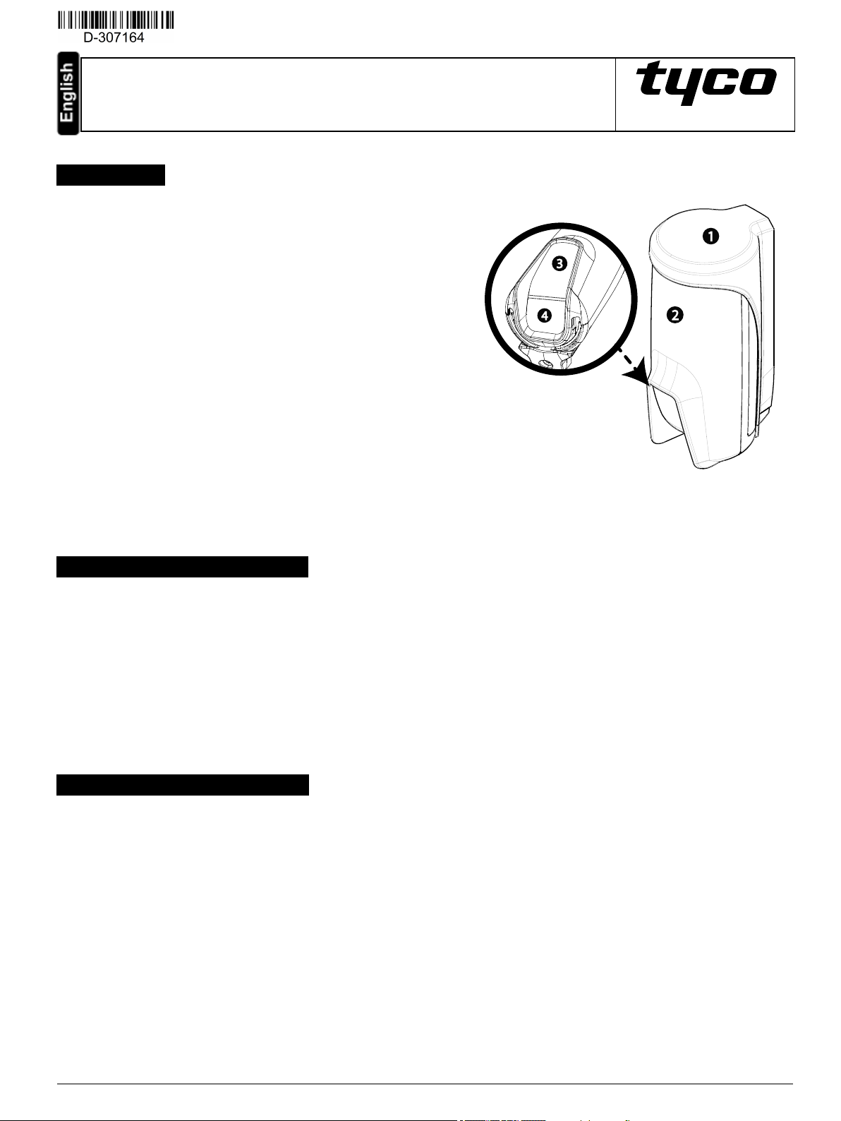
1. Bracket
2. Device
3. Indication LED
4. PIR optical window
2. Installing the MP-902 PG2
Installation Instructions
Figure 1- MP-902 PG2
Warning ! Do not partiallyor completelyobscure the detector’sfield of view. Do not installthe device close to tree branches as weather conditions can
cause movement.
Note: Alarms triggered by conditionssuch as weather, blowing leaves and branches, or any related environmental conditions, must be considered
when installing the detector.
Warning ! To complywith FCC and ISED Canada RF exposure compliance requirements, locate the PIR detector at a distance of at least 20 cm from
all persons during normal operation. The antennas used for thisproduct must not be co-located or operated in conjunction with any other antenna or
transmitter.
Note: Install and use the MP-902 PG2 wireless outdoor curtain PIRdetector with anti-masking within an environment that provides pollution degree
max 2 and overvoltages category II in NON HAZARDOUS LOCATIONS. The equipment is designed to be installed by qualified service persons only.
Note: Install the MP-902 PG2 in accordance with the Standard for Installation and Classification of Burglar and Holdup Alarm Systems, UL 681.
3. Mounting the MP-902 PG2
To mount the MP-902 PG2, complete the following steps:
1. Mark and drillat least two holesin the mounting bracket (see figure 2 and 3).
Note: To install tamper protection on the detector, mark and drill one hole for the tamper protection (hole number 3, figure 2) and two holes in
the other available slots(number 1 and 2, figure 2).
2. Fasten the bracket to the wallsurface with the screws (see figure 4).
3. Insert the batteries ( see '6.Inserting or replacing the batteries') and close the battery cover.
4. Position the detector in order to cover the protected area by inserting the top of the detector into the preferred slot (see figure 5 and 6) .
Note: Thiswill start the tamper self-calibrating procedure, which can be seen bya yellow blinking LED.
Note: When the device is inserted into the bracket, it can be rotated again to a more exact position (see figure 7, number 1).
5. While the LED is blinking, fasten the detector to the bracket by tightening the bottom screw (see figure 7, number 2).
Note: If the yellow LED stops blinking before the screw is tightened adequately, r emove the detector from the bracket and wait three
seconds. Now repeat the self-calibrating procedure in step 4.
D-307164 MP-902 PG2 Installation Instructions 1
Page 2
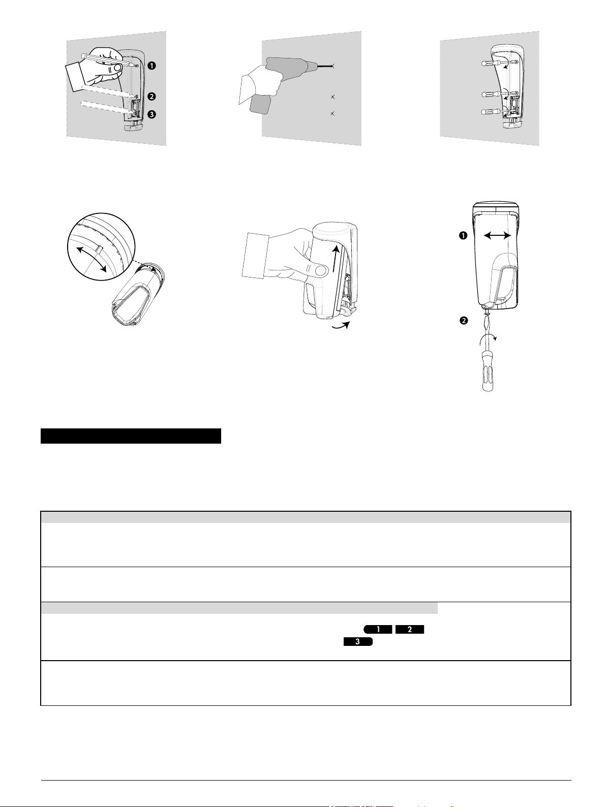
Figure 2 -
Marking screw holes
Figure 3 -
Drilling screw holes
Figure 4 -
Fastening the bracket
Figure 5 -
Rotatio n slot
Figure 6 - Slottin g int o device
Figure 7 -
Closing th e bracket
4. Enrolling the MP-902 PG2
Refer to the PowerMaster panel installer guide and follow the procedure under the “02:ZONES/DEVICES” option of the installer menu.
Note: For UL/ULC listed installations use only in conjunction with UL/ULC listed control panels.
Note: When enrolling the MP-902 PG2 detector to PowerMaster panels with version 19.4 or lower, the detector will be enrolled asoutdoor PIR motion
detector (ID 130-xxxx) and labeled 'Motion Outd.' in the panel.
To enroll the device, enter the installation menu and complete the following steps:
Step 1 Step 2 Step 3 Step 4
Enter the Installer menu and select
“02:ZONES/DEVICES”
02:ZONES/DEVICES
Step 5 Step 6 Step 7
Configure Location, Zone Type &
Chime parameters
Z0x.LOCATION
Z0x.ZONE TYPE
Z0x.SET CHIME
ðmeans scroll wwand select OK.
Note: If the detector is already enrolled you can configure the detector parameters and assign par titions as in '5. Configuring the detector parameters'.
Note: PARTITIONS will appear onlyif PART ITIONING was previouslyenabled in apanel that supports the Partitioning feature (for further details, see
'Partitioning' in the PowerMaster Installer Guide).
Select "ADD NEW DEVICE"
See Note 1
ð
ADD NEW DEVICES
MODIFY DEVICES
Enter PARTITIONS.
See Note 2
ð
Z0x/PARTITIONS
Pullthe enrollment tab / insert the
batteries topower on the device
and begin the auto-enrollment
process (or enter the device ID).
ð
ENROLL NOW or
6
Table 1 - Enrolling the MP-902 PG2
ENTR ID: XXX-XXXX
Assign partitions to the detector by
pressing the ,
and/or buttons on the
ð
Z0x:P1n-- P2....P3n
panel
Select a detector number for the
new detector
ð
Z0x: OutCurtain
ID No. 129-XXXX
ð
ð
D-307164 MP-902 PG2 Installation Instructions 2
Page 3
5. Configuring the detector parameters
5.1. Modifying the device
Enter the DEVICE SETTINGS menu and follow the configuration instructionsfor the MP-902 PG2 detector as described in the table.
Option Con fig uring instructions
Alarm LED Define whether or not the alarm LED indication will be activated.
Optional settings: LED ON (default) and LED OFF.
PIR range Select one of the three ranges, according to the type of installation.
See 'Setting the detector range'
Outdoor
anti-mask
Alarm
hours
Alarm
direction
Enable or disable the outdoor anti-masking feature.
Optional settings: Disabled (default) and Enabled.
Define whether motion alarms are always enabled or only when dark (at night).
Optional settings: Day and night (default) and Night only.
Note: For UL/ULC installation, the alarm hours feature when enabled for night protection should only be used as supplemental
protection to the protection covering the protected area.
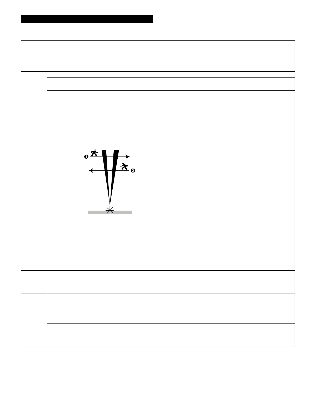
Define the detection direction.
Note: Available in PowerMaster panelsVer sion V20.2 and higher only.
Note: The alarm direction function can r educe the probabilityof false alarms by more than half when the detector is installed alongside
a door or gate as the device can differentiate between property inhabitants exiting and potential intruders entering the premesis.
Optional settings:
Both ( default), Left t o right, Right to left.
Note: See figure 8 for alarm direction diagram.
1. Right to left
2. Left to right
Note: The right and left directions refer to the installer's point of
view while observing the detector in its fixed position.
Figure 8 - Direction d etection
VERY HOT
> 35 °C [
>95 °F]
COLD <19
°C [<66 °F]
*
FREEZING
< 7 °C [<45
°F]*
FREEZER
> - 10 °C [
<14 °F]*
Disarm
activity
Note: The temperature must pass beyond the threshold for the required duration in order to generate an alarm or restore transmission.
Note: The user can give access to the installer remotely enable or disable the indication LED.
Define whether or not the control panel will report a "very hot" alert when the temperature rises above the “Threshold” value (default
35 °C / 95 °F) for at least the duration specified in the “Wait before alert” value (default 10 minutes). Alert restore willoccur when the
temperature drops 1 °C / 1.8 °F below “Threshold” for at least the duration of “Wait before restore” (default 10 minutes).
Optional settings: See table 3
Define whether or not the control panel will report a "cold" alert when the temperature drops below the “Threshold” value (default 19
°C / 66 °F) for at least the duration specified in the “Wait before alert” value (default 10 minutes). Alert restore will occur when the
temperature rises1 °C / 1.8 °F above “Threshold” for at least the duration of “Wait before restore” (default 10 minutes).
Optional settings: See table 3
Define whether or not the control panel will report a "freezing" alert when the temperature drop below the “Threshold” value (default 7
°C / 45 °F) for at least the duration specified in the “Wait before alert” value (default 10 minutes). Alert restore will occur when the
temperature rises1 °C / 1.8 °F above “Threshold” for at least the duration of “Wait before restore” (default 10 minutes).
Optional settings: See table 3
Define whether or not the control panel will report a "freezer" alert when the temper ature rises above the “Threshold” value (default 10 °C / 14 °F) for at least the duration specified in the “Wait before alert” value (default 30 minutes). Alert restore willoccur when the
temperature drops 1 °C / 1.8 °F below “Threshold” for at least the duration of “Wait before restore” (default 30 minutes).
Optional settings: See table 3
Define whether or not to set the activitytime during disarm.
Optional settings:
NOT Active (default)
YES – no d elay, YES + 5 second delay, YES + 15 s delay, YES + 30 s delay, YES + 1 minute delay, YES + 2 m delay, YES +
5 m delay, YES + 10 m delay, YES + 20 m delay, YES + 60 m d elay
Table 2 - Modifying the device
D-307164 MP-902 PG2 Installation Instructions 3
Page 4

Each of the four temperature alerts (Very Hot, Cold, Freezing, and Freezer) can beconfigured with the settingsdescribed in Table 3:
Option Con fig uring instructions
Threshold Displays the last saved threshold and provides the installer with the abilityto change the value using the Back / Next buttons.
Disable /
Defines whether the panelwill report the alert.
Enable
Wait before
alert
Wait before
restore
Defines the time the panel waits before reporting the alert when temperature exceeds the defined default. The 'Wait before alert"
time valuesare:
l Immediately
l 1 minutes
l 2 minutes
l 10 minutes
l 15 minutes
l 20 minutes
l 30 minutes
Defines the time the panel waits before reporting on restoration of the alert when the temperature returns to the threshold range.
The 'Wait before restore" time values are:
l Immediately
l 1 minutes
l 2 minutes
l 10 minutes
l 15 minutes
l 20 minutes
l 30 minutes
Table 3 - Temperature config uration settings
5.2. Setting the detector range
PowerMaster panel
version
V20.2 and higher MP-902
V19.4 and lower TOWER-20AM
Detection ranges Select 3 m, 5 mor 8 m( see number 2, figure 9)
Device Type Rang e setting menu locatio n and o pt ion s Rang e
02: ZONE / DEVICES > ... > DEVICE SETTINGS >
S.OutCurtain
ID: 129-xxxx
PIR RANGE >
Long
Medium
Short
8 m
5 m
3 m
02: ZONE / DEVICES > ... > DEVICE SETTINGS >
Motion Outd.
ID: 130-xxxx
PIR SENSITIVITY >
High
Low
One r egion
8 m
3 m
8 m
Figure 9 - Detection pattern
Table 4 - Set tin g the detector range
1. 2.1 m (6.89 ft )
2. 8 m (26.25 ft )
3. 0.75 m (2.46 ft )
4. 1.9 m (6.23 ft )
5. 0.25 m (0.82 ft )
Note: The symbol signifies the
detector point of view and the
beginning of the PIR curtain.
D-307164 MP-902 PG2 Installation Instructions 4
Page 5

6. Inserting or replacing the batteries
To mount the MP-902 PG2, complete the following steps:
1. To separate the detector from the mounting bracket, unscrew the bottom screw (see F igure 10) and remove the detector fr om the br acket
(see Figure 11).
2. Open the battery cover by pressing on the snap located at the top of the battery cover (see F igure 12).
3. Insert the batteries while observing polarity (see Figure 15, number 3).
Note: If the batteries are already installed, pull the battery tab while holding the batteries in place (see Figure 13).
4. Close the battery cover untilyou hear a click(see Figure 14) and insert the device into the bracket (see steps 4 and 5 in '3. Mounting the MP-
902 PG2').
Note: It is recommended to wait about 1 minute after battery removal before inserting the new batteries.
Caut ion! There isa risk of explosion if the batteries are replaced by an incorrect type. Dispose of used batteriesaccording to the manufacturer's
instructionsand according to local rules and regulations.
Figure 12 - Opening t he battery cover
Figure 11 - Removing the detector from bracket
Figure 10 - Unscrewing
the bracket
Figure 15
1. Pet immunity selector
(1) Pet < 18 kg
(2) Pet < 9 kg
(3) No function
(4) No pet immunity
Note: Setting number '3' in
the pet mask selector has no
function.
2. Enrollment button
3. Battery polarity
Figure 13 - Pulling the battery tab Figure 14 - Closing the battery cover
Figure 15 - Pet immunity, battery polarity, and bu tton en rollment
D-307164 MP-902 PG2 Installation Instructions 5
Page 6

7. Local diagnostic test / Walk Test
Before permanently mounting the device, temporarilymount the device and perform a walk test. Perform a walk test of the coverage area at least once
a week to ensure that the detector isworking correctly.
After inserting the batteries or closing the battery cover, the detector will automatically enter a stabilityperiod where the LED flashesred for 90 seconds.
When you walk- test the coverage area, the LED lights red each time your motion isdetected, followed by three LED blinks. The color of the three LED
blinks indicates the received signal strength. The following table indicates the received signal strength.
LED response Reception
3 Green blinks Strong
3 Orange blinks Good
3 Red blinks Poor
No blinks No communication
Table 5 - Walk test signal strength indication
Important! Reliable reception must be confirmed. T herefore, "poor" signal strength is not acceptable. If you receive a "poor" signal from the device,
relocate it and re- test until a "good " or "strong" signal strength is r eceived.
In walk-test mode, regardless of the LED selection status, the LED lights upon every motion detection. Walk-test the coverage area by walking across
the far end of the coverage pattern inboth directions. The red LED lights each time your motion is detected followed by steady LED signal strength
indication. After 15 minutes the detector automaticallyenters normal mode.
The MP-902 PG2 can be configured to detect movement with the following settings:'Left to right', 'Right to left', and 'Both'. For more information, refer to
Alarm direction in '5. Configuring the detector parameters'
Note: For detailed diagnosticstest instructions refer to the control panel installer guide.
8. LED operation
LED Indicatio n Event
Red LED blinks Stabilization (Warm-up 90 seconds)
Red LED on 0.2 seconds Tamper open / close
Red LED on 2 seconds Intruder alarm
Yellow LED on AM detection, diagnosticmode
Yellow LED blinks slowly (0.2 seconds on, 30 seconds off) AM detection, normal mode
Yellow LED blinks Back tamper self-calibration
Table 6 - L ED indicatio n sign ificance
9. Temperature Display
For instructions on displaying the temperature and light of zones on the correct panel as measured by the MP-902 PG2, refer to '6.2 Conducting a
Periodic Test' in the PowerMaster installer guide.
10. Specifications
GENERAL
Detector type Specialtwo-channel PIR
OPTICAL
Lens data Mirror type, one curtain mirror
Detector mirror max.
coverage
Detection ranges
ELECTRICAL
Power supply Type C
Internal battery Two 3 V lithium battery, type CR-123A. For UL installations, use Panasonicand GPonly
Nominal battery
capacity
Battery life (typicaluse) Minimum 1year. Typicaluse, 3 years (not verified byUL)
Low battery threshold 4 V
Battery power test
Curr ent consumption 30 μA average quiescent, maximum 150 mA (during transmission)
FUNCTIONAL
Alarm period 2 seconds
Pet immunity Up to 18 kg (40 lb)
Pet configurations No pet / Pet < 9 kg / Pet < 18 kg
Up to 8 m ( 26.2 ft) /6 °
1450 mAh
Performed immediately upon battery insertion and periodicallyevery several hours. The power supplyis type C in accordance
with EN50131-6 Documentation - Clause 6.
D-307164 MP-902 PG2 Installation Instructions 6
Page 7

WIRELESS
Frequency
Max Tx power 10 dBm @ 433MHz, 14 dBm @ 868MHz
Communication
protocol:
Supervision Signaling at 256 second intervals
Tamper alert Reported when a tamper event occurs and in anysubsequent message, until the tamper switch is restored.
MOUNTING
Mounting type: Wall mounting
Mounting height: 1.8 - 2.4 m (5.9 - 7.9 ft)
Horizontal adjustment: -90 °to +90 °, in 10 ° steps
ENVIRONMENTAL
RF immunity 20 V/m up to 1000 MHz, 10 V/m up to 2700 MHz
Operating
temperatures
Humidity
Storage temperatures -35 °C to 60 °C (-31 °F to 140 °F)
PHYSICAL
Size(diameter) 145 mm x 71 mm x 62 mm
Weight ( with battery) 283 g
Color White
Europe and r est of world: 433-434 MHz, 868-869 MHz USA: 912-919 MHz
Onlydevicesin frequency band 915 MHz ar e UL/ULC listed.
PowerG
- 35 °C to 60 °C (-31 °F to 140 °F)
For UL / ULC installation, evaluated to 66°C
Average relative humidity of up to approximately 75 %non-condensing. For 30 days per year the relative humidity may vary
between 85 % and 95 % non-condensing.
For UL installations: 5 %to 93 % with no condensation
11. Compatible receivers
This device can be used with PowerMaster panelsthat usePowerG technology.
Note: For UL installations, the detector is for use with UL listed control units only.
Note: Only devices operating in band 912-919 MHz are UL / ULC listed.
12. Compliance with standards
The MP-902 PG2 complies with the following standards:
Europe: EN 300220, EN 301489, EN 50130-4, EN 62368-1, EN 60950-22, EN 50131-2-2 Grade 2, Class IV IP55,
EN 50130-5, EN 50131-6 Type C.
The PowerG peripheral devices have two-way communication functionality, providing additional benefits as described in
technical brochure. This functionality has not been tested to comply with the respective technical requirements and should
therefore be considered outside the scope of the product's certification.
Hereby, Visonic Ltd. declares that the radio equipment type MP-902 PG2 is in compliance with Directive
2014/53/EU. The full text of the EU declaration of conformity is available at the following internet address:
http://www.visonic.com/download-center.
USA: FCC- CFR 47 Part 15
Canada: IC RSS - 247
USA: UL639
Canada: ULC-S306
This device complieswith Part 15 of the FCC Rules and with Industry Canada license-exempt RSS standard(s). Operation is subjectto the following
two conditions: (1) This device may not cause harmful interference, and (2) this device must accept any interference received, including interference
that maycause undesired operation.
Le present appareil est conforme auxCNR d'Industrie Canada applicables aux appareilsradio exemptsde licence. L'exploitation est autorisee aux
deux conditionssuivantes :(1) l'appareil ne doit pas produire de brouillage, et (2) l'utilisateur de l'appareildoit accepter tout brouillage radioelectrique
subi, meme sile brouillage est susceptible d'en compromettre le fonctionnement.
the
To complywith FCC Section 1.1310 for human exposure to radio frequency electromagnetic fields and IC requirements, implement the following
instruction:
A distance of at least 20cm. between the equipment and all persons should be maintained during the operation of the equipment.
Le dispositif doit êtr e placé à une distance d'au moins 20 cm à partir de toutes les personnes au cours de son fonctionnement normal. Lesantennes
utilisées pour ce produit ne doivent pasêtre situésou exploitésconjointement avec une autre antenne ou transmetteur .
NOTE: Thisequipment hasbeen tested and found tocomply with the limits for a Class B digital device, pursuant to part 15 of the FCC Rules. These
limits are designed to provide reasonable protection against harmful interfer ence in a residential installation. This equipment generates, uses and can
radiate radio frequency energy and, if not installed and used in accordance with the instructions, may cause harmful interference to radio
communications. However, there is no guarantee that interference will not occur in a particular installation. If this equipment does cause har mful
D-307164 MP-902 PG2 Installation Instructions 7
Page 8

interference to radio or television reception, which can be determined by turning the equipment off and on, the user is encouraged to try to corr ect the
interference by one or more of the following measures:
l Reorient or relocate the receiving antenna.
l Increase the separation between the equipment and receiver.
l Connect the equipment into an outlet on a circuitdifferent from that to which the receiver is connected.
l Consult the dealer or an experienced radio/TV technician for help.
- This Class B digital apparatus complies with Canadian ICES-003.
- Cet appareil numerique de la classe B est conforme a la norme NMB-003 du Canada.
WARNING! Changes or modifications to thisunit not expresslyapproved bythe party responsible for compliance could void the user’s authority to
operate the equipment.
W.E.E.E. Product Recycling Declaration
For information regarding the recyclingof this productyou must contact thecompany from which you orignially purchased it. If you
are discarding this product and not returning it for repair then you must ensure that it is returned as identified by your supplier. This
product is not to be thrown away with everyday waste.
Directive 2002/96/EC Waste Electrical and Electronic Equipment.
EMAIL: info@visonic.com
INTERNET: www.visonic.com
VISONIC LTD. 2018D-307164 MC-902 PG2 REV. 0, (08/18)
D-307164 MP-902 PG2 Installation Instructions 8
 Loading...