

Page 1
D-307080 MP-862 Installation Instructions 1
1. Introduction
The MP-862 is a smart wireless ceiling PIR presence/security detector (selected mode) that creates a 360° coverage area to detect the movement of intruder s in indoor areas.
The detector has the following features.
l Presence detection mode - active 15 minutes after installation (power-up).
l Built-in link quality indicators eliminate the need for the installer to physically approach the control panel and reduce installation time.
l Temperature and light measurement and reporting.
l Tamper protection.
l PowerG two-way Frequency Hopping Spread Spectrum FHSS-TDMA technology.
l The Advanced True Motion Recognition™ algorithm (patented)distinguishes between the tr ue motion of an intruder and any other disturbances
which may cause false alarms.
NOTE: For UL installations, the detector isfor use with UL listed control unitsonly.
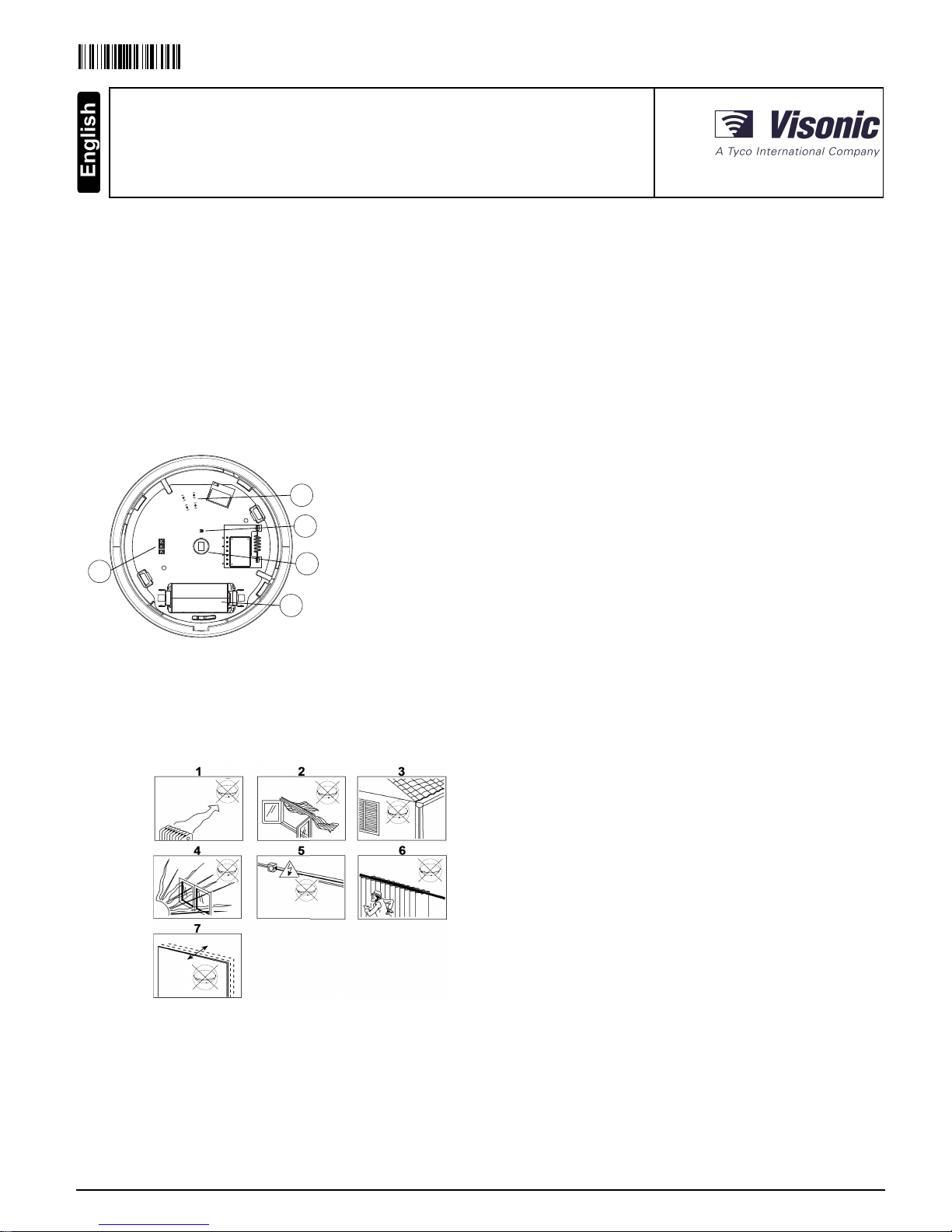
D
A
B
C
E
Fig ure 1. Internal view
A Tamper protection
B Light sensor
C Pyro sensor
D Battery
E LEDs
2. Installation
2.1. Installation tips
Use the following as a guide for locating a suitable mounting location.
1. Keep away from heat sources.
2. Do not expose to air drafts.
3. Do not install outdoors.
4. Avoid direct sunshine.
5. Do not install near high voltage electricallines.
6. Do not install behind partitions.
7. Mount on a solid stable surface.
Fig ure 2. Gen eral Guid elin es
WARNING! Do not partially or completely obscure the detector’s field of view.
WARNING! T o comply with FCC and ISED Canada RF exposure compliance requirements, the PIR detector should be located at a distance of
at least 20 cm from all persons during normal operation. The antennas usedfor this product must not be co-located or operated in conjunction
with any other antenna or transmitter .
NOTE: The MP-862 Wireless ceiling PIR presence/securitydetector shall be installed and used within an environment that provides the pollution
degree max 2 and overvoltages category II in NON HAZARDOUS LOCATIONS. The equipment is designed to be installed only by qualified servicepersons.
D-307080
MP-862
Wireless ceiling PIR presence/security detector
Installation Instructions
Page 2
NOTE: MP-862 shall be installed in accordance with the Standard for Installation and Classification of Burglar and Holdup Alarm Systems, UL
681.
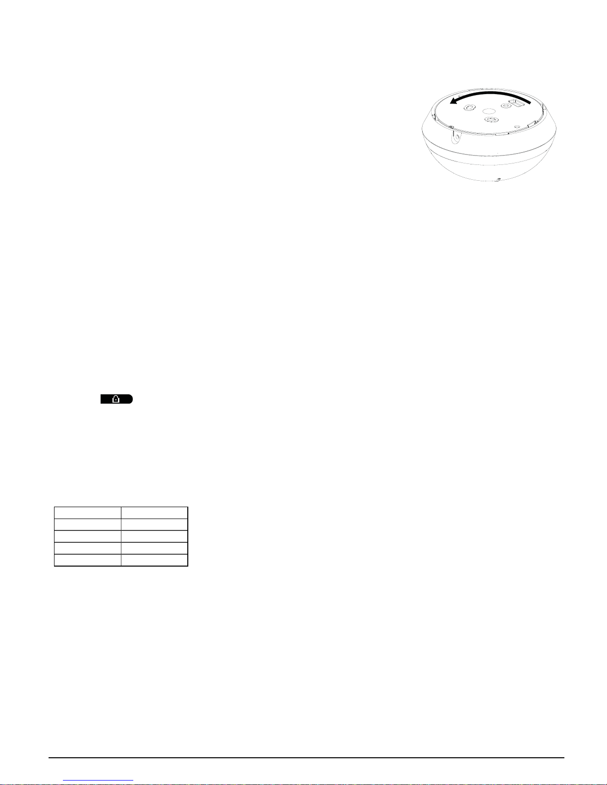
2.2. Inserting or replacing the battery
If the battery isalready installed, pull the activation strip that protrudes from the back of the detector.
1. To separate the detector from the mounting bracket, rotate the bracket anticlockwiseand pullit fr om
the detector.
2. Insert the battery while observing polarity.
3. Align the bracket tabs with the detector slots and rotate the detector clockwise to verify that it is securely
attached.
Fig ure 3. Removing the bracket
NOTE: It is recommended to wait about 1 minute after battery removal before inserting the new battery.
Caution! Risk of explosion if battery is replaced byan incorr ect type. Dispose of used batteries according to the manufacturer's instructions and
according to localrules and regulations.
2.3. Enrollment
Refer to the PowerMaster panel’s installer guideand follow the procedure under the “02:ZONES/DEVICES” option of the Installer Menu.
NOTE: For UL/ULC listed installations use onlyin conjunction with UL/ULC listed control panels: PowerMaster-10 and PowerMaster-30 PG2.
To enroll the device enter the Installation menu and do as follows:
1. From the Installation menu, select 02:ZONES/DEVICES and click OK.
2. Select ADD NEW DEVICES and click OK. Panel displays: <ENROLL NOW or ENTER ID:xxx-xxxx>
3. Enter ID:XXX-XXXX (the number of the device that isprinted on the label), -OR- insert the battery to power on the device.
4. To change the Zone/Devicenumber, click the arrow button or type the zone number and then click OK.
5. To configure the location, zone type and chime parameters, select Z14.LOCATION, Z14.ZONE TYPE and Z14.SET CHIME and select desired
settings.
6. Select one of the following options.
a. Continue to configure the device.
b.
Select and then clickOK to exit.
2.4. Walk testing
Before permanently mounting any wireless device,temporarily mount the device and perform a walktest. Perform a walktest of the coverage
area at least oncea year to ensure that the detector is working corr ectly.
After inserting the battery or closingthe device, the detector will automatically enter a stability period where the LED flashes RED for 90 seconds.
Walk test the coverage area, the LED lights red each time your motion isdetected followed by3 LED blinks. The color of the 3 LED blinks indicate
the received signal strength. In walk-test mode, regardless of the LED Selection status, the LED lights upon every motion detection. After 15
minutes the detector automatically enters normal mode.
The following table indicates the received signal strength.
LED Response Signal Strength
Green LED blinks STRONG
Orange LED blinks GOOD
Red LED blinks POOR
No blinks No communication
IMPORTANT! Only GOOD or STRONG signalstrengths are acceptable. If you receive a POOR signal from the device, re-locate it and re-test
until a GOOD or STRONG signal isr eceived.
NOTE: For UL/ULC installations, onlySTRONG signal levels are acceptable. After installation verify the product functionality in conjunction with
the compatible control panels PowerMaster-10 and PowerMaster-30 PG2.
NOTE: For detailed Placement instructions refer to the control panel reference manual.
Walk-test the cover age area by walking across the far end of the coverage pattern in both directions. T he red LED lights each time your motion is
detected followed by a steady LED signal strength indication.
2.5. Mounting the device
1. Mark and dr illtwo holes in the mounting surface. If you install tamper protection on the detector, mark and drill one hole for the tamper protection and one hole for one of the other available slots.
2. Fasten the bracket to the mounting surface with the two screws.
3. Align the br acket tabs with the detector slots and rotate the detector clockwise. Verify that it is securely attached.
4. Fasten the detector to the br acket with the screw.
D-307080 MP-862 Installation Instructions 2
Page 3
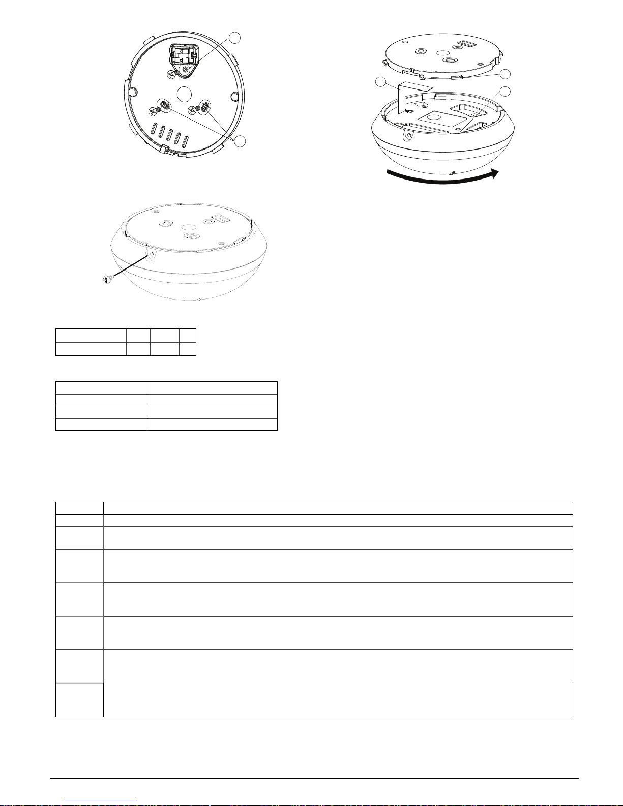
A
B
Fig ure 4. F ast ening the b racket
D
E
C
Fig ure 5. Att ach ing the detect or
Fig ure 6. F ast ening the d et ector
A Tamper protection
B Bracket screw slots
C Isolation strip
D Bracket tabs
E Detector slots
The following table outlines the detection distance in relation to the mounting height.
Height 2 m 3 m 4 m
Detection distance 3.1 m 3.75 m 5 m
2.6. LED Operation
LED Indications Event
Red LED blinks Stabilization (war m- up 90 seconds)
Red LED on 0.2 seconds T amper open/close
Red LED on 2 seconds Intruder alarm
3. Temperature display
4. Configuring the Detector Parameters
Enter the DEVICE SETTINGS menu and follow the configur ation instructions for the deviceas described in the following table.
Option Con fig uring Instructions
Alarm LED Define whether or not the alarm LED indication will be activated. Optional settings: LED ON (default) and LED OFF .
Event
Counter
Define whether an alarm willbe activated upon continued motion (low sensitivity) or upon a single alarm event (high sensitivity).
Optional settings: LOW sensitive (default) and HIGH sensitive.
DISARM
Activity
Define whether or not to set the activity time during disarm. Optional settings: NOT Active (default), YES – no delay, YES+ 5s
delay, YES + 15sdelay, YES + 30s delay, YES + 1m delay,YES + 2m delay, YES+ 5m delay, YES + 10m delay,YES + 20m delay
and YES+ 60m delay.
VERY HOT
> 35°C [
>95°F]
Define whether or not the control panel willrepor t a "very hot" alert when the temper atur e risesabove 35°C (95°F) for at least 10
minutes. Alert restor e willoccur when the temperature drops below 34°C ( 93°F) for the duration of 10 minutes. Optional settings:
Disable (default) or Enable
COLD <
19°C [
<66°F]*
Define whether or not the control panel willrepor t a "cold" alert when the temper ature drops below 19°C (66°F) for at least10
minutes. Alert restor e willoccur when the temperature rises above 20°C (68°F) for the duration of 10 minutes. Optional settings:
Disable (default) or Enable
FREEZING
< 7°C [
<45°F]*
Define whether or not the control panel willrepor t a "freezing" alert when the temperatur e drops below 7°C (45°F) for at least 10
minutes. Alert restor e willoccur when the temperature rises above 8°C (48°F) for the duration of 10 minutes. Optional settings: Disable (default) or Enable
FREEZER >
-10°C [
<14°F]*
Define whether or not the control panel willrepor t a "freezer" alert when the temperature risesabove -10°C (14°F) for at least 30
minutes. Alert restor e willoccur when the temperature drops below -11°C (12°F) for the duration of 10 minutes. Optional settings:
Disable (default) or Enable
NOTE: The temperature mustpass beyond the threshold for the required duration in order to generate an alarm or restore transmission.
NOTE: The user can giveaccess to installer to remotely enable or disable the indication LED.
D-307080 MP-862 Installation Instructions 3
Page 4

5. Specifications
GENERAL
Detector T yp e
One pyroelectric sensor operating in a dual separated configuration
OPTICAL
Len s Data
Fresnel type lens.
Number of beams: 72
Max. coverage
Ø10 m/360° at the maximum installation height of 4 m
ELECTRICAL
Power Supply: Type C
Int ernal Batt ery
3V Lithium battery, type CR-123A. For UL installations,use Panasonic and GP only
Nominal Battery Capacity: 1450 mAh
Battery Life (typical use)
Minimum 1 year. For typicaluse (security mode), 5 years (not verified byUL).
Low Battery Th resh old: 2.4 V
NOTE: Inability to connect with wireless network, or wireless link qualityno higher than 20% maysignificantlyreduce the expected battery life.
Battery Power Test
Performed immediately upon batter y insertion and per iodically after every several hours.
The power supplyis typeC in accordance with EN 50131- 6 Documentation – Clause 6.
Current Consumption
20 μAaverage quiescent , maximum 150 mA (dur ing transmission)
Fig ure 7. Beam d ist ribut ion at 4 m Fig ure 8. Beam d ist ribut ion at 2.7 m
FUNCT IONAL
Alarm Period : 2 seconds
WIRELESS
Freq uency
Europe and rest of world: 433- 434 MHz,868- 869 MHz USA: 912- 919 MHz
NOTE: Only devices in frequency band 915 MHz are UL/ULC listed.
Max Tx Po wer
10 dBm@ 433MHz, 14 dBm @ 868MHz
Communicatio n Proto co l: Power G BW
Supervision : Signaling at 256 s intervals
Tamper Alert
Reported when a tamper event occurs and in any subsequent message, until the tamper switch is restored.
MOUNT ING
Heig ht: 2 m to 4 m
Installation Option s: Ceilingsurface
D-307080 MP-862 Installation Instructions 4
Page 5

ENVIRONMENT AL
RF Immunity
20 V/mup to 1000 MHz, 10 V/m up to 2700 MHz
Operating T emperatu res
-10 °C to 55 °C (14 °F to 131 °F).
NOTE: UL verified operation range 0 °C to 49 °C only.
Storage Temperat ures
-20 °C to 60 °C (-4 °F to 140 °F).
Humidity
Average relative humidity of up to approximately 75% non-condensing. For 30 days per year the relative humidity mayvary between 85% and
95% non-condensing.
For UL installations: 5% to 93% with no condensation
PHYSICAL
Size (diameter) : 10.6 cm
Weight (with b attery): 110 g ( 3.88 oz)
Color: White
COMPATIBLE RECEIVERS
6. Compliance With Standards
The MP-862 complies wi th t he following standards:
Euro pe: EN 30 02 20, EN 3 01 48 9, E N 50 13 0-4, EN 6 23 68 -1, EN 50 13 1-2-2 Grade 2, Class II, EN 501 30-5, EN 50 131-6 Ty pe C.
The Power G p eriph eral d evices ha ve tw o-w ay communica tion functio na lity, pr ovidin g add itio na l benefits as d escrib ed in th e technical bro chu re. Th is functio na lity ha s not b een tested to comply w ith
the respective techn ical req uir ements an d sho uld th erefor e be cons idered ou tside the scop e of th e pro duct' s certif icatio n.
Hereby , Vi so ni c Ltd. decl ares that th e rad io eq ui pment t yp e MP-86 2 is in co mpliance with Directive 20 14/5 3/ EU.
The full t ext o f the E U decl arati on of conformi ty is avail abl e at t he foll owing i nt ernet add ress :
http:/ /w ww.v is on ic.com/ do wnlo ad-cent er.
USA: FCC- CFR 47 Part 15
Canada: IC RSS - 247
USA: U L639
Canada: UL C-S3 06
Thi s device compli es w it h Part 15 of the FCC Rules and with In dust ry Can ada license-exempt RSS st and ard(s ). Operation i s subject to th e foll owin g two conditi ons: (1) Th is devi ce may n ot cause harmful i nt erference, and (2) t hi s device mus t accept any in terference recei ved , includi ng in terference t hat may cause un des ired
operat ion.
Le present app areil est con forme aux CNR d'Indust rie Canada appl icables aux apparei ls radi o exemp ts de l icence. L' exploit ati on es t autoris ee aux d eux co nd it io ns
suivantes :(1) l' appareil ne do it pas pro du ire de bro ui ll age, et (2 ) l 'u tilis ateur d e l'appareil doit accepter t ou t bro ui llage radio elect rique su bi , meme si l e brouill age
est s us cept ib le d'en compromet tre le fo nct io nn ement.
To comply w it h FCC Sect io n 1.13 10 for h uman exp os ure to rad io freq uen cy el ectro magnet ic fields and IC requ irements, implement t he foll owing i ns tru cti on :
A di st ance o f at least 20cm. between t he equ ip ment and al l p ersons sh ou ld b e maint ain ed d uri ng t he op erati on of t he equ ip ment.
Le di sp os it if d oi t être placé à une di stance d'au moins 20 cm à partir de t ou tes l es pers on nes au cou rs de son fo nct io nn ement normal. Les antennes ut il is ées p ou r ce
prod ui t ne doivent p as être si tués ou exploit és co nj oi nt ement av ec u ne autre anten ne ou t rans mett eur.
NOTE: Th is equipment has been tested and foun d to comply wit h the li mit s for a Class B d igital dev ice, p urs uan t to p art 15 of th e FCC Rul es. Thes e l imits are
desi gned to p rov id e reasonable prot ection agai ns t harmful i nt erference i n a resi den ti al i ns tal lation. This equipment generat es, uses and can radi ate radio frequen cy
energy and, if no t installed and u sed i n accordance w it h the in st ruct io ns , may cau se harmful i nt erference to radio co mmuni cations. Ho wever, there is no g uarantee t hat
interference wil l no t occur i n a parti cul ar in st all ati on . If t hi s equ ip ment do es caus e h armful in terferen ce to rad io o r televisi on reception, wh ich can b e determi ned by
turning th e equi pmen t o ff and on, the u ser is encouraged to try t o correct t he in terferen ce by o ne or more of t he fol lo wi ng measu res:
l Reorient o r relocate th e receiving anten na.
l Increase th e separation between the equ ipment and receiver.
l Conn ect th e equipm ent into an o utlet on a circuit d ifferent from th at to which the receiver is connected.
l Cons ult the dealer or an experienced radio/TV technician for h elp.
Thi s Class B di gi tal apparatus compl ies wit h Canadian ICES-003 .
Cet apparei l numerique de l a classe B es t conforme a l a no rme NMB-003 du Canada.
WARNING! Changes o r modifi cati on s to th is u ni t not ex pressl y ap pro ved by the p arty responsible for co mpliance coul d vo id the us er’s aut ho rit y t o o perate the
equi pmen t.
W.E.E.E. Pro du ct Recycli ng Decl arati on
For informati on regarding t he recycl in g o f this product you must contact the co mpany fro m w hi ch you ori gn ial ly pu rchas ed i t. If you are d is cardi ng th is
prod uct and no t returni ng it for repair then you must ensu re that i t i s returned as i den ti fied by your su ppli er. This p roduct is not to b e th rown away wi th
everyd ay wast e.
Direct ive 2002 /96/ EC W ast e Elect rical and E lect ron ic E qu ip ment.
WARRANTY
Vis on ic Li mit ed (the “Manu factu rer") warrant s this p roduct on ly (the "Prod uct ") t o t he ori gi nal purchas er on ly (the “Purchaser”) agai ns t defective workmans hi p and
material s und er n ormal use of the Product for a peri od of t wel ve (12 ) mo nt hs from the date o f shipment by t he Manu factu rer.
Thi s Warran ty is abs ol ut ely con di ti on al u po n th e Produ ct having been pro perl y install ed, main tai ned and o perat ed u nd er co nd it io ns of normal us e in accordance w it h
the Manu factu rers recommended i ns tallati on an d operati on instructi on s. Products w hi ch have become d efecti ve fo r an y other reaso n, accordi ng to th e Manufacturers d is cretion, such as impro per i nstallati on , fai lu re to fol low recommend ed instal lat io n and operati onal i ns tru cti on s, neglect, will ful damage, misuse or v and ali sm, accid ent al
damage, al terat io n o r tamperi ng , or repai r b y any on e o th er t han t he manu factu rer, are no t cov ered by t hi s Warran ty .
There is absolutely no warranty on so ftw are, and al l software products are so ld as a user l icense u nd er t he terms o f th e s oft ware license agreement included wit h su ch
Produ ct."
The Manu factu rer does not rep resen t t hat thi s Prod uct may not b e compro mised and /o r ci rcumvented or t hat t he Prod uct wi ll prevent any death an d/ or pers onal i nj ury
and/ or damage to property res ul ti ng from bu rgl ary, robbery, fire or o th erwi se, or t hat the Pro duct wil l i n all cases pro vi de adequ ate warni ng o r prot ecti on . The Product,
prop erly instal led and mai nt ain ed, on ly reduces th e risk of su ch even ts wit ho ut warn in g and i t i s not a guarant ee or i ns uran ce th at such even ts w il l not o ccur.
Cond it ions to Void Warranty : This warranty ap pl ies only to d efects i n parts and work mansh ip relat ing to n ormal use of the Products. It d oes n ot cover:
* damage incurred in sh ip pi ng or h and li ng ;
* damage caus ed by d is ast er s uch as fire, fl oo d, w in d, earthquak e or l ig ht ni ng ;
* damage du e to cau ses b eyond the control o f th e Sel ler su ch as exces si ve vol tage, mechanical shock or w ater damage;
D-307080 MP-862 Installation Instructions 5
Page 6

* damage caus ed by u nau th ori zed attachment, alterat io ns , modificat io ns o r forei gn ob ject s bei ng used wit h or in con ju nct io n wit h th e Produ cts ;
* damage caus ed by p erip heral s (u nl ess such peripherals were su pp li ed by t he Sell er;
* defect s caused b y failu re to pro vi de a s ui table in st all ati on env iro nment for the pro ducts;
* damage caus ed by u se of t he Product s for pu rpo ses ot her th an th os e fo r whi ch they were des ig ned ;
* damage from imp rop er main ten ance;
* damage aris ing ou t of an y ot her abu se, mish and li ng or improp er app li cati on of t he Products.
Items No t Cov ered by Warranty: In add it io n to t he i tems wh ich v oi d the Warrant y, t he fol lowi ng items sh all n ot be covered b y Warran ty : (i ) freig ht cos t to th e repair
centre; (i i) cus to ms fees, t axes , or VAT t hat may b e due; (iii) Products whi ch are n ot i dentified wi th th e Sel ler' s prod uct l abel an d lo t n umber or serial nu mber; (iv)
Produ cts di sassembled or repaired i n such a manner as t o adversely affect p erformance or prevent adeq uat e in sp ecti on or t est in g to v erify an y warranty clai m. Acces s
cards or tags ret urn ed fo r replacement under warran ty wi ll be credi ted or rep laced at t he Sell er's option.
THIS WARRANTY IS EXCLUSIVE AND EXPRESSLY IN LIEU OF AL L OT HE R WA RRANT IES, OBLIGAT IONS O R LIABILITIES, WH ET HER WRITT EN,
ORAL, EX PRESS OR IMPLIE D, INCLUDING ANY W ARRAN TY OF MERCHANTA BILITY OR FITNE SS FOR A PARTICULA R PURPOSE, O R O TH ERWISE . IN
NO CASE SHALL T HE MAN UFACTURER BE L IABLE TO AN YONE FOR ANY CONSE QUE NT IAL O R IN CIDENTA L DAMAGES FOR BREA CH O F THIS
WARRAN TY OR ANY OTHER WARRANTIES WHATSO EVER, AS AFORESAID.
THE MANUFA CTURE R SHALL IN NO E VENT BE LIA BLE FOR ANY SPECIAL , INDIRE CT, INCIDENT AL , CO NSEQ UE NTIAL OR PUN ITIV E D AMAG ES O R
FOR L OSS, D AMAG E, OR E XPENSE, INCLUD ING LOSS OF USE , PROFITS, REVE NUE , OR GO ODWILL , DIRECTLY OR INDIRE CTLY ARISING FROM
PURCHASE R’S U SE OR INA BILITY TO USE THE PRODU CT, OR FOR LO SS OR D ESTRUCTION OF OT HER PROPERTY OR FROM ANY OT HER CAU SE,
EVE N IF MANUFA CTURE R HAS BEEN ADV ISED OF TH E POSSIBILIT Y OF SUCH DAMAGE.
THE MANUFA CTURE R SHALL HAV E NO L IABILITY FO R A NY DEAT H, PERSONA L A ND/OR BODILY INJ URY AND/O R DAMAGE T O PROPERTY OR
OTH ER LOSS WHETH ER D IRECT, INDIRECT, INCIDE NT AL, CONSEQ UENTIA L OR OT HE RWISE, BASED ON A CLAIM T HAT THE PRODUCT FAILED TO
FUNCTION. HOWE VER, IF THE MAN UFACT URER IS HELD LIABLE, WHE TH ER D IRECTL Y OR INDIRECTLY , FO R A NY L OSS OR DAMAGE ARISING
UND ER THIS LIMITE D WARRAN TY, THE MANUFACTURER'S MAXIMUM L IABILIT Y (IF AN Y) SHAL L NO T IN AN Y CASE EXCEED T HE PU RCHASE
PRICE OF T HE PROD UCT INVOLVED , WHICH SHA LL BE FIXED AS LIQ UIDATE D DAMAGES A ND NOT AS A PENA LTY, AN D SHALL BE THE
COMPLET E A ND E XCLUSIVE REMED Y AGA INST THE MANUFACTURER. SO ME JURISDICTION S D O NO T AL LOW T HE E XCLUSION OR LIMITATIO N
OF INCIDENTAL O R CONSEQ UENTIAL DA MAGE S, SO TH ESE LIMITATIO NS MAY N OT APPLY UNDER CERTA IN CIRCUMSTANCE S.
When accepti ng th e deli very of t he Product, the Purchaser agrees t o t he sai d con di ti on s o f sal e an d warran ty and he recog ni zes having been informed of.
The Manu factu rer shal l be u nd er n o liabilit y w hat so ever arisi ng ou t of the corrupti on and/or malfu nct io ni ng o f any t eleco mmuni cati on o r electronic equipment or any
prog rams.
The Manu factu rers ob li gat ions under this Warranty are li mit ed solely to rep air and/or repl ace at the Manu factu rer’s di scret ion an y Prod uct o r part thereof th at may
prov e d efecti ve. An y repair and/ or repl acement s hal l no t extend the o rig in al Warrant y p erio d. T he Manu facturer shal l no t b e respo ns ib le fo r dismant li ng and /o r rei nstall ati on costs . To exercis e this Warrant y the Pro duct must b e retu rned to the Manufacturer freig ht pre-paid and in su red. All frei gh t and i ns uran ce cos ts are th e
respo ns ib ility o f the Purchaser and are no t included i n this Warrant y.
For sales in Is rael on ly :
The Purch aser s hal l comp ly with th e prov is io ns of t he Israel i Consumer Protect ion L aw – 1 98 1 ("Consumer Prot ecti on Law" ) rel ated regu lations, in clu di ng th e Israeli
Cons umer Pro tect io n Regulati on s (Warran ty Sti cker), 5 772-2012) ("Regulati ons"), in clu di ng , wit ho ut l imi tat io n (i ) providing it s cus to mers w it h at l east t he min imu m
warrant y requi red by t he Con su mer Prot ecti on Law, and (ii) ensuring t hat a warranty cert ifi cate and a warrant y st ick er (as defined i n t he Regu lat io ns ) ("Warranty
Sticker") s hal l be attached t o any sold Pro ducts and t he d ate of the sal e o f the Pro du ct to t he con su mer or t he end -user sh all b e added in a readable manner on the Warranty Stick er.
In no ev ent s hal l the Purchs er’s co mpl ian ce with t he Con su mer Prot ecti on Law and Regulat io ns expand any o f the Manufacturer's warrant y obl igations und er t hi s warranty, and th e Purchas er sh all b e responsible for any warranty t hat i t p rov id es wit h resp ect to the Products wh ich exceeds or is di fferent from th is warranty.
Thi s warran ty shall not be mod ifi ed, v aried or ex ten ded , and t he Manufacturer d oes n ot authorize any pers on to act on it s behalf in th e modi ficat io n, vari ati on or
extensi on of t hi s warran ty . This w arrant y s hal l app ly t o t he Prod uct only. A ll prod uct s, access ori es o r att achment s o f ot hers us ed in con ju nct io n wit h th e Produ ct,
including batteri es, sh all b e covered s ol ely b y their own warranty , if any. The Manu facturer s hal l not b e liable for any damage or loss whatsoever, whether d irect ly ,
indirectly, in cid ent all y, con sequentiall y or ot herwis e, caused b y t he malfu nct io n of t he Product d ue to pro du cts , accesso ries, or att achments of ot hers , in clu di ng bat teries, used i n con ju nct ion w it h the Produ cts . Th is W arrant y i s ex clu si ve t o t he ori gi nal Purchaser an d is no t assi gnable.
Thi s Warran ty is in addi tion t o and does not affect your leg al rig ht s. A ny p rov is io n in t hi s warran ty wh ich i s co nt rary t o t he Law i n t he st ate or co un try were the
Produ ct is sup pl ied sh all n ot appl y.
Gov erni ng Law: Th is d is clai mer of warran ti es an d limited warranty are gov erned by the d omesti c laws of Is rael.
Warni ng
The user must foll ow t he Manufacturer’s ins tal lation an d op erati on al i ns tru cti on s i ncl ud in g t est ing th e Produ ct and i ts whole system at l east o nce a week and to t ake
all n ecessary precautions for hi s/ her safety an d th e protection of h is /her p rop erty .
* In case of a co nfl ict , contradict io n or i nt erpret ati on b etw een the Engli sh vers io n of the warrant y and o th er v ersi on s, the En gl is h version s hal l prev ail .
7/15
End-User Li cense Agreement
To read this En d-User Licen se Agreement in other lan guages, please go to www.bentelsecurity.com.
IMPORTANT - READ THIS END-USER LICENSE AGREEMENT ("EULA") CAREFULLY BEFORE OPENING THE DISK PACKAGE,
DOWNLOADING THE SOFTWARE OR INSTALLING, COPYING OR OTHERWISE USING T HE SOFTWARE.
THIS EULA IS A LEGAL AGREEMENT BETWEEN YOU AND VISONIC LTD. (“ TYCO”) AND GOVERNS YOUR USE OF THE SOFTWARE
ACCOMPANYING THIS EULA, WHICH SOFT WAREINCLUDES COMPUTER SOFTWARE AND MAY INCLUDE MEDIA, PRINTED
MATERIALS, AND "ON-LINE" OR ELECTRONIC DOCUMENT ATION (COLLECT IVELY, THE "SOFTWARE"). BY BREAKING THE SEAL ON
THIS PACKAGE, DOWNLOADING T HE SOFTWARE OR INSTALLING, COPYING OR OTHERWISE USING THE SOFT WARE, YOU AGREE
TO BEBOUND BY THE TERMS OF THIS EULA. IF YOU DO NOT AGREE TO ALL OF THE TERMS AND CONDITIONS OF THIS EULA, DO
NOT OPEN, DOWNLOAD, INSTALL, COPY OR OTHERWISE USE THE SOFT WARE.
1. SCOPE OF LICENSE. The Software mayinclude computer code, program files and any associated media, hardware or software keys, printed
material and electronic documentation. The Software may be provided to you pre-installed on a storage device (the media) aspart of a computer
system or other hardware or device (“System”). The Software is protected bycopyright laws and international copyright treaties, as wellas other
intellectual pr operty laws and treaties. Alltitle and intellectual property rights in and to the Software (including but not limited to any images, photographs, and text incorporated into the Software), the accompanying printed materials, and any copies of the Software, are owned byTyco and/or
its suppliers. T he Software islicensed, not sold. All rights not expresslygranted under thisEULA are reserved byTyco and its suppliers.
2. GRANT OF LICENSE. This EULA grants you the following rights on a non-exclusive basis:
a. General. This EULA permits you to use the Software for which you have purchased this EULA. Once you have purchased licenses for the
number of copiesof the Software that you require, you may use the Software and accompanying materialprovided that you install and use no
more than the licensed number ofcopies at one time. The Software is onlylicensed for use with specified Licensor-supplied Systems. If the Software isprotected by a software or hardware keyor other device, the Software maybe used on any computer on which the key is installed. If the
D-307080 MP-862 Installation Instructions 6
Page 7

key locksthe Software to a particular System, the Software may only be used on that System.
b. LocallyStored Components. The Software mayinclude a software code component that may be stored and operated locallyon one or more
devices. Once you havepaid the required license fees for these devices (as determined by Tyco in its sole discretion), you may installand/or use
one copy of such component ofthe Software on each of the devicesas licensed by Tyco. You may then use, access, display, run or otherwise
interact with ("use") such component ofthe Software inconnection with operating the device on which it isinstalled solely in the manner setforth
in any accompanying documentation or, inthe absenceof such, solelyin the manner contemplated by the nature of the Software.
c. Remotely Stored Components. The Software may also include a software code component for operating one or more devicesremotely. You
may install and/or use one copyof such component of the Software on a remote storage device on an internal network with all of the devices and
may operate such component with each device over the internal network solely in the manner set forth in any accompanying documentation or,
in the absence of such, solelyin the manner contemplated bythe nature of the Softwar e; provided however, you must still acquire the required
number of licenses for each ofthe devices with which such component is to be operated.
d. Embedded Software/Firmwar e. The Software mayalso include a software code component that is resident in a device as provided by Tyco
for operating that device. You may use such component of the Software solely in connection with the use of that device, but may not retrieve,
copy or otherwise transfer that software component to anyother media or device without Tyco's express prior written authorization.
e. Backup Copy. You may make a back-up copy of the Software (other than embedded software) solelyfor archival purposes, which copy may
only be used to replace a component ofthe Software for which you have current valid license. Except asexpresslyprovided in this EULA, you
may not otherwise make copies of the Software, including the printed materials.
3. OTHER RIGHTS AND LIMITATIONS. Your use of the Software is subject tothe following additional limitations. Failure to complywith any of
these restrictions will result in automatic termination of this EULA and willmake available to Tyco other legal remedies.
a. Limitations on Reverse Engineering and Derivative Works. You may not reverse engineer, decompile, or disassemble the Software, and any
attempt to do so shall immediately terminate thisEULA - except and only tothe extent that such activitymay be expresslypermitted by applicable
law notwithstanding thislimitation. You may not make any changesor modifications to any portion of the Software, or create any derivative
works, without the written permission of an officer of Tyco (except as provided in Section 3(f) of this EULA with respect to “open source” software) . You may not remove anypropr ietary notices, marks or labels from the Software. You shallinstitute reasonable measures to ensure compliancewith the terms and conditions of thisEULA byyour personnel and agents.
b. Copyright Notices. You mustmaintain allcopyright notices on allcopiesof the Software.
c. T ransfer. You may only transfer your rightsunder this EULA (i) aspart of a permanent sale or transfer of all of the devicesfor which the Software islicensed asapplicable; (ii) ifyou transfer all of the Software (including all component parts, the media and printed materials, any
upgrades and this EULA); (iii) if you do not retain any copies of any portion of the Software; (iv) if the r ecipient agr ees to the terms of this EULA;
and (v) if the Software isan upgrade, such transfer must also include all prior versionsof the Software. You agree that failure to meet all of these
conditionsrenders such transfer nulland void.
d. Termination. Without pr ejudice to any other rights, Tyco may terminate this EULA if you failto comply with the terms and conditions herein. In
such event, you must immediately destroy allcopies of the Software and all of itscomponent parts. T o the extent the Software is embedded in
hardware or firmware, you will pr ovide prompt access to Tyco or its representative to remove or lock Software features or functionality as Tyco
determines.
e. Subsequent EULA. Tyco may also supersede thisEULA with a subsequent EULA pursuant to providing you with any future component,
release, upgrade or other modification or addition to the Software. Similarly,to the extent that the terms of thisEULA conflict with any prior
EULA or other agreement between you and Tyco regarding the Software, the terms ofthis EULA shallprevail.
f. Incorporation of “Open Source” and other Third Party Software. Portions of the Software may be subject to certain third party license agreements governing the use, copying, modification, redistribution and warranty of those portions of the Software, including what is commonly
known as“open source” software. A copy of each applicablethird party license can be found in the file README.TXT or other documentation
accompanying the Software. Such open source software isnot subject to any warranty and indemnity set forth in this EULA. By using the Software you ar e also agreeing to be bound to the terms ofsuch third party licenses. If provided for in the applicable third party license, you have a
right to receivesource code for such software for use and distribution in any program that you create, so long as you in turn agree to be bound to
the terms of the applicable third party license, and your programs are distributed under the terms ofthat license. A copy of such source code
may be obtained free of charge bycontacting your Tyco representative.
g. Trademarks. This EULA does not grant you any rightsin connection with any trademarks or service marksof Tyco, its affiliates or its suppliers.
h. Rental. You may not sublicense, rent, lease or lend the Software. You may not make it available to others or post it on a server or web site or
otherwise distribute it.
i. Software Keys. The hardware/software key, where applicable, isyour proof of license to exercise the rightsgranted herein and must be
retained byyou. Lost or stolen keys willnot be replaced.
j. Demonstration and Evaluation Copies. A demonstration or evaluation copy of the Software is covered by this EULA; provided that the licenses
contained herein shall expire at the end of the demonstration or evaluation period.
k. Registration of Software. The Software may r equire registration with Tyco prior to use. If you do not register the Softwar e, this EULA is automatically terminated and you may not use the Software.
l. Additional Restrictions. The Software may be subject to additionalrestrictions and conditions on use as specified in the documentation accompanying such Software, which additional restrictionsand conditions are hereby incorporated into and made a part of this EULA.
m. Upgrades and Updates. To the extent Tyco makes them available, Software upgrades and updates may only be used to replace all or part of
the original Software that you are licensed to use. Software upgrades and updates do not increase the number ofcopies licensed to you. If the
Software isan upgrade of a component of a package of Software programs that you licensed asa single product, the Software maybe used
and transferred onlyas part of that single product package and may not be separated for useon more than one computer or System. Software
upgrades and updates downloaded free ofcharge via a Tyco authorized Wor ld Wide Web or FTP site may be used to upgrade multipleSystems provided that you are licensed to use the original Software on those Systems.
D-307080 MP-862 Installation Instructions 7
Page 8

n. Toolsand Utilities. Software distributed via a Tyco-authorized World Wide Web or FTP site (or similar Tyco-authorized distribution means) as
a toolor utility may be copied and installed without limitation pr ovided that the Software isnot distributed or sold and the Software isonly used for
the intended purpose of the toolor utility and in conjunction with Tyco pr oducts. All other terms and conditions of this EULA continue to apply.
4. EXPORT RESTRICTIONS. You agree that you will not export, re-export or transfer anyportion of the Software, or anydirect product thereof
(the foregoing collectivelyr eferred to as the "Restricted Components"), to IRAN, NORTH KOREA, SYRIA, CUBA and SUDAN, including any entities or persons in those countries, either directlyor indirectly(“T yco’sPosition”). You also agree that you willnot export, re-export or transfer the
Restricted Components to any other countries except in full compliance with all applicable governmental requirements, including but not limited to
applicable economic sanctions and constraintsadministered byany Israeli governmental authority, including, but not limited to the Israeli Ministry of
Defense, byany applicable treaty, applicable export control measures administered byIsrael , U.S. Treasury Department and applicable export control measures administered bythe U.S. Department of Commerce and U.S. Department of State, any other U.S. government agencies, and measures administered bythe European Union or the government agencies of any other countries. Any violation by you of the applicable laws or
regulations of the U.S. or any other government, or where you breach Tyco’s Position notwithstanding whether or not this is contrary to any aforementioned applicable laws or regulations, will result in automatic termination of this EULA.
5. U.S. GOVERNMENT RESTRICTED RIGHTS. The Software isCommercial Computer Software provided with "restricted rights" under Federal
Acquisition Regulations and agency supplements to them. Anyuse, duplication or disclosure by the U.S. Government is subject to restrictions as set
forth in subparagraph (c)(1) (ii) of the Rights in TechnicalData and Computer Software clause at DFAR 255.227-7013 et. seq. or 252.211-7015, or
subparagraphs (a) through (d) of the CommercialComputer Software Restricted Rights at FAR 52.227-19, asapplicable, or similar clausesin the
NASA FAR Supplement. Contractor/manufacturer is Visonic Ltd., 24 Habarzel St.,Tel-Aviv, Israel 69710.
6. LIMITATION OF LIABILITY &EXCLUSION OF DAMAGES.
a. LIMITATION OF LIABILITY. IN NO EVENT WILL TYCO’S AGGREGATE LIABILITY (INCLUDING, BUT NOT LIMITED TO, LIABILITY
FOR NEGLIGENCE, STRICT LIABILITY, BREACH OF CONTRACT, MISREPRESENTATION AND OTHER CONTRACT OR TORT
CLAIMS) ARISING FROM OR RELATED TO THIS EULA, OR T HE USE OF THE SOFTWARE, EXCEED T HE AMOUNT OF FEES YOU
PAID TO TYCO OR ITS RESELLER FOR THE SOFTWARE THAT GIVES RISE TO SUCH LIABILITY. BECAUSE AND TO THE EXTENT
THAT SOME JURISDICTIONS DONOT ALLOW THE EXCLUSIONS OR LIMITATIONS OF LIABILITY ABOVE, THESE MAY NOT APPLY
TO YOU.
b. EXCLUSION OF OTHER DAMAGES. UNDER NO CIRCUMSTANCES SHALL TYCO OR ANY OF ITS RESELLERS OR LICENSORS BE
LIABLE FOR ANY OF THE FOLLOWING: (I) THIRD PARTY CLAIMS; (II) LOSS OR DAMAGE T O ANY SYSTEMS, RECORDS OR DATA,
OR LIABILITIES RELATED TO A VIOLATION OF AN INDIVIDUAL'S PRIVACY RIGHTS; OR (III) INDIRECT, INCIDENT AL, SPECIAL,
CONSEQUENTIAL, PUNITIVE, RELIANCE, OR COVER DAMAGES (INCLUDING WITHOUT LIMITATION, LOSSOF PROFITS,
BUSINESS INTERRUPTION, LOSS OF DATA OR BUSINESS INFORMATION AND LOST SAVINGS), IN EACH CASE EVEN IF TYCO HAS
BEEN ADVISED OF THE POSSIBILITY OF SUCH DAMAGES. YOU ARE SOLELY RESPONSIBLE AND LIABLE FOR VERIFYING THE
SECURITY, ACCURACY AND ADEQUACY OF ANY OUTPUT FROM THE SOFTWARE, AND F OR ANY RELIANCE THEREON. SOME
JURISDICT IONS DO NOT ALLOW T HE EXCLUSION OF INCIDENTAL OR CONSEQUENTIAL DAMAGES, OR THE LIMITATION ON HOW
LONG AN IMPLIED WARRANTY LASTS, SO SOME OF THE ABOVE LIMITATIONS MAY APPLY TO YOU ONLY TO THE EXTENT
PERMITTED BY THOSE LAWS.
GENERAL. If anyprovision of thisEULA is found to be unlawful, void, or for any reason unenforceable, then that provision shall be severed from
this EULA and shall not affect the validity and enforceability of the r emaining provisions. You should retain proof of the license fee paid, including
model number , serial number and date of payment, and present such proof of payment when seeking service or assistance covered by the warranty set forth in this EULA. T his EULA is governed by the laws of Israel, without giving effectto any choice or conflict oflaw provision or rule that
would cause the application of the laws of anyjurisdiction other than Israel. Each of the Parties submitsto the exclusive jurisdiction of any cour t sitting in Tel Aviv,Israel for purposes of resolving anyand all disputes arising under or related to these ter ms and conditions. The parties specifically
excludethe application of the provisions of the United Nations Convention on Contracts for the International Sale of Goods.
Email: info@visonic.com
Internet: www.visonic.com
© VISONIC LTD. 2018 MP-862 D-307080 Rev. 0 04/18
D-307080 MP-862 Installation Instructions 8
 Loading...