

Page 1

D-306133 MP-802 K9-85 PG2 Installation Instructions 1
1. INTRODUCTION
The MP-802 K9-85 PG2 (pet immune) isa microprocessor-controlled wirelessdigital PIR detector
supported by the PowerMaster alarm system using PowerG two-way communication protocol.
The detector's features are as follows:
l Fresnel and cylindricallenses with uniform detection sensitivitythroughout its operating range, up to 12
meters (39 ft).
l Target SpecificImaging™ (TSI) technologyis used for distinction between humans and pets weighing up
to 38 kg (85lb).
l The advanced True Motion Recognition™ algorithm (patented) allows distinguishing between the true
motion of an intruder and any other disturbances which may cause false alarms.
l No vertical adjustment is needed.
l Motion event counter determines whether 1 (high sensitivity) or 2 (low sensitivity) consecutive motion
events trigger an alarm.
l Very low current consumption.
l Microprocessor-controlled temperature compensation.
l Front and back tamper protection.
l The device supports temperature and light level reports according to the PowerG panel.
For UL installations: The detector is for use with UL listed control unit only. Pet immunity has not been
evaluated by UL.
............. ........Figure 2 - Internal View
Figure 1: MP-802 K9-85 PG2
A. Enroll button
B. Light sensor
C. LEDs
D. Tamper switch
E. PIR sensor
MP-802 K9-85 PG2
Wireless Digital Pet Immune PIRDetector
Installation Instructions
Page 2
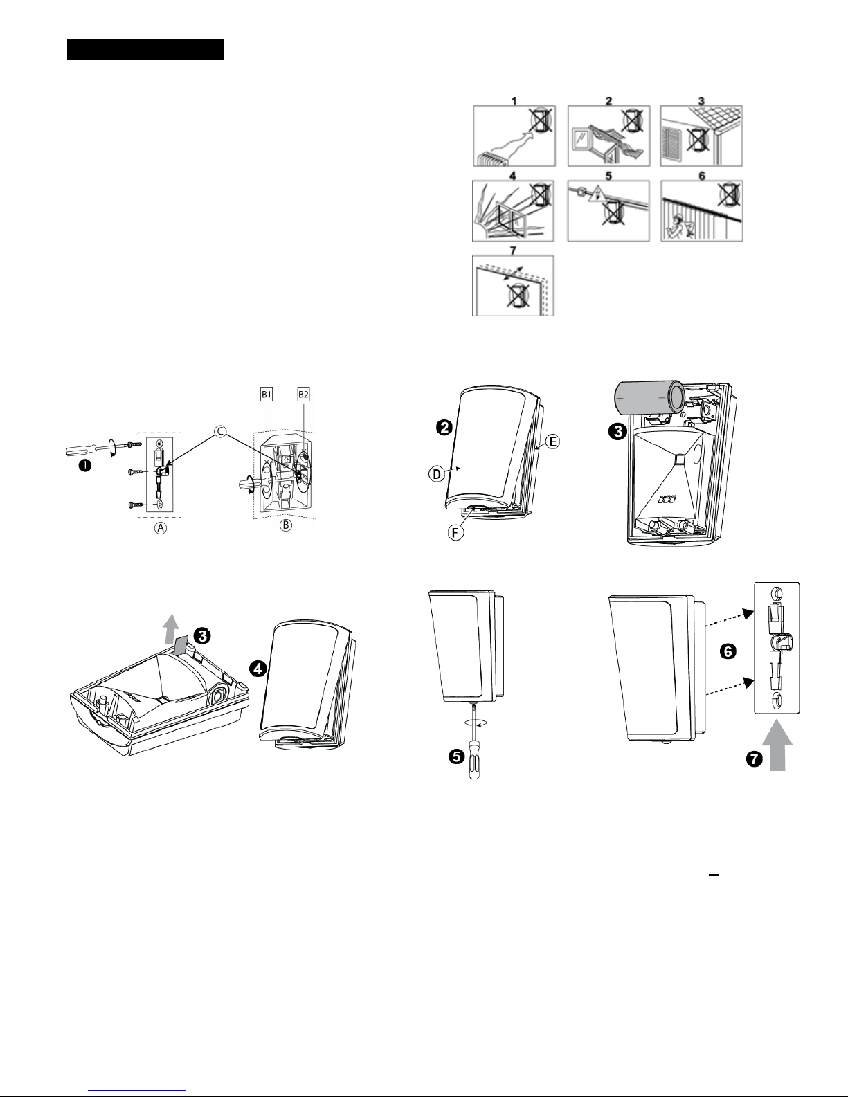
2. INSTALLATION
2.1. General Guidance
1. Keep away from heat sources.
2. Do not expose to air dr afts.
3. Do not install outdoor s.
4. Avoid direct sunshine.
5. Do not install near high-voltage electricalline.
6. Do not install behind partitions.
7. Mount on solid stable surface.
Warning! Do not obscure partiallyor completely the detector's field of
view.
Figure 3 - General Guidelines
2.2. Installation Procedure
Figure 4 - Bracket Mo unting
Figure 5 - Opening the Unit
Figure 6a - Battery Insertion
Figure 6b - Battery Activation
Figure 7 - Closin g t he Cover
Figure 8 - Securing with Screw
Figure 9 - Mounting Detector on
Bracket
1. Mount the bracket on the wall.
2. Press in the point marked "F" in the drawing and separate the cover from the base.
3. Insert the battery while observing polarity-OR- If battery is already
installed, pull the activation strip that protrudes fr om the fr ont of the detector.
4. Return the cover to the base until aclick is heard (the snap is closed).
5. Secure detector with screw.
6. Align the detector with the bracket.
7. Slide the detector upward until a clickis heard.
A. Surface mounting
B. Corner mounting, use B1 or B2
C. For backtamper
D. Cover
E. Base
F. Press in this point
Note: The detector transmits a low battery signal upon detection of low voltage. It is recommended to waitabout 1 minute after battery r emoval, before
inserting the new battery.
MP-802 K9-85 shall be installed in accordance with the Standard for Installation and Classification of Burglar and Holdup Alarm Systems, UL 681.
Caut ion! Riskof explosion if battery is replaced by an incorrect type. Dispose of used battery according to the manufacturer's instructions.
D-306133 MP-802 K9-85 PG2 Installation Instructions 2
Page 3
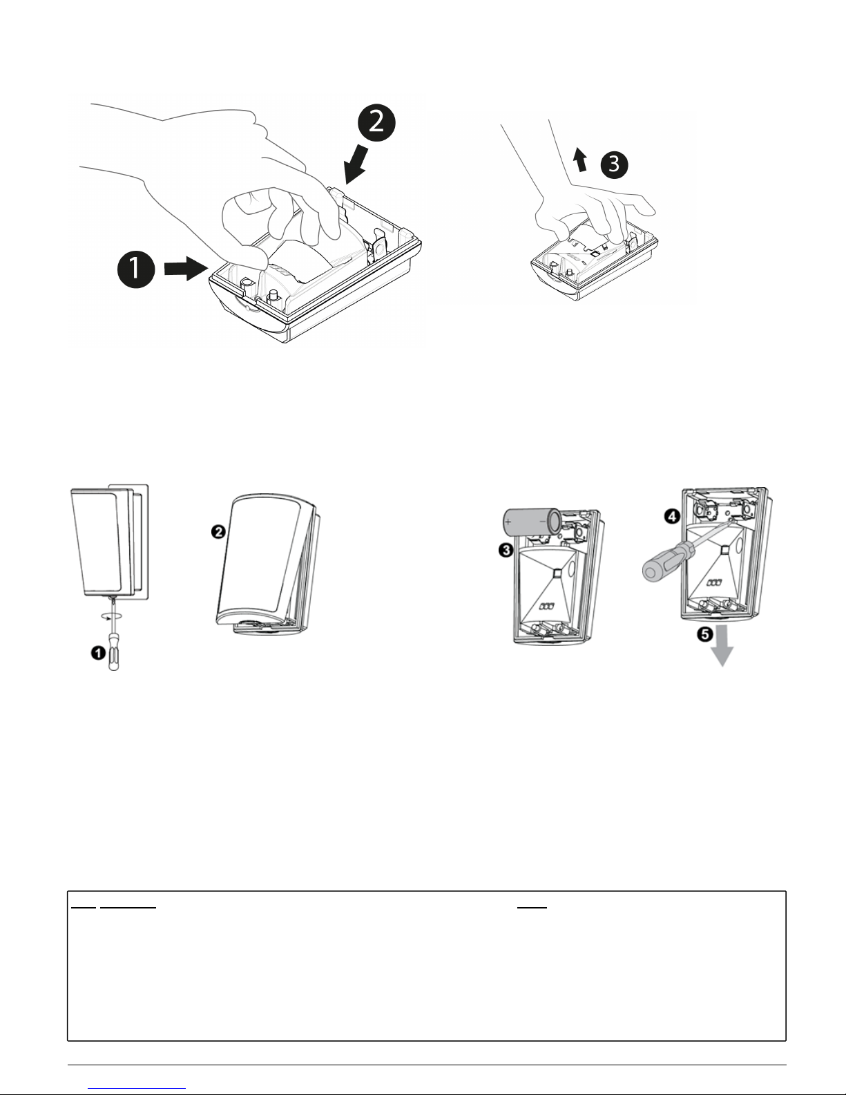
2.3. Removing the Pet Mask
Remove the plastic (pet mask) if you do not require pet immunity.
Figure 10 - Removing the Pet Mask
1. Place your thumb atthe base of the Pet Mask.
2. Place your fingers at the top of the Pet Mask.
3. Lift the Pet Mask to remove.
2.4. Disassembly from Bracket
Figure 11 - Disassembly from Bracket
1. Release screw.
2. Separate the cover from the base.
3. Remove battery.
4. Press on the stopper snap to release the base from the bracket.
5. Slide the base downward to remove.
2.5. Enrollment
Refer to the PowerMaster panel's Installer Guide and follow the procedure under the "02:ZONES/DEVICES" option of the Installer Menu. A general
description of the procedure isprovided in the following flow chart.
For UL/ULC listed installations use only in conjunction with UL/ULC listed conrol panels: PowerMaster-10 and Power Master-30 G2.
Step Procedure Menu
1 Enter the installer menu and select “02:ZONES/DEVICES” 02:ZONES/DEVICES
2 Select “ADD NEW DEVICES” Option – See Note [1]
ADD NEW DEVICES
↓
MODIFY DEVICES
3
Select “ADD NEW DEVICES” Option – See Note [1] Enroll the device or enter the
device ID
ENROLL NOW or ENTR ID:XXX-XXXX
D-306133 MP-802 K9-85 PG2 Installation Instructions 3
Page 4

4 Select the desired Zone Number
Z14:Motion Sens (with panels PowerG V19.2 and
lower)
ID No. 120-XXXX (with panels PowerG V19.2 and
lower)
Z14:S.Motion (with panels PowerG V19.3 and higher)
ID No. 126-XXXX (with panels PowerG V19.3 and
higher)
5 Configure Location, Zone Type & Chime Par ameters
Z14:LOCATION
Z14:ZONE TYPE
Z14:SET CHIME
Z14 :DEV SETTINGS
6 Configure the detector See Note 2
Notes:
[1] If the detector is already enrolled, you can configure the detector parameters via the modify devices option – see step 2.
[2] Select the “Device Settings” option and refer to section3 to configure the detector parameters.
3. Temperature Display
For instructionson displaying the temperature of zones on the control panel as measured byMP-802 PG2 detectors, refer to the PowerMaster Installer
Guide, section 4.2 “Conducting a Periodic Test”.
4. Configuring the Detector Parameters
Enter the DEVICE SETTINGS menu and follow the configuration instructions for the MCP-802 K9-85 PG2 detector asdescribed in the following table.
Option Con fig urin g In structio ns
Alarm LED Define whether or not the alarm LED indication will be activated. Optional settings: LED ON (default) and LED OFF.
Event
Counter
Define whether an alarm willbe activated upon continued motion (low sensitivity) or upon a single alarm event ( high sensitivity).
Optional settings: LOW sensitive ( default) and HIGH sensitive.
DISARM
Activity
Define whether or not to set the activity time during disarm. Optional settings: NOT Active(default), YES – nodelay, YES + 5s delay,
YES + 15s delay, YES + 30s delay, YES + 1m delay, YES +2m delay, YES + 5m delay, YES + 10m delay, YES +20m delayand YES +
60m delay.
VERY HOT
> 35°C [
>95°F]
Define whether or not the control panel will report a "very hot" alert when the temperature rises above 35°C (95°F) for at least 10
minutes. Alert restore willoccur when the temperature drops below 34°C (93°F) for the duration of 10 minutes. Optional settings:
Disable (default) or Enable
COLD <
19°C [
<66°F]*
Define whether or not the control panel will report a "cold" alert when the temperature drops below 19°C (66°F) for at least 10
minutes. Alert restore willoccur when the temperature risesabove 20°C (68°F) for the duration of 10 minutes. Optional settings:
Disable (default) or Enable
FREEZING
< 7°C [
<45°F]*
Define whether or not the control panel will report a "freezing" alert when the temperature drops below 7°C (45°F) for at least 10
minutes. Alert restore willoccur when the temperature risesabove 8°C (48°F) for the duration of 10 minutes. Optional settings:
Disable (default) or Enable
FREEZER
> - 10°C [
<14°F]*
Define whether or not the control panel will report a "freezer" alert when the temperature rises above -10°C (14°F) for atleast 30
minutes. Alert restore willoccur when the temperature drops below -11°C (12°F) for the duration of 10 minutes. Optional settings:
Disable (default) or Enable
Note: The temper ature must pass beyond the threshold for the required duration in order to generate an alarm or restore transmission.
Note: The user can give accessto installer to r emotely enable or disable the indication led.
5. LOCAL DIAGNOSTICS TEST
Note: Run a diagnostic test at least once a year to ensure that the detector is working correctly.
1. Separate the base from the cover (see Figure 5).
2. Replace the cover to return the tamper switch to its normal (undisturbed) position, and then secure the front cover to the base with the caseclosure
screw.
3. The MP-802 K9-85 PG2 detector will enter a 2 min. stability per iod. During this time the red LED blinks.
D-306133 MP-802 K9-85 PG2 Installation Instructions 4
Page 5

4. Walk-test the coverage area – see F igure 12. Walk across the far end of the coverage pattern in both directions. T he red LED lights each time your
motion is detected followed by3 LED blinks.
The following table outlines received signalstrength indication:
LED response Reception
Green LED blinks Strong
Orange LED blinks Good
Red LED blinks Poor
No blinks No communication
Important! Instruct the user to walk test at least once a week to verify pr oper function of the detector.
Important! Reliable r eception must be assured. Therefor e, poor signalstrength is not acceptable. If you receive a poo r signal from the device, re-
locate it and re-test until a go od or strong signal strength is received (in regions requiring UL-compliant installation, only strong signal strength is
permitted).
Notes:
[1] For detailed diagnostics test instructions, refer to the control panel Installer Guide.
**This menu appears in PowerMaster V19.3 or above only. In earlier versions, this menu will appear only after completing the following procedure:
a. Upgrade the Power Master control panel to V19.3 or above.
b. Delete the MP-802 K9-85 PG2 detector from the PowerMaster control panel.
c. Enroll the detector to the PowerMaster control panel again.
6. COMPLIANCE WITH STANDARDS
The MP-802 K9-85 PG2 complies with the f ollowing standards:
Europe:EN 300220, EN 301489, EN 60950-1, EN 50130-4, EN 50131-1, EN 50131-2-2 Grade 2 Class II, EN 50130-5, EN 50131-6 Type C
UK: The MP-802 K9-85 PG2 is suitable for use in systems installed to conform to PD6662:2010 at Grade2 and environmental CLASS II. DD243 and BS8243.
The Power G peripheral devices have two-way communication functionality, providing additional benefits as described in thetechnical brochure. This functionality has not been testedto comply
with the r espective technical r equirements andshould therefore be considered outside the scopeof the product's certification.
Certified by Applica Test & Certification ASin accordance with EN 50131-2-2, EN 50131-5-3, EN 50131-6, EN 50130-4, EN 50130-5 Applica T&C has certified
only the 868 MHz variant of this product.
This device is in compliancewith Directive 2014/53/EU. The full text of the DoC isavailable at: http://www.visonic.com/download-center.
USA: FCC-CF R 47 Par t 15, UL- UL 639
Canada:IC-RSS 247, ULC – S306
Note: Onlydevices operating at 912-919 MHz are tested and listed by UL/ULC.
This device complieswith Part 15 of the FCC Rulesand with ISED license-exempt RSS standard(s). Operation is subject to the following two conditions:
(1) This device may not cause harmful interference, and (2) thisdevice must accept any interference received, including interference that may cause
undesired operation.
Le présent appareil est conforme auxCNR d'ISED applicables aux appareils radio exempts de licence. L'exploitation est autorisée aux deux conditions
suivantes : (1) l'appareil ne doit pas pr oduire de brouillage, et (2) l'utilisateur de l'appareil doit accepter tout brouillage r adioélectrique subi, même si le
brouillage est susceptibled'en compromettre le fonctionnement.
WARNING! Changes or modifications to this unit not expressly approved by the party responsible for compliance could void the user’s authority to
operate the equipment.
To comply with FCC and IC RF exposure compliancerequirements, the device should be located at a distance of at least 20 cm from allpersons during
normal operation. The antennas used for this product must not be co-located or oper ated in conjunction with any other antenna or transmitter.
Le dispositif doit être placé à une distance d'au moins20 cm àpartir de toutes les per sonnes au cours de son fonctionnement normal. Les antennes
utilisées pour ce produit ne doivent pasêtre situés ou exploitésconjointement avec une autre antenne ou transmetteur.
Note: This equipment has been tested and found to comply with the limitsfor a Class B digitaldevice, pursuant to part 15 of the FCC Rules. These limits
are designed to provide reasonable protection against har mful interference in a residentialinstallation. This equipment generates, uses and can radiate
D-306133 MP-802 K9-85 PG2 Installation Instructions 5
Page 6

radio frequency energy and, if not installed and used in accordance with the instructions,may cause harmful interference to radio communications.
However, there isno guarantee that interference will not occur in a particular installation. If thisequipment does cause harmful interference to radio or
television reception, which can be deter mined byturning the equipment off and on, the user is encouraged to try to correct the interference byone or
more of the following measures:
-Reor ient or relocate the receiving antenna.
-Increase the separation between the equipment and receiver.
-Connect the equipment into an outlet on a circuit different from that to which the receiver isconnected.
-Consult the dealer or an experienced radio/TV technician for help.
Cet équipement a été testé et jugé conforme aux limites s’appliquant à un appareil numérique de classe B, conformément à la Partie 15 des
réglementations de la FCC. Ces limitesont été élaborées pour offrir une protection raisonnable contre les interferences nuisibles dans une installation
résidentille.
Cet équipement génère, utilize et peut émettre de l’énergie de fréquence radio et, s’il n’est pasinstallé et utilize conformément aux instructions du
fabricant, peut provoquer des interférences dangereuses pour les communications radio. T outefois, rien ne garantit l’absence d’interférences dans une
installation particuliére. Sicet équipement provoque des interférences nuisibles au niveau de la réceptionradio ou television, ce quipeut étre determine
par la mise hors, puis sous tension de l’équipment, vous étes invite à essayer de corriger les interferences en pregnant les mesures suivantes:
• Réorientez ou déplaces l’antenne réceptrice.
• Augmentez la distance qui sépare l’équipement et le récepteur.
• Branchezl’équipement à une prise d’un circuitdifferent de celuiauquel est branché le récepteur.
• Consultezle revendeur ou un technician radio/television expérimenté pour obtenir de l’aide
7. Special Comments
Even the most sophisticated detectors can sometimes be defeated or may fail to warn due to: DC power failure /improper connection, malicious
masking of the lens, tampering with the optical system, decreased sensitivity in ambient temperatures close to that of the human bodyand unexpected
failure of a component part.
The above list includes the most common reasons for failure to detect intrusion, but isby no meanscomprehensive. It is therefore recommended that
the detector and the entire alarm system be checked weekly, to ensure proper performance.
An alarm system should not be regarded as a substitute for insurance. Home and property owners or renters should be prudent enough to continue
insuring their lives and property, even though theyare protected byan alarm system.
W.E.E.E. Product Recycling Declaration
For information regarding the recycling of this product you must contact the company from which you originally purchasedi t. If youare discarding this product and not returning it for repair then you
must ensure that it is returned as identified by your supplier. This product is not to be thrown away with everyday waste.
Directive 2002/96/EC Waste Electrical and Electronic Equipment.
D-306133 MP-802 K9-85 PG2 Installation Instructions 6
Page 7

8. SPECIFICATIONS
GENERAL
Detector Type Dual element low-noise pyroelectric sensor
OPTICAL
Lens Data
Fresnel and cylinder type lens with optical attenuation
(PET mask) in the lower pattern part of the lens.
Number of beams/curtains: 27 Fresnel far (54 sensitivity
“beams”) , 18 Cylinder mid, 10 Cylinder close.
Figure 12 – Coverage
Pattern Walk Test
Max. coverage 12 x12 m (39 x 39 ft) / 90°
Pet Immunity Up to 38 kg (85 lb)
ELECTRICAL
Power Supp ly Type C.
Internal Battery 3V Lithium battery, type CR-123A. For UL installations,use Panasonic and GPonly
Nominal Batt ery
Capacity
1450 mAh
Batt ery Lif e (t ypical use) Minimum 1 year. For typical use, 6 to 8 years ( not verified byUL).
Low Battery Threshold 2.4 V
Note:
Inabilityto connect with wireless network, or wireless link quality no higher than 20% maysignificantlyreduce the expected
battery life
Batt ery Power Test
Performed immediately upon battery insertion and periodicallyafter every several hours.
The power supplyis type C in accordance with EN 50131-6 Documentation – Clause 6.
Current Co nsumption 10μA average quiescent , maximum 40mA (during transmission)
FUNCTIONALIT Y
True Motion Event
Verification
2 remote selections at panel – LOW, HIGH
Alarm Period 2 seconds
LED Switch LED Enable (red LED lights for 2 sec. upon alarm detection)
WIRELESS
Frequency
Europe and rest of world: 433-434 MHz, 868-869 MHz USA: 912-919 MHz
Note: Onlydevices in frequency band 915 MHz are UL/ULC listed
Max Tx Power <10 dBm (433-434), <14dBm (868-869)
Communication Protoco l Power G
Supervision Signaling at 4-min. intervals
Tamper Alert Reported when atamper event occurs and in any subsequent message, until the tamper switch is restored
MOUNTING
Height
1.8-2.4 m (6 - 8ft.). For pet rejection, the optimal height is2.1 m (7 ft.)
At 2.4m (7.87 ft.) height installation, remove pet mask as pet immunity is not supported.
Installatio n Options Surface or corner
ENVIRONMENTAL
RF Immunity 20 V/m up to 1000 MHz, 10 V/m up to 2700 MHz
Operating Temperatu res -10°C to 50°C (14°F to 122°F). Note: UL verified operation range 0°C to49°C only.
D-306133 MP-802 K9-85 PG2 Installation Instructions 7
Page 8

Storage Temperatures -20°C to 60°C (-4°F to 140°F)
Humidity
Average relative humidityof up to approximately 75% non-condescending. For 30 daysper year the relative humidity may
vary between 85% and 95% non-condescending.
For UL installations: 5 % to 93 % with no condensation
PHYSICAL For indoor useonly.
Size (H x W x D) 83 x 61 x 42 mm (3.27 x2.4 x1.66")
Weight (with battery) 90 g (3.17 oz)
Colo r White
PATENT S U.S. Patents5,693,943 ● 6,211,522
WARRANTY
Visonic Limited (the “M anufacturer") warrants this produ ct only (th e "Product") t o the original purchaser on ly (the
“Purchaser”)a gainstde fective workman shipa nd mate rialsunde rnorma luse of the Product for a period oftw elve (12)
mon thsfrom the date of shipment byt heM anufacturer.
This Warranty isa bsolutely conditional up on th e Product h aving be en properly installed, m aintained and opera ted
unde r conditions of n ormal u se in accordance with th e Manu facturers recom men ded installation a nd operat ion
instructions. Products which ha ve becom ede fective for anyot her reason, accordingto the Man ufacturers discretion,
such as imprope r installation, fa ilure to follow recommen ded installation a nd operat ional instructions, neglect, willful
dam age, misuse or vand alism, a ccidenta l dam age, alteration or tam pering, o r repair by anyone othe r than the
man ufacturer, areno tcovered byt hisWarranty.
The Manu facturer does no t represent tha t this Product m ay not b e comprom ised and/ or circumvent ed o r that the
Product willprevent any dea tha nd/o rpersonal injuryan d/ord amage to property resulting from burglary, robbery, fire
or oth erwise, or that the Produ ct willin all cases p rovide ade quat e warning or prot ection. The Product, p roperly
installed and m aintained ,on ly reducesth e riskof such events withou twa rning and it isno t a guaran tee o r insurance
that such events willnot occur.
THIS WAR RANTY IS EXCLUSIVE AND EXPRESSLYI N LIEU OF ALL OTHER WARRANTIES, OBLIGATIONS
OR LIABILITIES, WHETHER WRITTEN, ORAL, EXPRESS OR IM PLIED, IN CLUDIN G A NY WAR RANTY OF
MERCHAN TABILITY OR FITNESS FOR A PARTICULA R PURPOSE, OR OTHERWISE. IN NO CASE SHALL
THE M ANUFAC TURER BE LIABLE TO ANYONE FOR AN Y CONSEQUENTIAL OR INCID ENTAL D AMAGES
FOR BREACH OF THIS WARRAN TY OR A NY OTHER WARRA NTIES WHATSOEVER, A S AFORESAID.
THE M ANUF A CTU RER SHAL L IN NO E VENT BE LIAB LE F OR A N Y SPECIA L, IN DIRE CT, I NCID ENTA L,
CONSEQUENTIA L OR PUNITI VE D AMAGES O R FOR LOSS, DAMAGE, OR EXPENSE, INCLU DING LOSS O F
USE, PROFITS, R EVENUE, OR GOODWILL, DIR ECTLY OR IND IRECTLY AR ISING FROM PURCHA SER’S USE
OR INABI LITY TO USE TH E PROD UCT, OR FOR LOSSOR DESTRUCTI ON OF OTHER PROPERTY OR FR OM
ANY OTHER C AUSE, EVEN I F MA NUF A CTU RER HAS BEEN A DVISED OF T HE POSSIBI L ITY OF SUC H
DAMA GE.
THE M A NUF A CT URE R S HAL L H A VE N O L IAB ILI TY FOR A N Y D EATH , PERSON AL AND/ OR BOD IL Y
INJUR Y AN D/OR DAM AGE TO PROPERTY OR OTHER LOSS WHETHER DIR ECT, IN DIREC T, INC IDENTA L,
CONSEQUENTIAL OR OTHERWISE, BASED ON A CLAIM THAT THE PRODUCT FAILED TO FUNCTI ON.
Howe ver, ifth e Manu factureris held liable, whet her directlyor indirectly,for a nylossor da mage arising und erthis limited
warranty, THE MA NUFACTUR ER’S M AXIMUM LIABILITY (IF ANY) SHALL NOT IN A NY C ASE EXCEED THE
PURCHASE PRICE OF THE PRODUCT, which shall be fixed as liquidated dam agesa nd not asa pena lty,a ndsha ll be
the complete and exclusiverem edyag ainst theM anufactu rer.
When accepting the delivery of the Produ ct, the Purchaser agrees to the said conditions of sale an d warranty and he
recognizesh aving been informed of.
Some jurisdictionsd ono tallow the exclusion orlimitation ofincidenta lorcon seque ntiald amages, sot hese limitations may
not apply unde rcertain circumstances.
The M anufacturer shall be un der no liability whatsoever arising o ut of the corruption an d/or malfunctioning o f an y
telecomm unication ore lectronicequ ipmen tor anyp rogram s.
The M anufacturers ob ligations un der this Warranty are limited solely to repair and /or replace a t the Ma nufacturer’s
discretion an y Product or pa rt there of th at may prove d efective. Any repair and /or replacement shall not extend the
original Warranty p eriod. The Ma nufacturer shall not be re sponsible for dismantling an d/or reinstallation costs. To
exercise thisWarran ty the Product mu st be ret urned to th e Manu facturer freight pre-pa id and insured. All freight a nd
insurance costsare the responsibilityof the Purchaseran dare not included in thisWarrant y.
Thiswarran tyshallnot be mod ified, variedo rextend ed,a nd the Manu facturerd oesno taut horize any person toact on its
beha lf int he modification, variation orexten sion of thiswarrant y.Th iswarran tysha llapp lyto the Product only. Allprod ucts,
accessorieso rattachm ents of others used incon junction with the Product, including batteries, shallbe covered solely by
their own warranty, if a ny. The Man ufacturer shall not be liable for any da mage o r loss whatsoever, wh ether directly,
indirectly, incident ally, conseque ntially or othe rwise, caused by the malfunction o f th e Product due to prod ucts,
accessories,o ratta chmen tsof others, including batte ries,u sed in conjunction witht he Products. ThisWarranty isexclusive
to the original Purchaseran disn ota ssignab le.
ThisWarranty isin a ddition to and doe sn ota ffect your legalrights. Any provision inth is warranty which iscontrary to the
Law inth estate or countrywe re the Product issupp liedsha llnot apply.
Warning: The user must follow the Manu facturer’sinstallation and operationa linstructions including te sting the Product
and its whole system at least once a week and to take a llnecessary precautions for his/her safety an dthe prote ction of
his/her property.
Email: info@visonic.com
Internet: www.visonic.com
© VISONIC LTD. 2017 MP-802 K9-85 PG2 D-306133 (Rev. 2 05/17)
D-306133 MP-802 K9-85 PG2 Installation Instructions 8
 Loading...