

Page 1

VisionNet
Network DVR
- SW-80
User Manual
VisionNet Technology
Page 2

TABLE OF CONTENTS
SW-80 UM
................................................................................................................................................1
INTRODUCTION ..................................................................................................................................4
VERVIEW
O
TANDARD FEATURES
S
PTIONAL FEATURES
O
RCHIVE BACKUP SYSTEM MODE
A
UDIO RECORDING OPTION
A
.............................................................................................................................................4
...........................................................................................................................4
.............................................................................................................................4
.........................................................................................................6
...................................................................................................................6
FRONT PANEL......................................................................................................................................7
REAR PANEL.........................................................................................................................................8
AMERA CONFIGURATION
C
.....................................................................................................................8
STARTING THE SYSTEM ................................................................................................................9
URN ON THE POWER
T
OGON
...................................................................................................................................................9
L
HE MAIN SCREEN
T
.............................................................................................................................9
.................................................................................................................................9
DISPLAY (THE MULTIPLEXER FUNCTION) ..............................................................................10
ISPLAY CONTROL PANEL
D
CREEN MODE
1-S
CREEN MODE
4-S
ULTI-SCREEN MODE
M
CREEN MODE
8-S
CREEN MODE
16-S
APID ZOOM
R
ULL SCREEN DISPLAY
F
EQUENCE
S
..................................................................................................................................11
..................................................................................................................................11
..................................................................................................................................13
........................................................................................................................................14
...........................................................................................................................................14
....................................................................................................................10
.........................................................................................................................13
................................................................................................................................14
.........................................................................................................................14
REMOTE ONLINE VIEWING AND PLAYBACK RECORDED VIDEO....................................14
HE INTELLIGENT REMOTE PLAYER
T
PICO S
ERVER BUTTON
.......................................................................................................................14
....................................................................................................14
RECORDING........................................................................................................................................15
TORAGE DRIVE
S
ECORDING MODES
R
ULTIPLE CAMERA RECORDING
M
HE RECORDER CONTROL PANEL
T
NSTANT RECORDING
I
LARM RECORDING
A
ALARM RECORDING
PRE-
CHEDULED RECORDING
S
...................................................................................................................................15
.............................................................................................................................15
..........................................................................................................15
.........................................................................................................15
...........................................................................................................................16
.............................................................................................................................17
......................................................................................................................17
......................................................................................................................18
PLAYBACK..........................................................................................................................................19
LAYBACK THE VIDEO
P
ELECT DRIVE
S
HE VIDEO PLAYER
T
IST FILE RECORD
L
IDEO PLAYBACK CONTROLS
V
.....................................................................................................................................19
.........................................................................................................................19
..............................................................................................................................20
...............................................................................................................................20
..............................................................................................................21
Page 1 of 73
Page 3

LAYBACK CAMERA CONTROL
P
BSOLUTE DATE/TIME AND LENGTH DISPLAY
A
LAYBACK SPEED CONTROL
P
EWIND AND REPLAY
R
RAME MODE FOR PRINT AND SAVE A FRAME
F
ETURN TO VIDEO MODE
R
HE VIDEO SEARCH ENGINE
T
LAYBACK THE CURRENT FILE
P
PEN THE VIDEO FILES AND PLAYBACK CONTINUOUSLY
O
EARCH THE VIDEO INTERACTIVELY
S
..........................................................................................................................21
.............................................................................................................21
......................................................................................21
................................................................................................................21
......................................................................................21
.....................................................................................................................21
* ...............................................................................................................22
.............................................................................................................22
.....................................................................22
....................................................................................................22
MOTION DETECTION ......................................................................................................................23
OTION DETECTION
M
ET UP THE MOTION DETECTION
S
ET DETECTION AREA
S
NDICATE THE DETECTION AREA
I
ET SENSITIVITY FOR MOTION DETECTION
S
ETECTION INTERVAL
D
ECORDING TIME EXTENSION
R
NABLE THE MOTION DETECTION FUNCTION
E
IPS
T
.....................................................................................................................................................25
............................................................................................................................23
..........................................................................................................23
..........................................................................................................................24
..........................................................................................................24
...........................................................................................24
.........................................................................................................................24
..............................................................................................................24
.......................................................................................24
PAN-TILT ZOOM CONTROL...........................................................................................................26
TILT ZOOM
PAN-
RIVER MODE SETTING
D
ORT SETTING
P
AMERA SELECTION
C
ONITOR SELECTION
M
PEED CONTROL
S
TILT ZOOM CONTROL
PAN-
RE-POSITION
P
...................................................................................................................................26
.......................................................................................................................26
.....................................................................................................................................27
............................................................................................................................27
..........................................................................................................................27
..................................................................................................................................27
...................................................................................................................27
......................................................................................................................................27
UTILITY FUNCTIONS .......................................................................................................................28
CCESS TO UTILITY FUNCTIONS
A
E-ACTIVATE THE DISABLED HOUSEKEEPING FUNCTIONS
R
..........................................................................................................28
..................................................................28
CAMERA CONFIGURATION...........................................................................................................29
AMERA TITLE ASSIGNMENT
C
AXIMUM NO. OF CAMERA IMPOSED BY SOFTWARE
M
HECK THE ACTIVE CONNECTED CAMERAS
C
PPLY THE CAMERA TITLE
A
...............................................................................................................29
............................................................................29
.........................................................................................29
...................................................................................................................29
RECORDER SETTING.......................................................................................................................30
HE RECORDING PARAMETERS
T
RAME RATE
F
HE START AND END TIMES FOR SCHEDULED RECORDING
T
NSTANT RECORDING
I
LARM RECORDING
A
ALARM RECORDING
PRE-
CHEDULED WEEKDAY RECORDING
S
CHEDULED WEEKEND RECORDING
S
XAMPLE
E
XAMPLE
E
UDIO RECORDING
A
........................................................................................................................................30
...........................................................................................................................31
.............................................................................................................................32
1 ..........................................................................................................................................35
2 ..........................................................................................................................................35
..............................................................................................................................35
............................................................................................................30
....................................................................30
......................................................................................................................32
.....................................................................................................33
.....................................................................................................34
OPTION SETTING..............................................................................................................................36
ISPLAY SEQUENCING
D
MAGE RESOLUTION FOR ALL RECORDING
I
ECORDING MODE SELECTION
R
TTACH AUDIO TO CAMERA
A
RIVE CAPACITY
D
.........................................................................................................................36
............................................................................................37
.............................................................................................................37
...............................................................................................................37
.................................................................................................................................37
Page 2 of 73
Page 4

ACKUP FUNCTION
B
ORMAL MODE
N
RCHIVE MODE
A
WAP DRIVE
S
INSERTION OF REMOVABLE DRIVE
RE-
YSTEM OPERATION DATA
S
..............................................................................................................................38
...................................................................................................................................38
...................................................................................................................................38
........................................................................................................................................39
.................................................................................................39
...................................................................................................................40
HOUSEKEEPING ................................................................................................................................41
ACKUP
B
R
H
S
...............................................................................................................................................41
EMOVE VIDEO FILES
OUSEKEEPING TOOLS
YSTEM INFORMATION
..........................................................................................................................42
.........................................................................................................................43
........................................................................................................................44
TOO MANY FILES WARNING.........................................................................................................45
OO MANY FILES WARNING MESSAGE
T
NVOKE THE MESSAGE BOX
I
EMOVE THE MESSAGE BOX
R
ETUP AND THE DEFAULT VALUES
S
..................................................................................................................45
................................................................................................................45
..................................................................................................45
.......................................................................................................46
WORKING AT LOGOFF ...................................................................................................................47
OG OFF
L
R
...............................................................................................................................................47
ECORDING DURING LOG OFF
..............................................................................................................47
SHUT DOWN THE UNIT ...................................................................................................................47
XIT
E
.....................................................................................................................................................47
SYSTEM MAINTENANCE ................................................................................................................48
CHEDULE BACKUP AND REMOVE THE VIDEO FILE
S
OMPACT DATABASE SYSTEM
C
Appendix I
Appendix II
Appendix III
Appendix IV
Appendix V
Appendix VI
Appendix VII
Warranty Guide
Configuration at Control Panel
Video Transmission Server Functions
Working at Log Off Guide
Alert Modules
Remote Online Viewing and Playback
Internet Connection Guide
Find out Your IP Address
..........................................................................................................
.............................................................................................................48
...............................................................................48
..........................................................................................................
..........................................................................................................
..........................................................................................................
..........................................................................................................
..........................................................................................................
..........................................................................................................
..........................................................................................................
..........................................................................................................
52
58
60
61
65
68
71
73
Page 3 of 72
Page 5

VisionNet SW-80 User Menu
Introduction
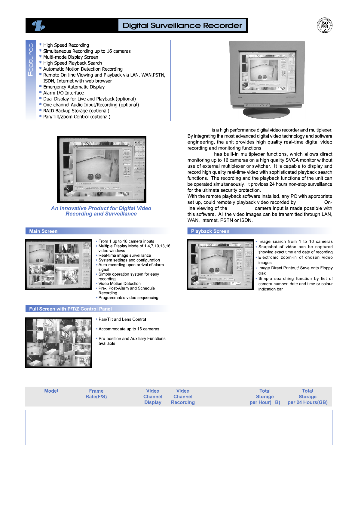
Overview
Standard Features
The SW-80 Series of Network Digital Surveillance Recorder has inherently been
designed with flexibility of different video camera inputs and display different
camera images in real time. Notwithstanding the different inputs and display, all
models will have the same features which are kept as uniform throughout the
series.
!
Digital multi-channel video recorder and multiplexer
!
Support up to 16 camera inputs with multi display modes
!
Supports both PAL and NTSC standards
!
Easy to use graphic user interface
!
State of the art real-time display and recording under optimum condition of
up to 4 channels
!
Support full resolution video (640x480 PAL, 640x480 NTSC)
!
Real-time digital video compression
!
Simultaneous playback and recording
!
Playback with sophisticated search functions
!
Alarm triggered recording
!
Alarm I/O interface
!
Pre-alarm recording
!
Programmable timer for recording
!
Motion detection recording
!
Easy to expand by software upgrade and system integration
!
Multilingual Capability
!
Intelligent remote player with telephone dial up and LAN connectivity to
access on-line and recorder videos
Optional Features
!
Video displays on SVGA monitor and support a secondary display unit
!
Audio Recording attachable to selected video input
!
Pan/Tilt/Zoom Control (optionally selected Codec)
!
Fast Video Compression/decompression (optionally selected Codec)
!
Tamper protection for video recording
Page 4 of 72
Page 6
SW-80
SW-80
SW-80
SW-80
SW-80
Approximate Recording Capacity
SW-80 Series
* 1024MB=1GB
25
12.5
8
4
1
M
1
1
1
1
1
1
1
1
1
1
275
157.2
109.8
58.2
16.62
6.6
3.8
2.64
1.4
0.39
Page 7

VisionNet SW-80 User Menu
Archive Backup
System Mode
Considering the total process ( record-optional playback-backup-optional restoreerase obsolete video-recycle storage media for record) of recording of the videos
for Surveillance purpose, we can come up with two different backup system
modes:
Normal Mode – The SW-80 Digital Surveillance Recorder will record all new
video into the Fixed Hard Drive (s). As required, the operator of
SW-80 can
the backup the recorded video to an Removable
IDE drive via the Housekeeping function from the Utility Menu
The raw copy of video can optionally be deleted during the
backup process
Archive Mode-
The backup system mode of SW-80 Network Digital Surveillance Recorder should
be selected at the very beginning of overall system operation. The normal backup
mode is set by default. To switched to the Archive mode, please refer to the Backup
Function of the Options Setting Menu. You will need to have two removable IDE
drives configured in the SW-80 Digital Surveillance Recorder to support this mode
of system operation. The SW-80 application needs to be closed and restart to apply
the mode switching from each other.
The SW-80 Network Digital Surveillance Recorder will record all new
video into one of the assigned Removable IDE drive. When it is
about full, it can be removed from the recorder (system control
or physically) for additional archiving to DAT or other backup
media. The Digital Surveillance Recorder will
maintain continuous recording to an alternate removable drive
during the archiving operation. When the videos inside a
Removable drive is obsolete, they can be erased immediately
before video recording is resumed on this drive.
SW-80
Audio Recording Option
recording function can be enabled and have the recording attached to one of the
Audio
active camera. To setup audio recording, please refer to the Attaching audio to
camera of the Option Setting Menu.
Before you can activate this function, you will need to have a Sound (Capture)
board installed and properly configured to the SW-80 Network Digital Surveillance
Recorder, as follows:
Click Start-> Programs-> Accessory -> Entertainment
Click Properties from the Options Menu.
Select the Playback check: Make sure the Microphone option is selected
from the “Show all volume control” list box. Click apply and OK, then make
sure the Microphone is Muted at Playback.
Repeat the same steps for Recording, only for this time, the Microphone (or
any other input port you may choose as an input feed to the sound board as
the recording source) is selected in this case.
You will need to adjust the volume of input and output by using the sound
recorder which is built in with the Operating System.
-> Volume Control
Page 6 of 72
Page 8
VisionNet SW-80 User Menu
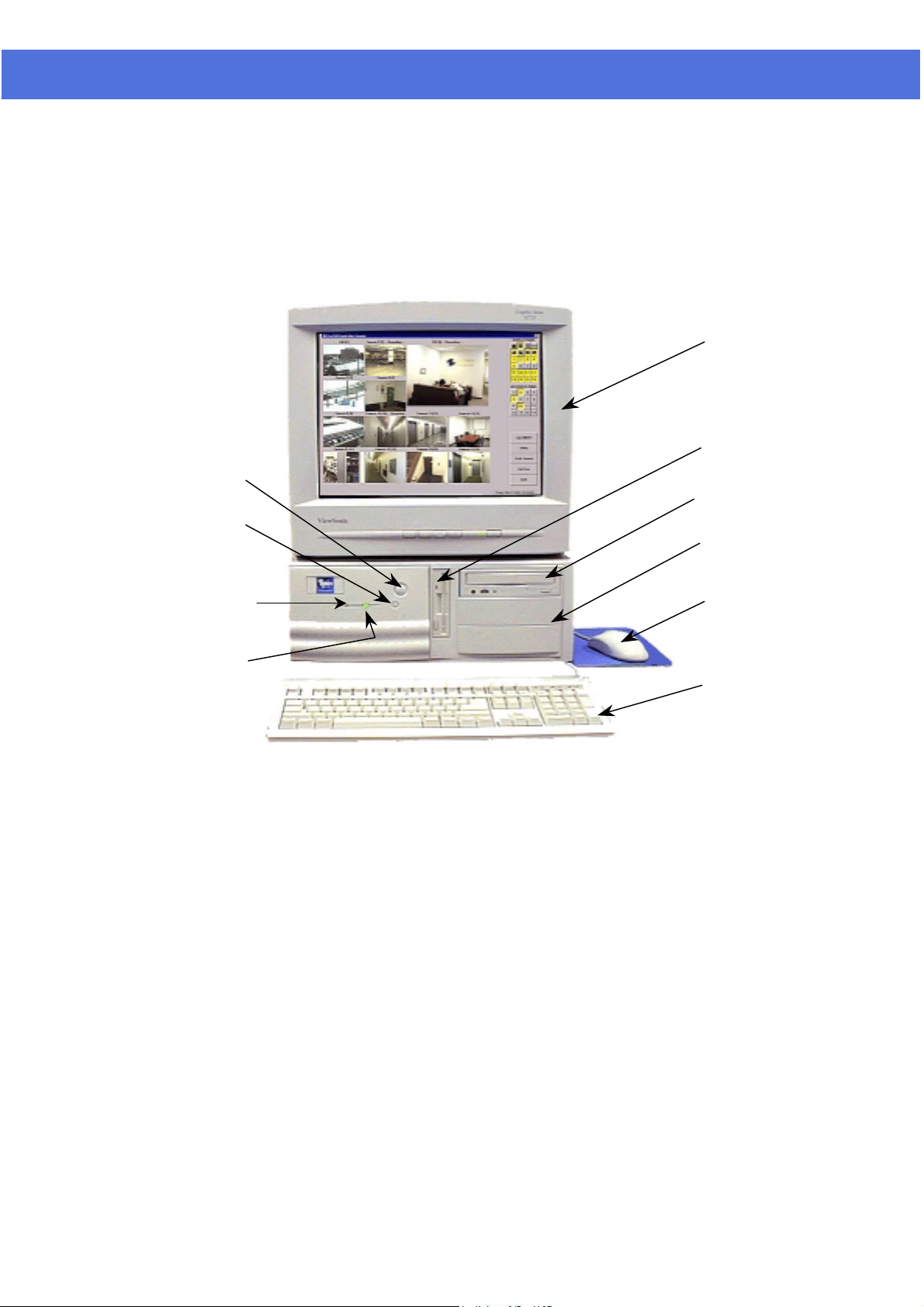
TYPICAL SYSTEM
SVGA monitor
(Optional)
Power
switch
Reset
Switch
Hard drive
indicator
Power
indicator
Floppy drive
CD ROM drive
(Optional)
PICO Unit
Mouse
Keyboard
Page 7 of 72
Page 9
VisionNet SW-80 User Menu
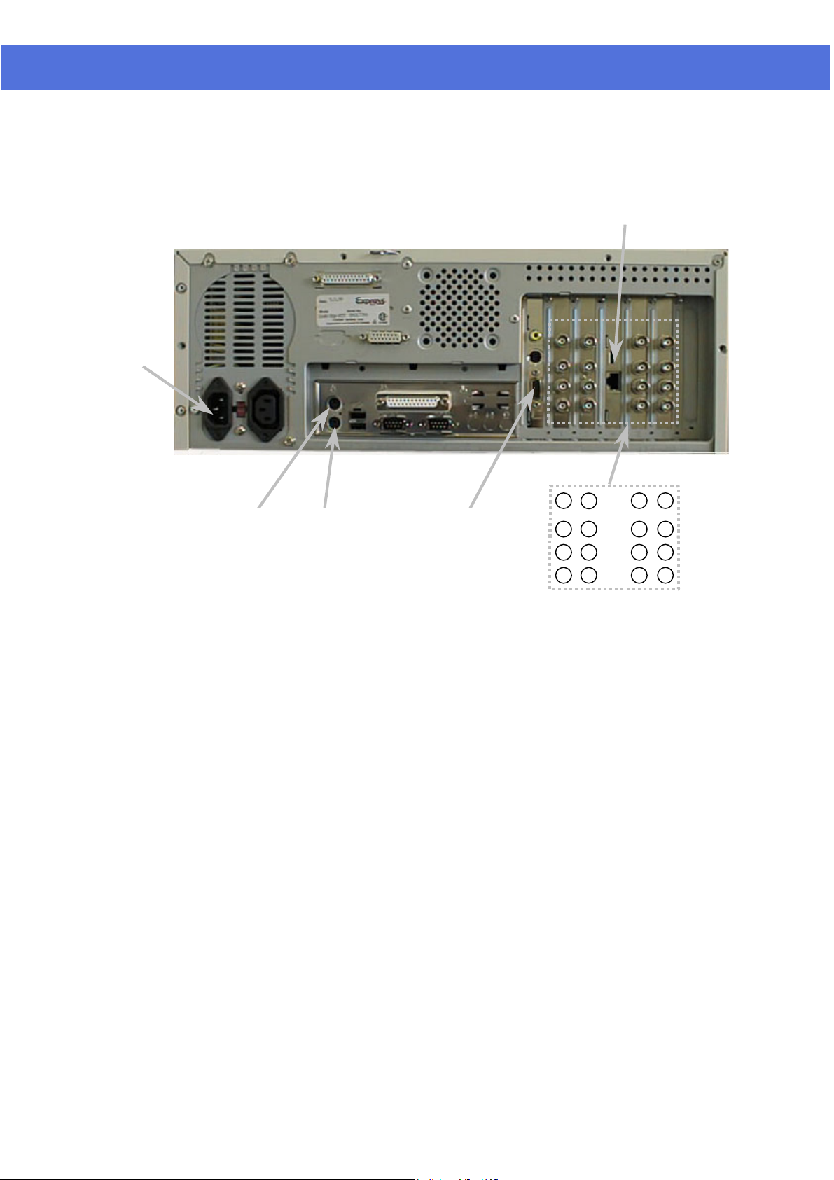
REAR PANEL
Power
LAN card
(Optional)
Camera inputs*
Mouse Keyboard
SVGA
monitor
*The number of Camera Inputs differ from different models.
*Note:
Camera
Configuration
Camera configuration includes camera connection and the camera title
assignment.
The camera should be connected to the “Camera inputs” properly prior to do the
camera configuration.
Assign camera title inside the “Camera Title” message box within the “Utility”
menu. Go to “Utility Function” chapter for detail of camera title assignment.
Tip:
Make sure that the “Active” box is unchecked for the nonconnected camera(s), in order to perform the optimum video
quality.
9
5
10
6
11
7
12
8
13
1
14
2
15
3
16
4
TEC00-014 Pico2000 User Manual (Rev. 3.0) Page 8 of 51
Page 10
VisionNet SW-80 User Menu
STARTING SW-80 SYSTEM
Turn on the power
Logon
Make sure that the line voltage selector in the rear panel is selected correctly.
Press the “POWER” switch in the front panel of the SW-80 to power up the
unit.
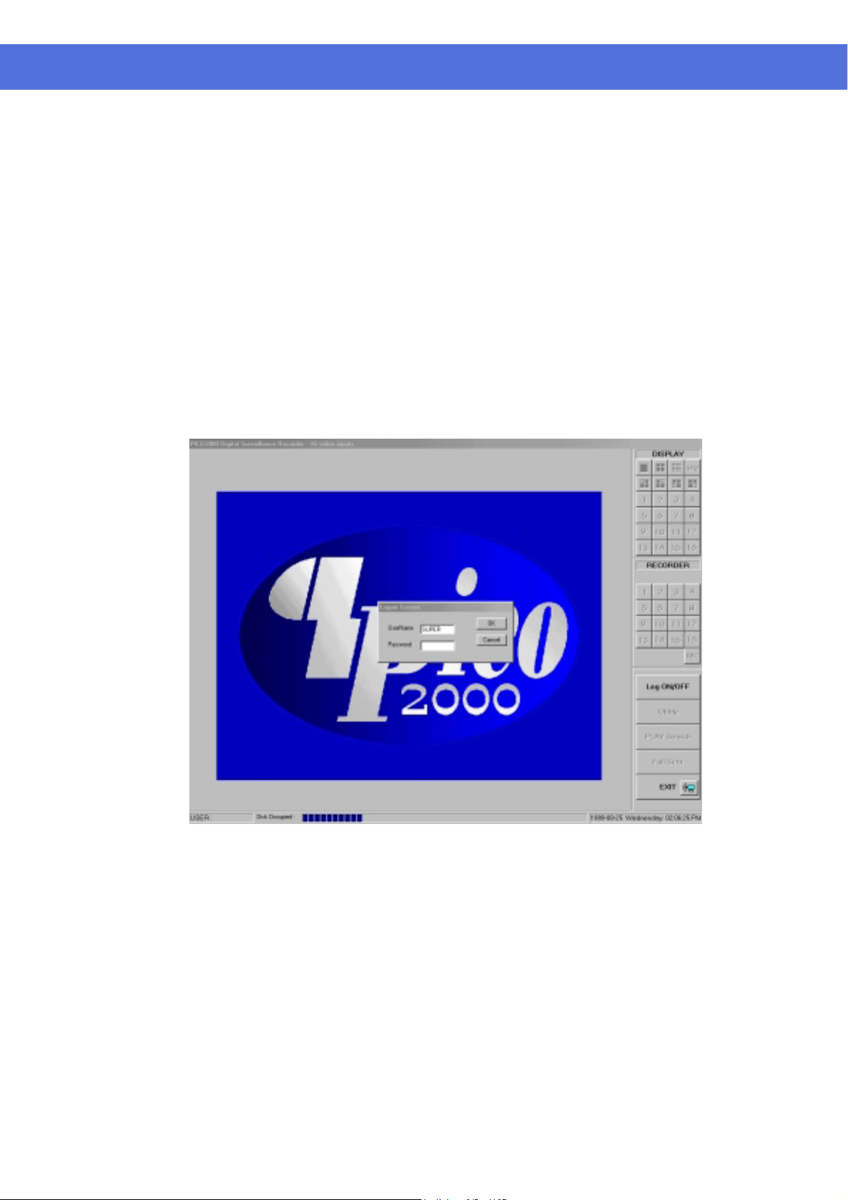
After the system start-up process, the Program logo and the main screen
appear as shown in Figure 1.
Click the “Too Many Files Warning” message box “X” icon to close the message
box.
Click the Log ON/OFF button. A Logon Screen dialog box will pop up for input.
NULL
SUPER
”, the Utility button will be disabled to
Two default usernames are available: “
The factory default password is
When you logon as “
logon password (to be discussed in more detail later on page 37).
However, if you logon as “
prevent the password and some other system and recording settings from being
modified by the operator.
SUPER
OPERATOR
”, you can click on the Utility button to change the
” and “
OPERATOR
”.
Figure 1
The main screen
TEC Page 9 of 72
Two control panels and various common control buttons are displayed on the
right hand side of the main screen.
The username is shown on the lower left-hand corner.
A progress bar located at the bottom of the screen shows the amount of storage
occupied and available for video recording. The color of the status bar will
gradually change from BLUE – when it is empty to RED – when it is full.
The current time/date is shown on the lower right hand corner.
Page 11

VisionNet SW-80 User Menu
DISPLAY (THE MULTIPLEXER FUNCTION)
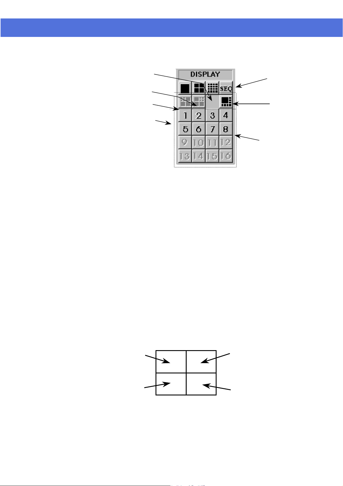
Display control panel
Display Panel
16-Screen mode button
4-Screen mode button
1-Screen mode button
Multi-Screen mode buttons
SW-80 uses
control. A “DISPLAY” panel is implemented on the upper right hand corner of
the main screen so that the user can interact with the unit more easily.
The “DISPLAY” panel consists of “display mode” buttons, “camera” buttons and
a “sequence” button respectively
All of the push buttons have their individual built-in indicator lights. Once the
button is pressed, it toggles on and off with the indicator light on and off to
indicate its status correspondingly.
a unique Graphical User Interface (GUI) design for display
Tip:
You are able to know which camera(s) is/are being displayed by the
“DISPLAY” panel indicator lights, and you can press the buttons on
the “DISPLAY” panel to enter your display input right away.
Sequence button
Camera buttons
Camera button pressed
down to start display.
Yellow light indicator
represent the camera is
displaying.
Figure 2-1
Tip:
No camera button can be selected prior to the mode selection. User
should click on one of the display mode button first.
Page 10 of 72
Page 12
VisionNet SW-80 User Menu
16-Screen mode button
4-Screen mode button
1-Screen mode button
Multi-Screen mode buttons
Figure 2-2
Tip:
No camera button can be selected prior to the mode selection. User
should click on one of the display mode button first.
Sequence button
8 split Display Mode,
With 1 Large, Higher
Refresh Rate* plus 7 small
Camera buttons
1-Screen mode
4-Screen mode
Click the 1-Screen mode button to select this mode.
Only one camera can be selected for display.
Click the camera button to select camera to display in this mode.
The down button will light up in yellow.
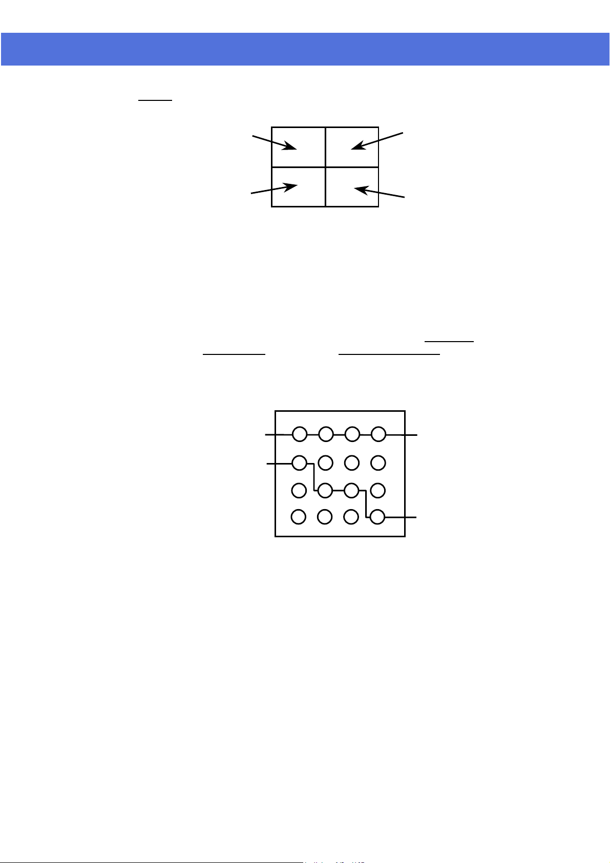
Click the 4-Screen mode button to select this mode.
Four cameras can be selected for display simultaneously.
Click the camera buttons to select camera(s) to display in this mode.
The down buttons will light up in yellow to indicate the display status.
The camera display in 4-Screen mode is assigned as the following figure for easy
operation.
Camera 1
Camera 3
Camera 2
Camera 4
Figure 3-1
Page 11 of 72
Page 13
VisionNet SW-80 User Menu
Hints:
Camera 1,2,3,4
Camera 9,10,11,12
Camera 5,6,7,8
Camera 13,14,15,16
Figure 3-2
Tip:
To make the most use of the 4-Screen real time display of the unit,
consider the arrangement of your camera connections to the unit.
You can think of the cameras that you want to display
simultaneously in a 4-Screen mode as a group. Connect the
grouped cameras to the inputs of the unit in a horizontal
arrangement instead of in a vertical arrangement.
Example: Two possible horizontal arrangements of the grouped
cameras are shown in Figure 4.
9 5 1 13
10 6 2 14
11 7 3 15
12 8 4 16
Camera Inputs in Rear Panel
Group 1
Group 2
Figure 4
(Shown as the standard version of SW-80 system product, for packaged
products, the actual location of camera assigned will vary with different
system)
Page 12 of 72
Page 14

q
VisionNet SW-80 User Menu
Multi-Screen mode
The multi-screen buttons can be pressed
simultaneously to superimpose the
uad-quad selections.
A group of four multi-screen buttons is implemented for multi-screen display
control.
The multi-screen buttons are enabled only under the 4-screen mode.
You can click on any of these mode buttons to further split any quadrant of
the original 4-Screen display into a smaller quad display (quad within a quad).
All multiscreen mode buttons can be selected simultaneously.
Example:
Using the following multi-screen buttons configuration (as that shown
in Figure 5-1) as an example, the camera display will be assigned as
Figure 5-2.
Select 4-screen mode to
enable multi-screen selection
1 2
3 4
9 10 13 14
11 12 15 16
Cameras 5,6,7,8
8-Screen mode
Figure 5-1 Figure 5-2
Click on the 8-Screen mode button to select this mode.
All cameras will be displayed simultaneously at first time entry to this mode.
Click the camera buttons to select or de-select camera(s) to display in this mode .
The down buttons will light up in yellow to indicate the display status
Click on the surrounding (small) screen will cause the camera on display to be
swapped with the one at the center(Large) screen. Keep doing the swapping until
the designed cameras is assigned to the respective screen. The assignment will be
maintained even if there is a momentary change to other multi-screen modes, but
it will return to its default by logging out and on again.
The camera display in 8-Screen mode is assigned as in Figure 6-1 by default.
1 2 3 4
5 6 7 8
9 10 11 12
13 14 15 16
1
2
3
4
5
68 7
Figure 6-1 Figure 6-2
Page 13 of 72
Page 15

VisionNet SW-80 User Menu
16-Screen mode
Rapid Zoom
Full screen display
Sequence
Click on the 16-Screen mode button to select this mode.
All cameras will be displayed simultaneously.
The camera buttons will then all light up in yellow to indicate the selection of all
the cameras.
The camera display in 16-Screen mode is assigned as in Figure 6-2
You can switch any camera display to one-screen display mode rapidly.
Simply double-click on the desired image on screen, and the image of that screen
will be switched to “one screen” mode immediately.
For an example, you can change the camera 3 display from 4-Screen display
mode to 1-Screen display mode by double click the camera 3 image on screen.
You can return to the original display mode by a click on the previous display
mode button.
Click on the “Full Scrn” button to display the video(s) in full screen.
All the control panels and buttons will be hidden and only videos will be
displayed on the screen in order to fully utilize the display area of the monitor.
Right-mouse click on any part of the full screen to restore the normal control
panel display.
Click the “SEQ” button in the “DISPLAY” panel to toggle the sequence function
on or off.
The indicator of the button lights up in yellow to indicate the sequence function.
The function of sequencing is effective for all display modes, except for the 16Screen mode.
The user can select individual camera(s) for sequencing display.
For the sequence parameter setup and the implementation example, please see the
“Display Sequencing” under “Option Setting” section of this manual.
Note:
When the unit is in sequence mode, all the camera selection buttons
inside display panel will be inhibited. You should click the “SEQ”
button to off position to re-gain manual access of the camera
selection.
REMOTE ONLINE VIEWING AND PLAYBACK RECORDED VIDEO
The Intelligent Remote Player
SW-80 Server Button
An intelligent remote player is designed to provide online viewing and
playback recorded video functions in the remote client station.
While the remote client is doing online viewing, the SW-80 screen
automatically switch to 16-screen display mode.
Please refer to the Intelligent remote player manual for detailed operation
procedure of the intelligent remote player.
The apperance of the icon of the SW-80 button on the screen indicates
the server is on for Online Viewing & Dialing in. The user can turn off
this service by clicking the button and click the "close" icon on the
menu bar of the control window.
To re-open this service, click the "Utility" button and select the "DSR
SERVER" function. The icon will re-appear in the Main Screen.
Page 14 of 72
Page 16
VisionNet SW-80 User Menu
RECORDING
Storage drive
Recording modes
Multiple camera recording
The recorder control panel
SW-80
recording for “Normal” backup mode of operation.
SW-80
for “Archive” backup mode of operation.
Notes: The active (selected) drive should be assigned properly before the
overall backup and restore operation is executed. Assign the target drive inside
the “Insert drive” message box by clicking the “Swap Drive” button while the
system is operated in “Archive” backup mode. Go to the “Option Setting”
chapter for further detail.
According to the recording initiation method, four different modes are
available for selection in SW-80
All cameras can be recorded independently.
Each camera will be recorded into individual video file(s).
The camera ID, start date/time, and the recording mode of the individual
camera will be logged with database management.
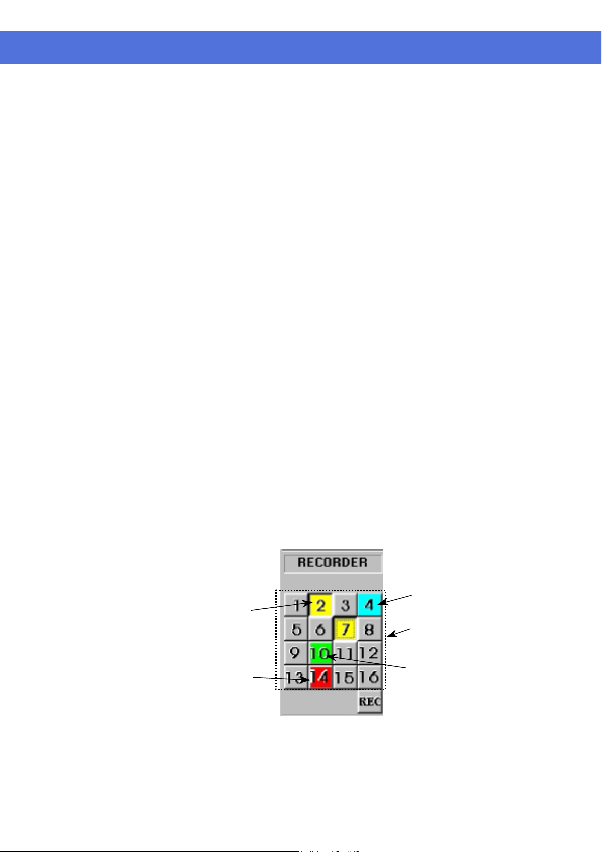
SW-80 has
the unit for recording control with enough indication.
There are sixteen camera buttons in the “RECORDER” panel, all of which can
be toggled on or off.
Each button has four built-in indicators with different colors to indicate
different recording modes and statuses.
The available indicator colors are yellow, red, light blue and green,
respectively.
will automatically detect available fixed hard disk(s) in the unit for
will directly record into the active removable hard disk in the unit
Instant recording
Scheduled recording
Pre-alarm recording
Alarm recording
a “RECORDER” panel (see Figure 7) to let the user interact with
Yellow -- the corresponding camera is performing instant recording, which
is initiated by the pressing down of the button manually.
Red -- the corresponding camera is under alarm recording, which is
initiated by the alarm input or by motion detection.
Light blue -- that the pre-alarm function of that camera is activated.
Green -- the corresponding camera is under scheduled recording, which is
controlled by the programmable timer.
Camera button pressed down
to start instant recording.
Yellow indicator represent
instant recording of the
camera is taking place.
Red indicator represent
alarm recording of the
camera is taking place.
Figure 7
Light blue indicates that
pre-alarm is activated
Camera buttons
Green indicator signifies that
timer recording of the camera is
taking place.
Page 15 of 72
Page 17
VisionNet SW-80 User Menu
Instant recording
Instant recording is the most interactive way and easy to use recording method.
It is designed to start instantly to capture some unexpected special events.
It works as a complement of the scheduled background recording.
You can simply toggle on or off the video recording by clicking the camera
button in the “RECORDING” panel.
The down button with a yellow light indicator indicates that the camera is
under instant recording.
Instant recording parameters of each camera can be programmed.
Please see the section of “Recorder Setting” for parameter setup.
Tip:
Instant recording is expected to work in a real frame rate for short
time recording while scheduled recording is expected to work in a
lower frame rate for longer time recording.
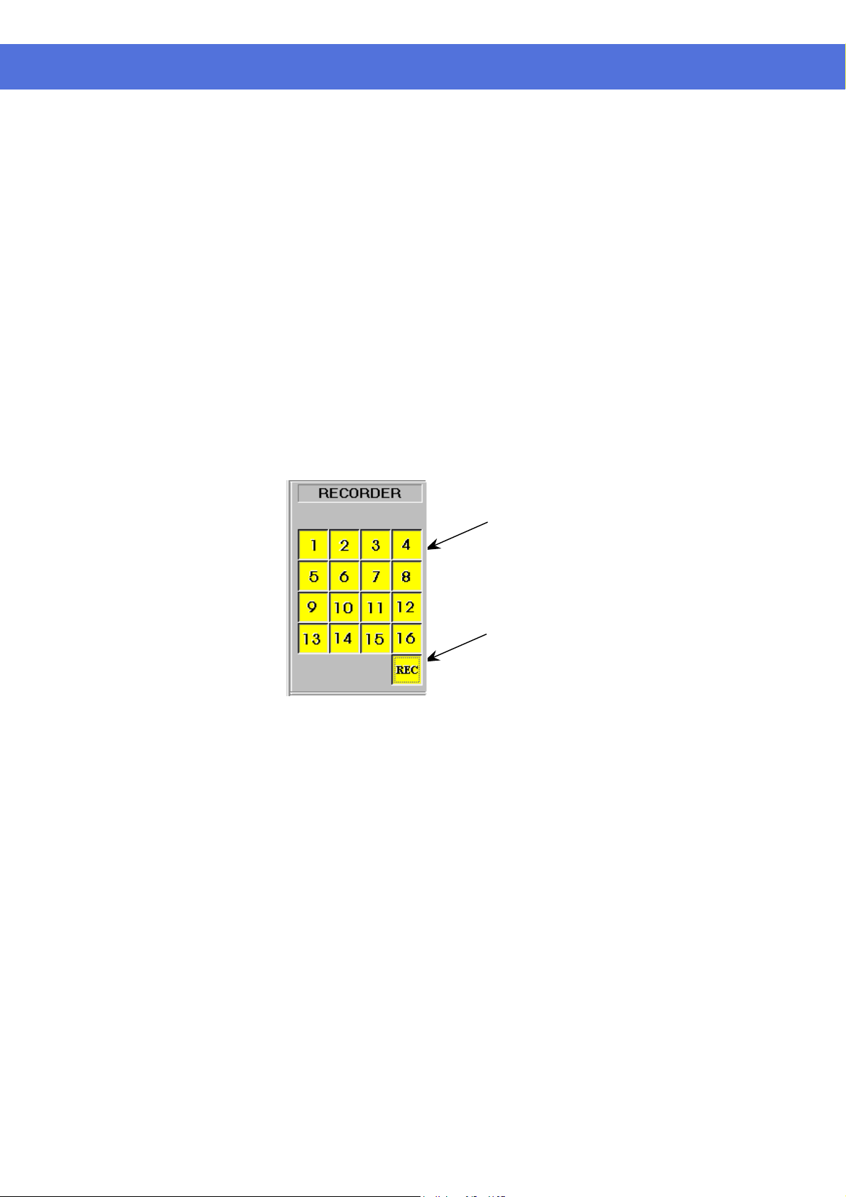
For quick, instant recording of all installed cameras, the user can click on the
“REC” button in the “RECORDER” panel (as shown in Figure 8 on the lower
right hand corner) to activate/deactivate this function.
Click on any camera
button to start instant
recording of that
camera
Figure 8
One quick button click
to start all cameras for
instant recording.
Another click would
release all cameras
from instant recording.
Page 16 of 72
Page 18

VisionNet SW-80 User Menu
Alarm recording
Pre-alarm recording
The alarm recording will be triggered by the alarm inputs or the motion
detection.
Sixteen alarm inputs are assigned one to one corresponding to the 16 cameras.
Once the alarm is triggered either by the alarm input or the motion detection,
the corresponding camera will start recording automatically.
A red indicator indicates that the camera is now under alarm recording.
The alarm recording function of an individual camera can be disabled, also the
alarm recording duration and the frame rate of each camera can be
programmed individually.
Please see the section of “Recorder Setting” for the setup details.
Note:
Only the logon username of “SUPER” can access the utility for
alarm enable and alarm recording parameter settings.
Tip:
In order to verify that alarm recording of particular camera(s) is
actually taking place, the user can try and see if the red indicator
light(s) in the RECORDER PANEL is/are being displayed.
Pre-alarm recording works together with the alarm recording. Pre-alarm
function enables you to capture images before the alarm event is happened.
Pre-alarm allows images to be temporarily recorded for a short period of time
(1 to 60 second) at normal situation. Once an alarm is actually being triggered,
the pre-alarm images become permanent files, which can be retrieved and
played back.
Using “Play Search” function can playback the pre-alarm images.
The pre-alarm function is setup in the “Alarm”, “Recorder Setting” inside
“Utility”.
You can activate the pre-alarm function accordingly when the alarm function is
selected.
Please see the section of “Recorder Setting” for the setup details.
Note:
Pre-alarm images are stored into two temporary files alternatively
under normal situation. Therefore, when alarm is being triggered,
there will be two pre-alarm files accompanies with the alarm file.
Tip:
Pre-alarm recording provides an effective way of using the hard
disk storage:
The pre-alarm image will be kept in the hard disk only when an
alarm is actually taken place.
Since it provides the image happened before the alarm, you can
review what is happening right before the alarm triggering, it is
no longer necessary to do schedule recording at all time.
For an example, the door was opened, and it triggered the alarm
recording and you can also know who opened the door by playback
the pre-alarm recording video.
Page 17 of 72
Page 19

VisionNet SW-80 User Menu
Scheduled recording
A programmable timer is implemented for scheduled recording.
SW-80 support both weekday and weekend scheduled recording.
The timer will start and stop scheduled recording automatically according to
your input.
A green indicator indicates that the camera is recording under the timer control.
The default recording duration value is 0, which represents infinity or continue
recording.
During schedule recording, you can manually over ride to instant recording
mode by pressing down the camera button. The indicator will change to
yellow to indicate that the camera is under instant recording.
However, it will automatically resume scheduled recording once you click the
camera button again to turn off instant recording of that camera. The indicator
will then resume to green.
Please see the section of “Recording Setting” for the setup and implementation
example of the schedule recording.
Note:
Only the logon username of “SUPER” can access the utility for
configuring settings of scheduled recording parameters.
Tip:
The user can verify if scheduled recording is actually taking place
by trying to see if the green indicator light(s) in the RECORDER
panel is/are lit.
Page 18 of 72
Page 20
VisionNet SW-80 User Menu
PLAYBACK
Playback the video
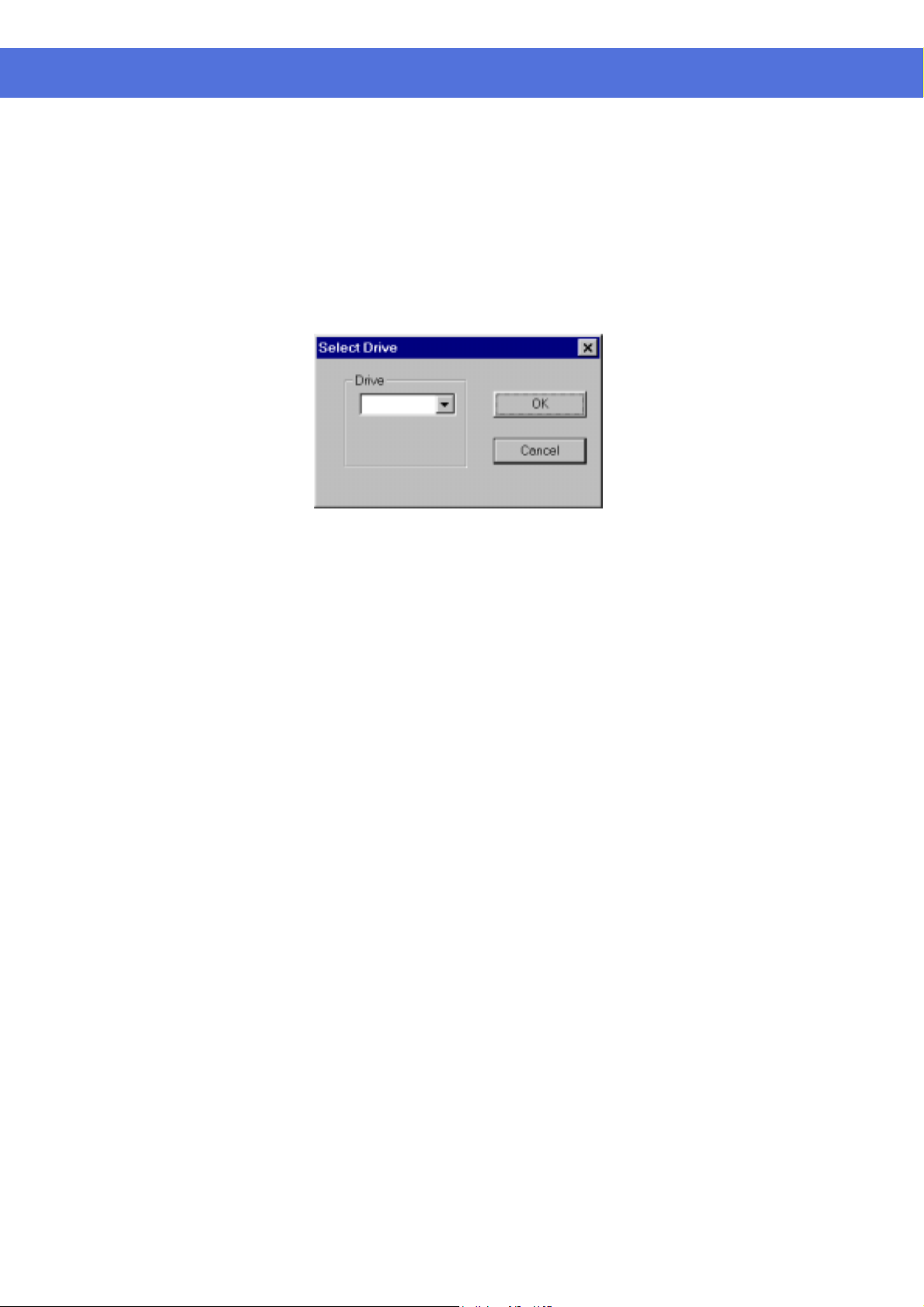
Figure 9
Select Drive
Recorded video in all hard disk(s) and removable disk(s) can be retrieved for
playback.
Click the “Play Back” button in the main screen to activate the Select Drive
dialog box. (as shown in Figure 9)
Click the Downward arrow and select desired drive no. C, D, E….from the pull
down list
Page 19 of 72
Page 21
VisionNet SW-80 User Menu
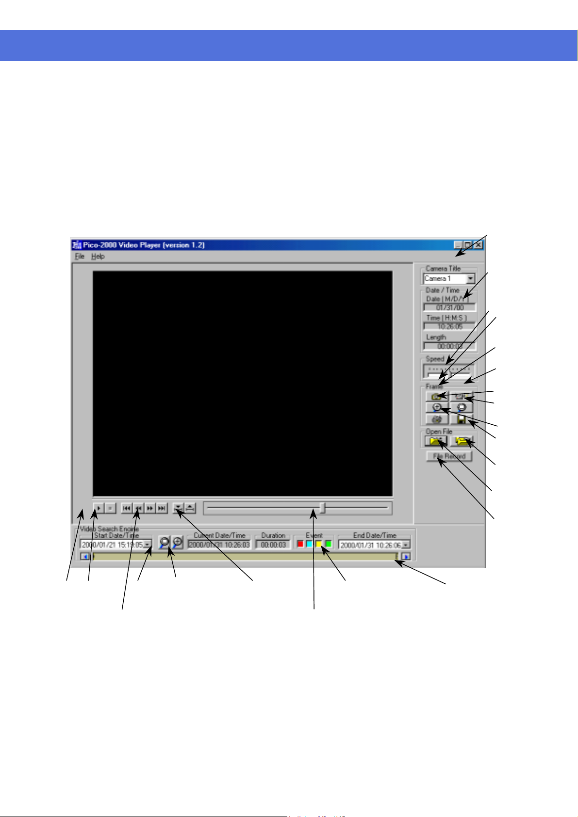
The video player
(Figure 10)
List File Record
Click the "Play search" button in the PROGRAM and select which camera
to playback by the play search functions of the SW-80. Once the video is
selected, click the "Play" button to invoke the video player.
Click the “File Record” button in the Video Player Dialog Menu bar to display
the list of video files for the selected camera. Click on the desired file from the
list and Click Open File Button to start the playback.
The File List will change as the video search engine is manipulated, to match
with only those files appear on the video bar window. Click the Reset Button to
resume the List of all files on Selected Camera title.
Camera
Title
Absolute
Date/Time
and length
of the video
Speed control
for playback
Frame
operation
Snap
Shot
Video
Mode
Zoom In
Zoom
Out
Print
Save
Open
Multiple
Files
Open
Single file
Play
Stop
Steps advance and go to begin/end
Reset Magnify
Figure 10
Begin/end marker
Scroll bar for manual search
Event(s) under
search
Display
Video Files
Video Search Engine (see following
page for detail description)
Page 20 of 72
Page 22

VisionNet SW-80 User Menu
Video playback controls
Playback camera control
Absolute date/time and length display
Playback speed control
Rewind and replay
The video file selected in “Play Search” will be loaded and played automatically.
Use the video playback controls beneath the video image to control the video
playback function.
User can stop the video and use the scroll bar to search the video if needed.
Press the “two-arrow” keys to advance one frame at a time.
Using the camera title control box can select the camera by name or title for
playback. Click the downward arrow and click the desired camera for playback.
During other playback operation, repeat the same procedure to select the new
desired camera for playback, the playback action of the previously selected
camera will terminated.
(Simultaneous playback of two or more recorded videos is possible by invoking
the playback operation from the main menu but this is not recommended.)
The absolute date/time of the playback and the length of the video will be
displayed on the control panel.
Using the sliding control box can adjust the playback speed. Drag the control
button to the right side to increase the playing speed. Drag it left to decrease the
playing speed. The normal playback speed is indicated in the speed control box
when the control button is put in the middle.
Using the Begin/end Marker can select a portion of the current video file to be
replay in a loop. Drag the scroll bar (Scroll bar for manual search) to the desired
beginning position, click the “Begin” button to enter the marker, then repeat the
process to enter the “end” position with the “end” marker button. Click “Play’
button to begin the playback with auto-rewind.
Frame mode for print and save a frame
Return to Video
mode
Use “Snap shot” to grab a frame from the video and enter the frame operation
mode.
User can select area of interest using mouse movement and the mouse left button
and then click “Zoom” button to zoom in the image. Click “Unzoom” to return
to normal display.
Click the “Print” button to print out the image captured.
The frame can be saved to floppy disk in drive A by clicking the “Save” button.
The saved filename has the following format:
x-mmddyy-hhmmss.bmp
x: camera number
mmddyy: month/day/year
hhmmss: hour:minute:second
bmp: bmp file extension
Tip:
The user can set up printer properties for printing hard copy and
previewing the hard copy before actual printing.
Click the “Video mode” button to go back to video playback mode.
Page 21 of 72
Page 23
VisionNet SW-80 User Menu
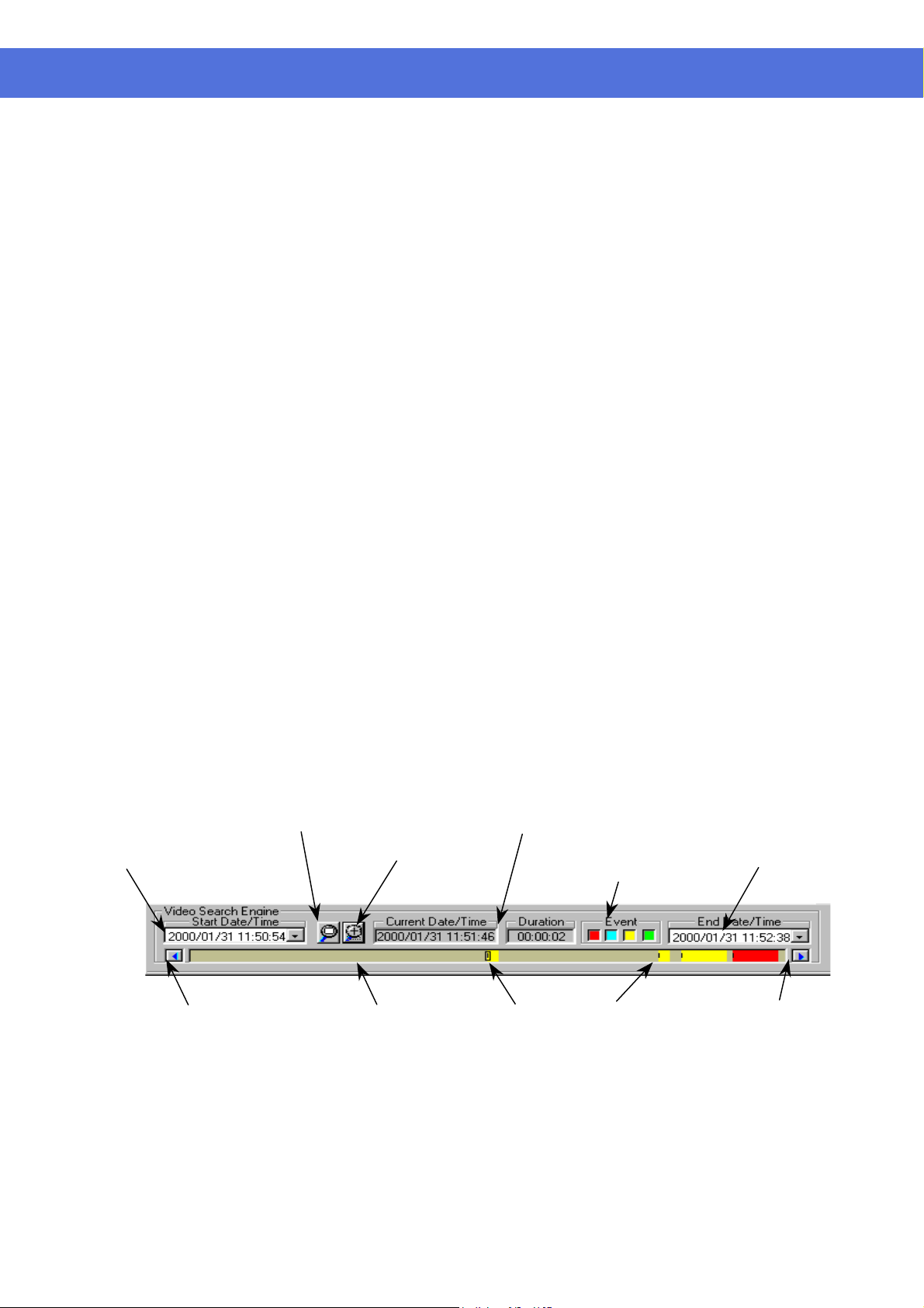
The video search
engine*
Playback the current file
Open the video files and playback continuously
A video search engine is a separate functional block for video searching of a
camera graphically.
Two date/time pickers are used for begin and end date/time input and indication.
All the available recorded videos within this date/time limits will be presented
inside the video bar window.
Different types of video will be presented in different colors, codes as follows:
Yellow - Instance recording video
Green - Schedule recording video
Blue - Pre-alarm recording video
Red - Alarm recording
Down the event-search button to select types of event under search, they are
color coded in the same manner the event. By default all types are selected when
the Player is activated.
A marker, which is a small rectangle box inside the video bar window (which
shows multiple video files), marks the “video header” position of the video.
Point the mouse cursor and click inside the video bar window, the video marker
will snap to the nearest “video header” position of a video.
A date/time display box in the middle of the video search engine displays the
current date/time value of the marker position.
Click the “Open Single file” icon button to open the marked video for viewing.
Once the button is pressed down, the video will be playback until the end of the
file is reached.
Click the “Open Multiple files” icon button to open the marked video for
viewing.
Once the icon button is pressed down, the videos will playback one by one
continuously. Or user can click the “Open Multiple files” icon button to release
the button to disable the continuous playback.
Search the video interactively
Begin Date/time picker
Left arrow for
scroll control
*The video search engine is designed to search the available video in the selected hard disk(s) only.
User can directly input the begin/end date/time by using the “begin and end
date/time picker” to select interesting portion of the video bar window to show in
more detail.
User can also use the mouse click to mark the interesting “video header” and then
click the “Magnify +” icon to magnify the interesting portion.
Use the left and right arrow icon buttons to scroll the video bar window.
Repeat the mark and magnify actions to search for the video of interest.
Click the “Magnify all (Reset)” icon to resume to present all available video.
Magnify All
(Reset)
Video bar window
Current Date/Time of the marker position
Magnify +
Marker position
Event(s)
under search
Video header
End Date/time picker
Right arrow for
scroll control
Page 22 of 72
Page 24

VisionNet SW-80 User Menu
MOTION DETECTION
Motion detection
Set up the motion detection
An advanced digital video-processing algorithm is used to implement motion
detection function in SW-80. The motion detection is designed to
automatically detect any activities within a selected detection area(s), and to start
recording of that camera when activity is detected inside the detection area(s).
Right click the mouse button on the video screen of the camera you want to set
motion detection.
A “Motion detection setting” dialog box will pop up for motion detection setting.
Selected area for
motion detection
Grid superimposed
on the video screen
Page 23 of 72
Page 25

VisionNet SW-80 User Menu
Set detection area
Indicate the detection area
Set sensitivity for motion detection
The first thing to do is to input the detection area(s). Click the “Detection area
setup” button to show the grid on video screen for detection area selection.
Simply click on any spot to select/de-select the grid(s) to form detection area(s)
of any shape in the video screen for motion detection.
The “Select all” button is used to rapidly select the whole video screen for
detection.
The “Clear all” button is used to de-select all the selected areas.
If you want the detection area to be presented on the video screen during normal
operation, click the “Show at all time” button.
If you don’t want the detection area to be presented in the video screen during
normal operation, click the “Not show” button.
Click the “Sensitivity setup” button to display the “activity blocks” for sensitivity
setup.
The “activity blocks” will superimpose on the moving object to highlight the
activities on the video screen.
You can adjust the sensitivity by using the sensitivity control box. Click the up
arrow button to increase the sensitivity and click the down arrow button to
decrease the detection sensitivity respectively.
The sensitivity value display inside the control box, which is an arbitrary value,
indicates the relative detection sensitivity.
Adjust the sensitivity by monitoring the “activity blocks” on the screen to
determine that the sensitivity is adjusted to an optimal condition for motion
detection and without false alarm.
User can check the “Show within detection area” button to confine the “activity
blocks” only to display within the detection areas you have selected.
Detection interval
Recording time extension
Enable the motion detection function
The occurrence of motion is detected by correlating the successive frames of the
video. The “Detection interval” control box can adjust the detection interval
between these successive frames. The detection interval is in unit of 100mS.
The default value is at 200mS.
The motion detected in the detection area(s) will be used as an event to trigger
the alarm recording of the corresponding camera.
Once the recording is started, it will continue with an extension time even the
motion is stopped.
This extension time can be adjusted by using the “Post motion rec.” control box.
The time interval is in unit of second show inside the control box and the default
value is 3 seconds.
Check the “Motion detection enable” box to enable the motion detection function
once you have set all the parameters.
(User can temporarily disable the motion detection by uncheck the “Motion
detection enable” box. All the settings of the motion detection will stay
unchanged, which let the user to enable the motion detection back again
afterward more easy).
Click the “Close” button, the corresponding camera button in the display panel
will light up with a yellow grid indicator to indicate the motion detection
function.
The detection area will be presented in the video screen if the “Show at all time”
button is checked.
Page 24 of 72
Page 26

VisionNet SW-80 User Menu
Yellow grid indicator
indicates that the motion
detection is enabled
Tips Use the same image resolution for displaying and recording to get better and
stable performance of the motion detection function.
When display at QUAD mode; use “High” resolution mode for motion
detection recording.
When display at 16-screen mode; use “Low” resolution mode for motion
detection recording.
When display at one screen mode use “Supper” mode for motion
detection recording.
Without displaying the motion detection camera.
Page 25 of 72
Page 27

VisionNet SW-80 User Menu
PAN-TILT ZOOM CONTROL
Pan-tilt Zoom
Driver Mode Setting
Using the pan-tilt zoom function, the camera can zoom in or out to adjust the
view angle of the camera for a better image, or it can pan and tilt the camera to
different position of interest for better surveillance.
Click the PTZ icon button besides the “EXIT” button to activate the PTZ panel.
Note:
The camera number setting of the On Site Receiver Driver (OSRD)
should be set up correctly with the same camera number as the
camera attached to it.
Right click the mouse on anywhere of the PTZ Panel, a menu will appear which
can select the MODE, PORT SETTING or EXIT.
Select the MODE item, a sub menu will show up the item MV912RS, Old OSRD
Code, PTZ Receiver Driver and/or other available Custom’s option. After your
selection, a tick will appear left to the item.
Note :
To run the pan-tilt function properly, you should match the OSRD
with the selected protocol.
Page 26 of 72
Page 28

VisionNet SW-80 User Menu
Port Setting
Camera Selection
Monitor Selection
Speed control
The port setting is about the COM port (the serial port) connection preferences.
The default of the connection preferences is as the following figure.
Please refer to individual OSRD connection preferences for correct setup of the
connection preferences.
The camera selection box in the PTZ control panel is for selecting the desired
camera for PTZ control.
While the MV912RS protocol is selected, there will be a monitor selection box in
the PTZ control panel.
The speed of movement of the pan-tilt head can be controlled. The slide bar is to
control the speed of movement.
Pan-tilt zoom control
Pre-position
Once the camera is selected, click the arrow buttons for corresponding direction
movement, the focus and zoom control.
The positions of the pan tilt head can be saved so that camera can repeat its
position when wanted.
Set Pre-position
Use the “Pre-position” box to enter the pre-position number.
Once the number is selected, pan/tilt the camera to a desired position and then,
press “Set” button to assign this position into that particular pre-position number.
Show Pre-position
Use the “Pre-position” box to enter the pre-position number.
Once the number is selected, press the “Show” button to send the camera to the
saved pre-position.
Pre-position hot keys
Four hot keys are implemented for four frequently used pre-positions.
Once programmed, press these hot keys will send the camera to it’s pre-position
accordingly.
Page 27 of 72
Page 29

VisionNet SW-80 User Menu
UTILITY FUNCTIONS
Access to Utility Functions
Re-activate the disabled Housekeeping Functions
When the user logged on as “SUPER”, he/she is authorized to use the Utility
functions.
However, if the user logged on as “OPERATOR”, the Utility button will be
disabled to prevent the password and some other system and recording settings
from being modified by the operator.
Click on the Utility button on the main screen, and the Utility menu will then pop
up as shown in Figure 12.
The Housekeeping Function of the Utility Menu us disabled in case the
PROGRAM is operated in the "Archive" Backup mode. To activate those build-in
housekeeping functions from SW-80, switch the system back to "Normal" backup
mode. Go to the Option Setting Chapter for further details.
Figure 12
Page 28 of 72
Page 30

VisionNet SW-80 User Menu
CAMERA CONFIGURATION
Camera title assignment
Maximum no. of camera imposed by software
Check the active connected cameras
Apply the camera title
To assign the Camera title correctly for individual camera connected to the
SW-80
button for camera title input. A camera setting dialog box (as seen in Figure 13)
will be displayed for camera title input.
The default camera title is Camera 1 to Camera 16 respectively.
Click the desired input area for data entry, and then input the camera title
accordingly. User can use the Backspace and Del keys in the keyboard to edit
the text in the input field.
The max. no. of cameras is limited to 4 for model SW-80 and for model SW-8001 etc.
This is to match with the design no. of cameras shown in the corresponding part
of the generic model no. The camera assignment check box(es) will turn to Grey
color and no manual assignment is possible.
The “Active” check box should be unchecked for the non-connected camera
inputs.
When the “Active” check box is unchecked to the Cam ID, then the
corresponding buttons in the “Display” and “Recorder” panels will be
to stop the display and recording function of these camera inputs.
Click the “Apply” button to apply the camera titles right away.
Click OK to confirm the inputs and close the dialog box.
Or you can click “Cancel” button to close the dialog box without change.
The camera title will be displayed on the screen to indicate the camera title.
The camera title will also be used for the video playback search.
The camera number buttons will be disabled in the “Display” and “Recorder”
panels for the non-connected camera inputs.
unit, Click the “Utility” button and then select the “Camera Setting”
disabled
Figure 13
Page 29 of 72
Page 31

VisionNet SW-80 User Menu
RECORDER SETTING
The recording parameters
Frame rate
The start and end times for scheduled recording
The instant recording, alarm recording and the scheduled recording modes
should have their individual sets of recording parameter settings.
Click the “Utility” button and then select the “Recording Setting” to start
program the recording parameters of individual cameras for different recording
modes.
Frame rate is the most important parameter for recording setting.
The value of frame rate is in f/s (frame per second), which controls how many
frames will be recorded for every second.
SW-80 provides a selection list for frame rate input. The possible frame
rates are 25, 12.5, 8, 4, 1, ½ and 1/60 frames per second respectively.
The ½ frame per second frame rate selection is interpreted as one frame
recorded every two seconds, and a 1/60 frames per second frame rate selection
means the recording of one frame every 60 seconds.
Note: The actual frame rate of recording will be same as this setting if the
system resource at the condition taken care of other system setting
permits. However, the SW-80 may regard this setting as the target
maximum frame rate.
The start time and end time is needed for scheduled recording.
The input time is in the 24-hour HH:MM format.
The factory default setting of the weekday recording start time is 0:0 and the
default end time is also 0:0.
Under this default setting, the camera will start at Monday 0:0 and end at
Tuesday 0:0 and then start right away at Tuesday 0:0 and repeat all over again
for the rest of the weekdays. Therefore, weekday recording will record at all
times from Monday 0:0 through Saturday 0:0.
Weekend scheduled recording also has the default 0:0 start time and 0:0 end
time.
Under default start and end time the unit will start recording at Saturday 0:0
and end at Monday 0:0.
Page 30 of 72
Page 32

VisionNet SW-80 User Menu
Instant recording
Select the Instant tab inside the Recording Setting menu and a screen similar to
that of Figure 14 is shown.
Input the desired frame per second for individual cameras.
The default frame rate is 25 frames per second.
Click OK to confirm the input and close the dialog box or click the X box in
the upper right corner to close the dialog box after use.
Tip:
Eight frames per second or above is recommended for instant
recording to capture real-time video.
Click OK to
confirm input
Recording setting for instant recording
Figure 14
Click this arrow to
show the list
Use scroll bar to
see more selections
Page 31 of 72
Page 33

VisionNet SW-80 User Menu
Alarm recording
Pre-alarm recording
Select the Alarm tab inside the Recording Setting menu (a screen similar to that in
Figure 15 would then pop up).
Check the “ON” box for corresponding camera to enable the alarm input and the
alarm recording function.
Input the alarm recording duration in the (in sec) column.
Check the Nopen (Normally open) box if the switch connected to the alarm input is a
normally opened switch.
Input the frame per second for individual cameras. The default frame rate is 25 f/s.
Check the “ON” box in the pre-alarm column to enable the pre-alarm function of the
corresponding camera(s).
Input the pre-alarm duration from one to 60 seconds.
Every time when the alarm is triggered, the pre-alarm recording image will be saved
into a permanent file, which can be retrieved for playback.
Click OK to confirm the input.
Tip:
Pre-alarm lets you review images prior to the actual happening of
the alarm event. Also, pre-alarm keeps the images only when the
alarm is actually taking place, so that storage space can be used
more effectively. This mode is more effective than that in
scheduled recording.
Check the cameras
for alarm recording
Input recording time
Check the box if the
sensor device is
normally open type
Input frame per
second
Figure 15
Page 32 of 72
Page 34

VisionNet SW-80 User Menu
Scheduled weekday recording
(Figure 16)
Check the cameras for
weekday recording
Select the Schedule Weekday tab inside the Recording Setting menu.
Check the camera you want to record.
Input the start time and the end time for scheduled weekday recording.
Input the frame per second for individual cameras.
The default frame rate is 1 frame per second.
Click this arrow to
show the list
Use scroll bar to
see more selections
Figure 16
Page 33 of 72
Page 35

VisionNet SW-80 User Menu
Scheduled weekend
recording
(Figure 17)
Check the cameras for
weekend recording
Select the Schedule Weekend tab inside the Recording Setting menu.
Check the camera you want to record.
Input the start time and the end time for scheduled weekend recording.
Input the frame per second for individual cameras.
The default frame rate is 1 frame per second.
Tip:
Scheduled recording is a background recording activity of the
recorder. A lower frame rate for scheduled recording will much
prolong the recording time. It is recommended to use frame rates
of four frames per second or lower for scheduled recording.
Click this arrow to
show the list
Use scroll bar to
see more selections
Figure 17
Page 34 of 72
Page 36

VisionNet SW-80 User Menu
Example 1 Suppose you want to start and stop your recording on one camera
within the same day every weekday, say 9:00 to 17:00 from Monday to
Friday. You should go to the schedule weekday recording menu, check
on the desired camera, enter 9:00 in the start time input, 17:00 in the
end time input, then enter the frame rate you want and finally click OK
to confirm.
You will see the green indicator light of that camera in the RECORDER
panel at 9:00 to 17:00 to indicate that scheduled recording is taking
place.
Example 2 Suppose you want to start recording one camera at 18:00 and stop at
6:00 the next day, for everyday from Monday to Friday.
You should go to the schedule weekday recording menu, check on the
desired camera, enter 18:00 in the start time input, 6:00 in the end time
input, then enter the frame rate you want and finally click OK to
confirm.
In this case, the recorder will start at Monday 18:00 and then stop at
Tuesday 6:00 and the schedule continues every weekday. While on
Friday, the recorder would start at 18:00 as usual but it would stop on
Saturday at 0:0.
Therefore, you should enter another schedule for weekend recording to
fit your scheduled planning as a whole.
Audio Recording
Go to the "Options Setting" Chapter for further details.
Page 35 of 72
Page 37

VisionNet SW-80 User Menu
OPTION SETTING
Display Sequencing
Click “Utility”, “Option Setting” and then “Display” to get to the sequence
display menu.
Enter the dwell time for sequencing duration. The default dwell time is 1 second.
Check the camera(s) you want to display during sequencing.
Click Apply to apply the input parameters right away.
Click OK to confirm and close the dialog box.
For sequencing operation please see the “Display” section of this manual.
Example:
The cameras 3, 4, 5, 7, 8, 9, 12, 13, 14, 15, 16 are checked in Figure 18.
Figure 18
While in the 1-Screen mode, the sequence will be performed as follows:
3 4 5 7 8 9 12 13 14 15 16
While in the 4-Screen mode, the sequence will be performed as follows:
3 4
9 12
5 7 8
13 14 15 16
Page 36 of 72
Page 38

VisionNet SW-80 User Menu
Image resolution for all recording
Select the Recording tab in the Option Setting menu (Figure 19).
The Resolution check box controls the image resolution for recording.
Super recording mode set the recording in the full resolution, which is 640 pixels
by 480 pixels in PAL and NTSC system.
High recording mode set the recording in a standard resolution, which is about
384 pixels by 288 pixels in PAL system and is about 320 by 240 pixels for NTSC
system.
Low recording mode set the recording in a low resolution, which is about 192
pixels by 144 pixels in PAL system and is about 160 by 120 pixels for NTSC
system.
Tip:
Check the “High” box in Resolution for most of the case. It is to
optimize the system performance and storage usage.
Recording mode selection
Attach Audio to Camera
Drive capacity
Figure 19
Linear recording mode:
When linear mode is selected for recording, the recording (alarm, pre-alarm,
instance and schedule) will stop automatically when the storage device(s) is all
used.
Circular recording mode:
When circular mode is selected, the recording will keep on by automatically over
writing the oldest files once the storage device(s) is full. However, the alarm
image file(s) will be protected in this mode.
For Models with Audio Recording support only, make sure the system is properly
set up for audio recording, equipped with an audio pickup device and have the
volume control setup for both recording an playback etc. The message box is
opened for input. Enter the camera no. for attaching recorded audio data. When a
“0” is entered, no audio recording will be performed.
The audio data is now setup to be recorded and playback in sync. With the video
part of the selected camera.
The total space, free space and the used space of the selected drive are displayed
simultaneously.
A progress bar is displayed to indicate the usage level of the recorder drive
graphically.
Page 37 of 72
Page 39

VisionNet SW-80 User Menu
Backup function
Normal Mode
Archive Mode
Make sure to select the intended Backup Mode prior the formal use of the
SW-80 system for routine video recording.
Make sure to select the backup drive prior to the backup.
Click on Utility, then Option setting, and finally the Backup tab (Figure 20).
Click the down arrow in the backup drive box to display the available
removable drive(s) for backup and select the desired backup drive.
The removable device can be a DVD-RAM drive or a removable IDE hard
drive.
The user can choose to keep copies on hard disk after backup or not.
Click Apply to confirm and click OK to close the dialog box.
The system is set to "Normal" backup mode as system default. To switch to
"Archive" mode, check the bullet option next to Archive, then Apply and
OK. The SW-80 application should closed and restarted to effect the change.
At the start up on Archive backup mode, the main screen of the SW-80 will
be slightly modified and refreshed as shown in figure 21.
Figure 20
Figure 21
Red
– Indicate the Drive is set Active, being used for immediate video recording
Green
– Indicates the Drive is dismounted, ready for physically taken out
Swap
Drive
Page 38 of 72
Page 40

VisionNet SW-80 User Menu
Swap Drive
(Applicable to Archive
Backup mode of operation
only)
Re-insertion of Removable Drive
Make sure the system is properly setup with two available “Removable Hard
drive” and there is a fixed hard drive to support system operations.
Click the Swap Drive button in the Main Screen and then the “Swap drive”
message box will appear as shown in Figure 22.
Click the down arrow in the Select drive dialog box next to the Remove
button to display the registered removable drive(s) for removal and select the
desired drive. Click Remove button and follow the pop up instruction to
complete the REMOVE process.
The entire drive can be back up (Archive) to other long term storage media
such as the DAT or equivalent device with huge storage capacity but may not
work as fast. This operation on a dismounted drive can be down off-line
(while the SW-80 is closed) or in a separate PC workstation.
Click the Swap Drive button in the Main Screen and then the “Swap drive”
message box will appear as shown in Figure 22.
Click the down arrow in the Select drive dialog box next to the Insert button
to display the registered removable drive(s) for insertion and select the desired
drive. Click Insert button and follow the pop up instruction to complete the
INSERTION (RE-Insertion) process.
If a blank new drive is inserted in the slot, make sure it is of the same make
and configuration as the removed drive for proper operation.
Figure 22
Page 39 of 72
Page 41

VisionNet SW-80 User Menu
System operation data
Click on the System tab in Option Setting menu (Figure 23)
There are two default usernames for SW-80:
Two passwords can be introduced for security use during the logon session. The
users should input the correct password to logon to the system.
You can select the date/time display format to 12-hour or 24-hour format.
Click Apply to confirm the input, click OK to confirm and exit or click Cancel to
exit without any changes.
Check the “Logout continue display/recording” box if you want the image to
continue to be displayed and instant recording still function activated upon logout
SUPER
OPERATOR
and
.
Figure 23
Page 40 of 72
Page 42

VisionNet SW-80 User Menu
HOUSEKEEPING
Backup
The Housekeeping Menu is disabled when the system is set to “Archive” Backup
mode, To revert it to “NORMAL” mode, go to the Options Setting chapter for
further details.
Click Utility, Housekeeping then backup to open the backup menu (Figure 24
Select the camera(s) you want to do backup on.
Check the file(s) you want to backup by clicking on the file list, or you can
backup all files by checking the backup all files box.
You can keep copies on the hard disk after backup by checking the “Keep copies
on hard disk” box.
If you want to clean up old files in the backup device prior to do backup, check
the “Delete all files in the backup device” box.
The free storage capacity of the backup device is also shown in the dialog box.
Click the “Start” button to start the backup process.
Backup progress Indicator
Figure 24
A progress bar will be shown at the bottom of the main screen to indicate the
backup progress. The number of files to backup and the progress will be
indicated accordingly.
Tip:
Use the Play Search function of the unit to playback video of
the backup drive.
Page 41 of 72
Page 43

VisionNet SW-80 User Menu
Remove video files
Click Utility, Housekeeping and then Remove Files tab (Figure 25).
Click the down arrow in the camera box to select one or all cameras.
The camera related video files would then be displayed inside the window.
You can check the file(s) to delete by clicking on the camera title or you can
check the “Delete all files” box to delete all files.
Click Start button to execute the file delete function.
The video files will be deleted to spare storage space and the database will be
updated accordingly.
Note:
Camera Date/Time Event
Filename
Size
Figure 25
The camera column displays the corresponding camera titles
The date/time column displays the record starting date and time
“SCH”, “REC” and “ALM” represents schedule, instant and alarm recording events
respectively.
The filename has the following format:
x-mmddyy-hhmmss.avi
x: camera number
mmddyy: month/day/year
hhmmss: hour:minute:second
avi: avi file extension
The file size in KB
Page 42 of 72
Page 44

VisionNet SW-80 User Menu
Housekeeping tools
Click on the Tools tab to enter the tools utility (Figure 26).
Users are recommended to use the “Run Scan Disk” and “Run Disk
Defragmenter” functions on a frequent basis to optimize and debug the
storage device(s) being used.
Figure 26
Page 43 of 72
Page 45

VisionNet SW-80 User Menu
System Information
Click the System Information button to display the "About DSR" message box,
which shows relevant information about the SW-80 (Figure 27).
Figure 27
Page 44 of 72
Page 46

VisionNet SW-80 User Menu
TOO MANY FILES WARNING
Too many files
warning message
Invoke the message box
Remove the message box
All of the recording will be logged with a database system.
Even a very short video file (such as few seconds long) will occupy as an
entry of the database.
Large number of entry will affect the performance of the database
management.
Therefore, a “Too Many Files Warning” message box is designed to provide
information to the user about the file number.
A warning message and the exact number of file will be displayed in the “Too
Many Files Warning” message box.
The “Too Many Files Warning” message box will automatically pop up when
the number of file is excess the default value.
Or user can press the “Ctrl” “Alt” and “1” in the keyboard, do not use the “1”
key located on the Numeric Keypad, to show the message box at any time to
check the number of file in the unit.
User can close the message box by clicking the “X” icon at the upper right
hand corner.
To permanently disable the message box, user can check the “Do not appear
in the future” box and then click the “X” icon to close the message box.
Once the “Too Many Files Warning” message box is permanently disabled,
user should restart the unit (“Exit”, power down and then power up) to reactivate the message box again.
Tip:
False alarm (including by motion detection) will generate many
small files. It is recommended to setup the unit properly to avoid
false alarm.
When the “Too Many Files Warning” is shown, user should
remove the out dated files to decrease the number of file.
Note:
The number of file is not directly related to the storage space usage
of the hard drive.
Page 45 of 72
Page 47

VisionNet SW-80 User Menu
Setup and the default values
User can adjust the default value of the “Too Many Files Warning” signal.
Right click the mouse button inside the dialog box, and then click “Setting”, a
setup dialog box will be displayed.
Warning string:
The default warning string is “Remove files/use longer duration for alarm
recording”.
Filename string:
The default value is “c:pico\image\*.avi”
Don’t change this default or the warning message will not work properly.
Warning number of files:
The default value is 1500.
Update time interval (sec):
The default value is 5 seconds.
Click “OK” to confirm input or “Cancel” to cancel the change.
Page 46 of 72
Page 48

VisionNet SW-80 User Menu
WORKING AT LOGOFF
Log off
Recording during log off
Click the Log ON/OFF button on the main screen to log off.
Once logged off, the unit will not show any video images. The PROGRAM
logo will then be displayed on the screen.
Note:
You should re-logon with the correct password to regain operation
of the unit.
Note:
In the System menu of Option Settings, check the “Logout
continue display/recording” box if you want the image to be
continually displayed after logoff.
The alarm and scheduled recording functions of the unit will keep on working
during the logged off period.
SW-80 will continue recording even if the unit is under the logged off
condition.
Note:
In the System menu of Option Settings, check the “Logout
continue display/recording” box if you want the instant recording
function to be continually functioning after logoff.
SHUT DOWN THE UNIT
Exit
Make sure that all the current recording jobs of the SW-80 is closed
before shutting down the system to prevent data loss.
Click the EXIT button on the main screen and confirm shutdown.
The system will automatically shut down and power off.
Page 47 of 72
Page 49

VisionNet SW-80 User Menu
SYSTEM MAINTENANCE
Schedule backup and
remove the video file
Compact Database system
The video files in the SW-80 unit should be backup and remove in a regular
basic with a properly setup scheule.
This will insure that the performance of the SW-80 unit is working under its
optimum condition.
It is also a vital procedure to prevent from data lose due to out of storage
space of the hard drive.
As a normal operation, it is recommended that user should log off and turn off
the SW-80 unit in a monthly basic.
This will allow the database to close and then do some optimization and
compacting of the record configuration during the system power up.
Page 48 of 72
Page 50

VisionNet SW-80 User Menu
This is a blank page.
Page 49 of 72
Page 51

VisionNet SW-80 User Menu
This is a blank page.
Page 50 of 72
Page 52

VisionNet SW-80 User Menu
This is a blank page.
Page 50 of 72
Page 53

VisionNet SW-80 User Menu
Appendix I
DSR Configuration at Control Panel
(New feature)
In order to seamlessly integrate the DSR with the Windows environment, a DSR
configuration icon is implemented in the Control Panel of the server machine.
User can go to the Control Panel (Start->Settings->Control Panel) and double click
the DSR configuration icon to invoke the DSR configuration dialog.
A "Logon" dialog box will pop up for password protection. User uses the SUPER
as username and the corresponding password to logon for DSR configuration
operation.
User can configure the DSR prior to run the DSR program.
The available DSR configuration settings are listed in the following table:
Alarm Alert Enable
Enable the Alarm Alert function.
Alarm Files Overwrite Enable
By default, the alarm files will not be deleted during circular mode. However, user can check the
enable box in the dialog to allow oldest alarm files to be deleted during circular recording.
Note:
Motion detection triggered and hardwires triggered alarm files are treated equally as alarm files.
Configuration backup and restore
This utility allows user backup the DSR configuration prior to install or re-installs the DSR
software in order to prevent loss of configuration data. Also, a DSR configuration template disk
can be prepared for easy DSR setup during mass production.
The configuration parameters to be backup include the following items:
Page 52 of 72
Page 54

VisionNet SW-80 User Menu
Camera title, enable/disable
System settings
Recorder settings
Motion detection settings
System retain parameters
Alarm schedule (the one which is currently in use)
Hide DSR
A "Minimize" button will be placed on the top right hand corner of the DSR display window
frame.
User clicks the "Minimize" button to hide the DSR display window.
PTZ control Enable
Enable the PTZ function.
Configure the PTZ control
PTZ User Account Management
Only one user is allowed to operate the PTZ control at a time, a user account with priority level
should be setup for management. Click "Add" button to add a new user with priority level. The
highest level is 1. Select a user and click "Remove" or "Edit" button to remove or edit the user
input respectively.
PTZ Control Hardware Configuration
Select the PTZ receiver driver protocol, RS232 port number, Baud rate (9600 as default value),
data (8 bit as default value), parity (none as default value), stop bit (1 bit as default value) and flow
control.
Page 53 of 72
Page 55

VisionNet SW-80 User Menu
PTZ Driver Model Setting
Select the Model item, a drop down menu will show up the available models.
Note:
Following list are the current PTZ control protocols supported by DSR.
Model Protocol/OSRD/Connection Interface
KALATEL_KTD312 KTD-312 computer interface ASCII Protocol, RS-232 to RS-232
PELCO_ASCII Pelco ASCII Protocol (Revision G), RS-232 to RS-422/485
PELCO_SPECTRA Pelco "D" Protocol, RS-232 to RS-422/485
PHILIPS_AUTODOME PHILIPS (BURLE) Auto Dome RS-232 to RS-422/485
LTC0809 Series
UEL_MV912RS UEL OSRD model of MV912RS
UEL_MV961A UEL OSRD model of MV961A, MV561
PHILIPS (BURLE) On-Site Receiver/Driver, RS-232 to Biphase
LTC8561 Series :
LTC8564/20
LTC8566 Series
ULTRAK_KD6 Ultrak KD6 Auto Dome
VICON_SURVEYOR99 V5UWM , VICON Surveyor99 Camera Dome RS-232 to
RS-422/485 Surveyor99 Series
Note:
The DSR unit provides only RS-232 output connection, all other serial connections by external
converter are provided by the user themselves.
Page 54 of 72
Page 56

VisionNet SW-80 User Menu
PTZ Control Serial Port Setting
The port setting is about the COM port (the serial port) connection preferences.
The default of the connection preferences is as the above figure.
Please refer to individual OSRD connection preferences for correct setup of the connection
preferences.
Select Hard Drive to Record and Disk Space Utilization Control
Select Hard Drive(s) to Record
Default to use all available hard drive(s) for recording.
The C: drive is used for system and memory swapping, it is recommended not to use it for video
recording.
It is recommended to install hard drive(s) with at least 15GB for recording.
Disk Space Utilization Control
Two parameters are being used for disk space utilization control, which are "Reserved Space"
and "File Retention Limit".
The minimum value of "Reserved Space" and "File Retention Limit" are 1.5GB and 2.0GB
respectively.
The "Reserved Space" and "File Retention Limit" values will be increased to 7% and 10% of
Page 55 of 72
Page 57

VisionNet SW-80 User Menu
the disk capacity respectively, when bigger disk capacity is being used.
Increase the value of these parameters will increase the safety margin in order to provide more
reliable recording performance.
Linear recording mode:
Recording will stop automatically when all the selected hard drives' available space is lower than
the "Reserved Space" value.
Circular recording mode:
A separate process for deletion will be started automatically to delete the oldest files when all the
selected hard drives' available space is lower than the "Reserved Space" value. The delete file
process will recover the disk space until it reaches the "File Retention Limit" value.
Time Stamp Enable
User selects and enables date and time overlay to each camera for display and recording.
Video Server User Manager
Prior to use the DSR, the remote online view clients should be registered through the Video Server
User Manager.
Double click the Video Server to invoke the Video Server User Manager dialog box.
Page 56 of 72
Page 58

VisionNet SW-80 User Menu
Check the Password Protection box in the button to enable the password protection of the server.
There will be no password protection for the user to come in if the Password Protection check box
is not checked.
You can add new user, edit the existing user information or delete a user by clicking the
appropriate buttons.
Each user entry has a name, password, time limit for continuous logon and the camera restriction
information settings.
Page 57 of 72
Page 59

VisionNet SW-80 User Menu
Appendix II
Video Transmission Server Function
DSR provides video server function to do video transmission to a remote client machine for remote
online view of the cameras.
The video server supports video transmission over any networking that provides TCP/IP protocol
connectivity.
In order to monitor and control the client user logon, a Video Server control panel is provided.
Press Alt-Ctrl-2 keys together to invoke the Video Server control panel.
The control panel divided into two parts.
The upper window is for the current usage display, which shows the current user and the camera under
viewing.
The lower window is the usage history event log.
Administrator can click on the user ID to highlight the entry and then click Disconnect or Terminate to
end the user logon.
Video Server User Manager
An icon called DSR will be installed in the Windows Control Panel (click Start > Settings > Control
Panel) once the DSR is installed.
Prior to use the DSR, the remote online view clients should be registered by using the Video Server
User Manager.
Double click the DSR icon to invoke the DSR configuration dialog and start Video Server User
Manager dialog box.
Page 58 of 72
Page 60

VisionNet SW-80 User Menu
You can add new user, edit the existing user information or delete a user by clicking the appropriate
buttons.
Check the Password Protection box in the button to enable the password protection of the server.
There will be no password protection necessary for all users to come in if the Password Protection
check box is not checked.
Each user entry has a name, password, time limit for continuous logon and the camera restriction
information settings.
Page 59 of 72
Page 61

VisionNet SW-80 User Menu
Appendix III
Working at Log off Guide
Log Off
Click the Log ON/OFF button on the main screen to log off.
The EXIT button is disabled during log off to prevent accidental or unauthorized termination of the
surveillance function.
Note:
You should re-logon with the correct password to regain operation of the unit after logoff.
Display During Log Off
For logoff display selection, go to the System Menu of Option Settings, check the "Continue Display"
box if you want the image to be continually displayed after logoff.
If you do not check the "Continue Display" box, once logged off, the unit will not show any video
images and the DSR logo will then be displayed on the screen.
Recording During Log Off
Alarm & schedule recording
The alarm and scheduled recording functions of the unit will keep on working during the logged off
period.
Instant recording
In the System Menu of Option Settings, check the “Logoff continue recording” box if you want the
instant recording function to be continually functioning after logoff.
Transmission during Log Off
DSR will continue transmission for remote online view even if the unit is under the logged off condition.
Note:
To disable transmission via Dial-in, you have to turn off the Modem (by switch or by disabling the
Modem driver). Please see detail instruction as mentioned under the Remote On-line Viewing and
Playback Recorded Video section.
PTZ During Log Off
Go to the System Menu of Option Settings, check the Continue PTZ box if you want the PTZ functions
to remain after logoff.
Page 60 of 72
Page 62

VisionNet SW-80 User Menu
Appendix IV
Alarm Alert Modules
Alarm Alert modules are designed to work with the DSR.
Once the DSR receives an alarm triggering, either from alarm inputs or motion detection, it will
activate the alarm alert modules to alert the outside world.
The alarm alert application consists of two software modules, the Alarm Alert Caller and the Alarm
Alert Receiver.
The Alarm Alert Caller runs with the DSR unit and the Alarm Alert Receiver is installed in the remote
machine.
The alarm alert signal can reach the remote machine through dial-up connection, LAN connection or
through Internet connection.
Alarm Alert Configuration
Through Dial-up
connection
Alarm Alert Caller setup in DSR unit
·
Prior to use the DSR software, make a New Connection for the remote unit
inside the Dial-Up Networking folder.
·
Please refer to the Appendix of How to Setup a Dial-up Connection in order to
set up the DSR unit as a Dial-up client machine.
·
After the DSR software is started, press the "Windows" button in the keyboard
to show the task bar.
·
Right click the Alarm Alert icon in the task bar to show the Alarm Alert Caller
Setup window.
·
Select Dial up in the Connection Mode.
·
Click the Setting button to show the Dial-up connection window.
Page 61 of 72
Page 63

VisionNet SW-80 User Menu
·
·
·
Through LAN
Connection ·
·
Inside the Connect to input box, click the down arrow to select connection
from the available connection name inside the Dial-up Networking folder.
·
Make sure to check the Save password box.
Input the IP address of the remote unit in the Alarm Alert Receiver Name/IP
·
box.
Click Apply and OK to end set up.
·
Alarm Alert Receiver setup in Remote unit
A Dial-up Server should be installed in the remote unit to allow the remote unit
to receive telephone call.
The Dial-up Adapter of the remote unit should have TCP/IP protocol attached
and with a fixed IP address assigned by the administrator.
·
Please refer to the Appendix of How to Setup a Dial-up Connection in order to
set up the remote unit as a Dial-up server machine.
·
Alarm Alert Caller setup in DSR unit
DSR should have the LAN connection correctly setup so that it can see the
·
remote unit inside its Network Neighborhood.
·
After the DSR software is started, press the "Windows" button in the keyboard
·
to show the task bar.
Right click the Alarm Alert icon in the task bar to show the Alarm Alert Caller
·
Setup window.
Select LAN in the Connection Mode.
Input the computer name or the IP address of the remote unit in the Alarm Alert
·
Receiver Name/IP box.
Alarm Alert Receiver setup in Remote unit
Page 62 of 72
Page 64

VisionNet SW-80 User Menu
Through Internet
connection ·
The remote unit should have a Computer name and Workgroup assigned
correctly, so that other machines within the LAN can see it in their Network
·
Neighborhood.
The LAN card adapter of the remote unit should have TCP/IP protocol attached
·
with the IP address assigned to it automatically at start up.
Alarm Alert Caller setup in DSR unit
·
The DSR unit should be connected to the Internet through its ISP.
·
After the DSR software is started, press the "Windows" button in the keyboard
to show the task bar.
Right click the Alarm Alert icon in the task bar to show the Alarm Alert Caller
·
Setup window.
Select LAN in the Connection Mode.
·
Input the domain name or IP address of the remote unit in the Alarm Alert
Receiver Name/IP box.
Alarm Alert Receiver setup in Remote unit
Make connection to the Internet
The remote unit should be assigned with a fixed IP address automatically by
the ISP or the remote unit has a static domain name.
Alarm Alert Receiver in the Remote Machine
The Alarm Alert Receiver usually come with the Remote Intelligent Player and will be installed with
the Remote Intelligent Player in the remote machine.
Start the alarm alert receiver
Double click the Alarm Receiver icon to start the Alarm Alert Receiver module.
A small Alarm Alert Receiver icon will shown inside the task bar of the Desktop window.
User can right click the Alarm Alert icon and click restore to show the Alarm Alert display
window manually.
Alarm operation
The Alarm Receiver window will pop up automatically when DSR alarm occur.
The alarm camera and DSR IP address will be displayed with the date/time info.
Double click the camera number to invoke online view of the alarm camera.
Click Acknowledge to stop the alert signal.
Click Hide to hide the Alarm Alert receiver window.
Page 63 of 72
Page 65

VisionNet SW-80 User Menu
Note:
To make sure (diagnose) the system and network are correctly set up for the Alarm Alert function: - the
DSR station should be able to ping the IP address of the remote client unit.
Page 64 of 72
Page 66

VisionNet SW-80 User Menu
Appendix V
Remote Online Viewing and Playback Recorded Video
Intelligent Remote Player
An Intelligent Remote Player is designed to provide online viewing and playback recorded video
functions in the remote client station.
Please refer to the Intelligent Remote Player User Manual for detailed operation procedure.
Please refer to Section 3 of the DSR Installation Guide for the system setup for Remote Player
operation.
DSR Folder Sharing for Remote Playback
(Upgraded feature)
In order to allow remote playback to work, DSR should have to share the video folder(s) so that the
remote playback station can find the DSR machine inside its Network Neighborhood and read the
shared video folder(s) in the DSR unit.
The expected Share Name of the video folder(s) is listed as follow:
Folder Name Share Name
c:\DSR-video dsr -video
d:\DSR-video dsr -videod
e:\DSR-video dsr -videoe
… …
i:\DSR-video dsr -videoi
… …
Go to each video folder in every available hard drive, point and right click the mouse on the
"DSR-video" folder icon. Select Properties-> Sharing-> Shared As and then input the
corresponding Share Name.
Add the "File and printer sharing for Microsoft Networks" service to the Network setting of the DSR
unit. Click Start->Settings->Control panel->Network->Add->Service->Add-> File and printer
sharing for Microsoft Networks->OK
Note:
To make sure (diagnose) the system and network are correctly set up for the remote playback function: -
the remote playback station should be able to find the DSR machine inside its Network Neighborhood
and can read the DSR machine shared video folder(s).
Page 65 of 72
Page 67

VisionNet SW-80 User Menu
DSR Network Configuration for Remote Online View
DSR provides Video Transmission Server Function in order to support remote online view through
TCP/IP networking.
The following table describes about the network configuration for different types of connection.
Through Dial-up
connection ·
Through LAN
Connection ·
In DSR unit
A Dial-up Server should be installed in the DSR unit to allow the DSR unit to
receive telephone call.
The Dial-up Adapter of the DSR unit should have TCP/IP and NetBEUI
·
protocols attached and with a fixed IP address assigned by the administrator.
Please refer to the Appendix of How to Setup a Dial-up Connection in order to
·
set up the DSR unit as a Dial-up server machine.
In Remote Client side:
·
Remote unit should make a New Connection for the DSR unit inside the
Dial-Up Networking folder.
·
Please refer to the Appendix of How to Setup a Dial-up Connection in order to
set up the remote unit as a Dial-up client machine.
·
Remote user input the IP address of the DSR unit to start on-line view.
In DSR unit:
The DSR unit should have a Computer name and Workgroup assigned
correctly, so that other machines within the LAN can see it in their Network
Neighborhood.
:
Through Internet
Connection ·
·
The LAN card adapter of the DSR unit should have TCP/IP and NetBEUI
protocols attached with the IP address assigned to it automatically at start up.
·
The Client for Microsoft Networks should be added to the Network
configuration.
In Remote Client side:
·
The remote unit should have the LAN connection correctly setup so that it can
see the DSR machine inside its Network Neighborhood.
·
Remote user input the computer name of the DSR unit to start on-line view.
In DSR unit:
Make connection to the Internet.
·
The DSR unit should be assigned with a fixed IP address automatically by the
ISP or the DSR unit has a static domain name.
In Remote Client side:
·
The remote client machine should be connected to the Internet through its ISP.
·
Remote user input the domain name or IP address of the DSR unit to start
on-line view.
Page 66 of 72
Page 68

VisionNet SW-80 User Menu
Note:
To make sure (diagnose) the system and network are correctly set up for the remote online view function:
- the remote client station should be able to ping the IP address of the DSR unit.
Page 67 of 72
Page 69

VisionNet SW-80 User Menu
Appendix VI
Internet Connection Guide
How to Setup a Dial-up Connection
Dial-up Server Machine Setting
A Dial-up Server is a machine to receive telephone call in order to create a dial-up connection for a
dial-up client machine.
Network Configuration
Network Identification
Install Dial-up Server
Configure the Dial-up
Server
Click Start->Settings->Control Panel->Network->Configuration
Make sure the following items have been installed
· Client for Microsoft Networks
· Dial-Up Adapter
· NetBEUI->Dial-UP Adapter
· TCP/IP->Dial-Up Adapter
Click Start->Settings->Control Panel->Network->Identification
Make sure to input a computer name and the workgroup.
· Click Start->Settings->Control Panel->Add/Remove
Programs->Windows Setup->Communications->Details
· Make sure the “Dial-up Server” box having been checked, then
click “OK”, and “Apply”;
· Insert your 98 Setup CD onto your CD-ROM, then click “OK”;
· Dial-up Server should be installed successfully after files copying is
done.
· Double click My computer->Dial-Up Networking->Connections(in
the menu bar)->Dial-Up Server
TCP/IP Setup for the
Dial-up Adapter
· Check the “Allow caller access” option box, click “Server Type”, a
“Server Types” dialog box appears;
· Select “PPP: Internet, Windows NT, Windows 98” option from
“Type of dial-up Server” combo box, and uncheck the “Required
encrypted password” box , then click “OK”;
· Click “Apply”, then “OK”.
· Click Start->Settings->Control Panel->Network->Configuration
· Highlight the “TCP/IP->Dial-up Adapter” item, then click
“properties”, a “TCP/IP properties information” message box pops
up, click “OK”, a “TCP/IP properties” dialog box will appear;
· Make sure the “IP Address” Tab is selected;· *Check the “Specify an
IP address” option, enter “192.168.55.1” as an example to the IP
Page 68 of 72
Page 70

VisionNet SW-80 User Menu
Address entry, enter “255.255.255.0” to the Subnet Mask entry;
· Click “OK” twice, a copy file dialog box will appear, you may
require to insert the Windows98 SE Installation CD-ROM for
system files update.· Restart the computer.
·
Dial-up Client Machine Setting
A dial-up client machine is a machine to create a dial-up connection by making a telephone call to the
dial-up server.
Network Configuration
Network Identification
Make a New Dial-up Connection
Click Start->Settings->Control Panel->Network->Configuration
Make sure the following items have been installed
· Client for Microsoft Networks
· Dial-Up Adapter
· NetBEUI->Dial-UP Adapter
· TCP/IP->Dial-Up Adapter
Click Start->Settings->Control Panel->Network->Identification
Make sure to input a computer name and the workgroup.
Double click My computer->Dial-Up
Networking->Connections(in the menu bar)->Make New
Connection
Input to the following boxes
· Type a name for the computer you are dialing
· Select a modem
· Area code
· Telephone number
· Country code
Configure the new connection
A new connection icon with the computer name to call will
appear
Right click the new icon with the computer to
call->Properties->Server Types
· Select type of dial-up servers as PPP, Internet, Windows
NT Server, Windows 98
· Check Log on to network
· Check Enable software compression
· Check NetBEUI
· Check TCP/IP
You can assign a fixed IP address to your machine for dialup
connection, which will make sure the connection to work as
Page 69 of 72
Page 71

VisionNet SW-80 User Menu
long as you don't create an IP address assignment conflict.
Click TCP/IP Settings ->Specify the IP address*Enter
192.168.55.2
Click OK
*If you are using an existing network workstation, please consult your network administrator for the
correct setting.
Making Sure You Have a Good Connection
If you are having connection problems, you can try using the ping command. Ping sends out a request
to see if a certain computer at a given IP address is indeed there. After you have made a connection (a
dial-up, LAN or Internet) open a Windows DOS session (click Start->Programs->MS-DOS Prompt).
Type ping 192.168.42.63. This is the IP address for a computer in your LAN. If ping works, your
TCP/IP stack and connection to the target machine is working.
You can type ping 204.71.200.75, which is the IP address for www.Yahoo.com (the web server at
Yahoo.com). If ping works, your connection to the Internet is working.
Page 70 of 72
Page 72

VisionNet SW-80 User Menu
Appendix VII
Find Out Your IP Address
You can use winipcfg command to display your current TCP/IP configuration.
To run the winipcfg command, Click Start->Run->typing winipcfg->OK
You can check the information for your LAN adapter (TCP/IP protocol bounded), your IP address
which is 192.168.42.63 in this case, is automatically assigned by your network DHCP server. People
in the LAN can ping you by using this IP address.
Other than the LAN adapter, you can also have the PPP adapter, which is your TCP/IP protocol
bounded Dial-up adapter (your modem, in other word).
If your IP address is dynamically assigned by your ISP, the IP address field and the subnet mask field
will be filled with zeros. As soon as you make a Dial-Up Networking connection, you are assigned
an IP address. To find out what it is, run winipcfg and click the Renew All button.
People in the Dial-Up Networking connection can ping you by using this IP address.
Page 71 of 72
Page 73

VisionNet SW-80 User Menu
*When you have trouble printing out please make sure that your printer is setup properly.
Installing printer:
1. Click Start->Setting->Printers.
2. In Printers window, select and click Add Printer.
3. In Add Printer window, click Next.
4. Click the manufacturer and model of your printer.
5. Click available port.
6. If your printer is not listed on screen, consult with your printer dealer.
*When the printing still does not work, please check the cable is connected properly.
Page 72 of 72
Page 74

Warranty Guide
This product has passed through our quality control and test, and if you find any problems or get broken during
normal use we provide 12 months warranty service.
- 5 times on-site warranty service within the first year purchased.
- Customer must show VisionNet’s Invoice in order to get warranty service.
Warranty Guide
Please contact VisionNet Technology after checking out any defect in the product.
The standard for repairing, replacement or reimbursement follows Customer.
Warranty Content
Any defect under normal use within the warranty service period we give you free repair service according
to the warranty sheet.
We charge you with the fee of parts and service despite free warranty service period.
1. Any breakage made without care.
2. Breakage or trouble made by natural disaster.
3. Breakage or trouble made by breaking the product guide or manual.
4. Breakage or trouble made by wrong power voltage or frequency.
5. When you want to reassemble for full system or replace parts within warranty service period.
6. When unauthorized engineer modified or made damage on the product trying to repair it, we may
charge you with the fee.
We don’t support the breakage after warranty service period. If the customer wants to get it repaired, we
charge them with the fee.
VisionNet Technology
Address: Rm. 1107, 11/F, Block G,
Phase 2, Kwai Shing Industrial Bldg.,
No. 42-46 Tai Lin Pai Road, Kwai Chung
Te l:
2427 1026
Fax:
2427 0930
URL: www.VisionNet.com.hk
E-Mail Address support@VisionNet.com.hk
 Loading...