

Page 1

M404
ADSL/2/2+ Single Port Ethernet Modem
M405
ADSL/2/2+ Single Port Ethernet/USB
Modem
User’s Manual
Page 2

Manual Ver1.0
Table of Contents
1. INTRODUCTION .....................................................................................................................................................4
1.1
F
EATURES
1.2
S
YSTEM REQUIREMENTS
2. INSTALLATION .......................................................................................................................................................5
F
RONT PANEL
R
EAR PANEL
C
ONNECTING THE HARDWARE
Step 1. Connect the ADSL cable and optional telephone...........................................................................................6
Step 2. Connect the Ethernet cable ............................................................................................................................6
Step 3. Attach the power connector ...........................................................................................................................7
Step 4. Turn on the M404/M405 and power up your systems ....................................................................................7
Step 5. Configure the M404/M405 through the WEB interface .................................................................................7
Step 6. Save the configurations and Reboot...............................................................................................................7
3. CONFIGURATION...................................................................................................................................................8
3.1
S
ETUP
3.2
E
STABLISH THE CONNECTION
.........................................................................................................................................................4
...................................................................................................................................4
................................................................................................................................................................5
..................................................................................................................................................................6
......................................................................................................................................6
...............................................................................................................................................................8
........................................................................................................................... 8
4. QUICK SETUP........................................................................................................................................................ 10
4.1
PPP
OVER ETHERNET
4.2
PPP
OVER
ATM (PPPOA) C
4.3
MER (MAC E
4.4
IPOA (IP
4.5
B
5. ADVANCED SETUP ...............................................................................................................................................23
5.1
WAN ..............................................................................................................................................................23
5.2
LAN ...............................................................................................................................................................24
5.3
NAT................................................................................................................................................................25
5.4
R
5.5
S
5.6
DNS ...............................................................................................................................................................34
5.7
DSL................................................................................................................................................................37
5.8
I
NTERNET TIME
5.9
A
5.10 IPSEC..............................................................................................................................................................41
5.11 C
OVER
RIDGING (TRANSPARENT/PASS-THROUGH MODEM) CONFIGURATION
OUTING
.........................................................................................................................................................28
ECURITY
CCESS CONTROL SERVICES
ERTIFICATE
....................................................................................................................................................... 31
...................................................................................................................................................42
(PPPOE) C
NCAPSULATION ROUTING) CONFIGURATION
ATM) C
...............................................................................................................................................38
ONFIGURATION
ONFIGURATION
ONFIGURATION
..........................................................................................................17
........................................................................................................................... 38
............................................................................................10
.................................................................................................... 13
............................................................................13
..........................................................20
- 2 -
Page 3

Manual Ver1.0
6.
6.1
6.2
6.3
6.4
6.5
6.6
6.7
M
B
ACKUP SETTINGS
U
PDATE SETTINGS
R
ESTORE SETTINGS
U
PDATE FIRMWARE
TR-069 C
S
AVE/REBOOT
S
YSTEM LOG
ANAGEMENT UTILITIES
.............................................................................................................................45
..........................................................................................................................................45
..........................................................................................................................................46
.........................................................................................................................................47
.........................................................................................................................................47
LIENT
..............................................................................................................................................48
.................................................................................................................................................49
...................................................................................................................................................49
7. CONNECTION STATUS........................................................................................................................................ 52
7.1
LAN ...............................................................................................................................................................52
7.2
WAN ..............................................................................................................................................................52
7.3
ATM...............................................................................................................................................................54
7.4
ADSL .............................................................................................................................................................54
7.5
R
OUTE
............................................................................................................................................................55
7.6
ARP................................................................................................................................................................ 56
7.7
DHCP.............................................................................................................................................................56
7.8
S
UMMARY
8. DIAGNOSTICS AND HELP ..................................................................................................................................58
9. APPENDIX A – SPECIFICATIONS...................................................................................................................... 59
10. APPENDIX B – WARRANTIES ............................................................................................................................61
11. APPENDIX C – REGULATIONS..........................................................................................................................62
....................................................................................................................................................... 57
- 3 -
Page 4

Manual Ver1.0
1. Introduction
Congratulations on becoming the owner of the Master series of ADSL2+ modem routers. You
will now be able to access the Internet using your high-speed ADSL/2+ connection. The
Master series of ADSL2+ modems has the following major features.
Features
• ADSL/2/2+ modem for high speed Internet access
• Network Address Translation (NAT) and IP filtering functions to provide
network sharing and firewall protection for your computers
• Easy configuration via a web browser
• SPI firewall to protect you from outside intruders and attacks
• TR-069 compliant for automatic modem update through your high speed
Internet access
This User’s Manual will guide you through the installation and configuration of your
M404/M405 modem.
System Requirements
Before installing your M404/M405 modem, make sure that you have the following:
• ADSL service up and running on your telephone line, with at least one public Internet
address for your LAN
• Computer containing an Ethernet 10Base-T/100Base-T network interface card (NIC)
• Computer containing a USB port (M405 model)
For system configuration, use the web-based (HTTP) user interface.
Note: Make sure that your computer has a web browser such as Internet Explorer v5.0 or
later, or Netscape v4.7 or later.
- 4 -
Page 5

Manual Ver1.0
2. Installation
In addition to this document, your M404/M405 should arrive with the following:
• One power adapter and power cord
• One Ethernet cable with RJ-45 connector
• One USB A-B cable (M405 Only)
• One Telephone cable with RJ-11 connector
• “Visionnet Master Series” CD
Front Panel
The front panel LEDs indicates the status of the unit. (Left to Right)
M404/M405
Label Color Function
Power Green
DSL Green
Internet Green
Ethernet Green
USB (M405) Green
On – Solid Green
Off – The Modem is Off
Red – Power on self test/ Device Malfunction (not
bootable) and device malfunction
Malfunction is any state which would prevent
syncing or passing of data
Green – DSL Good Sync
Off - Powered off
Flashing Green - DSL Attempting sync
Solid Green – IP connected – no traffic passing
Device has a public IP via either static/ DHCP/ or IPCP
If PPP is used it has been authenticated
If IP or PPPOE session is idle and dropped, light to remain
green as long as ADSL is still present. Light to turn red if
upon attempting new session it fails.
Off – Modem Power Off.
LED Should remain off if modem is in bridged
mode
Off - Power Off – or – No Device Detected on any LAN
port
Solid Green – Device connected including wake on LAN
on any LAN port
Flashing Green – LAN activity present
Off - Power Off – or – No Device Detected
Solid Green – Device connected including wake on LAN
Flashing Green – LAN activity present for that port
- 5 -
Page 6
Manual Ver1.0
Rear Panel
The connectors located at the rear panel have the following functions.
M404/M405
Interface Function
Switch(Push Button) Power switch on/off
Power Connects to the power adapter cable
Reset Resets unit’s configuration to factory default
USB USB connection: Connects to your PC’s USB 1.1/2.0
Ethernet RJ-45 connector: Connects to your PC's Ethernet port,
Line RJ-11 connector: Connects to your ADSL line
port
or to the uplink port on your LAN's hub/switch
Connecting the Hardware
Connect the M404/M405 to the phone jack, the power outlet, and your computer or network.
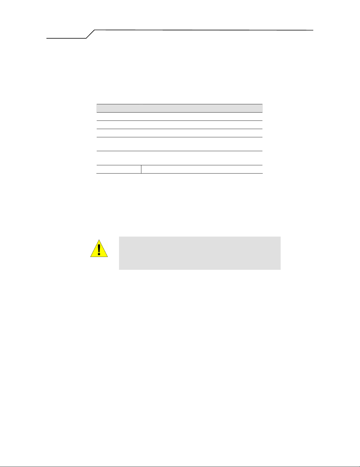
Before you begin, turn the power off for all devices. These include your
computer(s), your LAN hub/switch (if applicable), and the M404/M405.
WARNING
Step 1. Connect the ADSL cable and optional telephone
Connect one end of the phone cable to the RJ-11 connector on the rear panel of the M404/M405.
Connect the other end to the ADSL outlet provided by your service provider (normally MODEM
port of the included splitter).
Step 2. Connect the Ethernet cable
Connect one end of the Ethernet cable to the RJ-45 connectors on the rear panel of the M404/M405
and connect the other end to your PC’s network adaptor (NIC). If you are connecting a LAN to the
Master series, attach one end of the Ethernet cable to a regular hub port and the other end to the
LAN port on the M404/M405.
- 6 -
Page 7

Manual Ver1.0
Step 3. Attach the power connector
Connect the AC power adapter to the power connector on the M404/M405 and plug in the adapter
to a wall outlet or power extension.
Step 4. Turn on the M404/M405 and power up your systems
Press the Power switch on the back panel of the M404/M405 to the ON position.
Boot up your computer(s) and any LAN devices such as hubs or switches.
Step 5. Configure the M404/M405 through the WEB interface
Please refer to Chapter 3.
Step 6. Save the configurations and Reboot
Save the changes you made on the M404/M405 and it will automatically reboot to make the settings
permanent.
- 7 -
Page 8
Manual Ver1.0
3. Configuration
3.1 - Setup
Connect your M404/M405 and PC with an RJ-45 Ethernet cable.
Turn on the M404/M405.
The default IP address of M404/M405 is 192.168.1.254.
3.2 - Establish the Connection
Enter the IP address (default: 192.168.1.254) of M404/M405 in the address line of
your web browser.
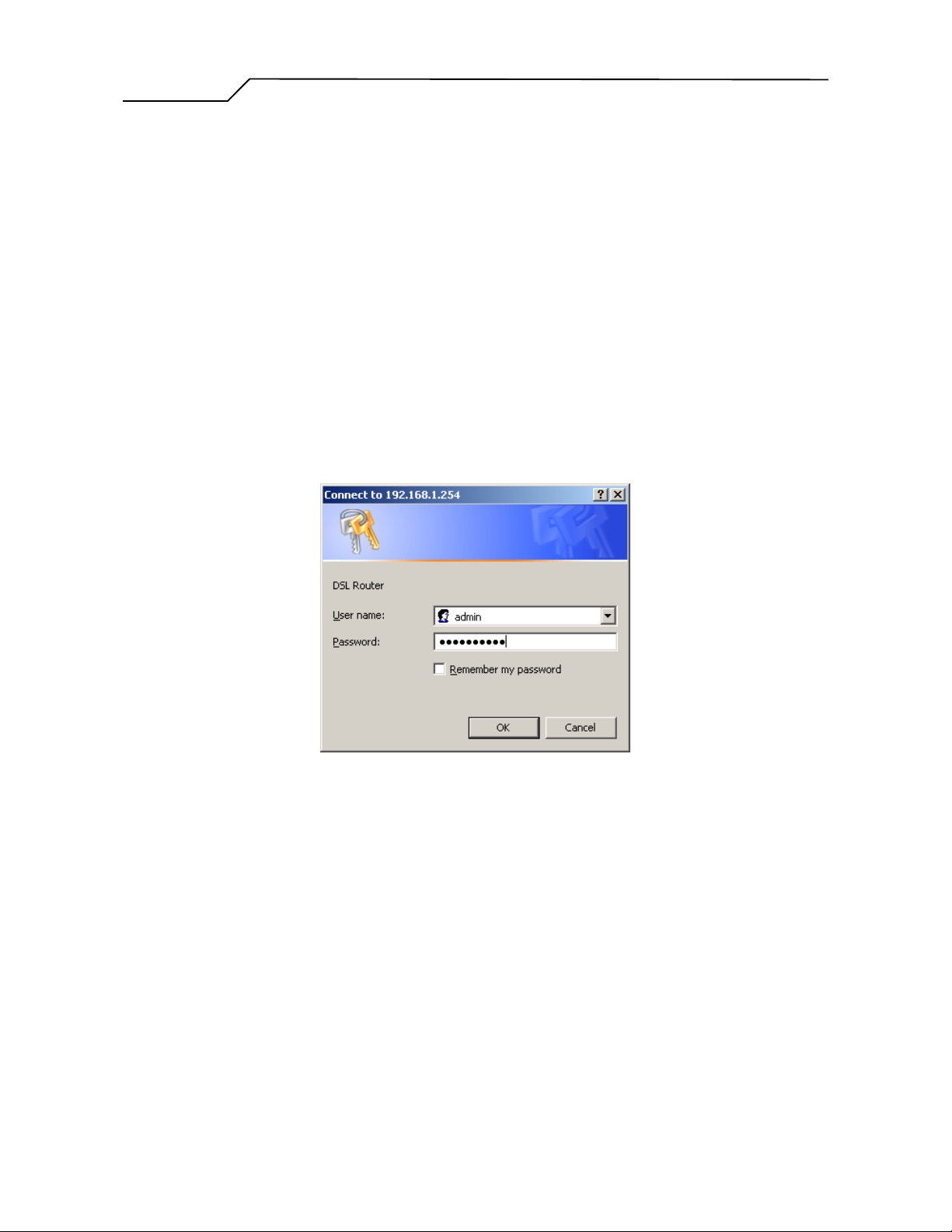
A Dialogue Box will pop up to request the user to login. (Figure 1)
Figure 1. Login dialogue box
Please enter the management username/password into the fields then click on the
OK button (Please contact your ISP for login information).
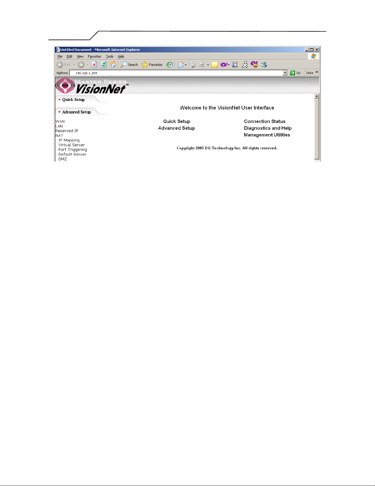
If the authentication is valid, the main page will be displayed on the screen.
(Figure 2)
- 8 -
Page 9
Manual Ver1.0
Figure 2. M404/M405 Home Page
- 9 -
Page 10
Manual Ver1.0
4. Quick Setup
The system administrator can configure the M404/M405 remotely or locally via a Web
Browser. Network configuration needs to be planned and decided before starting the
configuration procedure.
Quick Setup allows system administrator to select the appropriate operation mode and
configure the corresponding settings step by step to create a connection. The following
operation modes are supported under Quick Setup:
PPP over Ethernet (PPPoE)
PPP over ATM (PPPoA)
MER (MAC Encapsulation Routing)
IPoA (IP over ATM)
Bridging
4.1 - PPP over Ethernet (PPPoE) Configuration
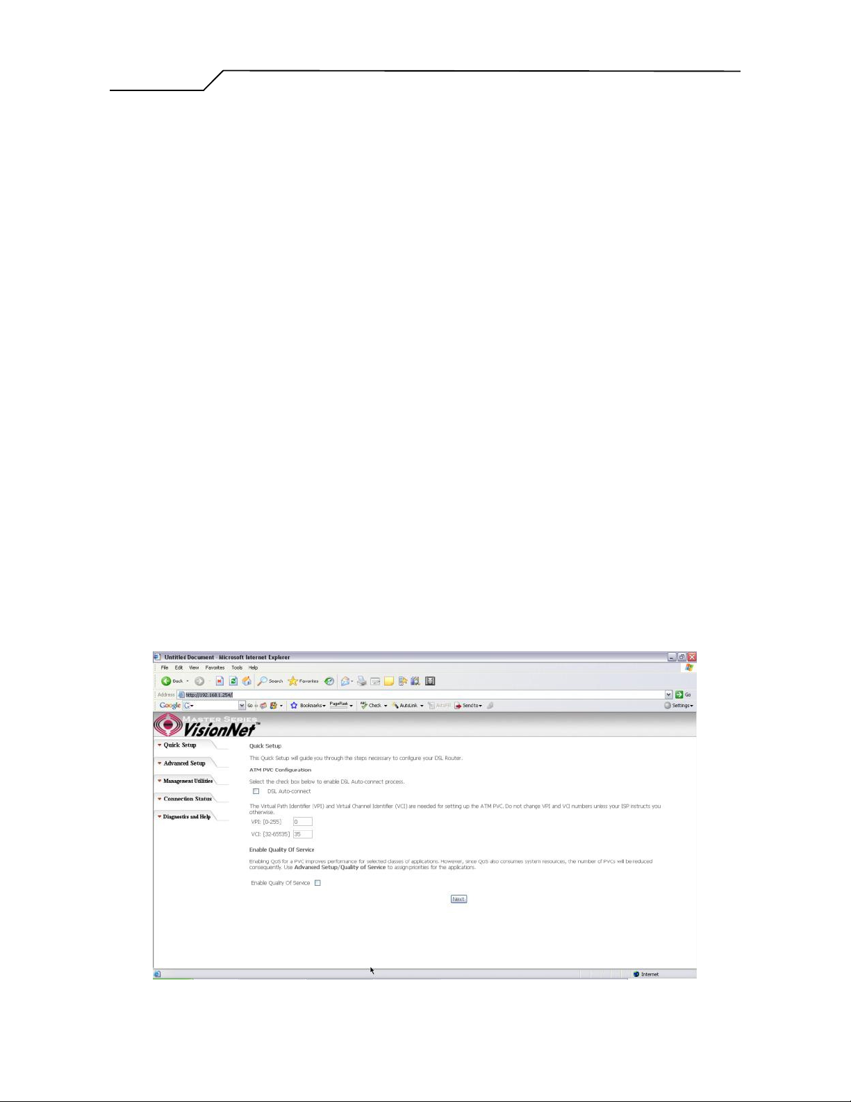
Click on “Quick Setup” in the left frame and follow the steps below to create a PPP
over Ethernet (PPPoE) connection.
Here you can either select DSL Autoconnect (Modem will attempt to find the correct
VPI/VCI settings) or Uncheck the box to manually input the VPI/VCI settings.
Figure 3. Quick Setup – ATM PVC
- 10 -
Page 11
Manual Ver1.0
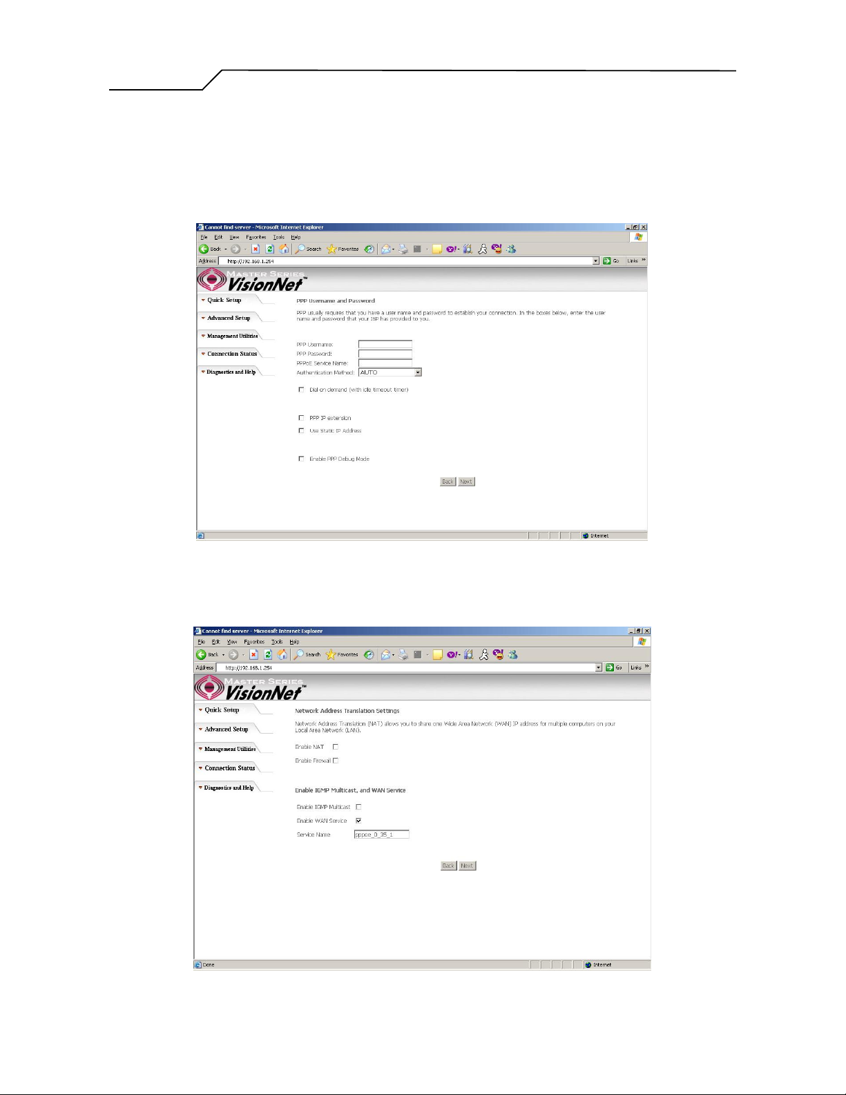
PPP Username and Password
This page is where you will enter the “PPP Username”, and “PPP Password”.
Please contact you ISP for this information.
Figure 4. Quick Setup – Username, Password and option forIP extension and Static IP
WAN Setup – NAT and IGMP
Figure 5. Quick Setup – WAN Setup – NAT, IGMP, and Firewall
- 11 -
Page 12
Manual Ver1.0
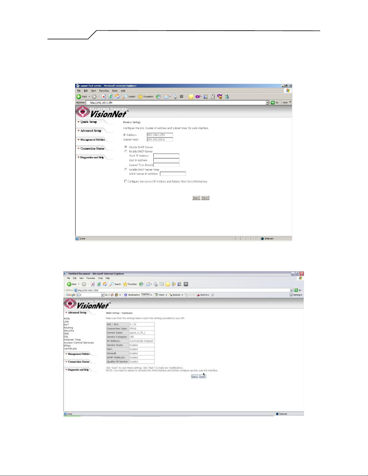
Device Setup
This page is where you can configure the modem’s IP address and Default DHCP
server range. Default is 192.168.1.254
Summary
Figure 6. Quick Setup – Device Setup – LAN and DHCP Server
Figure 7. Quick Setup – WAN Setup – Summary
- 12 -
Page 13
Manual Ver1.0
The last page displays a summary of your settings. Click on the “Save/Reboot”
button to complete the configuration.
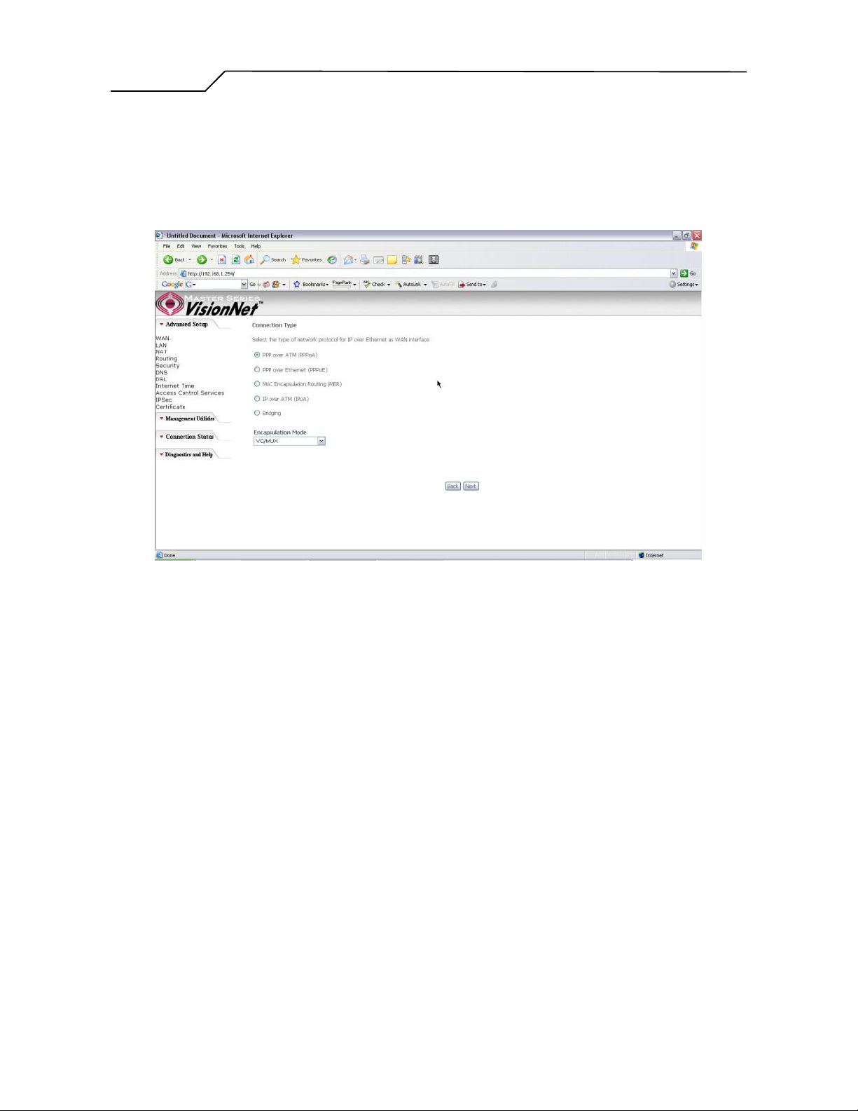
4.2 - PPP over ATM (PPPoA) Configuration
Configuration of PPPoA is similar to PPPoE. Select “PPP over ATM (PPPoA)” in
“Connection Type”. Please refer to PPPoE settings (Section 4.1) for details.
Figure 8. Quick Setup – Connection Type (PPPoA)
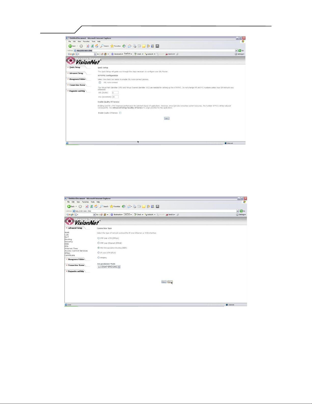
4.3 - MER (MAC Encapsulation Routing) Configuration
Click on “Quick Setup” in the left frame and follow the steps below to create a MER
connection.
Here you can either select DSL Autoconnect (Modem will attempt to find the correct
VPI/VCI settings) or Uncheck the box to manually input the VPI/VCI settings.
- 13 -
Page 14
Manual Ver1.0
Figure 9. Quick Setup – ATM PVC Configuration (MER)
Quick Setup – Connection Type
This page is where you select MER (MAC Encapsulation Routing).
Figure 10. Quick Setup – Connection Type
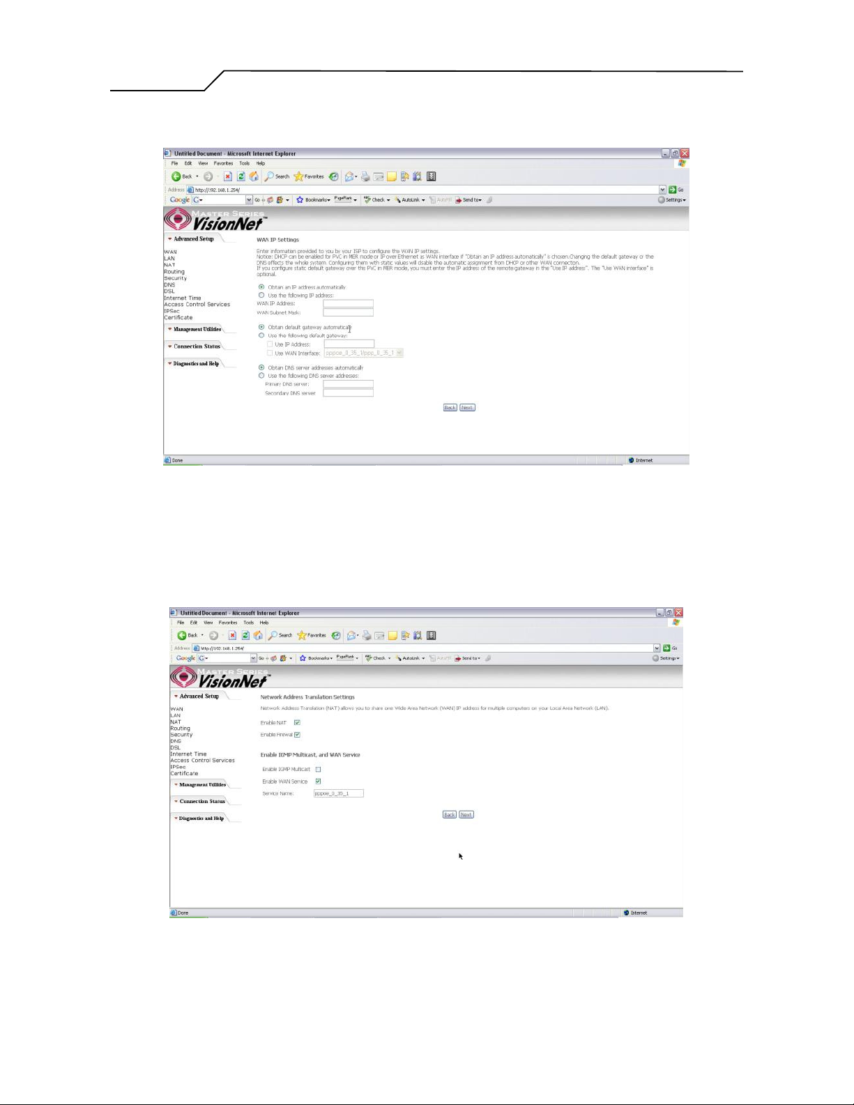
Quick Setup – WAN IP Settings
This page is where you either select for the M404/M405 to obtain the IP information
automatically (sometime referred to as DHCP connection) or you can input the IP
- 14 -
Page 15
Manual Ver1.0
address if Static IP’s were assigned by your Internet Service Provider.
Figure 11. Quick Setup – WAN IP Settings
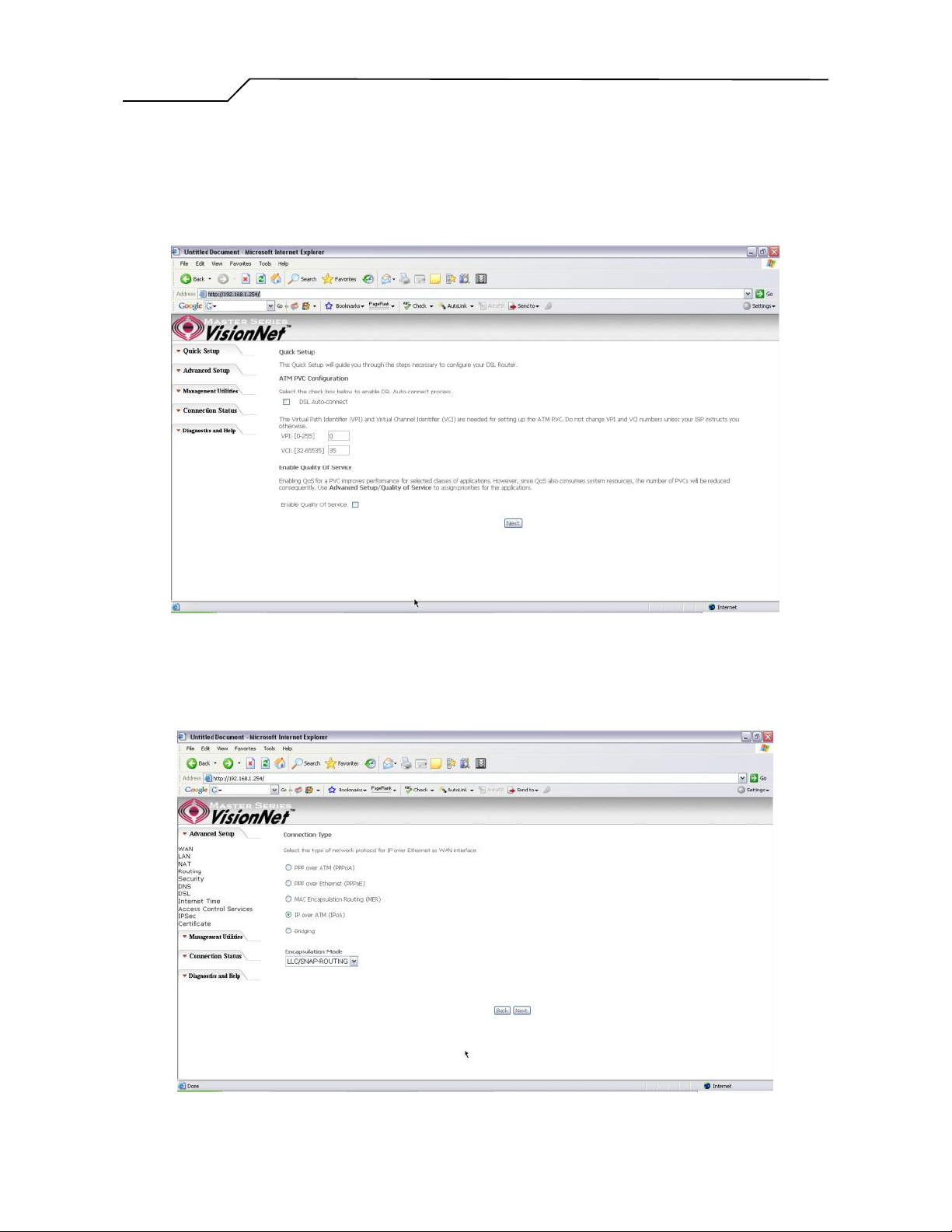
Quick Setup – Network Address Translation and IGMP
This page is where you either select to enable NAT (Please enable this option for the
M404/405 to route private (Local) IP address to your LAN clients).
Figure 12. Quick Setup – Network Address Translation and IGMP
- 15 -
Page 16

Manual Ver1.0
Quick Setup - Device Setup
This page is where you can configure the modem’s IP address and Default DHCP
server range. Default is 192.168.1.254
Figure 13. Quick Setup – Device Setup – LAN and DHCP Server
Quick Setup - Summary
Figure 14. Quick Setup – WAN Setup – Summary
The last page displays a summary of your settings. You must click on the “Save” button to complete
the configuration.
- 16 -
Page 17
Manual Ver1.0
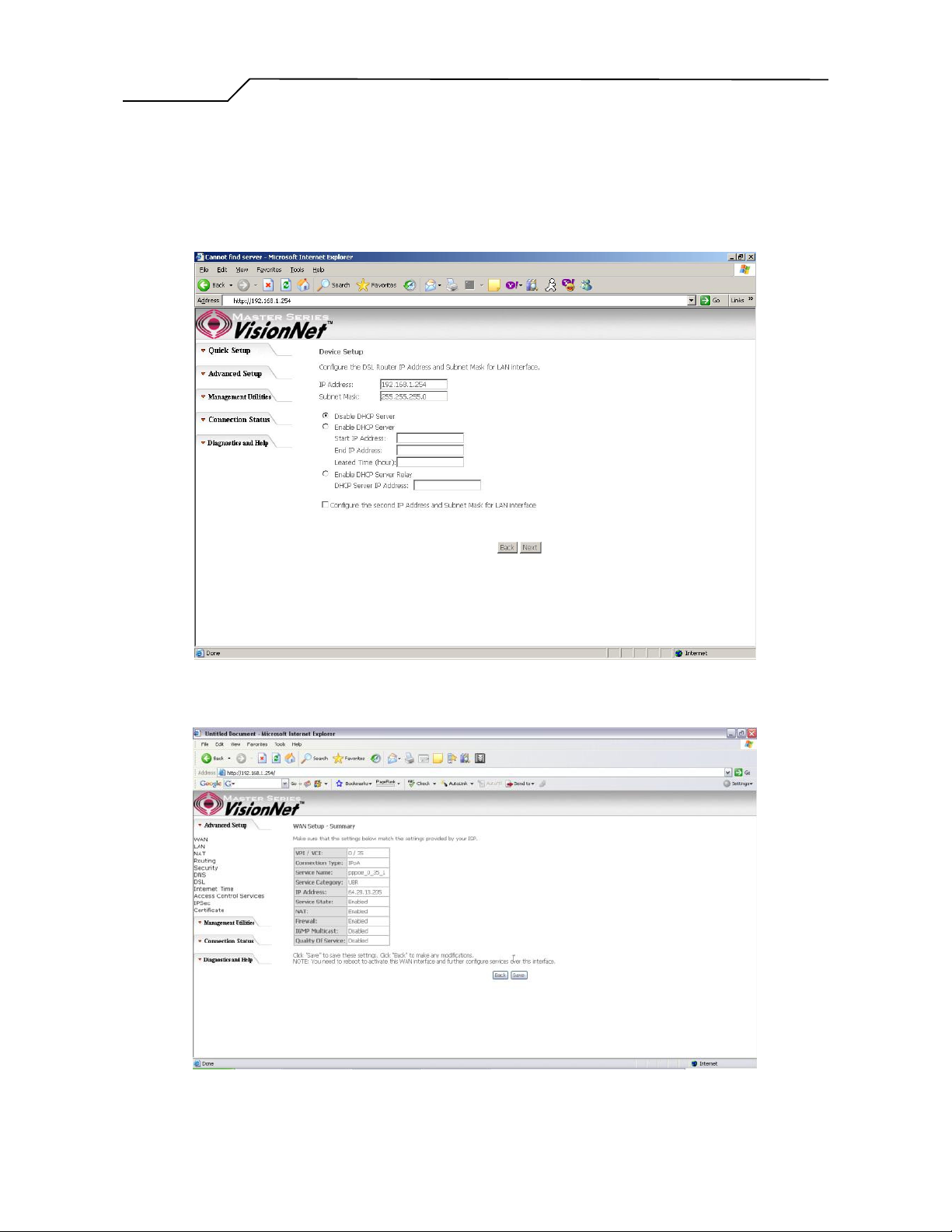
4.4 - IP over ATM (IPoA) Configuration
Click on “Quick Setup” in the left frame and follow the steps below to create an IPoA
connection.
Here you can either select DSL Autoconnect (Modem will attempt to find the correct
VPI/VCI settings) or Uncheck the box to manually input the VPI/VCI settings.
Quick Setup – Connection Type
This page is where you select IPoA (IP over ATM).
Figure 15. Quick Setup – ATM PVC
Figure 16. Quick Setup – Connection Type
- 17 -
Page 18

Manual Ver1.0
Quick Setup – WAN IP Settings
This page is where you input the IP information provided by your ISP. This
connection does not support DHCP (Where modem obtains IP information
automatically)
Figure 17. Quick Setup – WAN IP Settings
Quick Setup – Network Address Translation and IGMP
This page is where you either select to enable NAT (Please enable this option for the
M404/M405 to route private (Local) IP address to your LAN clients).
- 18 -
Page 19
Manual Ver1.0
Figure 18. Quick Setup – Network Address Translation and IGMP
Quick Setup - Device Setup
This page is where you can configure the modem’s IP address and Default DHCP
server range. Default is 192.168.1.254
Quick Setup – Summary
Figure 19. Quick Setup – Device Setup – LAN and DHCP Server
Figure 20. Quick Setup – WAN Setup – Summary
- 19 -
Page 20

Manual Ver1.0
The last page displays a summary of your settings. Click on the “Save” button to complete the
configuration.
4.5 - Bridging (Transparent/Pass-through) Configuration
Click on “Quick Setup” in the left frame and follow the steps below to create a Bridge
connection.
Here you can either select DSL Autoconnect (Modem will attempt to find the correct
VPI/VCI settings) or Uncheck the box to manually input the VPI/VCI settings.
Figure 21. Quick Setup – ATM PVC Configuration
Quick Setup – Connection Type
This page is where you select Bridging (Last option).
- 20 -
Page 21

Manual Ver1.0
Figure 22. Quick Setup – Connection Type
Quick Setup – Enabling Bridge Mode
For this page, please check the box “Enabled Bridge Service” and click “Next”
Figure 23. Quick Setup – Enabling Bridge Mode
- 21 -
Page 22

Manual Ver1.0
Quick Setup – Summary
Figure 24. Quick Setup – WAN Setup – Summary
The last page displays a summary of your settings. Please click the “Save” button to complete the
configuration process.
- 22 -
Page 23

Manual Ver1.0
5. Advanced Setup
Advanced Setup allows system administrator to configure the following topics:
WAN
LAN
NAT
Routing
Security
DNS
DSL
Internet Time
Access Control Services
IPSec
Certificates
5.1 - WAN
Figure 25. Advanced Setup – WAN
- 23 -
Page 24

Manual Ver1.0
5.2 - LAN
This page shows the current existing WAN interfaces in the system. User can choose
to Add, Edit, or Remove WAN interfaces. Clicking the “Add” button will take the user
to a wizard similar to the Quick Setup (Chapter 4) wizard, where additional WAN
protocols can be configured.
Protocols supported:
PPPoE, PPPoA, IP over ATM (IPoA), Bridging, MAC Encapsulation Routing
(MER).
Please refer to Section 4 for additional information regarding creating WAN
Connections.
Figure 26. LAN Setup page
Input the IP Address and Subnet Mask of your M404/M405.
(Default: 192.168.1.254)
Check the box if you want to enable UPnP and/or IGMP Snooping.
Disable/Enable DHCP Server, and change the starting and ending IP address of your
server pool if needed.
Check the “Configure the second IP Address and Subnet Mask for LAN interface” if a
second IP address is used.
- 24 -
Page 25

Manual Ver1.0
5.3 - NAT
Three functions are supported in NAT: Virtual Servers, Port Triggering, and DMZ Host.
Virtual Servers
Figure 27. Advanced Setup – NAT
Virtual Server allows you to direct incoming traffic from WAN side (identified by Protocol
and External port) to the Internal server with private IP address on the LAN side. The
Internal port is required only if the external port needs to be converted to a different port
number used by the server on the LAN side. A maximum of 32 entries can be configured.
Click on “Add” to enter configuration page to add your own rule(s). Some common used
servers (Web, FTP, Mail, …etc.) are already pre-defined for the M404/M405. User can
simply select the desired server from the pull-down menu and assign the IP address of the
local PC.
To delete the configured rule(s), check the “Remove” box of the specific rule(s) and click
on “Remove”.
- 25 -
Page 26

Manual Ver1.0
Port Triggering
Some applications require that specific ports in the Router's firewall be opened for access
by the remote parties. Port Trigger dynamically opens up the “Open Ports” in the firewall
when an application on the LAN initiates a TCP/UDP connection to a remote party using
the “Triggering Ports”. The Router allows the remote party from the WAN side to establish
new connections back to the application on the LAN side using the “Open Ports”. A
maximum of 32 entries can be configured.
Figure 28. Advanced Setup – NAT – Virtual Servers
- 26 -
Page 27

Manual Ver1.0
Figure 29. Advanced Setup – NAT – Port Triggering
Click on “Add” to enter the configuration page to add your own rule(s). Some games,
video conferencing, remote access applications and other software might require that
specific ports in the Router's firewall be opened for access. You can configure the port
settings from this screen by selecting an existing application or creating your own (Custom
application) and click “Save/Apply” to add it.
To delete the configured rule(s), check the “Remove” box of the specific rule(s) and click
on “Remove”.
- 27 -
Page 28

Manual Ver1.0
DMZ Host
The DSL router will forward IP packets from the WAN that do not belong to any of the
applications configured in the Virtual Servers table to the DMZ host computer.
Enter the computer's IP address and click “Save/Apply” to activate the DMZ host.
Clear the IP address field and click “Save/Apply” to deactivate the DMZ host.
Figure 30. Advanced Setup – NAT – Add Port Triggering
5.4 - Routing
There are three routing related settings:
Routing – Default Gateway
If the “Enable Automatic Assigned Default Gateway” checkbox is selected, the
M404/M405 will accept the first received default gateway assignment from one of the
PPPoA, PPPoE or MER/DHCP enabled PVC(s). If the checkbox is not selected, enter the
static default gateway AND/OR a WAN interface. Click the “Save/Apply” button to save it.
NOTE: If changing the “Enable Automatic Assigned Default Gateway” from
unselected to selected, you must reboot your M404/M405 to activate the
automatically assigned default gateway.
- 28 -
Figure 31. Advanced Setup – NAT – DMZ Host
Page 29

Manual Ver1.0
Figure 32. Advanced Setup – Routing – Default Gateway
Routing – Static Route
Click on “Add” to create a new Static Route. Up to 32 entries can be configured.
- 29 -
Page 30

Manual Ver1.0
Routing – RIP
Figure 33. Advanced Setup – Routing – Add New Static Route
Enter the destination network address, subnet mask, gateway AND/OR available WAN
interface, then click “Save/Apply” to add the entry to the routing table.
The Routing Information Protocol (RIP) is designed for exchanging routing information
within a small to medium-size network.
Figure 34. Advanced Setup – Routing – RIP
To configure an individual interface, select the desired RIP version and operation:
RIP Version 1: Class-based IP network.
RIP Version 2: Classless IP network.
Operation Active: Broadcast and listen to other RIP enabled devices.
Operation Passive: Listen only.
Place a check in the “Enabled” checkbox next to the interface to complete the
configuration. Click the “Save/Apply” button to save the configuration. To start/stop RIP
for the M404/M405, select the “Enabled/Disabled” radio button for “Global RIP Mode”.
- 30 -
Page 31

Manual Ver1.0
5.5 - Security
Two functions are supported in Firewall: Outgoing IP Filtering and MAC Filtering.
Firewall – Outgoing IP Filtering
By default, all outgoing IP traffic from LAN is allowed, but some IP traffic can be
BLOCKED by setting up filters. Choose “Add” to configure outgoing IP filters. To remove,
check the item and click “Remove”.
Figure 35. Advanced Setup – Security – Outgoing IP Filtering Setup
The screen allows you to create a filter rule to identify outgoing IP traffic by specifying a
filter name and at least one of the conditions below. All of the specified conditions in this
filter rule must be satisfied for the rule to take effect. Click “Save/Apply” to save and
activate the filter.
- 31 -
Page 32

Manual Ver1.0
Figure 36. Advanced Setup – Security – Add new Outgoing IP Filter
Security – WAN Access Control
WAN Access Control allows users to create time of day restrictions to a specific LAN
device connected to the Router. Click “Add” to configure restriction rules. To remove,
check the item and click “Remove”. Up to 16 entries can be configured and used.
- 32 -
Page 33

Manual Ver1.0
Figure 37. Advanced Setup – Security – WAN Access Control
The MAC Address of the current “browser” will automatically display on the “Browser’s
MAC Address” box. To restrict another LAN device, click the “Other MAC Address”
button and enter the MAC address of that LAN device.
To find out the MAC address of a Windows-based PC, go to the command prompt window
and type “ipconfig /all”. Click “Save/Apply” to save and activate the restriction rule.
- 33 -
Page 34

Manual Ver1.0
5.6 - DNS
DNS Server
Figure 38. Advanced Setup – Security – Add new Parental Control restriction
- 34 -
Page 35

Manual Ver1.0
If “Enable Automatic Assigned DNS” checkbox is selected, the M404/M405 will accept
the first received DNS assignment from one of the PPPoA, PPPoE or MER/DHCP enabled
PVC(s) during the connection establishment. If the checkbox is not selected, enter the
primary and optional secondary DNS server IP addresses. Click the “Save” button to save
it.
NOTE: If changing from unselected “Enable Automatic Assigned DNS” to selected, you
must reboot the M404/M405 to get the automatic assigned DNS addresses.
Dynamic DNS
The Dynamic DNS service allows you to give a dynamic IP address a static hostname in
any of the domains. This function allows your M404/M405 to be more easily accessible
from various locations of the Internet.
Choose “Add” to configure Dynamic DNS.
Figure 39. Advanced Setup – DNS Server
Before you proceed, please visit one of these two websites to receive your own Dynamic
DNS service: www.dyndns.org or www.tzo.com.
To remove, check the item and click “Remove”
Figure 40. Advanced Setup – DNS – Dynamic DNS
- 35 -
Page 36

Manual Ver1.0
Select your Dynamic DNS service provider from ‘D-DNS provider’, and enter your
registration information. Click “Save/Apply” to save the configuration.
Figure 41. Advanced Setup – DNS – Add Dynamic DNS
- 36 -
Page 37

Manual Ver1.0
5.7 - DSL
This page allows you to choose which handshake protocols you want your M404/M405 to
look through when training. Uncheck any of the listed protocols that have “Enabled” at the
end of it to have the modem skip that protocol when synchronizing with your ADSL line.
Leave it checked if you would like the modem to cycle through those settings.
Figure 42. Advanced Setup – DSL Settings
.
- 37 -
Page 38

Manual Ver1.0
5.8 - Internet Time
The M404/M405 can synchronize its internal time with an Internet time server when
available. To enable this function, check “Automatically synchronize with Internet time
servers”. Select First and Second NTP time server from the pull down menu. Or select
“Other” and define your preferred NTP server. Choose the time zone from “Time zone
offset”. Click on “Save/Apply” to save the configuration.
Figure 43. Advanced Setup - Internet Time
5.9 - Access Control Services
Services
The M404/M405 browser management tool is protected by three categories: Services, IP
addresses, and Passwords. All three must be matched (if configured) to gain access to the
management tool.
All services are enabled from LAN side and disabled from WAN side by default.
- 38 -
Page 39

Manual Ver1.0
Figure 44. Advanced Setup - Access Control - Service
IP Addresses
The IP Address Access Control mode, if enabled, permits access to local management
services from IP addresses contained in the Access Control List. If the Access Control
mode is disabled, the system will not validate IP addresses for incoming packets. The
services are the system applications listed in the Service Control List.
Click “Add” to add an IP address to the Access Control List. To remove, mark the Remove
option of the specified IP address, then click “Remove” to remove the IP address from the
Access Control List. Up to 16 hosts can be configured here.
- 39 -
Page 40

Manual Ver1.0
Figure 45. Advanced Setup - Access Control – IP Addresses
Passwords
Access to your router is controlled through three user accounts: admin, support, and user.
admin: has unrestricted access to change and view the M404/M405 configuration.
support: is used to allow an ISP technician to access the M404/M405 for maintenance and to
run diagnostics.
user: can access the M404/M405 to view configuration settings and statistics, as well as,
update the M404/M405 software.
Use the fields below to enter up to 16 characters and click “Save/Apply” to change or
create passwords.
- 40 -
Page 41

Manual Ver1.0
5.10 - IPSec
The M404/M405 also has the ability to create a VPN (Virtual Private Network) tunnel
using IPSec as the security measure. VPN allows user to remotely connect to a network
using their Broadband connection. Please refer to your ISP and Network Administrator for
detail settings regarding VPN IPSec.
Figure 46. Advanced Setup - Access Control – Passwords
Figure 47. Advanced Setup – IPSec
- 41 -
Page 42

Manual Ver1.0
Click the “Add” button create a new VPN connection
Figure 48. Advanced Setup – IPSec Add
5.11 - Certificate
This page allows user to authenticate their VPN session using certificate. Some VPN
network requires this. There are two sections: Local and Trusted CA.
LOCAL option: A maximum of 4 certificates are supported. You can either import or send a
request for certificates.
- 42 -
Page 43

Manual Ver1.0
Figure 49. Advanced Setup - Certificates
Figure 50. Advanced Setup – Local – Create Certificate
Figure 51. Advance Setup – Certificates – Local Import
Trusted CA option: This is used to verify peer certificates. Please click on “Import
Certificate” to proceed.
- 43 -
Page 44

Manual Ver1.0
Figure 52. Advanced Setup – Certificates- Trusted CA
Figure 53. Advanced Setup – Certificates - Trusted CA – Import Certificate
- 44 -
Page 45

Manual Ver1.0
6. Management Utilities
6.1 - Backup Settings
System Administrator can do the M404/M405 settings backup, update, and restore default
here. The settings can be saved from M404/M405 to PC. The saved setting file can also be
loaded from PC to M404/M405. These 2 functions can help the system administrator to
manage large amount of M404/M405 efficiently. Restore Default would set the
M404/M405 with the factory default configuration.
To backup the current configurations, click on “Backup Settings”, and a File Download
window will pop up.
Figure 54. Management Utilities – Backup Settings
Click on “Save” and select the destination of the backup file (backupsettings.cfg) in your
local PC. Click on “Save” again to save your backup file.
- 45 -
Page 46

Manual Ver1.0
Figure 55. Management Utilities – Backup Settings – File Download
6.2 - Update Backup Settings
To update the configuration, click on “Browse” and a Choose-File-window will pop up.
Locate the saved file and click on “Update Backup Settings”. The M404/M405 will modify
its settings based on the update file.
Figure 56. Management Utilities – Update Settings
- 46 -
Page 47

Manual Ver1.0
6.3 - Restore Settings
To restore the router to its factory default settings, click on “Restore Default Settings”.
Figure 57. Management Utilities– Restore Default Settings
6.4 - Update Firmware
The new software could be updated from the Local PC connected to M404/M405 via
Ethernet cable. Click on “Browse” to locate the new software image file in the PC. And
then Click on “Update Software” to proceed with the software update.
Note: The update process takes about 2 minutes to complete, and your M404/M405 will
reboot
automatically.
- 47 -
Page 48

Manual Ver1.0
Figure 58. Management Utilities – Update Software
6.5 - TR069 Server
This feature allows your Internet Service Provider’s ACS (Auto Configuration Server) to
provision your M404/M405 remotely. Actions such as configuring the modem settings,
diagnostic, and collecting data can be accomplish with this feature. The information for the
settings to be entered in the fields must be provided by your Internet Service Provider.
Figure 59. Management Utilities – TR069 Server
- 48 -
Page 49

Manual Ver1.0
6.6 - Save/Reboot
Click “Reboot Router” to reboot M404/M405. The M404/M405 would automatically save
the configuration before reboot, so that modified settings would take effect after reboot.
6.7 - System Log
This allows System Administrator to view the System Log and configure the System Log
options.
- 49 -
Figure 60. Management Utilities – Save / Reboot
Page 50

Manual Ver1.0
Figure 61. Management Utilities – System Log
Click on “Configure System Log” to configure the log options. There are 8 events of “Log
Level” and “Display Level”: Emergency, Alert, Critical, Error, Warning, Notice,
Informational, and Debugging. If the log mode is enabled, the system will begin to log all
the selected events. For the Log Level, all events above or equal to the selected level will
be logged. For the Display Level, all logged events above or equal to the selected level will
be displayed.
If the selected mode is “Remote” or “Both”, events will be sent to the specified IP address
and UDP port of the remote syslog server. If the selected mode is “Local” or “Both”,
events will be recorded in the local memory. Click on “Save/Apply” to save the
configuration.
- 50 -
Page 51

Manual Ver1.0
Figure 62. Management Utilities – System Log Configuration
Click on “View System Log” to see the router log based on your configuration
- 51 -
Page 52

Manual Ver1.0
7. Connection Status
7.1 - LAN
This page displays the status of packets transmitted and received on the M404/M405 LAN
interfaces.
7.2 - WAN
The WAN Connection Status is broken into 2 parts:
Figure 63. Connection Status – LAN
1. Connection – Information concerning the WAN protocol currently in used by the
M404/M405 to connect to the Internet. In the figure below: The modem is
currently in PPPoE mode, IGMP option is disabled, No Quality of Service is used,
the PPPoE connection is Up and the WAN IP address that the modem receives
from the Internet Service Provider Equipment.
2. Status –Information concerning Packets Received and Transmitted on the WAN
side based on the Protocol used by the M404/M405 (example shows PPPoE
connection).
- 52 -
Page 53

Manual Ver1.0
Figure 64. Connection Status – WAN Connection
Figure 65. Connection Status – WAN Status
- 53 -
Page 54

Manual Ver1.0
7.3 - ATM
This page displays the statistics of M404/M405 ATM interface (including AAL5).
7.4 - ADSL
This page displays the M404/M405 ADSL connection information and status, such as Rate
(Kbps), SNR, ES (Error Second)…etc. This information is useful when there are problems
with your ADSL connection (The M404/M405 DSL LED light does not stay solid for
example)
Figure 66. Connection Status – ATM
- 54 -
Page 55

Manual Ver1.0
7.5 - Route
This page displays the M404/M405 routing table.
Figure 67. Connection Status – ADSL
- 55 -
Page 56

Manual Ver1.0
Figure 68. Connection Status – Route
7.6 - ARP (Address Resolution Protocol)
This page displays the M404/M405 ARP table.
Figure 69. Connection Status – ARP
7.7 - DHCP
This page displays the lease time for PC’s or devices connected to the router
- 56 -
Page 57

Manual Ver1.0
7.8 - Summary
This page displays the summary of the M404/M405 hardware, software and connection
information. Line Rate shows the speed that you are currently connected to your ISP. In the
figure below the M404/405 is currently connected at a Download speed of 3000 Kbps or 3
Mbps with an Upload speed of 512 Kbps or 0.5 Mbps. MAC address and LAN IP address
of the M404/M405. Gateway and DNS information is also shown.
Figure 70. Connection Status - DHCP
Figure 71. Connection Status - Summary
- 57 -
Page 58

Manual Ver1.0
8. Diagnostics and Help
This page allows users to test the Ethernet port connection, DSL port connection, and
connection to the Internet Service Provider. If a test displays a fail status, click “Return
Diagnostic Tests” at the bottom of the page to make sure the fail status is consistent. If the
test continues to show fail, click “Help” to go to through the troubleshooting procedures.
Figure 72. Diagnostics and Help
- 58 -
Page 59

Manual Ver1.0
9. Appendix A – Specifications
A1. Hardware Specifications
Local Interface
• One 10/100BaseT Ethernet port (IEEE 802.3, RJ-45 connector)
• One USB 1.1 port (M405)
WAN ADSL Line Interface
• Complies with G.dmt (G.992.1) Annex A
• Complies with G.lite (G.992.2) and T1.413
• Complies with ADSL2 (G.992.3)
• Complies with ADSL2+ (G.992.5)
• Connector: RJ-11
OAM&P
• Remote: Telnet or Web browser
Environment
• Operation Temperature: 0°C ~ 40°C
• Operation Humidity: 10% ~ 95%
• Storage Temperature: -20 ~ 70°C
• Storage Humidity: 5%~95%
Power
• AC Adapter :Input 120V AC 60Hz; Output 10VDC 1A
Certificates
• FCC Part 68 and 15 Class B, UL
A2. Software Specifications
ATM
• ATM Cell over ADSL, AAL5
• Supports UBR, CBR & VBR-nrt
• VPI Range (0-255) and VCI range (1-65535)
• Supports up to 8 PVCs
• Supports OAM F4/F5, and loop back cells
• Payload Encapsulation --
− RFC2684 (RFC1483), multi-protocol over ATM
− RFC2364, PPP over ATM (CHAP and PAP supported)
− RFC2516, PPPoE (PPP over Ethernet) over ATM
Bridging
• Transparent Bridging (IEEE 802.1D)
• RFC2684 (RFC1483) Bridged
• Spanning Tree Protocol (IEEE 802.1D)
• Bridge Filtering
Routing
• IP Address Forwarding
• MAC Encapsulated Routing
• Routing Information Protocol (RIP) v1, v2
DHCP Client (to the DSL network)
•
DHCP relay agent
•
• NAT/PAT – RFC1631 (basic Firewall support)
• Support Point-to-Point Protocol (PPP)
• PAP for user authentication
• RFC2684 (RFC1483) Routed
- 59 -
Page 60

Manual Ver1.0
• DNS relay
• UPnP
• IGMP-Proxy
Configuration and Network Management
• DHCP server for IP management
• HTTP (Web Server) for configuration and firmware upgrade
• TFTP Server
• FTP Server
Firewall
• NAT ALGs
• IPSEC pass-through
• Ping of Death
• SYN Flood LAND
• Protection against IP and MAC address spoofing
• Packet Filtering
• Stateful Packet Inspection (SPI)
• UPnP NAT Traversal
- 60 -
Page 61

Manual Ver1.0
10. Appendix B – Warranties
DQ Technology adheres to the strictest Quality Assurance processes to ensure that our products are free from defects prior to
shipping. DQ Technology provides a standard 1 year limited warranty for all products and provides an extended warranty option for
North American customers.
Please note that standard warranty terms apply to all equipment sold by DQ Technology unless an extended warranty has been
purchased.
The 1 year limited warranty offered by DQ Technology Inc. is non-transferrable. End Users who purchased equipment from a
Service Provider, or other source, should contact the company from whom they purchased the equipment for all warranty and returns.
This warranty is not transferable and does not include service, repair, or replacement to correct any damage caused by improper
installation or maintenance, improper connection with any peripheral, external electrical fault, accident, disaster, misuse, abuse, or
modifications to the DSL modem not approved in writing by DQ Technology. All implied warranties are hereby limited to a One
(1) year term. DQ Technology hereby disclaims all express warranties not included in these terms.
DQ Technology warrants that all products are free from defective material and workmanship and, subject to the conditions set forth
below, agrees to repair or replace any part of a product, which proves defective by reason of improper workmanship or materials
without charge for parts and labor.
If a Product does not perform as warranted herein, owner's sole remedy shall be repair or replacement as provided below. In no
event will DQ Technology be liable for damages, lost revenue, lost wages, lost savings, or any other incidental or consequential
damages arising from purchase, use, or inability to use this product, even if DQ Technology has been advised of the possibility of
such damages. Any defective Product should be returned to the address above unless otherwise instructed by this notice, along with
a copy of your sales slip, the product serial number (if applicable), and a detailed description of the problem(s) you are experiencing.
No express or implied warranty is made for DQ Technology Products damaged by accident of use, misuse, natural or personal
disaster or any unauthorized disassembly, repair or modification.
DQ Technology's Warranty covers only repair or replacement of defective Products
DQ Technology is not liable for, and does not cover under Warranty, any costs associated with servicing or installation of Products.
If you experience any difficulty during installation or subsequent use of Products, please contact Technical Support at
1-866-286-XDSL or email [email protected].
DQ Technology warrants that all solid-state memory products are free from defect in material and workmanship. Subject to the
conditions and limitations set forth below, DQ Technology will repair or replace any part of a Product that proves defective by
reason of improper workmanship or materials.
Repair parts or replacement Products will be furnished on an exchange basis and will be either new or refurbished to be functionally
equivalent to new.
- 61 -
Page 62

Manual Ver1.0
Appendix C – Regulations
C1. FCC Part 15 Notice
Warning: This equipment has been tested and found to comply with the limits for a Class B digital device, pursuant to
Part 15 to the FCC rules. These limits are designed to provide reasonable protection against harmful interference when
the equipment is operated in a residential environment. This equipment generates, uses, and can radiate radio frequency
energy, and, if not installed and used in accordance with the instruction manual, may cause harmful interference to radio
communications. Operation of this equipment in a residential area is unlikely to cause harmful interference. But if it
does, the user will be required to correct the interference at his or her own expense. The authority to operate this
equipment is conditioned by the requirement that no modifications will be made to the equipment unless DQ
Technology expressly approves the changes or modifications.
C2. UL Safety Regulations
Disconnect TNV circuit connector or before removing cover or equivalent.
Disconnect TNV circuit connector(s) before disconnecting power.
Do not use this product near water for example, near a bathtub, washbowl, and kitchen sink or laundry tub, in a wet
basement, or near a swimming pool.
Avoid using a telephone (other than a cordless type) during an electrical storm. There may be a remote risk of
electric shock from lightening.
Do not use the telephone to report a gas leak in the vicinity of the leak.
Use only the power cord batteries indicated in this manual. Do not dispose of batteries in a fire, as they may
explode. Check with local codes for possible special disposal instructions.
No. 26 AWG Telephone Line Cord shall either be provided with the equipment or shall be described in the safety
instruction. If fuse (F1) is not present, see the caution statement listed below:
CAUTION: To reduce the risk of fire, use only No. 26 AWG or larger UL
Listed or CSA Certified Telecommunication Line Cord.
- 62 -
Page 63

Manual Ver1.0
Contact Information
You can help us to serve you better by sending us your comments and feedback. Listed below are the addresses, and
telephone and fax numbers of our offices. You can also visit us on the World Wide Web at
information. We look forward to hearing from you!
World Headquarters
5111 Johnson Dr.
Pleasanton, CA 94588
Tel: (925) 730-3940 Fax: (925) 730-3950
Technical Support
(866) 286-xDSL (9375)
www.dqusa.com for more
- 63 -
 Loading...