

Page 1
Page 2

Strand Lighting - Dallas
10911 Petal Street
Dallas, TX 75238
Tel: 214-647-7880
Fax: 214-647-8031
Strand Selecon - Auckland
19-21 Kawana Street
Northcote, Auckland 0627
New Zealand
Tel: +64 9 481 0100
Fax: +64 9 481 0101
Strand Lighting - New York
267 5th Ave, 4th Floor
New York, NY 10016
Tel: 212-213-8219
Fax: 212-532-2593
Strand Lighting - Europe
Marssteden 152
Enschede 7547 TD
The Netherlands
Tel: +31 53 4500424
Strand Lighting - Asia Limited
Fax: +31 53 4500425
Room 6-10, 20/F Delta House 3 On Yiu Street
Shatin, N.T. Hong Kong
Tel: + 852 2757 3033
Fax: + 852 2757 1767
www.strandlighting.com
Website:
The material in this manual is for information purposes only and is subject to change without notice.
Strand Lighting assumes no responsibility for any errors or omissions which may appear in this manual.
For comments and suggestions regarding corrections and/or updates to this manual, please contact your
nearest Strand Lighting office.
El contenido de este manual es solamente para información y está sujeto a cambios sin previo aviso.
Strand Lighting no asume responsabilidad por errores o omisiones que puedan aparecer. Cualquier
comentario, sugerencia o corrección con respecto a este manual, favor de dirijirlo a la oficina de Strand
Lighting más cercana.
Der Inhalt dieses Handbuches ist nur für Informationszwecke gedacht, Aenderungen sind vorbehalten.
Strand Lighting uebernimmt keine Verantwortung für Fehler oder Irrtuemer, die in diesem Handbuch
auftreten. Für Bemerkungen und Verbesserungsvorschlaege oder Vorschlaege in Bezug auf Korrekturen
und/oder Aktualisierungen in diesem Handbuch, moechten wir Sie bitten, Kontakt mit der naechsten
Strand Lighting-Niederlassung aufzunehmen.
Le matériel décrit dans ce manuel est pour information seulement et est sujet à changements sans préavis.
La compagnie Strand Lighting n'assume aucune responsibilité sur toute erreur ou ommission inscrite dans
ce manuel. Pour tous commentaires ou suggestions concernant des corrections et/ou les mises à jour de ce
manuel, veuillez s'll vous plait contacter le bureau de Strand Lighting le plus proche.
Information contained in this document may not be duplicated in full or in part by any person without
prior written approval of Strand Lighting. Its sole purpose is to provide the user with conceptual
information on the equipment mentioned. The use of this document for all other purposes is specifically
prohibited.
Vision.net Station Installation & Operation Guide
Document Number: 2-450223-010
Version as of: October 14, 2010
©2010 Philips Group. All rights reserved.
Page 3
Vision.net Control Station Installation & Operation Guide
Important Safeguards
When using electrical equipment, basic safety precautions should always be followed
including the following:
a. READ AND FOLLOW ALL SAFETY INSTRUCTIONS.
b. Do not use outdoors.
c. Do not mount near gas or electric heaters.
d. The use of accessory equipment not recommended by the manufacturer
may cause an unsafe condition.
e. Do not use this equipment for other than intended use.
f. Refer service to qualified personnel.
SAVE THESE INSTRUCTIONS.
WARNING: You must have access to a main circuit breaker or other power
disconnect device before installing any wiring. Be sure that power is disconnected
by removing fuses or turning the main circuit breaker off before installation.
Installing the device with power on may expose you to dangerous voltage and
damage the device. A qualified electrician must perform this installation.
WARNING: Refer to National Electrical Code® and local codes for cable
specifications. Failure to use proper cable can result in damage to equipment or
danger to persons.
CAUTION: Wire openings MUST have fittings or lining to protect wires/cables
from damage.
1
Page 4

Installation & Operation Guide Vision.net Control Station
TABLE OF CONTENTS
Preface ....................................................................................................................................... 3
About this Guide ............................................................................................................... 3
Vision.net System Overview............................................................................................. 3
Quick Start ................................................................................................................................ 4
Installation ................................................................................................................................. 5
Overview........................................................................................................................... 5
Installation Steps ............................................................................................................... 6
Replacing Standard Buttons with Engraved Buttons ........................................................ 6
Vision.net Station Operation Modes ......................................................................................... 8
Overview........................................................................................................................... 8
Standard Mode .................................................................................................................. 8
Configurable Mode ........................................................................................................... 8
Operation........................................................................................................................... 9
Programming..................................................................................................................... 9
Troubleshooting ........................................................................................................................ 9
Network Test Signal.......................................................................................................... 9
Button Station Faceplate Alignment ................................................................................. 9
2
Page 5

Vision.net Control Station Installation & Operation Guide
PREFACE
About this Guide
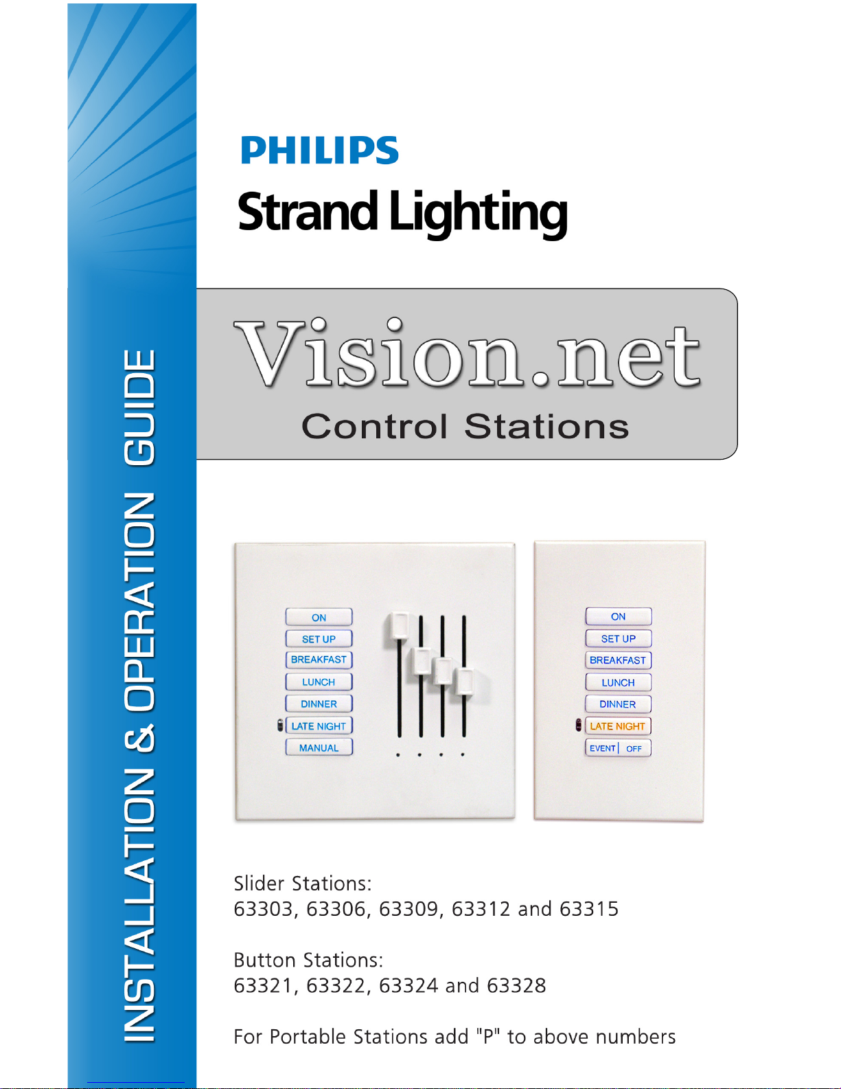
The document provides installation instructions for the following Vision.net products:
• Slider Stations: 63303, 63306, 63309, 63312 and 63315
• Button Stations: 63321, 63322, 63324 and 63328
• Portable Stations: Any of the above models with a "P" added to the end of the part
number (for example, 63303P).
Please read all instructions before installing or using these products. Retain this guide for
future reference.
For Vision.net Station configuration instructions, please download the Vision.net Designer
software and its accompanying manual from www.strandlighting.com.
IMPORTANT INFORMATION. PLEASE READ!
This unit is intended for installation in accordance with the National Electric Code® and local
regulations. It is also intended for permanent installation in indoor applications only. Before
any electrical work is performed, disconnect power at the circuit breaker or remove the fuse to
avoid shock or damage to the control. It is recommended that a qualified electrician perform
this installation.
Vision.net System Overview
The Vision.net system is designed to control architectural lighting by distributing both power
and intelligence. The system provides processing power and control at each respective station,
eliminating the need for a central processor.
Vision.net stations provide individual control of up to 16 sliders or up to 35 buttons per station.
Combinations of sliders and buttons can be configured as well. A single gang faceplate can
have up to 8 buttons or 3 sliders (with a Grand Master). For more buttons or sliders, just
expand the faceplate from a single gang up to a five gang faceplate.
Multiple stations may be linked together for control of up to 127 sliders.
Vision.net products are controlled by the Vision.net System protocol. All Vision.net control
devices must be connected to the Vision.net system and given a unique ID (or address) in
order to interact properly. The ID identifies the device on the network and allows the device to
avoid network collisions when transmitting data.
3
Page 6

Installation & Operation Guide Vision.net Control Station
QUICK START
This section is designed for experienced technicians in order to get a standard Vision.net
Station up and running quickly.
Use the following checklist:
Step 1. Install unit (refer to "Installation" on page 5).
Step 2. Connect to Vision.net network (refer to Figure 4 on page 7).
Step 3. Set mode using Vision.net Designer software.
The unit should now be ready for operation.
Note: Stations are pre-configured at the factory with a Station ID of 1 and are set to activate
Presets 1 to 7 in Room 1 of your Vision.net system.
The drawing below shows an example of a 3-gang station which is made up of one (1) button
station and two (2) slider stations:
Refer to Figure 4 on page 7 for example wiring diagrams.
4
Figure 1: Example 3-Gang Station
Page 7

Vision.net Control Station Installation & Operation Guide
INSTALLATION
This section provides installation instructions for all Vision.net button/slider stations.
Overview
Electrical Specifications:
• Input Power: +18-26 VDC (powered from Vision.net
network)
• Current: 20mA
• Temperature:
- Storage: -25° to 85° C
- Operating: 0° to 40° C
- Relative Humidity: 30-90% (non-condensing)
Communications:
• Strand Vision.net protocol (SVN/485)
1
2
3
4
5
6
7 8
• Vision.net 4-Wire Digital LAN
• Contact Closure
Figure 2: 8-Button Station
Network Wiring:
The Vision.net network consists of a single CAT5e cable connecting all modules in a daisychain manner. All units connect to the network using a 9-pin plug-in connector (included).
LED Indications:
There are three (3) LEDs on the Control PCB. The following is a description of each LED’s
status when flashing:
• RED - Will blink whenever there is any activity from the front buttons or slider modules.
• GREEN - Will blink whenever the unit receives or transmits network SVN/485 traffic.
• AMBER - Will blink whenever the unit receives or transmits sensor 4-wire digital LAN
traffic.
Note: Since button or slider activity will sometimes result in transmissions, it may appear to
be a transmit status, but it is not (try moving a slider when not in Manual Mode).
Note: Not all button or slider activity will result in network traffic. For example, moving a
slider while not in Manual Mode will not generate LED activity from traffic.
5
Page 8

Installation & Operation Guide Vision.net Control Station
Installation Steps
To install slider/button stations:
Step 1. Unpack unit and inspect for
any signs of shipping
damage.
Step 2. If this is a slider station,
remove slider knobs by
pulling off (Figure 3).
Step 3. Remove faceplate by pulling
on the top.
Step 4. To replace standard keypad
with custom (if required):
a. Remove keypad retainer
by inserting a small (flat)
screwdriver in slots and
prying up.
b. Lift retainer off and
remove keypad. Install
new keypad and snap
retainer back in place.
Remove knobs
by pulling off
Step 2.
Remove
faceplate by
pulling on top
Step 3.
Small (Flat) Screwdriver
Pry slots
Keypad
Retainer
Step 5. At station’s back panel,
connect Vision.net Network
Cable to 9-pin connector.
(Refer to Figure 4 on next
page.)
Step 6. Connect Occupancy/
Photocell Sensors and
Contact Closures (if
required) to 6-pin connector.
Step 7. Attach station to backbox
using the screws supplied
with the backbox.
Step 8. Re-install faceplate by
snapping back into place.
Replacing Standard Buttons
with Engraved Buttons
The standard keypad buttons may be
replaced with custom engraved buttons
at any time.
To replace, follow steps given above.
Step 4a.
(if required)
Retainer
Keypad
Step 4b.
(if required)
Figure 3: Installing Slider/Button Station
6
Page 9

Vision.net Control Station Installation & Operation Guide
IMPORTANT! Use only the wire specified on your system drawings. All wiring must be
daisy-chained.
9-PIN CONNECTOR
EXAMPLE 1-GANG WIRING
6-PIN CONNECTOR
EXAMPLE 3-GANG WIRING
Figure 4: Station Wiring Examples
7
Page 10

Installation & Operation Guide Vision.net Control Station
VISION.NET STATION OPERATION MODES
Overview
Vision.net stations can be set in either Standard Mode or Configurable Mode. The default
setting for the unit is Station ID 1.
A station, configured in either Standard or Configurable Mode, can be reset to the factory
default as follows:
Step 1. Unplug station from network.
Step 2. Re-plug station while pressing and holding any button for at least 3 seconds.
The station will beep several times when it enters Standard Mode. The station will be in
Factory Test Mode for 30 seconds. During that time, it will allow all buttons and sliders to
beep when pressed or moved. Unplug and re-plug to bypass the 30 second test.
Standard Mode
In Standard Mode, the unit's Station ID can be changed.
Assigning a Station's ID:
Step 1. Reset station to factory default, Device ID 1, as described above.
Step 2. Press and hold Buttons [3] and [6] for 3 or more seconds to enter Programming
Mode. When in Programming Mode, all button LEDs are off, except for Button [1]
which should be flashing. All other stations on the network will blink with either
one or two quick blinks every 2 seconds.
Step 3. Pressing Button [2] increases the assigned Station ID number by 1.
Step 4. Stations with a single blink every 2 seconds are already set to this Station ID.
Pressing and holding any button on a blinking station that has the 2-blink pattern for
3 or more seconds, will set it to the current ID. It will blink with the single blink
pattern to confirm.
Step 5. Exit Programming Mode by pressing and holding Button [1] on the first station.
Configurable Mode
In Configurable Mode, Vision.net products are controlled by the Vision.net System protocol
(VNS). All Vision.net devices must be given a Station ID (or address), which identifies the
device on the network and allows it to avoid network collisions when transmitting data.
Station IDs are in the range of 1 to 255. The Network ID for the panel will be pre-assigned at 1
by the factory and will need to be set to the required address and programmed as required for
your installation. Vision.net stations are programmed and have their ID's set using the
Vision.net Designer software.
8
Page 11

Vision.net Control Station Installation & Operation Guide
Operation
Selecting a Scene:
Typically, a 7-button station provides access to seven Presets (1-7). To select a Preset, press
and release the appropriate button on the keypad. The LED will change to its active state.
Programming
For programming instructions when using Vision.net Designer, please proceed to the
Vision.net software and its help files and/or manual.
TROUBLESHOOTING
In order to determine if a Vision.net network device is communicating, a network test signal
can be sent.
Network Test Signal
While in Standard Mode, a network test signal can be sent as follows:
Step 1. Press and hold Buttons [1], [3] and [6] for 3 or more seconds to enter Programming
Mode, when in Programming Mode, Button [1] will blink once every 2 seconds and
transmit a Set Station ID command on the SVN485 network.
Step 2. Verify that all other stations on the network are also blinking. If they are not, look
for a broken wire or a mis-wire between the previous blinking station.
Step 3. Exit Programming Mode by tapping Button [1] two more times.
Button Station Faceplate Alignment
When a button station is configured with less than a full complement of buttons, it is often
specified that they are center-aligned to the station instead of in numerical order. An alignment
image is available in the Vision.net Designer manual that - when printed and physically
aligned to the station - can help in identifying the alignment between physical buttons and
their configuration buttons. For example, a single button station will expose Button [4]. A 2button station will expose Buttons [3] and [5].
Refer to the Vision.net Designer manual for the alignment image.
9
Page 12

Part No. 2-450223-010
 Loading...