

Page 1

COLLISION AVOIDANCE CAMERA SYSTEMS
CORPORATE HEADQUARTERS
6100 W. Sam Houston Pkwy. N.
Houston, TX 77041-5113
Toll Free: 800.880.8855
Main: 713.896.6600
Fax: 713.896.6640
www.safetyvision.com
Copyri ght © 2008 Saf ety Visi on, L.P. All Rights R eserve d.
01/08
Page 2

Important Notices
Title: Rear Vision System Troubleshooting Guide for SV-511
Safety Vision attempts to provide information contained in this manual
based on the latest product information available at the time of publication.
However, because of Safety Vision’s policy of continual product improvement,
Safety Vision reserves the right to amend the information in this document at
any time without prior notice.
This material is con dential and the property of Safety Vision. It is shared with
your company for the sole purpose of helping you with the operation of the
described equipment.
Safety Vision makes no warranty of any kind with regard to this material,
including, but not limited to, the implied warranties of merchantability and
tness for a particular purpose. Safety Vision shall not be liable for errors
contained herein or for incidental or consequential damages in connection
with the furnishing, performance, or use of this material.
FCC Compliance Statement
NOTE
This device has been tested and found to comply with the limits for a Class A
digital device, pursuant to part 15 of the FCC Rules. These limits are designed to
provide reasonable protection against harmful interference when the equipment is operated in a commercial environment. This equipment generates,
uses, and can radiate radio frequency energy and, if not installed and used
in accordance with the instruction manual, may cause harmful interference
in which case the user will be required to correct the interference at his own
expense.
CAUTION
Any changes or modi cations in construction of this device which are not
expressly approved by the party responsible for the compliance could void
the user’s authority to operate the equipment.
Safety Vision expressly disclaims all responsibility and liability for the
installation, use, performance, maintenance, and support of third-party
products. Customers are advised to make their independent evaluation of
such products.
No part of this document may be photocopied, reproduced, or translated to
another language without the prior written consent of Safety Vision.
Safety Vision® is a registered trademark of Safety Vision, LP. All other products or
name brands mentioned in this document are trademarks of their respective
owners. For more information about Safety Vision and its products, go to
www.safetyvision.com or call 800-880-8855.
11
Page 3
SV- 511 System Features
Monitor
Uses 10-26 VDC free voltage•
Two models are available • (Camera, and audio video input jacks)
Audio/Video output jacks for recording•
Speaker•
Two camera input ports•
Camera
Powered by 12 VDC from monitor•
Turns on when monitor is on or ignition circuit is powered up•
Charge coupled device image sensor with high resolution picture•
Backlight compensation•
Wide eld of view: Dia: 120• ⁰
Water resistant housing•
Operating temperature range: -25C to +50C (-13 F to +122 F)*•
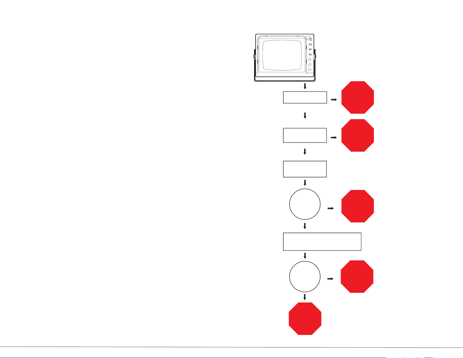
Flowchart B: When monitor screen is black
Monitor screen
is black.
Is monitor power switch
and ignition turned on?
YES
Is green LED on
monitor illuminated?
NO
NO
Turn on
power switch
and/or ignition.
Check power
and ground
connections.
If monitor screen is black:
Make sure power is on and •
ignition is on
Con rm that green LED on •
monitor is illuminated
Check contrast and •
brightness knobs for proper
adjustment
Check power and ground •
connections
Check in-line fuse in •
monitor’s power harness
*These are typical ranges, camera will operate outside these parameters.
YES
Check contrast and
brightness knobs for
proper adjustment.
Adjusted
properly?
YES
Check in-line 3-AMP fuse in monitor
power harness (inside overhead shelf) and
30-AMP ignition mini-fuse at fuse block.
Are both fuses in
good condition?
YES
Replace
monitor.
NO
NO
Make proper
adjustments.
Replace
fuse.
4 9
Page 4
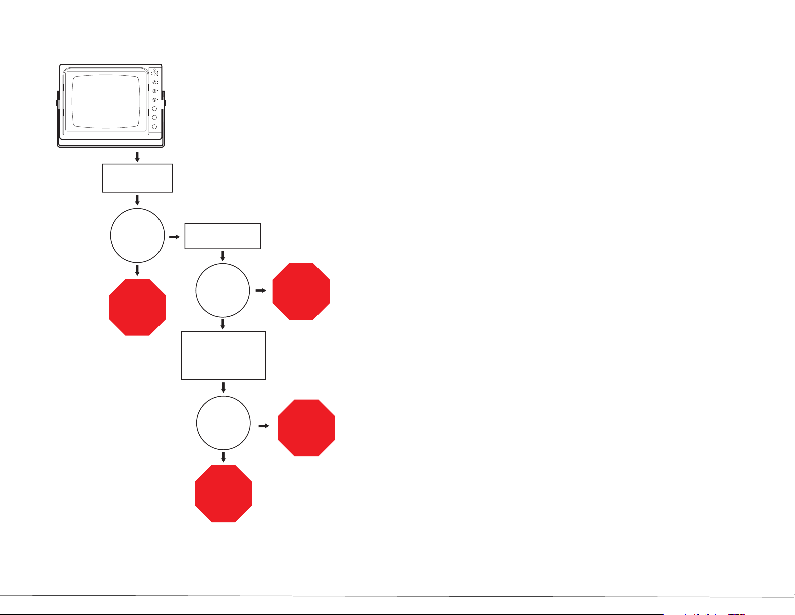
Flowchart C: When monitor screen is white
Contents
SV- 511 System Features ........................................................................................................ 4
Monitor screen
is white
Check contrast and
brightness knobs for
proper adjustment.
properly?
Make proper
adjustments.
Are they
adjusted
NO
YES
Check for obvious
cable damage.
Any obvious
damage?
A continuity check may be
done on the cable at
terminals 2 and 4.
NO
YES
Monitor Controls ...................................................................................................................... 5
Tools Required for Troubleshooting .................................................................................. 7
Operating and Troubleshooting Instructions ................................................................ 7
Troubleshooting Flowcharts ................................................................................................ 8
FCC Compliance Statement ............................................................................................... 11
Replace
the cable.
If monitor screen is white:
Check contrast and brightness •
knobs for proper adjustment
Check for obvious cable damage•
A continuity check should be •
done on the cable at terminals 2
and 4
If the continuity cannot be con-•
rmed on circuits 2 and/or 4, then
replace the cable
Continuity?
NO
Replace
the cable.
YES
Replace
the camera.
10 3
Page 5
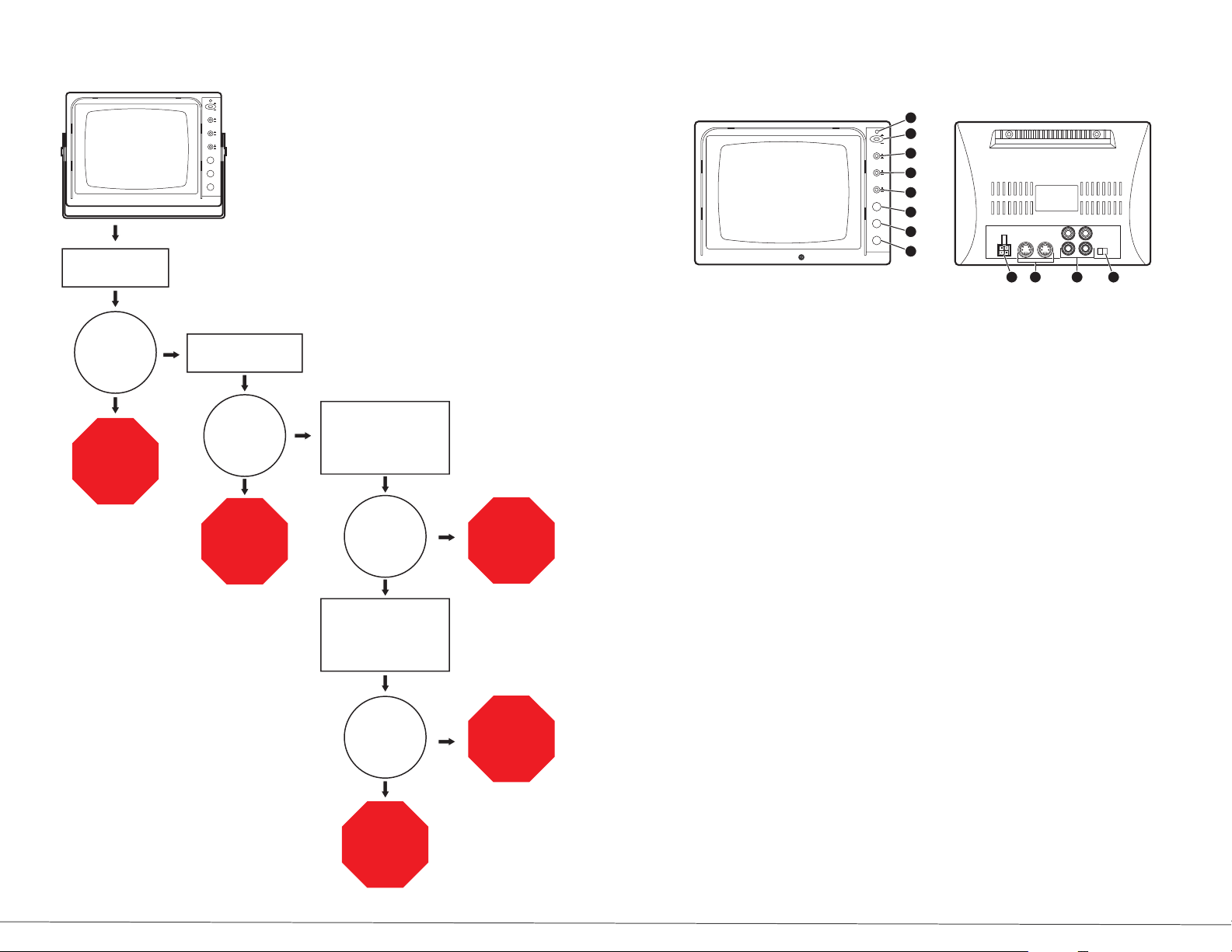
Flowchart A: When monitor has power but no picture
Monitor has power
but no picture
Check DIN connector
on back of monitor.
Monitor Controls
SAFETY VISION
1
S/BY
2
ON
POWER
CA
3
AV
CAMERA
CAM1
CAM2
4
DAY
NIG
5
CONTRAST
6
BRIGHT
7
VOLUME
MIN MAX
®
8
9 10 11 12
Is connector
plugged in
properly?
YES
Check cable connection
at camera.
NO
Is camera
plugged in
Plug connector
properly?
into monitor.
NO
Plug camera
into cable
properly.
Monitor has power but no picture
Check DIN connector on back of monitor
Is connector plugged in properly?•
If so, check cable connection at the •
camera
If camera is connected properly and •
still no picture, unplug the camera
from the cable and check the voltage
at terminal 1 on the cable
If correct voltage is not present at •
terminal 1 on the cable, unplug DIN
connector at the monitor and check
for correct voltage at terminal 1 on the
monitor
If correct voltage is presnt at terminal 1 •
on the monitor, then replace cable
If correct voltage is not present at •
terminal 1 on the monitor, then replace
the monitor
Unplug the camera from
YES
cable and check
the voltage of terminal 1
on the cable.
Is correct
voltage present
at terminal 1
monitor?
Unplug DIN connector
at the monitor and check
for correct voltage at
terminal 1 on the monitor.
Is correct
voltage present
at terminal 1 on
the monitor?
Replace
the monitor.
on the
NO
NO
YES
YES
Replace
the camera.
Replace
the cable.
1) POWER LED
2) POWER SWITCH
Press the power switch (ON) to turn the monitor on. (The Green LED indicator will
illuminate). Press the power switch again to turn the monitor o (Stand By). The
Green LED indicator will not extinguish. The monitor is in the Stand By mode.
3) CAMERA AUDIO/VIDEO SELECTOR
Depress the selector (Ca) to select the camera (Ca1, Ca2). Press the selector (AV)
to select the AV input signal.
4) CAMERA SELECTOR
Depress the camera selector (Ca1) to select the camera connected to “camera 1”.
Press the cameraselector (Ca2) to select the camera connected to “camera 2”.
Two camera ports are standard on rear of monitor.
5) DAY/NIGHT SWITCH
This switch should normally be in the out position (DAY). When you view the
picture at night or in a tunnel, etc, depress the switch to reduce the picture
brightness (NIGHT).
6) CONTRAST CONTROL
Adjust the contrast control for the desired overall best picture. Turn clockwise
to increase picture contrast and counter clockwise to decrease.
7) BRIGHTNESS CONTROL
Adjust the brightness control for the best overall picture or display brightness.
Turn clockwise to increase picture brightness and counter clockwise to decrease
picture brightness.
8 5
Page 6
8) VOLUME CONTROL
Adjust the volume control for the desired sound level. Turn clockwise to
increase and counter clockwise to decrease.
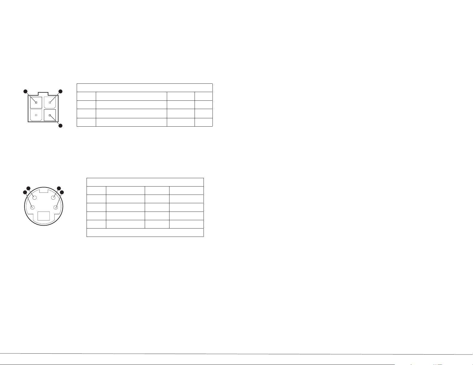
9) MONITOR POWER CONNECTOR
Insert the supplied power cable connector rmly until it is locked. To remove
the power connector, press in the clip and pull out the connector, while
holding the clip down.
1
2
3
Monitor’s Power connector pin description
Pin No. Description Value Tool
3 Red: positive power 10 - 26 VDC DVOM
2 Green: R (reverse) gear power (optional) 10 - 26 VDC CVOM
1 Black: ground
10) CAMERA INPUT CONNECTOR
There are two mini DIN type connectors for the video camera inputs. Connect
the black and white video cameras to the monitor with the supplied cable.
The monitor supplies power to the camera.
1
32
4
Camera input connector pin description
Pin No. Description Value Tool
1 Power Supply 12 VDC DVOM
2 Audio Input 35 decibel Tone generator
3 Image Reverse
4 Video Input 1.0V p-p Oscilloscope
Outer shield of connector housing is ground
Tools Required for Troubleshooting
DVOM (Digital Voltmeter)•
Phillips screw driver #1 and #2•
3/32” allen wrench•
Oscilloscope•
Tone generator•
Terminal tool kit • (such as Snap-On Tt600 if swapping Clarion
components for Safety Vision)
Operating and Troubleshooting Instructions
When you turn the ignition key to the accessory or on position, power is supplied
to the monitor. The system will turn on automatically when the vehicle is
shifted into reverse. Pushing the Power Button, will also manually activate the
system, which allows the operator to use the system while driving. The green
LED on the monitor will illuminate at that time.
Note the power of the monitor:
When you push the power switch to the S/B position, the monitor is placed
in a S/B mode. The monitor is not turned o until the ignition key is in the o
position.
See the following three pages for these conditions:
Monitor has power but no picture • (see Flowchart A)
Monitor screen is black • (see Flowchart B)
Monitor screen is white• (see Flowchart C)
11) VCR JACKS
12) NORMAL/MIRROR OPTION
When the switch is in MIRROR position, the picture will be reversed. When the
switch is in NORMAL position, the picture will be normally displayed. Camera 1
and Camera 2 are operated individually.
76
 Loading...