

Page 1

VISION PRO DIGITAL VIDEO RECORDERS
VISION PRO DIGITAL VIDEO RECORDERS
SITE SOFTWARE USERS MANUAL--
--SITE SOFTWARE USERS MANUAL
1
Page 2

Index
Page 3 MANUAL NOTES
Page 4 CONTENTS
Page 5 REAR PANEL CONNECTIONS
Page 6 8 SENSOR INPUTS & 8 CONTROL OUTPUTS
Page 7 16 SENSOR INPUTS & 16 CONTROL OUTPUTS
Page 8 SETUP
Page 9 HARDWARE SETUP
Page 11 MOTION SETUP
Page 13 SCHEDULE SETUP
Page 14 SCREEN DIVISION
Page 15 MODEM SETUP
Page 16 SITE INFORMATION
Page 17 PASSWORD SETUP
Page 18 AUDIO SETUP
Page 21 SYSTEM SETUP
Page 23 ADD BACKUP SCHEDULE
Page 24 STORAGE SETUP
Page 25 E-MAP
Page 26 DVR OPERATION
Page 28 PAN TILT CONTROL
Page 29 SEARCH MODE
Page 31 SEARCH BUTTONS & FEATURES
Page 33 INDEX SEARCH
Page 34 DATA BACKUP
Page 35 BACKUP TO FLOPPY
Page 36 WATERMARK VERIFICATION OF IMAGE ON DISK
Page 38 DATA BACKUP TO HARD DRIVE, ETC
Page 39 BACKUP TO AVI FILE
Page 40 DATA BACKUP TO CD-RW USING ADAPTEC DIRECT CD
Page 43 AUDIO PLAYBACK
Page 44 PRINTING IMAGES
Page 46 BOOKMARKING IMAGES
Page 47 APPENDIX A CONFIGURING THE DVR FOR CONNECTION OVER PSTN/SDN IP
Page 57 APPENDIX B CONFIGURING THE DVR FOR CONNECTION OVER LAN/WAN IP
Page 58 APPENDIX C PTZ CONNECTION PROTOCOLS
2
Page 3

MANUAL NOTES
MANUAL NOTES
THIS MANUAL COVERS THE FOLLOWING DIGITAL VIDEO RECORDER MODELS
• 430 – 4 CHANNEL 25 FPS MAX MINI DESKTOP UNIT
• 830 – 8 CHANNEL 25 FPS MAX MID TOWER UNIT
• 1630 – 16 CHANNEL 25 FPS MAX RACK MOUNTABLE UNIT
• 4120 – 4 CHANNEL 120 FPS MAX MINI DESKTOP UNIT
• 8120 – 8 CHANNEL 120 FPS MAX MID TOWER UNIT
• 16120 – 16 CHANNEL 100 FPS MAX RACK MOUNTABLE UNIT
• 8240 – 8 CHANNEL 240 FPS MAX RACK MOUNTABLE UNIT
• 16240 – 16 CHANNEL 200 FPS MAX RACK MOUNTABLE UNIT
• 16480 – 16 CHANNEL 480 FPS MAX RACK MOUNTABLE UNIT
THIS MANUAL DEPICTS A 16120 RACK MOUNTABLE UNIT TO DESCRIBE FEATURES.
YOUR UNIT MAY NOT HAVE ALL OF THE FEATURES DESCRIBED.
IF YOU HAVE ANY QUESTIONS ABOUT FEATURES OR OPTIONS PLEASE CONTACT YOUR
DEALER.
INSTALLATION CONSIDERATIONS
z Avoid any place that has high moisture or dust.
z Avoid any place that has direct sun light or heat
z Keep product away from electric shock or any magnetic substance.
z Avoid high or low temperatures.(Recommended temperature is < 72°F)
z Be careful not to drop any conductive material into the fan areas.
z Turn off the system before installation.
z Ensure enough space for the cables at the rear of the system.
z TV or Radio devices might be harmful to the system, or affect performance.
z Don’t disassemble the system without contacting your dealer, doing so will void
the warranty.
z Install UPS or Surge Protector
3
Page 4

CONTENTS
CONTENTS
The packages should contain the following items:
•Digital Video Recorder Unit
•Keyboard
•Mouse
•Software (Windows Disk, DVR Software, ect.)
•Power Cable
Optional Items that may be included.
•Communications Cable
•Serial Port Cable
•Remote Control
•Keys
4
Page 5
REAR PANEL CONNECTIONS
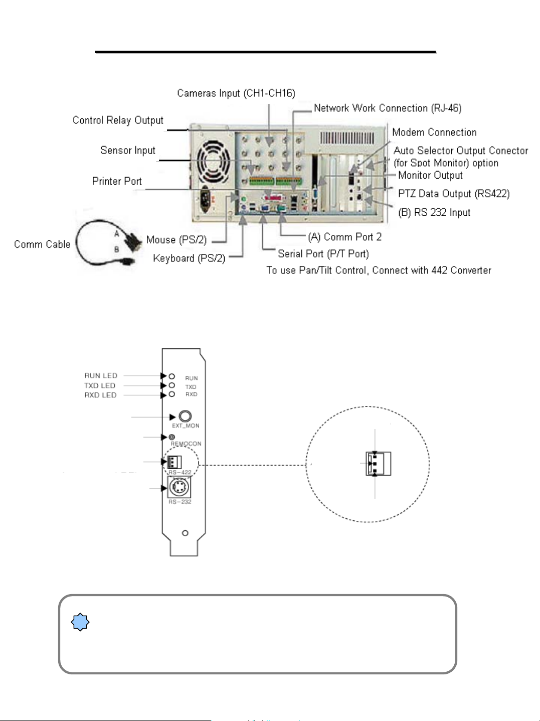
REAR PANEL CONNECTIONS
EXTERNAL MONITOR OUT
REMOTE CONTROL JACK
RS-422 OUTPUT
PLUG FROM COM 1 PORT
CAUTION: Be careful of the polarity of the RS-422 lines
!
Reversing the polarity can damage some equipment. If you have
Questions about what equipment will work with you DVR’s
RS-422 contact your dealer.
SIGNAL +
NOT USED
SIGNAL -
5
Page 6
8 SENSOR INPUTS & 8 CONTROL
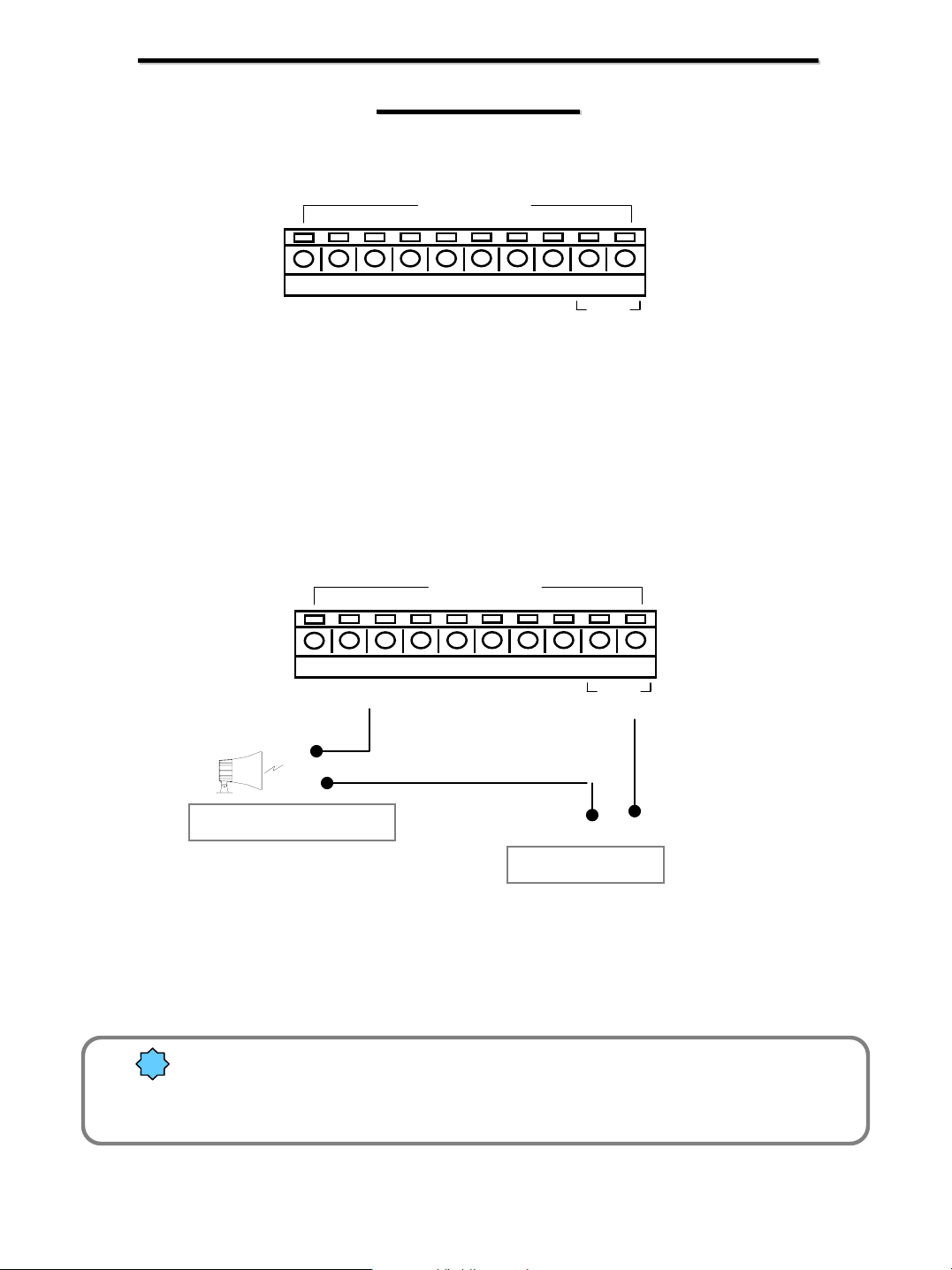
8 SENSOR INPUTS & 8 CONTROL
OUTPUTS
OUTPUTS
SENSOR
2
1
One line of signal line from sensors such as infrared rays, heat perception, magnetic etc,
should be connected to COM connector and the other line is connected to any available
sensor 1-8 connector.
2
1
4
3
4
3
6
5
CONTROL
6
5
8
7
7
8
COM
COM
()()
Alarm, Siren, relay etc.
Power (DC 12V)
¾ The power of the adapter should be no more than 12V and 300mA.
!
¾ An additional external relay should be used to control any higher current
device.
6
Page 7
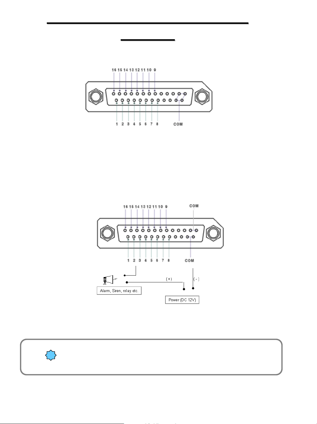
16 Sensor Inputs & 16 Control
16 Sensor Inputs & 16 Control
Outputs
Outputs
One line of signal line from sensors such as infrared rays, heat perception, magnetic etc,
should be connected to COM connector and the other line is connected to any available
sensor 1-16 connector.
()
¾ The power of the adapter should be no more than 12V and 300mA.
!
¾ An additional external relay should be used to control any higher current
device.
7
Page 8
SETUP
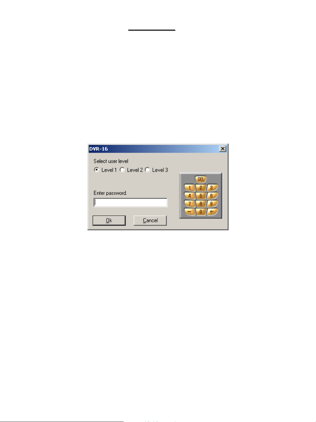
SETUP
Clicking on the Setup button will bring up a password box. The user must select which user level they have
been assigned and then enter their 4 digit password.
The system default level 1 password is blank.
The person who is to be the system administrator will have complete system access and the ability to assign
passwords and setup options for the other users. We recommend that the passwords be written down and
stored in a safe location.
8
Page 9
HARDWARE SETUP
HARDWARE SETUP
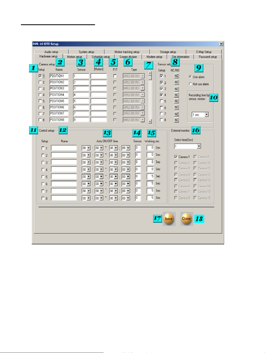
# 1 – Camera Setup – Place a check in the box for each camera that you would like to be turned on. Any
Camera channels that are not being used should be turned off.
# 2 – Camera Name – Each camera can be given a unique name. Up to 14 characters can be entered.
# 3 – Sensor – Enter the sensor numbers that should begin the selected camera recording. If you would like
more than one sensor to activate recording separate the sensor numbers by a comma ex: 1,4.
# 4 – Camera Link – Enter a camera number that needs to begin recording when the sensor is activated that
is tied to the selected camera.
# 5 – Pan Tilt – Place a check in the box if the camera is capable of Pan/Tilt control, and you wish to be able
to have the DVR control its features through the RS-422 output.
9
Page 10

# 6 – If Pan/Tilt is selected choose the type of protocol that your camera uses. If you have any questions
about what Pan/Tilt units will work with your DVR contact your dealer. See Appendix C for connection
diagrams and a list of camera protocols that are available.
# 7 – Sensor Setup – Place a check in the box for each sensor input channel that you would like to be
activated.
# 8 – Type Of Sensor – The system defaults to a NC (Normally Closed Sensor Type) if your sensor is NO
(Normally Open Sensor Type) click on the box to change the type.
# 9 – Use Alarm – Not use Alarm – Select if you would like the system to sound a beep if one of the active
sensors are activated.
#10 – Recording Time by Sensor – Enter the designed recording time upon sensor activation.
# 11 – Control Setup – Place a check mark in the box for each control relay that you wish to activate.
# 12 – Name – You can give each control relay output a unique name. The name can be up to 14
characters long.
# 13 – Auto ON/OFF – You can assign the time that you would like the relay to turn on in the first row, and
the time you would like the relay to turn off in the second row.
# 14 – Sensor – If you would like the control relay to activate with a sensor input, enter the sensor number in
the box.
# 15 – Working Sec – Enter the amount of time in seconds that the control relay will remain active. The
maximum time is 255 seconds, the default time is 0 seconds.
# 16 – External Monitor – The sections lets you select the cameras that you would like to be included in the
switched external NTSC monitor output. You will also have to select the amount of delay that you would like
to have the system wait before switching to the next selected camera.
#17 – Save – After making any changes you must remember to click on the save button. If save is not
pressed before closing, any changes you made will be lost.
# 18 – Close – Exits setup
10
Page 11

MOTION SETUP
MOTION SETUP
# 1 – Recording Frame Rate Per Camera – You can adjust the frame rate for the cameras that are active on
the system. Clicking on “Default” will allocate the system resources automatically between the active
cameras. (This feature is not available on the 18XX Series DVR’s.)
# 2 – Camera – Select the camera that you would like to modify settings for.
# 3 – Sensitivity – The motion detection sensitivity can be adjusted individually for each camera by moving the
adjuster as needed.
# 4 – Alarm & Secure Channel – Place a check in the Alarm box, if you would like the system to provide an
audible alarm when motion is detected. You can also modify the time when the alarm tone will be active.
Place a check in Secure Channel to hide channel from being viewed remotely.
11
Page 12

# 5 – Motion Detection Grid – You can draw up to 5 grids over areas that you would like to have motion
detection active in. To draw a grid click the mouse and drag the area you would like to be active. You
can also move detection areas by clicking and holding the mouse button and moving the area where you
would like it. To delete an area, click and hold the mouse button and move the area off the screen and
then release the mouse button.
# 6 – Area Clear / Area Draw – Clicking on Area Clear will delete the motion detection grids from the
current camera. Clicking on the Area Draw button will put a motion grid over the entire viewing area of
the camera.
# 7 – Brightness, Hue, Contrast – These settings allow you to modify the characteristics of the image.
These changes will be shown on the displayed image as well as the recorded images.
# 8 – Color – This button should be pressed if the selected camera channel has a monochrome camera
connected to it. The button will then display Monochrome. If you have monochrome cameras connected
to some channels and color cameras on other channels, failure to change this setting can result in
improper coloring of some of the images.
# 9 – Default – Clicking here will result in resetting of the individual camera adjustment to factory default.
# 10 – Area Clear – Clicking here will clear the motion detection grids from all system cameras.
# 11 – Area Draw – Clicking here will place a full screen motion detection area on all system cameras.
# 12 – Resolution / Quality – The DVR can support recorded resolutions of 160x120, 320x240, and
640x480. In addition to the resolution setting you can select from 5 quality settings. These settings are
system wide selections. It is important to rememeber that resolution quality settings have a direct impact
on the recording time of the system.
# 13 – Color Of Motion Area – When motion is detected the screen will have a colored box on the outside
edge of a detected zone. You can have either a green or red box.
# 14 – Full Screen When Motion – You can select the cameras that you would like to display full screen
when motion is detected by that camera. The delay should be set to greater than 1 second, to allow
enough time for the operator to see the change. Clicking on the No Full Screen button will clear the
above choices. ( You must separate the above camera’s by a comma, Example 1,2,3,4,)
# 15 – Set Quad Rotation Time – You can choose between 3,5,10 or 30 second rotation time when you
select the quad rotation option from the main screen.
12
Page 13

SCHEDULE SETUP
SCHEDULE SETUP
# 1 – Mode – Clicking here will allow you to select the mode of the schedule.
Simple Mode will allow you to select the recording mode based on the hour of the day.
Advanced mode will allow you to select the recording mode more precisely. You can
modify the time by clicking on the time box and adjusting the slide bar.
# 2 – Camera – Choose the camera that you would like to modify the schedule of.
# 3 – Schedule Range – Select the ranges that you would like to modify.
# 4 – Record Mode – Select the recording method for the range that you have selected. You
can choose from Continuous; Motion; Motion with Sensor; Motion with Sensor and Pre-Alarm;
Sensor; Sensor and Pre-Alarm; and None.
# 5 – Copy To – You can choose to copy the schedule from the selected camera to other
available cameras and even to all the other cameras.
# 6 – Set Holiday – Clicking on this button will allow you to enter Holidays for the system. On
the Holidays you assign the system will use the Sunday/Holiday recording method list.
13
Page 14
SCREEN DIVISION
SCREEN DIVISION
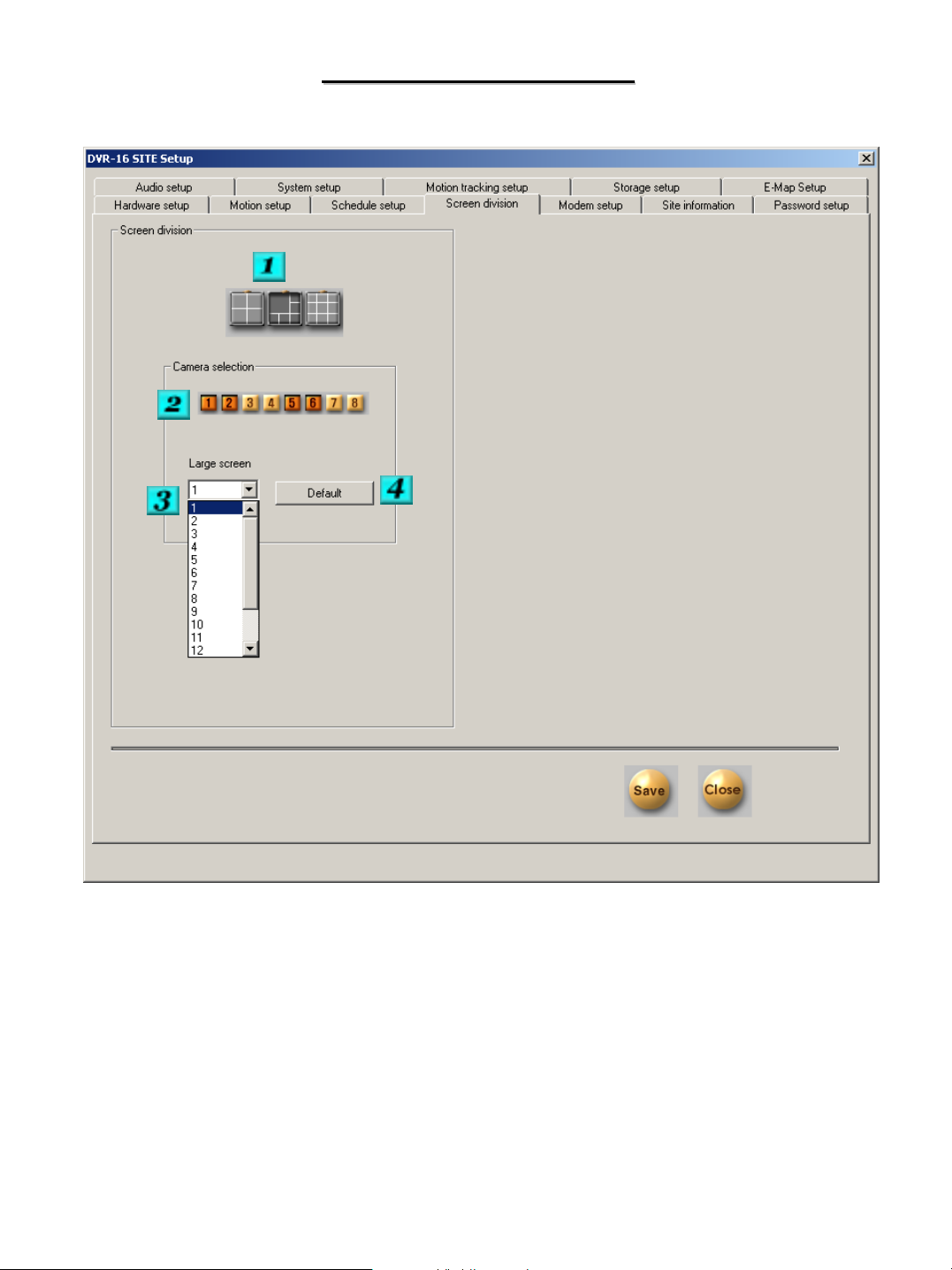
# 1 – Division Selection – Click on the division that you would like to modify.
# 2 –Camera Selection – Select the cameras that you would like to be displayed in the selected division.
# 3 – Large Screen – If the division you are modifying has larger screen sections, you can enter the camera
numbers that you would like in the large screen boxes.
# 4 – Default – Restores the factory defaults for this section.
14
Page 15
MODEM SETUP
MODEM SETUP
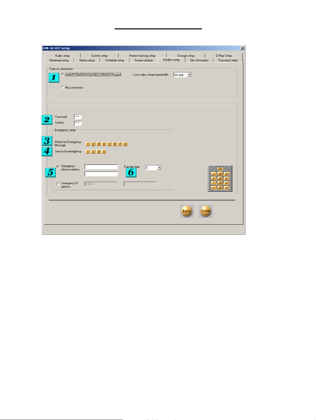
# 1 – Type Of Connection – Choose if you will be allowing remote connections to the DVR to occur.
Selectable network bandwidth. If you would like to use a modem to communicate with center locations, it
may be necessary to run the PPP setup utility. Please see Appendix A for more information.
# 2 – Password – You can enter a 4 digit password to be used when a remote computer attempts to
make a connection. The default password is 1234.
# 3 – Motion For Emergency Messages – Select the cameras that will cause a connection to occur to the
emergency monitoring software. The connection will occur to the Emergency site below.
# 4 - Sensors For Emergency - Select the sensors that you want to cause a connection to the
emergency site listed when the sensor is activated.
# 5 – Emergency Phone Numbers / Emergency IP Address – Select how you would like the DVR to
make an emergency connection, and then enter either the phone numbers or the IP address of the
remote center software.
# 6 – Transfer Time – Select the length of time that the emergency connection should be
maintained. If the situation that caused the connection to occur happens again during the transfer time,
the time will be started again.
15
Page 16
SITE INFORMATION
SITE INFORMATION
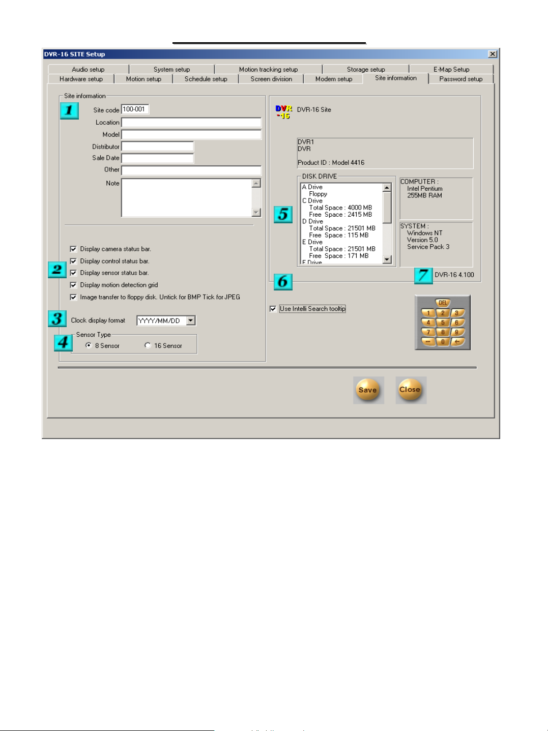
# 1 – Site Information – This section contains information regarding your system. The site number
needs to be unique to your facility, as it is used for remote connections to your DVR. The site code must
be a six digit number in this format 100-001.
# 2 – Choices – You can choose options here such as displaying of various bars and motion grids. You
can also choose if the backup images you would save to a floppy disk will be in .jpg or .bmp format.
# 3 – Clock Display Format – You can choose how you would like your clock to be displayed.
# 4 – Sensor Type – Select whether your system is equipped with either 8 or 16 sensor inputs.
# 5 – System Info – Displays Information about you system, including disk information, memory, etc.
# 6 – Use Intelli Search Tooltip – Place a check in this box to turn on the button tip feature. When you
move over a button in search mode the button name or feature will be displayed.
# 7 – Software Version – Displays your current software version.
16
Page 17
PASSWORD SETUP
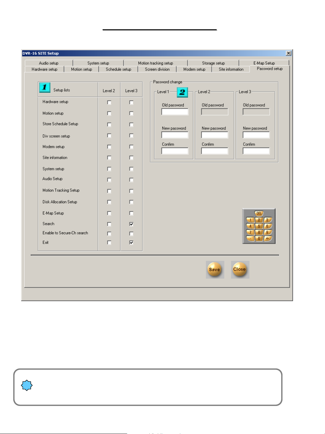
PASSWORD SETUP
# 1 – Setup Lists – Select which items you would like each level to be able to modify or access.
# 2 – Password Change – This section allows you to change the passwords for the 3 levels. The passwords
should be kept in a safe location. We recommend that only one person be allowed to modify passwords.
All Passwords must be 4 digit numbers. Loss of level 1 password can be
!
irreversible.
Please store the password in a safe location.
17
Page 18
AUDIO SETUP
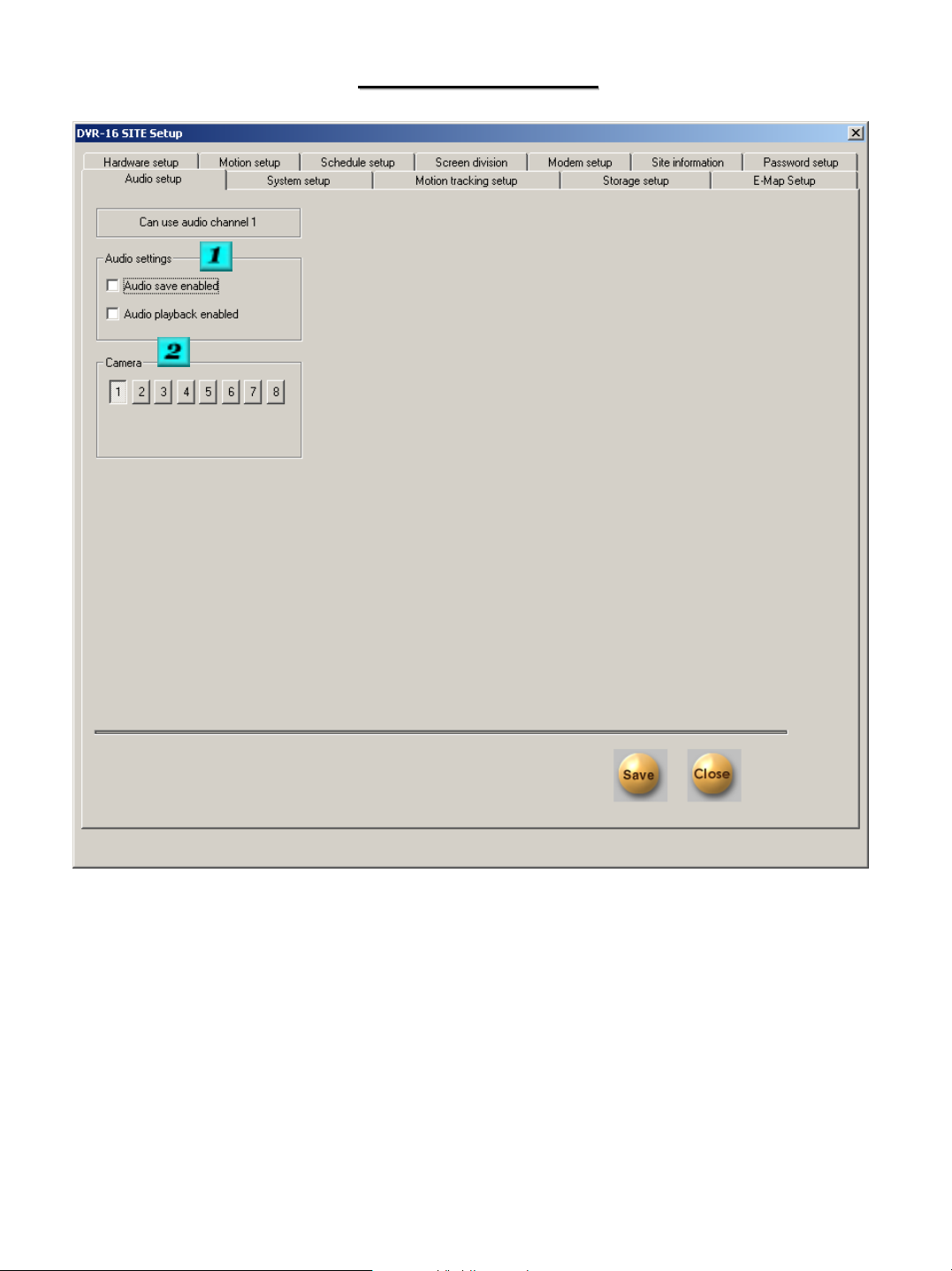
AUDIO SETUP
# 1 – Audio Settings – Place a check in the boxes to activate the features.
# 2 – Camera – Select the camera that the audio will be saved with.
NOTE - Voice recording function will discontinue while connecting 2 Way Audio.
18
Page 19
System setup for Audio function
System setup for Audio function
1
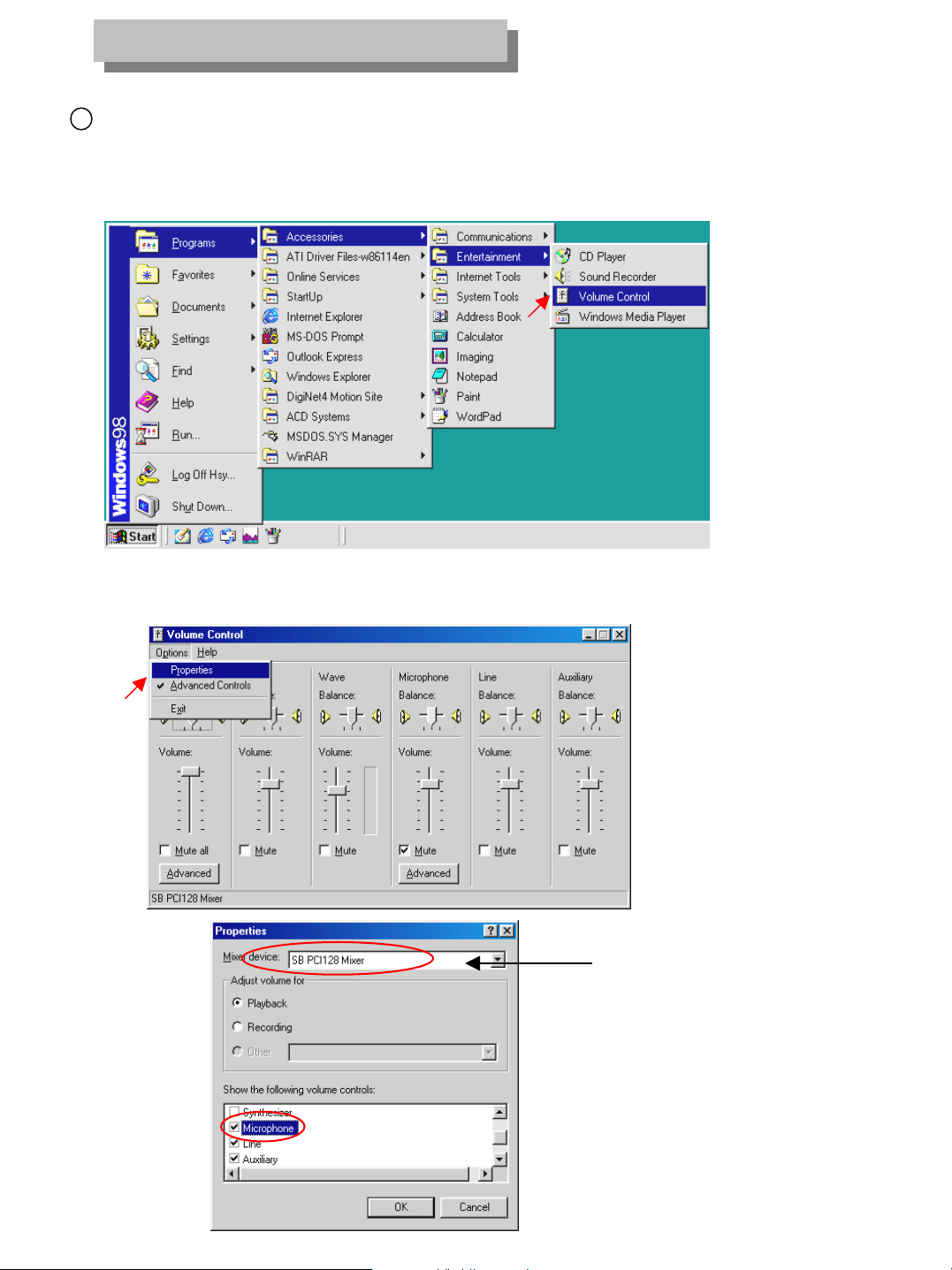
[Audio volume setup for voice recording]
• Prior to recording voice, you need to first control audio volume for microphone.
• Go to ‘Start Æ Program Æ Application Æ Entertainment Æ Volume Control’
• Go to ‘Options Æ Properties’ then, below window will appear.
• In order to use voice recording function
“Microphone” should be set from “Properties” tap.
19
Page 20
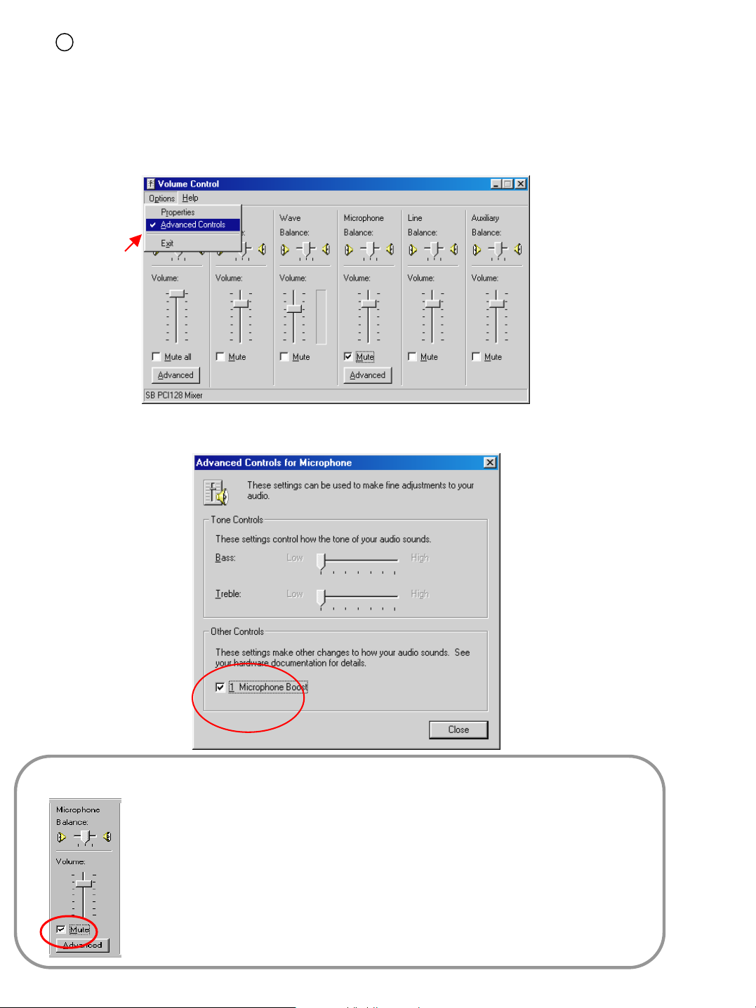
[PC setup for use of Microphone from advanced mode]
2
• When the audio input through microphone is weak even when the volume is maximized you can amplify
the audio input by adjusting as follows.
• ‘Advanced’ button will appear under applicable columns when you select ‘Option -> Advanced Controls
• You can go to ‘Advanced Controls for Microphone’ by clicking ‘Advanced’ on ‘Mic’ taps in ‘Volume Controls’.
• Adjust the options to make your system sound correctly.
[Tips]
• Click on ‘Mute’ which is circled on the left picture, if you do not want the
microphone input to be output through the speakers. This will prevent current audio
and recorded audio from being played together.
• If the system doesn’t support ‘Microphone Boost’ function, ‘Advanced’ button may
not appear. In that case you may need to use a more sensitive amplified
microphone.
20
Page 21

SYSTEM SETUP
SYSTEM SETUP
# 1 – System Off Time – If you would like the system to turn itself off and not reboot automatically, select the
days of the week and the time of the day that you would like to have the system turn off. Use this feature with
caution as the system will turn itself off at this time. The system will have to be powered up again after being
turned off by this section.
# 2 – System Restart Time – The system should be restarted daily to maintain optimal performance. The
default time is 3:00 A.M. if you would like to change the time that this occurs enter the new time in the boxes.
This feature will automatically reboot the system at the specified time. The system will automatically return
itself to the operational state it was in prior to be restarted.
# 3 – Watermark – This feature will provide additional security for the saved images. Place a check mark in the
box if you want to use the watermark feature, and place a check in the box if you want the watermark status to
be displayed when playing saved images.
# 4 – DO NOT MODIFY THESE SETTINGS WITHOUT CONTACTING YOUR DEALER
21
Page 22

# 5 – Easy Update – Clicking here will allow you to update your system to a new software version provided by
your dealer. Your dealer will provide more information if a software version update needs to be performed.
# 6 – Backup Settings – Clicking here will enter the backup section.
#7 – Video Loss Alarm
Backup Settings
# 1 – Schedule - This section shows all of the scheduled backups that have been assigned for the system to
perform.
# 2 – Calendar -The calendar is used to select the dates that you wish to add a backup session for.
# 3 – Add -Click here to add a backup session to the system. You can then select the criteria for the backup.
See the Add Backup Schedule for more information.
# 4 – Delete -Click here to delete a selected backup session.
# 5 – Setup - Click here to accept the changes that you have made .
22
Page 23

ADD BACKUP SCHEDULE
# 1 – Title - Enter the title of the backup session you wish to create.
# 2 – Date/Time - Select the start and end time for when the backup should occur. .
# 3 – Rotate Option - Enter the rotation criteria for the backup you are creating. If the rotation is set to none,
the backup session you are creating will only occur once on the selected time.
# 4 – Backup Start Time Interval After - Select the start time for the backup to begin after the end time that you
have selected is met.
# 5 – Media – This section allows you to select the media that you would like the backup to use. The media list
can contain up to 8 different media locations, any drive that is available to the system can be used for the
backup. Click on Add Media to define were the backup should occur. We do not recommend the use of any of
the systems main drives for the backup. In addition the system can establish a connection to a remote backup
location by IP address. The remote IP system will need to have the Center software installed on this machine
for it to work. The system will make it’s connection to the K-Remote backup Server software that needs to be
running on the remote machine. Refer to the center software manual for more information. You can move a
media type up or down in the list. If the backup process fails on the first media the system will move down the
list and try the next media selection.
# 6 – Overwrite Mode – Check the overwrite box if you would like the newest data to overwrite previous backup
data if there is not enough free space available.
# 7 – Priority – Select the priority that this backup should have in relation to others.
23
# 8 – Add – Click here to add this backup to the list.
Page 24

STORAGE SETUP
STORAGE SETUP
# 1 – Modify Storage Structure – Click on the box to make changes to the storage structure of your DVR.
Once you click close and restart the DVR the storage setup screen will appear.
We recommend that your dealer be contacted for assistance in modifying storage structure.
Changing allocation of drives will result in the drives being formatted and the loss of all stored video
on those drives will occur
24
Page 25

MAP
EE--MAP
E-MAP allows you to display a maps of your facility on the display screen. You can have icons for
the installed cameras, sensors and control relays on the maps to indicate their position in your
facility.
# 1 – Use E-Map – Place a check in the box if you want to use the E-Map feature.
# 2 – Position No. – Select the screen division that you wish to add an E-Map to, then select the
position within that division that you wish to place a map on.
# 3 – User Image Copy - To add your own bitmap click on the “Find>>” button and locate the .bmp
file you wish to use. The bitmap name will be placed in the box. Click on “Go” to copy the image into
that position. The bitmap you wish to use should be in a resolution of 540x360 pixels for best results
# 4 - To add icons to the map select the item number you wish to add and choose a type from the
drop down list. Then click on the location of the item on the map. Click “Save” to accept your
changes.
• The E-Map will be displayed in the selected screen position. You can access each camera by
clicking on it’s icon, the cameras image will be displayed full screen and the pan tilt controls will be
shown if the camera is equipped with these features. The status of any sensors or control relays will
also be indicated on the map.
•Multiple E-Maps can be assigned to each screen division. To add another E-Map to the selected
screen division, repeat the above steps.
25
Page 26

DVR OPERATION
DVR OPERATION
The following sections refer to the below screen shot,
please refer back to this screenshot as necessary.
REC
C1 (POSITION)
Audio
# 1 – Shows the current recording status of the channel.
REC – Continuous M REC –Motion
M:S REC – Motion and Sensor S REC -Sensor
No Mark – Recording is turned off
# 2 – Displays if the available audio recording is being recorded along with the selected
camera.
# 3 – Current date and time display
# 4 – Enters search section for video playback and archiving.
# 5 – Enters the system setup section
26
Page 27

# 6 – Split screen viewing selector (Select the view that you would like the system to display.
Rotating quad view
Full screen view
# 7 – Cameras / Sensor / Control - The buttons indicate which cameras / sensor / control are
active on the system. The buttons will appear depressed when the item is active.
# 8 – Indicates the amount of free hard drive space that is available. When this bar displays 0%
free the system is continuing to record video by deleting the oldest video.
# 9 – Exits the software. You will have to enter a authorized password and the system will then
turn off.
VIEWING CHOICES
VIEWING CHOICES
To view a camera full screen, left click on the camera. To return from full screen mode left click
again. Continuing to right click on the image will cycle through different image sizes.
27
Page 28

PAN TILT CONTROL
PAN TILT CONTROL
If your cameras are equipped with Pan/Tilt control you can enter the control section by
clicking on the image you wish to control. The camera controls will be shown
To return to the display mode click on
the Quit button in the lower right corner.
The controls will vary depending on what
camera you are controlling. The controls
shown are for a GC-755 Zoom Camera. The
complete list of protocols can be seen under
the hardware setup section. If you have
questions about controlling your specific type
of equipment, please refer to Appendix C, or
contact your dealer.
28
Page 29

SEARCH MODE
SEARCH MODE
Upon entering search mode you will be prompted to select your user level and enter
your password. Upon successfully completing the password section the bellow
search screen will appear.
# 1 – Calendar – The calendar will allow the user to see which days have stored video.
Days that are darker have recorded video. The current day is displayed in green. To
begin select the day that you need to review.
# 2 – Graph – Once the date is selected you will see the status of the recorded video
throughout the day. You can either move the slide bar to the period of time you wish to
review or enter the time in the Hour / Minute section. The next page explains what is
displayed by the graph. You must select the cameras that you would like included in the
playback, you can then select the play method from the buttons. The system will
automatically display the correct grid to allow for all the selected cameras to be displayed.
You can also click on the hour bar above the graph to see the time breakdown more
precisely. Continuing to click on the hours will return the graph to normal.
29
Page 30

Intelli-Search Bar
Camera selection bar Recording status graph Search time selection bar
This function shows the recording mode and when there was recording.
The colors on the graph depict the status of the recording.
Purple – Continuous : Blue – Motion : Green – Pre Alarm
If there is not a colored bar present there was no recording during that period.
You can also click on the hour bar above the graph to see the time breakdown more
precisely. Continuing to click on the hours will return the graph to normal.
30
Page 31

SEARCH BUTTONS & FEATURES
SEARCH BUTTONS & FEATURES
Adjusting hour or minute after selecting Day on calendar
Primary source for adjusting hour and date is to click on
slider bar on graph and let loose of mouse button after
positioning.
Panoramic playback allows you to play back the selected
camera in multiple grid modes frame by frame
Zoom resizes the entire image
Digital Zoom
Zoom In Zoom Out Move
Intelli Search Refresh
Brightness Adjust
Noise Reduction Adjust
Smoothness & Sharpness Adjust
Contrast Adjust
Deskew (Rotate the distorted image to adjust)
Gamma Correction (When the color is to strong weak)
Rotation (rotate image 90 °, 180°, 270° and flip)
Source (Returns the image to it’s recorded state)
- Screen Division
->
31
Page 32

Opens the print dialog to allow you to
print the selected image
Opens The Data Backup
Section
Opens The Bookmark Section
Opens The Audio Playback Section
Turns On/Off Recording While In Search
Mode (Searching Performance Is
Improved If Turned Off)
Select all cameras
Index Search
Index Search Panel
•Skip – adjusting this allows the
System to skip frames during playback
•Delay – adjusting this slows down or
Speeds up playback
1 2 3 4 5 6 7
1. Go to beginning of the recording 4. Stop
for the day 5. Play forward
2. Go back 1 frame 6. Go forward 1 frame
3. Play in reverse recording 7. Go to the end of the
for the day
32
Page 33

INDEX SEARCH
#1 - Select expand to select all cameras available
# 2 – Clicking on this button will display the advanced Index search section above.
The index will display the index of recorded images for the time that you have selected. You can select
the recorded time frame from the list and the image will be displayed. You can also choose what criteria is
Included in your displayed selection.
The cameras that have recording for the day will be shown along with the choices for the type of recording that
was done. All, pre alarm, sensor and motion. You can select or deselect the types of recording to isolate the type
of recording you would like to see on the graph. Clicking on (A) in the all row will cause the graph to display all the
recording that has occurred. Clicking on (N) in the all row will clear the graph. Clicking on (A) in all other rows will
add that type of recording to the graph, clicking on the (N) will remove that type of recording from the graph.
#3 - Index Search Panel
33
Page 34

DATA BACKUP
DATA BACKUP
# 1 – Clicking on this button will bring up the Data Backup section below.
You can then select the type of backup that you wish to perform.
34
Page 35

BACKUP TO FLOPPY
BACKUP TO FLOPPY
Before making an image backup to a floppy disk you must have the image displayed by itself on the
screen before entering the backup section. If you don’t do this you will not be able to select the
backup to floppy option.
Once the image that you want to save is displayed you can choose to save a single image to a floppy
disk if you wish.
# 1 – If you select the floppy backup option, and click on save the system will display the
below message if you have chosen to use the Watermark feature, otherwise the
image will be saved without the watermark program.
• If you click “Yes” the watermark utility along with the image will be saved to the floppy .
You can transfer as many single images as you have room for to the floppy disk, however, you only
need to copy the watermark check program once.
!
The image will be copied onto a floppy diskette in BMP or JPG format, depending on your
selection under setup. The image will be copied with the ‘watermark checker program’ which will
allow you to ensure that the image remains unchanged during future review.
35
Page 36

WATERMARK VERIFICATION OF IMAGE ON DISK
WATERMARK VERIFICATION OF IMAGE ON DISK
Run the watermark check program by running the file
‘WMChecker.exe’ on the floppy disk. The following image will appear.
# 1 – File Open – Clicking here will bring up the box below. Select the file that you would like to
verify, and click open.
36
Page 37

Once opened the name of the file will appear in the window. Select Watermark check to verify the image.
Once verification has been completed, windows similar to those below will appear.
Corrupted image Uncorrupted image
37
Page 38

DATA BACKUP TO HARD DRIVE, ETC
DATA BACKUP TO HARD DRIVE, ETC
This is used to backup a large volume of images.
# 1 – Select the start and end time and date for the backup you wish to make.
# 2 – Click on this button to estimate the amount of space that your selected time backup will require.
The box below will appear with the estimated amount of space that is needed.
# 3 – Click on this button to select the media type you would like to use for the backup. You can
select from any available drive such as mapped network drive, zip, hard drive, etc. You can also
select a remote IP address that the system will backup to as shown below.
# 4 – Format CD-R/CD-RW – This button works with Roxio Direct CD to format a blank CD. Direct
CD must be installed on the system in order for this feature to work. (SEE Direct CD Section of the
manual)
# 5 – Placing a check in this box will delete the old backup data when there is not enough free space
to complete the backup.
# 6 – You can choose the priority of the backup here.
The backup icon will be displayed on the top of the screens while any backups are accruing.
38
See the Center Software Manual for information on replaying Backup Data!
Page 39

BACKUP TO AVI FILE
#1 - This feature functions like the time backup, except the backup that is created will be in AVI
format. This allows the video segment to be played on many standard media players. The
maximum time for each AVI backup is 5 minutes.
#2 - You will need to select the times for the backup and the cameras that you would like to be
included in the AVI file. The backup icon will be displayed at the top of the search screen while
the process completes.
* AVI backups can take an extended period of time depending on the size of the backup. *
39
Page 40

DATA BACKUP TO CD--
DATA BACKUP TO CD
ADAPTEC DIRECT CD
ADAPTEC DIRECT CD
In order to use Adaptec Direct CD to store backup DATA, you must first format a blank CD-R or CDRW. After clicking on the format CD/R / CR-RW button from the backup section, the below screen
should appear. If it does not you may have to press ALT and Tab to cycle to the Direct CD Utility.
Once the below screen shot appears insert a blank CD into the drive, you must allow for a few
seconds for the system to recognize the disk. Once the status shows “Blank CD” you can proceed.
RW USING
RW USING
#1 - Click on Format CD
#2 - Enter a name for the CD and click Start Format
40
Page 41

When the CD is being formatted the below section will be displayed.
#1 – Click on OK to complete the format. You then need to exit the Direct CD
program. The CD can now be used as a writeable media from the select media
option. Follow the same procedures for a backup to hard drive, ect. Once your
backup is complete and you need to remove the CD, press the eject button. The
below screen shot will appear.
41
Page 42

Once your backup is complete and you need to remove the CD, press the eject button. The
below screen shot will appear.
Select the “Leave As Is” option if you wish to be able to insert the CD and write more data to the CD. If you
are done and want to finish the CD select the “Close to Read on Any Computer” option. You can also
choose if you would like to protect the CD so it cannot be written to again. Once the CD is completed it can
be played back on a computer with center software installed on it.
42
Page 43

AUDIO PLAYBACK
AUDIO PLAYBACK
# 1 – Audio Play Control – When you click this button the audio
play configuration window will appear. Select the playback
level and then click on enable to allow for audio playback.
Audio can be played back only when one camera is selected.
You must select only the camera that contains the audio.
Audio can be played in normal forward play mode only. You
cannot playback audio while using reverse play, frame play,
skip or delay.
Video loss can occur during the first 1-3 seconds of playback,
this is due to the video and audio becoming synchronized, it is
not a fault of the system
43
Page 44

PRINTING IMAGES
PRINTING IMAGES
# 1 –Printing the selected image.
After adjusting size and brightness you can print the image to any available system printer.
!
When the system is not setup properly for Printing, the below error might appear.
44
Page 45

* If you have trouble printing, please make sure that your printer is
setup properly.
Installing printer
1. In Windows 98/2000 click Start->Setting->Printers.
2. In Printers window, select and click Add Printer.
3. In Add Printer window, click Next.
4. Click the manufacturer and model of your printer.
5. Click available port.
6. If your printer is not listed on screen, consult with your printer dealer.
Printed image size
!
The printed image size is related to the size of the image being displayed on the screen
45
Page 46

BOOKMARKING IMAGES
BOOKMARKING IMAGES
# 1 – Bookmarking Image -If you have located an image that you would like
to save an easy reference to, or to retrieve a stored reference, click on the
bookmark icon. The below window will appear.
To save a reference to the image click on the “ADD” button. The date and time of
the file will be placed in the list. Enter a description to allow for easy identification.
To delete a reference, select it from the list and click on the “DELETE” button. To d
elete all the references, click the “DELETE ALL” button.
To retrieve a stored reference click on the reference, and click the “GOTO” button.
The time and date of the search will be returned to the time of the selected reference.
46
Page 47

Appendix A
Configuring the DVR for Connection over PSTN/SDN
1. Ensure that your modem or ISDN Terminal Adapter are correctly Installed.
2. Guest user setup and password setup
- Double click on “Users and Passwords” in Control Panel.
- Select “Advanced” in tab menu in “Users and Passwords” and select “Advanced” button in
“Advanced User Management”.
47
Page 48

- Select “Guest” in “User” menu and select Guest “Properties” by right clicking on “Guest”.
- Uncheck on “Account is disabled” in “General” tab menu.
48
Page 49

- Select “Guest” in “User” menu and select “Set Password” by right clicking on “Guest”
- Type New password and Confirm password as “1234” and click [OK]. (Password must be “1234”.)
- Password confirmation. Press [OK].
49
Page 50

3. KPPPSETUP.EXE Program
- You must run KPPPSETUP.EXE to allow for a remote connection using a modem in Windows 2000.
Explore the C: Drive and locate the “DVR-16 Center” folder. Locate the KPPPS Setup exe. File and
execute it. The process will complete automatically.
50
Page 51

4. Network and Dial-Up Connections Setup
- Double click on “Network and Dial-Up Connections” in Control panel.
- Right click on “K Network” and Click on “Properties”.
51
Page 52

- Select “Security” on tab menu. Select “Advanced (custom settings) and Click on [Settings].
- Set the below options and click [OK].
Data Encryption: Optional encryption (connect even if no encryption)
Logon Security: Select “Allow these protocols”
√ Microsoft CHAP (MS-CHAP)
√ Allow older CHAP version for Windows 95 servers
√ Microsoft CHAP version 2 (MS-CHAP v2)
52
Page 53

- In “Network” on tab menu, select “PPP: Windows 95/98/NT4/2000, Internet”. Then click on ok.
53
Page 54

5. Incoming Connection Setting
- In “Network and Dial-Up Connections”, right-click on “Incoming Connections” and select
“Properties”.
- Check the modem that is being to be used in “General” tab menu.
54
Page 55

- In “User” on tab menu, select “Guest” in “Users allowed to connect”.
- In “Networking” on tab menu, select “Internet Protocol (TCP/IP)” and click on [Properties].
55
Page 56

- Change settings as below and click [OK],
Network Access: “Allow callers access my local area network”
TCP/IP address assignment:
From: 192.168.55.1
255.255.255.0
To:
“Specify TCP/IP addresses”
Click on “OK” to complete the setup process. Your DVR should now allow both
incoming and outgoing connections to be made over your modem or ISDN adapter.
Refer to the Center Software Manual for information on making a connection to or from a
remote site.
56
Page 57

Appendix B
Configuring the DVR for connection over LAN/WAN IP
Address
The DVR must be assigned a static IP address to allow it to connect over a LAN/WAN environment.
As multiple networking environments are present in today’s systems assistance should be gathered
from your networking technician.
To Assign a static IP address:
Right click on “My Network Places” on the desktop and select properties. Locate the “Local Area
Move down Connection” Icon and right click on it to select “properties”. Select “Internet Protocol
TCP/IP” and select properties. Select “Use the following IP address” and enter the information
provided by your network technician.
The DVR will communicate over the assigned IP address using port 8080. The network
configuration must allow the connection on pont 8080 for the connection to function correctly.
57
Page 58

Appendix C
PTZ Connection Protocols
The Digital Video Recorder currently supports Pan tilt PTZ. See the diagrams on the
following pages for PTZ equipped camera’s. If you have any further questions please
contact your dealer.
Compatible PTZ Equipment List
HONEYWELL GC-455N-K RX
KALATEL KALATEL
PELCO KRX-3200 RX
NIKO NK-97 SD
DYNACOLOR D7720 SD
VICON V1311RB-3W (RX) / V1311R-VPS-1
VICON VICON SD
SAMSUNG SPD_1600 SD
INTERM VRX-2101 RX
LILING LILIN SD
PANASONIC WV-CS854 SD
ORIENTAL ORIENTAL RX (ORX-1000)
COMEX COMEX RX (CCS-256R)
DONGYANG DRX-501A RX
KODICOM KRE-301 RX
SENSORMATIC RAS716-LS SD
SAMSUNG SRX-1000
HONEYWELL GC-755
LONG HUNDA RM110
PHILLIPS LTC
PELCO C1489M-D
DONGYANG DY-255RXB #1.4
DENARD TYPE 2050
ERNA ERNA
LG GAC-PT1
RG PT-101
VIDEOTEC DTRX (PROFLY 320)
PROFLY SD DYANCOLOR SD
SOTEK SD LILIN SD
SAMSUNG SCC-641 SD
CELOTEX TOYANI SD
SUNGJIN SUNGJIN RX
PELCO PELCO-D SD
CANON CANON VC-C4
DIGITEL MH-209 RX
UNIMO KRX-2101 RX
DAIWA DMP-22 SD
58
Page 59

NK-97(CHE)
NIKO
RS-422(+)
RS-422(-)
KIO-1616
POWER
2
POWER
3
RXD-
4
RXD+
51
TXD-
7
TXD+6FGND
59
Page 60

RAS715(6)-LS
Sensormatic
RS-422(+)
RS-422(-)
KIO-1616
2
-
NOT
USE
NOT
USE
3
BLACK
4
RED
51
WHITE-
24V ACGND24V AC
6
ORANGE
7
GREEN
RXD-RXD+
8
YELLOW
TXD+
9
BROWN
TXD-
60
Page 61

PIH-717X
LILIN
RS-422(+)
RS-422(-)
KIO-1616
12
TXD-
13…
TXD+
14…
RXD-
15
RXD+
61
Page 62

Dynacolor
RS-422(+)
RS-422(-)
KIO-1616
-
2
POWER
3
GND
4
DA+
51
DB-
6
-
62
Page 63

WV-CS854
Panasonic
RS-422(+)
RS-422(-)
KIO-1616
-
GREEN
RXD+
YELLOW
RXD-
ORANGE
TXD+
RED
TXD-
BROWN
GND
63
Page 64

TOA
CBC
RS-422(+)
RS-422(-)
KIO-1616
2
B-
3
A+
4
B-
51
GNDA+
64
Page 65

KTD-313-1
KALATEL
RS-422(+)
RS-422(-)
KIO-1616
POWER
2
POWER
Connect to Digiplex
3
A+
4
B-
51
A+
6
B-
65
Page 66

SPD-1600
SAMSUNG
RS-422(+)
RS-422(-)
KIO-1616
VIDEO(+)
2
VIDEO(-)
3
POWER
12V
4
POWER
GND
5
POWER
12V
6
LINE
LOCK
SYNC
7
DATA
+
81
DATA
-
9
GND
66
Page 67

SCC641
SAMSUNG
RS-422(+)
RS-422(-)
KIO-1616
10
TX+
11
TX-
67
Page 68

V1311R-VPS
VICON
RS-422(+)
RS-422(-)
KIO-1616
9
GND
10
+
11
-
68
Page 69

C1487M-E
PELCO
RS-422(+)
RS-422(-)
KIO-1616
RX- TX+RX+ TX-
69
 Loading...