

Page 1
Vision™ OPLC™
This guide provides basic information for Unitronics’ LCD color touchscreen models
V290-19-C30B and V290-19-T40B.
Installation Guide
V290 (Color)
General Description
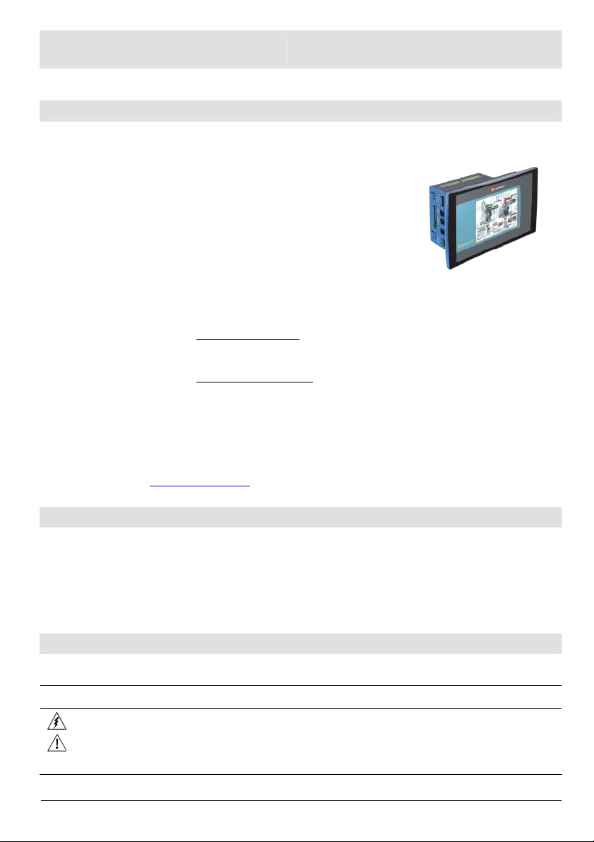
Vision OPLCs are programmable logic controllers that comprise an integral operating panel.
Operating panel features differ according to model.
The V290-19-C30B and V290-19-T40B offer a color touchscreen,
which displays a virtual keyboard when the application requires the
operator to enter data.
Communications
I/O Options
Programming
2 isolated RS232/RS485 ports
and a CANbus port.
The user can order and install an
additional port. Available port
types are: RS232/RS485, and
Ethernet.
Vision supports up to 171 digital, high-speed, and analog I/Os via modules.
Number of I/Os and types vary according to module.
Snap-in I/O Modules
Plug into the back of the controller to provide an on-board I/O
configuration.
I/O Expansion Modules
Via adapter, use up to 8 I/O Expansion Modules comprising up to
128 additional I/Os.
Write both the HMI and Ladder control application using VisiLogic freeware.
V290 (Color Screens)
Touchscreen only
The Vision User Guide and the product’s technical specification sheet contain additional information.
These documents are located on the Unitronics’ Setup CD. They may also be downloaded from the
Technical Library at www.unitronics.com.
Standard Kit Contents
Vision controller Programming cable + RS232 adapter
Mounting brackets (x4) Grounding hardware
3 pin power supply connector Rubber seal
5-pin CANbus connector Unitronics’ Setup CD
CANbus network termination resistor
Danger Symbols
When any of the following symbols appear, read the associated information carefully.
Symbol Meaning Description
Danger The identified danger causes physical and property damage.
Warning The identified danger could cause physical and property damage.
Caution Caution Use caution.
Unitronics 1
Page 2

Vision™ OPLC™ V 290-19-C30B, V290-19-T40B
Before using this product, the user must read and understand this document.
All examples and diagrams are intended to aid understanding, and do not guarantee operation.
Unitronics accepts no responsibility for actual use of this product based on these examples.
Please dispose of this product according to local and national standards and regulations.
Only qualified service personnel should open this device or carry out repairs.
Failure to comply with appropriate safety guidelines can cause severe injury or property damage.
Do not attempt to use this device with parameters that exceed permissible levels.
To avoid damaging the system, do not connect/disconnect the device when power is on.
Environmental Considerations
Do not install in areas with: excessive or conductive dust, corrosive or flammable gas,
moisture or rain, excessive heat, regular impact shocks or excessive vibration, in
accordance with the standards given in the product’s technical specification sheet.
Ventilation: 10mm space required between controller’s top/bottom edges & enclosure walls.
Do not place in water or let water leak onto the unit.
Do not allow debris to fall inside the unit during installation.
Install at maximum distance from high-voltage cables and power equipment.
Mounting
Dimensions
2 Unitronics
Page 3
Installation Guide
Panel mounting
Before you begin, note that:
The mounting panel cannot be more than 5 mm thick.
To minimize electromagnetic interference, mount the controller on a metal panel and
earth the power supply according to the details in step 2 below.
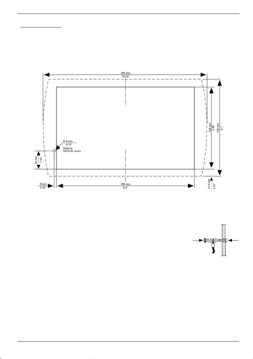
1. Make a panel cut-out according to the dimensions shown below.
Cut-out Dimensions
2. If you mount the controller on a metal panel, earth the power supply:
a. Bore a hole to suit the NC6-32 screw supplied with the kit.
b. Scrape panel paint away from the contact area to ensure a conductive
connection.
c. Drive the screw into the hole.
d. Place the following hardware screw’s shank, in the order shown in the
accompanying figure: washer, ring cable shoe, second washer, spring,
and nut.
Note:
The wire used to earth the power supply must not exceed 10 cm in
length. If your conditions do not permit this, do not earth the
power supply.
Unitronics 3
Page 4

3. Slide the controller into the cut-out, ensuring
that the rubber seal is in place.
4. Push the 4 mounting brackets into their slots
on the sides of the controller as shown in the
figure to the right.
5. Tighten the bracket screws against the
panel. Hold the bracket securely against the
unit while tightening the screw.
6. When properly mounted, the controller is
squarely situated in the panel cut-out as
shown in the figure to the right.
Vision™ OPLC™ V 290-19-C30B, V290-19-T40B
I/O Modules
I/Os are integrated into the system via Snap-in Modules and I/O Expansion Modules. Installation
instructions and other data may be found in the module’s technical specification sheet.
Wiring: General
Do not touch live wires.
Unused pins should not be connected. Ignoring this directive may damage the device.
To avoid damaging the wire, do not exceed a maximum torque of 0.5 N·m
Caution
Use crimp terminals for wiring; use 26-14 AWG wire (0.13 mm 2–2.08 mm2).
1. Strip the wire to a length of 7±0.5mm (0.250–0.300”).
2. Unscrew the terminal to its widest position before inserting a wire.
3. Insert the wire completely into the terminal to ensure a proper connection.
4. Tighten enough to keep the wire from pulling free.
4 Unitronics
(5 kgf·cm).
Do not use tin, solder, or any substance on stripped wire that might cause the wire
strand to break.
Page 5

Installation Guide
isolated external device,
Power Supply
The controller requires an external 24VDC power supply. The permissible input voltage range is
20.4-28.8VDC, with less than 10% ripple.
A non-isolated power supply can be used if a 0V signal is connected to the chassis.
You must use an external circuit protection device.
Install an external circuit breaker. Guard against
short-circuiting in external wiring.
Double-check all wiring before turning on the power
supply.
Do not connect either the ‘Neutral or ‘Line’ signal of
the 110/220VAC to device’s 0V pin.
In the event of voltage fluctuations or non-conformity
to voltage power supply specifications, connect the
device to a regulated power supply.
To avoid electromagnetic interference, earth the
power supply as described on page 3.
Communication Ports
This series comprises 2 RS232/RS485 serial ports and a CANbus port.
Turn off power before making communications connections.
Caution
Serial Communications
The serial ports are type RJ-11 and may be set to either RS232 or RS485 via DIP switches, in
accordance with to the table shown on page 7.
Use RS232 to download programs from a PC, and to communicate with serial devices and
applications, such as SCADA.
Use RS485 to create a multi-drop network containing up to 32 devices.
Caution The serial ports are isolated. If the controller is used with a non-
Pinouts
The pinouts below show the signals between the adapter and port.
RS232 RS485** Controller Port
Pin # Description Pin # Description
1* DTR signal
2 0V reference
3 TXD signal
4 RXD signal
5 0V reference
6* DSR signal
*Standard programming cables do not provide connection points for pins 1 and 6.
**When a port is adapted to RS485, Pin 1 (DTR) is used for signal A,
and Pin 6 (DSR) signal is used for signal B.
Signals are related to the controller’s 0V; the same 0V is used by the power supply.
Always use the appropriate port adapters.
avoid potential voltage that exceeds ± 10V.
1 A signal (+)
2 (RS232 signal)
3 (RS232 signal)
4 (RS232 signal)
5 (RS232 signal)
6 B signal (-)
Pin #1
Unitronics 5
Page 6

Vision™ OPLC™ V 290-19-C30B, V290-19-T40B
RS232 to RS485: Changing DIP Switch Settings
The ports are set to RS232 by factory default.
To access the DIP switches, first remove the Snap-in I/O Module, if one is installed, and then
remove the back of the controller.
Before removing a Snap-in I/O Module or opening the controller, you must turn off the
.
power
Removing a Snap-in I/O Module
1. Locate the four buttons on the sides of the controller, two on either side.
2. Press the buttons and hold them down to open the locking mechanism.
3. Gently rock the module from side to side, easing the module from the controller.
Opening and Closing the Controller
1. Locate the slots on the sides of the
controller.
2. Open the controller by inserting a
flat-bladed screwdriver into the
slots located on the side of the
controller, then carefully prying off
the rear panel.
3. Locate the DIP switches, and then
change the settings as required.
Settings are shown on page 7.
4. Close the controller
by snapping the
plastic cover back in
its place.
6 Unitronics
Page 7

Installation Guide
Re-installing a Snap-in I/O Module
1. Line the circular guidelines on the controller up with the guidelines on the Snap-in I/O Module as
shown below.
2 Apply even pressure on all 4 corners until you hear a distinct ‘click’. The module is now installed.
Check that all sides and corners are correctly aligned.
RS232/RS485: DIP Switch Settings
Switch Settings
1 2 3 4 5 6
RS232* ON ON ON
RS485
RS485 with
OFF OFF OFF
ON ON
OFF
OFF
ON
ON
termination**
*Default factory setting
**Causes the unit to function as an end unit in an RS485 network
ON
OFF
OFF
OFF
ON
ON
Unitronics 7
Page 8

Vision™ OPLC™ V 290-19-C30B, V290-19-T40B
121
terminating
resistor
121
terminating
resistor
+
CANbus
These controllers comprise a CANbus port. Use
this to create a decentralized control network of
up to 63 controllers, using either Unitronics’
proprietary CANbus protocol or CANopen.
The CANbus port is galvanically isolated.
CANbus Wiring
Use twisted-pair cable. DeviceNet® thick
shielded twisted pair cable is recommended.
Network terminators: These are supplied with the
controller. Place terminators at each end of the
CANbus network.
Resistance must be set to 1%, 121Q, 1/4W.
Connect ground signal to the earth at only one
point, near the power supply.
The network power supply need not be at the
end of the network
CANbus Connector
24V Power
Supply
-
Circuit
protection
device
-V
L
PE
H
+V
V
-
L
PE
H
V
+
-V
L
PE
H
+V
The information in this document reflects products at the date of printing. Unitronics reserves the right, subject to all applicable laws, at any time, at its sole
discretion, and without notice, to discontinue or change the features, designs, materials and other specifications of its products, and to either permanently or
temporarily withdraw any of the forgoing from the market.
All information in this document is provided "as is" without warranty of any kind, either expressed or implied, including but not limited to any implied warranties of
merchantability, fitness for a particular purpose, or non-infringement. Unitronics assumes no responsibility for errors or omissions in the information presented in
this document. In no event shall Unitronics be liable for any special, incidental, indirect or consequential damages of any kind, or any damages whatsoever arising
out of or in connection with the use or performance of this information.
The tradenames, trademarks, logos and service marks presented in this document, including their design, are the property of Unitronics (1989) (R"G) Ltd. or other
third parties and you are not permitted to use them without the prior written consent of Unitronics or such third party as may own them.
8 Unitronics
11/06 DIG-V290-CT
 Loading...