

Vishay VS-15ETX06PbF, VS-15ETX06FPPbF Data Sheet
VS-15ETX06PbF, VS-15ETX06FPPbF
TO-220AC TO-220 FULL-PAK
Anode
1
3
Cathode
Base
cathode
2
Anode
1
3
Cathode
VS-15ETX06PbF VS-15ETX06FPPbF
Vishay Semiconductors
Ultrafast Rectifier, 15 A FRED Pt
PRODUCT SUMMARY
Package TO-220AC, TO-220FP
I
F(AV)
V
R
V
at I
F
F
t
typ. 18 ns
rr
max. 175 °C
T
J
Diode variation Single die
15 A
600 V
3.2 V
®
FEATURES
• Hyperfast recovery time
• Low forward voltage drop
• 175 °C operating junction temperature
• Benchmark ultralow forward voltage drop
• Low leakage current
• Fully isolated package (V
• UL E78996 pending
• Compliant to RoHS Directive 2002/95/EC
• Designed and qualified for industrial level
DESCRIPTION/APPLICATIONS
State of the art hyperfast recovery rectifiers designed with
optimized performance of forward voltage drop, hyperfast
recovery time, and soft recovery.
The planar structure and the platinum doped life
time control guarantee the best overall
performance, ruggedness and reliability characteristics.
These devices are intended for use in PFC boost stage in
the AC/DC section of SMPS, inverters or as freewheeling
diodes.
Their extremely optimized stored charge and low recovery
current minimize the switching losses and reduce over
dissipation in the switching element and snubbers.
= 2500 V
INS
RMS
)
ABSOLUTE MAXIMUM RATINGS
PARAMETER SYMBOL TEST CONDITIONS VALUES UNITS
Peak repetitive reverse voltage V
Average rectified forward current I
Non-repetitive peak surge current I
Peak repetitive forward current I
Operating junction and storage temperatures T
ELECTRICAL SPECIFICATIONS (TJ = 25 °C unless otherwise specified)
PARAMETER SYMBOL TEST CONDITIONS MIN. TYP. MAX. UNITS
Breakdown voltage,
blocking voltage
Forward voltage V
Reverse leakage current I
Junction capacitance C
Series inductance L
Document Number: 94006 For technical questions within your region, please contact one of the following: www.vishay.com
Revision: 28-Apr-11 DiodesAmericas@vishay.com
THE PRODUCT DESCRIBED HEREIN AND THIS DATASHEET ARE SUBJECT TO SPECIFIC DISCLAIMERS, SET FORTH AT
RRM
F(AV)
FSM
FM
, T
J
,
V
BR
V
R
IR = 100 μA 600 - -
R
IF = 15 A - 2.3 3.2
F
I
= 15 A, TJ = 150 °C - 1.5 1.8
F
VR = VR rated - 0.1 50
T
= 150 °C, VR = VR rated - 40 300
J
VR = 600 V - 20 - pF
T
Measured lead to lead 5 mm from package body - 8.0 - nH
S
, DiodesAsia@vishay.com, DiodesEurope@vishay.com 1
This datasheet is subject to change without notice.
TC = 133 °C
T
= 62 °C (FULL-PAK)
C
TJ = 25 °C 170
Stg
600 V
15
A
30
- 65 to 175 °C
V
μA
www.vishay.com/doc?91000
VS-15ETX06PbF, VS-15ETX06FPPbF
1
10
TJ = 175 °C
T
J
= 150 °C
T
J
= 25 °C
100
0
0.5
2.51.5
1
3
3.5 4
2
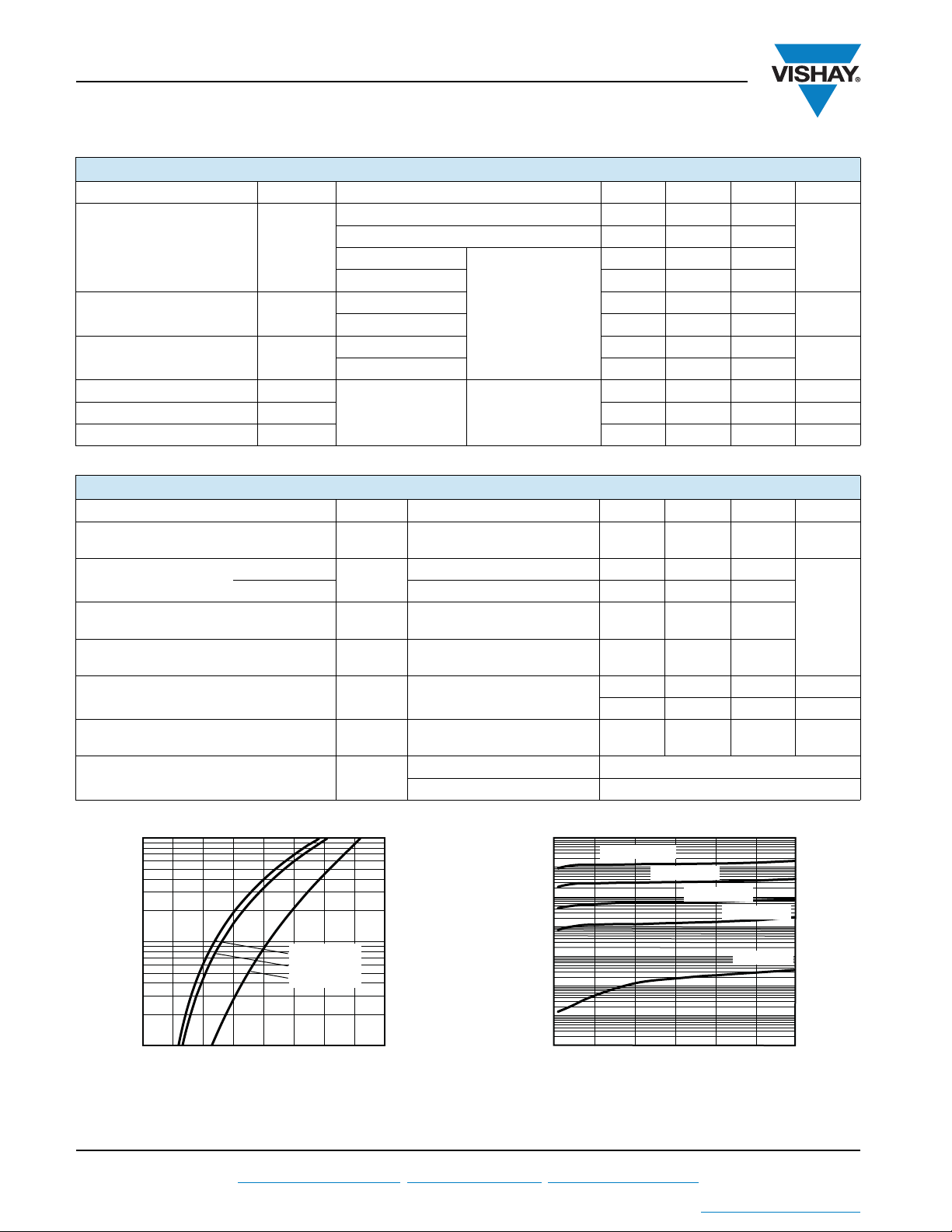
VF - Forward Voltage Drop (V)
I
F
- Instantaneous
Forward Current (A)
Vishay Semiconductors
Ultrafast Rectifier, 15 A FRED Pt
DYNAMIC RECOVERY CHARACTERISTICS (TC = 25 °C unless otherwise specified)
PARAMETER SYMBOL TEST CONDITIONS MIN. TYP. MAX. UNITS
IF = 1 A, dIF/dt = 100 A/μs, VR = 30 V - 18 22
= 15 A, dIF/dt = 100 A/μs, VR = 30 V - 20 32
I
Reverse recovery time t
Peak recovery current I
Reverse recovery charge Q
Reverse recovery time t
Peak recovery current I
Reverse recovery charge Q
rr
RRM
rr
rr
RRM
rr
F
T
= 25 °C
J
= 125 °C - 52 -
T
J
TJ = 25 °C - 2.4 -
T
= 125 °C - 5.1 -
J
= 15 A
I
F
dI
/dt = 200 A/μs
F
V
= 390 V
R
TJ = 25 °C - 25 -
T
= 125 °C - 150 -
J
= 15 A
I
F
TJ = 125 °C
dI
/dt = 800 A/μs
F
V
= 390 V
R
THERMAL - MECHANICAL SPECIFICATIONS
PARAMETER SYMBOL TEST CONDITIONS MIN. TYP. MAX. UNITS
Maximum junction and
storage temperature range
Thermal resistance,
junction to case
Thermal resistance,
junction to ambient per leg
Thermal resistance,
case to heatsink
Weight
Mounting torque
Marking device
(FULL-PAK) - 3.0 3.5
, T
T
J
Stg
R
thJC
Typical socket mount - - 70
R
thJA
Mounting surface, flat, smooth
R
thCS
and greased
Case style TO-220AC 15ETX06
Case style TO-220 FULL-PAK 15ETX06FP
®
-22-
-37-ns
-16- A
- 350 - nC
- 65 - 175 °C
-1.01.3
-0.5-
-2.0- g
-0.07- oz.
6.0
(5.0)
-
12
(10)
kgf · cm
(lbf · in)
ns
A
μC
°C/W
www.vishay.com For technical questions within your region, please contact one of the following: Document Number: 94006
2 DiodesAmericas@vishay.com
THE PRODUCT DESCRIBED HEREIN AND THIS DATASHEET ARE SUBJECT TO SPECIFIC DISCLAIMERS, SET FORTH AT
1000
100
10
1
0.1
0.01
- Reverse Current (µA)
R
I
0.001
0.0001
0 100 200 300 400 500 600
Fig. 1 - Typical Forward Voltage Drop Characteristics Fig. 2 - Typical Values of Reverse Current vs.
TJ = 175 °C
T
= 150 °C
J
= 125 °C
T
J
T
VR - Reverse Voltage (V)
Reverse Voltage
= 100 °C
J
T
= 25 °C
J
, DiodesAsia@vishay.com, DiodesEurope@vishay.com Revision: 28-Apr-11
This datasheet is subject to change without notice.
www.vishay.com/doc?91000
VS-15ETX06PbF, VS-15ETX06FPPbF
TJ = 25 °C
0
100 200 300 500 600400
1000
100
10
1
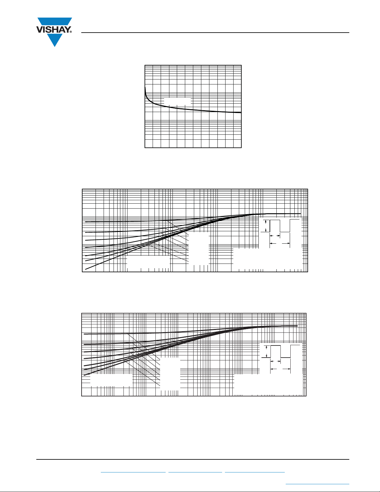
VR - Reverse Voltage (V)
C
T
- Junction Capacitance (pF)
0.01
0.1
1
10
0.00001 0.0001 0.001 0.01 0.1 1
t1 - Rectangular Pulse Duration (s)
Z
thJC
- Thermal Impedance (°C/W)
Single pulse
(thermal resistance)
.
.
P
DM
t
1
t
2
Notes:
1. Duty factor D = t
1/t2
2. Peak TJ = PDM x Z
thJC
+ T
C
D = 0.50
D = 0.20
D = 0.10
D = 0.05
D = 0.02
D = 0.01
0.01
0.1
1
10
0.00001 0.0001 0.001 0.01 0.1 1
t1 - Rectangular Pulse Duration (s)
Z
thJC
- Thermal Impedance (°C/W)
Single pulse
(thermal resistance)
.
.
P
DM
t
1
t
2
Notes:
1. Duty factor D = t
1/t2
2. Peak TJ = PDM x Z
thJC
+ T
C
10
100
D = 0.50
D = 0.20
D = 0.10
D = 0.05
D = 0.02
D = 0.01
Ultrafast Rectifier, 15 A FRED Pt
Fig. 3 - Typical Junction Capacitance vs. Reverse Voltage
®
Vishay Semiconductors
Fig. 4 - Maximum Thermal Impedance Z
Document Number: 94006 For technical questions within your region, please contact one of the following: www.vishay.com
Revision: 28-Apr-11 DiodesAmericas@vishay.com
THE PRODUCT DESCRIBED HEREIN AND THIS DATASHEET ARE SUBJECT TO SPECIFIC DISCLAIMERS, SET FORTH AT
Fig. 5 - Maximum Thermal Impedance Z
, DiodesAsia@vishay.com, DiodesEurope@vishay.com 3
This datasheet is subject to change without notice.
thJC
Characteristics (FULL-PAK)
thJC
Characteristics
www.vishay.com/doc?91000
 Loading...