

Page 1
Vishay Semiconductors
White LED in 3mm T 1 Waterclear Package
FEATURES
• High efficient InGaN technology
• Chromaticity coordinate categorized
according to CIE1931 per packing unit
• Typical chromaticity coordinates x = 0.33;
y = 0.33
• Typical color temperature 5500 K
•
ESD-withstand voltage up to 1 kV
19222
acc. to
JESD22-A114-B
• Small viewing angle, high luminous intensity
• Chip embedded in elastic resin, improved robustness against temperature cycle stress
• Lead (Pb)-free device
• RoHS compliant
VLHW490.
e2
DESCRIPTION
High Intensity LED with typical color coordinates
x = 0.33, y = 0.33 (typical color temperature 5500 k).
This LED emits white light with a high color rendering
index.
The emission spectrum is tuned for ideal white, without
APPLICATIONS
• Indicator and backlighting
• Indoor and outdoor message panels
• Alternative to incandescent lamps
• Marker lights
the impression of being blue shaded or "cold". The
package is a standard 3 mm.
The internal reflector is filled with a compound of TAG
phosphor and an elastic resin.
Therefore the chip is better protected against temperature cycle stress.
The phosphor converts the blue emission of the InGaN
chip partially to amber, which mixes with the remaining
blue to produce white.
PARTS TABLE
PART COLOR, LUMINOUS INTENSITY ANGLE OF HALF INTENSITY (± J) TECHNOLOGY
VLHW4900 White, I
VLHW4902 White, I
> 240 mcd 16° InGaN / TAG on SiC
V
= (430 to 2000) mcd 16° InGaN / TAG on SiC
V
Document Number 81248
Rev. 1.0, 07-Feb-06
www.vishay.com
1
Page 2
VLHW490.
Vishay Semiconductor
ABSOLUTE MAXIMUM RATINGS1) VLHW490.
PARAMETER TEST CONDITION SYMBOL VALUE UNIT
Reverse voltage
DC Forward current T
Surge forward current t
2)
≤ 50 °C I
amb
≤ 10 µs I
p
Power dissipation P
Junction temperature T
Operating temperature range T
Storage temperature range T
Soldering temperature t ≤ 5 s T
Thermal resistance junction/
ambient
1)
T
= 25 °C, unless otherwise specified
amb
2)
Driving the LED in reverse direction is suitable for short term application
OPTICAL AND ELECTRICAL CHARACTERISTICS1) WHITE VLHW490.
PARAMETER TEST CONDITION PART SYMBOL MIN TYP. MAX UNIT
Luminous intensity
2)
Luminous flux I
Chromaticity coordinate x acc.
to CIE 1931
Chromaticity coordinate y acc.
to CIE 1931
Angle of half intensity I
Forward voltage I
Reverse voltage I
Temperature coefficient of V
Temperature coefficient of I
1)
T
= 25 °C, unless otherwise specified
amb
2)
in one Packing Unit I
Vmin/IVmax
IF = 20 mA VLHW4900 I
VLHW4902 I
= 20 mA φ
F
I
= 20 mA x 0.33
F
= 20 mA y 0.33
I
F
= 20 mA ϕ ± 16 deg
F
= 20 mA V
F
= 10 µA V
R
= 20 mA TC
FIF
= 20 mA TC
VIF
≤ 0.5
R
V
R
F
FSM
V
amb
stg
sd
thJA
5V
30 mA
0.1 A
126 mW
j
100 °C
- 40 to + 100 °C
- 40 to + 100 °C
260 °C
400 K/W
V
V
V
F
R
V
I
240 500 mcd
430 2000 mcd
250 mlm
3.5 4.2 V
5V
- 4 mV/K
- 0.5 % / K
CHROMATICITY COORDINATE CLASSIFICATION
GROUP X Y
MIN MAX MIN MAX
3 0.280 0.325 0.210 0.340
4 0.305 0.350 0.260 0.390
5 0.330 0.375 0.310 0.440
LUMINOUS INTENSITY CLASSIFICATION
GROUP LIGHT INTENSITY [MCD]
STANDARD MIN MAX
Z 240 480
AA 320 640
BB 430 860
CC 575 1150
DD 750 1500
EE 1000 2000
www.vishay.com
2
Document Number 81248
Rev. 1.0, 07-Feb-06
Page 3
Vishay Semiconductors
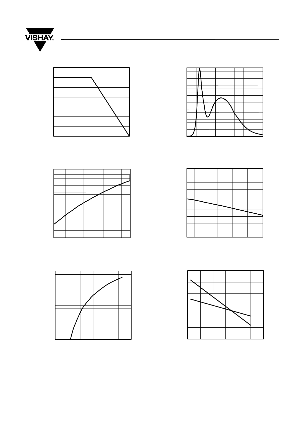
TYPICAL CHARACTERISTICS (TAMB = 25 °C UNLESS OTHERWISE SPECIFIED)
VLHW490.
35
30
25
20
15
10
F
I-Forward Current (mA)
5
0
020406080 100
T
-Ambient Temperature (°C)16804
amb
Figure 1. Forward Current vs. Ambient Temperature
10
1
0.1
Vrel
I - RelativeLuminous Intensity
0.01
1 10 100
I
16194
-Forward Current (mA)
F
Figure 2. Relative Luminous Intensity vs. Forward Current
100
90
80
70
60
50
40
30
20
V rel
10
I - RelativeLuminous Intensity
0
400 450 500 550 600 650 700 750 800
16196
λ
- Wavelength (nm)
Figure 4. Relative Intensity vs. Wavelength
2.0
1.8
1.6
1.4
1.2
1.0
0.8
0.6
0.4
Vrel
0.2
I - RelativeLuminous Intensity
0.0
0 1020 304050607080 90 100
T
16197
-Ambient Temperature (°C)
amb
Figure 5. Rel. Luminous Intensity vs. Ambient Temperature
100
10
F
I-Forward Current (mA)
1
2.0 2.5 3.0 3.5 4.0 4.5 5.0
Figure 3. Forward Current vs. Forward Voltage
Document Number 81248
Rev. 1.0, 07-Feb-06
0.345
White
0.340
X
0.335
0.330
Y
0.325
0.320
f - Chromaticity coordinate shift (x,y)
0.315
0605040302010
V
-Forward Voltage (V)16195
F
16198
I
-Forward Current (mA)
F
Figure 6. Chromaticity Coordinate Shift vs. Forward Current
www.vishay.com
3
Page 4

VLHW490.
Vishay Semiconductor
3.95
3.90
3.85
3.80
3.75
3.70
3.65
3.60
F
3.55
V -Forward Voltage (V)
3.50
3.45
0 1020 304050607080 90 100
16199
Figure 7. Forward Voltage vs. Ambient Temperature
T
-Ambient Temperature (°C)
amb
0°
10° 20°
30°
1.0
0.9
0.8
0.7
v rel
I - RelativeLuminous Intensity
0.4 0.2 0 0.2 0.4
0.6
Figure 8. Rel. Luminous Intensity vs. Angular Displacement
0.50
f
0.45
0.40
0.35
a
0.30
0.25
Coordinates of Colorgroups
0.20
0.20 0.25 0.30 0.35 0.40 0.45 0.50
16284
Figure 9. Coordinates of Colorgroups
c
b
3
Coordinates of Colorgroups
e
d
5
AD65
.
.
a = 20000 K
4
b = 10000 K
c = 7000 K
d = 6000 K
e = 5000 K
f = 4000 K
40°
50°
60°
70°
80°
0.6
www.vishay.com
4
Document Number 81248
Rev. 1.0, 07-Feb-06
Page 5

PACKAGE DIMENSIONS IN MM
VLHW490.
Vishay Semiconductors
16811
BARCODE-PRODUCT-LABEL
106
A
B C D
F G
E
H
VISHAY
37
19937
A) Type of component
B) Manufacturing plant
C) SEL - Selection Code (Bin):
e.g.: Z = Code for Luminous Intensity Group
3 = Code for Chromaticity Coordinate
D) Date Code year/week
E) Day Code (e.g. 1: Monday)
F) Batch No.
G) Total quantity
H) Company Code
Document Number 81248
Rev. 1.0, 07-Feb-06
www.vishay.com
5
Page 6

VLHW490.
Vishay Semiconductor
Ozone Depleting Substances Policy Statement
It is the policy of Vishay Semiconductor GmbH to
1. Meet all present and future national and international statutory requirements.
2. Regularly and continuously improve the performance of our products, processes, distribution and operating
systems with respect to their impact on the health and safety of our employees and the public, as well as their
impact on the environment.
It is particular concern to control or eliminate releases of those substances into the atmosphere which are known as
ozone depleting substances (ODSs).
The Montreal Protocol (1987) and its London Amendments (1990) intend to severely restrict the use of ODSs and
forbid their use within the next ten years. Various national and international initiatives are pressing for an earlier ban
on these substances.
Vishay Semiconductor GmbH has been able to use its policy of continuous improvements to eliminate the use of
ODSs listed in the following documents.
1. Annex A, B and list of transitional substances of the Montreal Protocol and the London Amendments respectively
2. Class I and II ozone depleting substances in the Clean Air Act Amendments of 1990 by the Environmental
Protection Agency (EPA) in the USA
3. Council Decision 88/540/EEC and 91/690/EEC Annex A, B and C (transitional substances) respectively.
Vishay Semiconductor GmbH can certify that our semiconductors are not manufactured with ozone depleting
substances and do not contain such substances.
We reserve the right to make changes to improve technical design
and may do so without further notice.
Parameters can vary in different applications. All operating parameters must be validated for each customer
application by the customer. Should the buyer use Vishay Semiconductors products for any unintended or
unauthorized application, the buyer shall indemnify Vishay Semiconductors against all claims, costs,
damages, and expenses, arising out of, directly or indirectly, any claim of personal damage, injury or death
associated with such unintended or unauthorized use.
Vishay Semiconductor GmbH, P.O.B. 3535, D-74025 Heilbronn, Germany
www.vishay.com
6
Document Number 81248
Rev. 1.0, 07-Feb-06
Page 7

Legal Disclaimer Notice
Vishay
Document Number: 91000 www.vishay.com
Revision: 08-Apr-05 1
Notice
Specifications of the products displayed herein are subject to change without notice. Vishay Intertechnology, Inc.,
or anyone on its behalf, assumes no responsibility or liability for any errors or inaccuracies.
Information contained herein is intended to provide a product description only. No license, express or implied, by
estoppel or otherwise, to any intellectual property rights is granted by this document. Except as provided in Vishay's
terms and conditions of sale for such products, Vishay assumes no liability whatsoever, and disclaims any express
or implied warranty, relating to sale and/or use of Vishay products including liability or warranties relating to fitness
for a particular purpose, merchantability, or infringement of any patent, copyright, or other intellectual property right.
The products shown herein are not designed for use in medical, life-saving, or life-sustaining applications.
Customers using or selling these products for use in such applications do so at their own risk and agree to fully
indemnify Vishay for any damages resulting from such improper use or sale.
 Loading...