

Page 1

Fig.1 Component outlines
030/031 AS
041/043 ASH
021 ASM
117 ASD
high
voltage
smaller
dimensions
RoHS
COMPLIANT
030/031 AS
Vishay BCcomponents
Aluminum Capacitors
Axial Standard
FEATURES
Polarized aluminum electrolytic capacitors,
non-solid electrolyte
Axial leads, cylindrical aluminum case,
insulated with a blue sleeve
Taped version available for automatic insertion
Charge and discharge proof
Useful life: 3000 h at 85 °C
(case Ø D = 3.3 mm: 1500 h)
Standard dimensions
Lead (Pb)-free versions are RoHS compliant
Compliant to RoHS directive 2002/95/EC
QUICK REFERENCE DATA
DESCRIPTION VALUE
Nominal case sizes
(Ø D x L in mm)
Rated capacitance range, C
Tolerance on C
Rated voltage, U
Category temperature range - 40 °C to + 85 °C
Endurance test at 85 °C 1000 h 2000 h
Useful life at 85 °C 1500 h 3000 h
Useful life at 40 °C,
1.4 x I
R
Shelf life at 0 V, 85 °C 500 h
Based on sectional specification IEC 60384-4/EN130 300
Climatic category IEC 60068 40/085/56
R
R
applied
R
3.3 x 11
0.47 µF to 1000 µF
- 10 % to + 50 %
6.3 V to 100 V
40 000 h 80 000 h
4.5 x 10
to 10 x 25
APPLICATIONS
General purpose and industrial, automotive,
telecommunication, audio-video
Coupling, decoupling, timing, smoothing, filtering,
buffering in SMPS
Boards with restricted mounting height, vibration and
shock resistant
MARKING
The capacitors are marked (where possible) with the
following information:
Rated capacitance (in µF)
Tolerance on rated capacitance, code letter in accordance
with IEC 60062 (T for - 10 % to + 50 %)
Rated voltage (in V)
Date code in accordance with IEC 60062
Code factory of origin
Name of manufacturer
Negative terminal identification
Series number (030 or 031)
Document Number: 28327 For technical questions, contact: aluminumcaps1@vishay.com
Revision: 02-Sep-10 179
www.vishay.com
Page 2
030/031 AS
63.5 ± 1.5
Ø D
Ø d
L
F
+
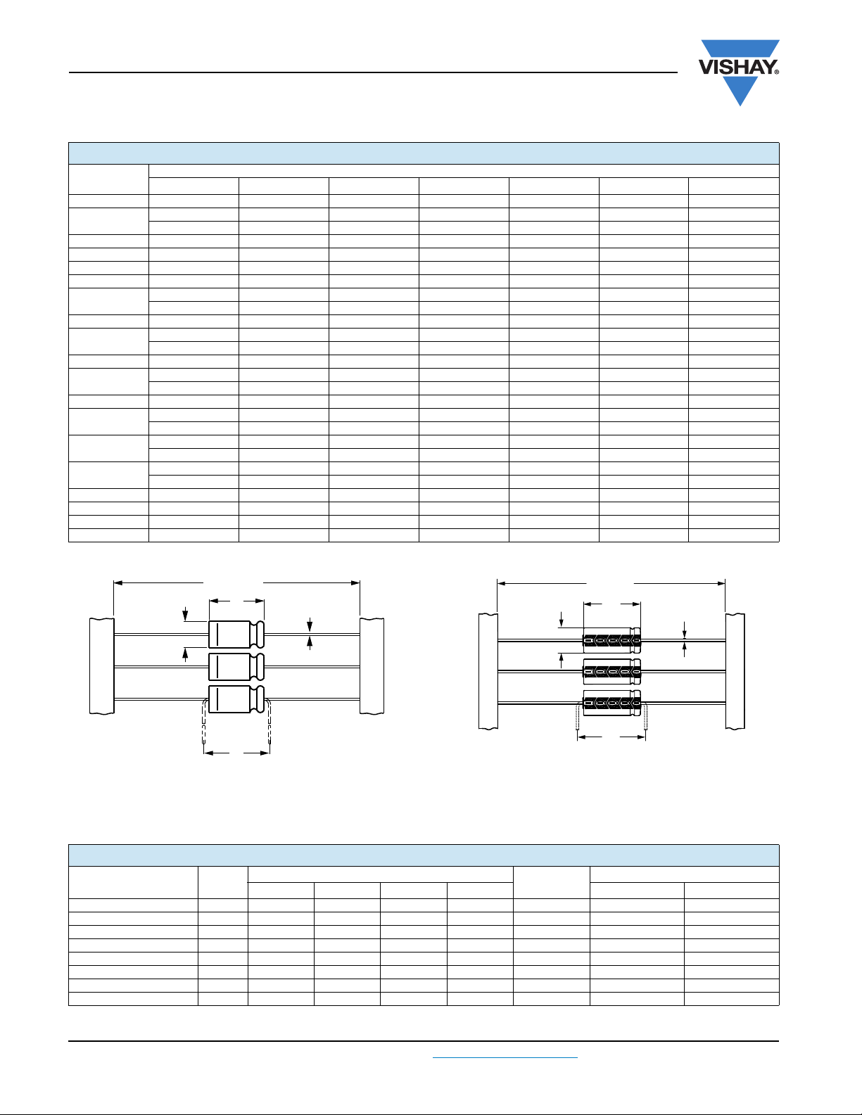
Form BR: Taped on reel
Form BA: Taped in box (ammopack)
Case Ø D x L = 4.5 mm x 10 mm to 8 mm x 11 mm
Fig.2 Forms BA and BR
Vishay BCcomponents
Aluminum Capacitors
Axial Standard
SELECTION CHART FOR CR, UR AND RELEVANT NOMINAL CASE SIZES (Ø D x L in mm)
(V)
C
R
(µF)
0.47 - - - - - - 4.5 x 10
1.0
2.2 - - - - 3.3 x 11 4.5 x 10 4.5 x 10
3.3 - - - - - 4.5 x 10 4.5 x 10
4.7 - - 3.3 x 11 - - 4.5 x 10 6 x 10
6.8 - - - - - 4.5 x 10 6 x 10
10
15 - - - - 4.5 x 10 6 x 10 -
22
33 - - 4.5 x 10 - 6 x 10 - 10 x 18
47
68 4.5 x 10 - 6 x 10 - - 10 x 18 -
100
150
220
330 - 8 x 18 10 x 18 10 x 25 - - 470 8 x 18 10 x 18 10 x 25 - - - 680 10 x 18 10 x 25 - - - - -
1000 10 x 25 - - - - - -
6.3 10 16 25 40 63 100
-----4.5x104.5x10
-----3.3x11-
3.3 x 11 - - 4.5 x 10 4.5 x 10 6 x 10 8 x 11
------6.5x18
- - - 4.5x10 6x10 8x11 8x18
-----6.5x18-
- 4.5 x 10 - 6 x 10 8 x 11 8 x 18 10 x 25
----6.5x18--
- 6 x 10 - 8 x 11 8 x 18 10 x 25 -
---6.5x18---
6 x 10 - 8 x 11 8 x 18 10 x 18 - -
--6.5x18----
- 8x11 8x18 10x18 10x25 - -
-6.5x18-----
DIMENSIONS in millimeters AND AVAILABLE FORMS
U
R
Tab l e 1
AXIAL; DIMENSIONS in millimeters, MASS AND PACKAGING QUANTITIES
NOMINAL CASE SIZE
Note
Detailed tape dimensions see section ‘PACKAGING’.
www.vishay.com For technical questions, contact: aluminumcaps1@vishay.com Document Number: 28327
180 Revision: 02-Sep-10
Ø DxL
3.3 x 11 1 0.6 3.5 12 17.5 0.35 1000 4000
4.5 x 10 2 0.6 5.0 10.5 15 0.5 1000 3000
6 x 10 3 0.6 6.3 10.5 15 0.7 1000 1000
8 x 11 5a 0.6 8.5 11.5 15 1.1 500 500
6.5 x 18 4 0.8 6.9 18.5 25 1.3 1000 1000
8 x 18 5 0.8 8.5 18.5 25 1.7 500 500
10 x 18 6 0.8 10.5 18.5 25 2.5 500 500
10 x 25 7 0.8 10.5 25.0 30 3.3 500 500
CASE
CODE
AXIAL FORM BA and BR
Ø d Ø D
max.
L
max.
73 ± 1.6
Ø D
Form BR: Taped on reel
Case Ø D x L = 6.5 mm x 18 mm to 15 mm x 30 mm
Form BA: Taped in box (ammopack)
Case Ø D x L = 6.5 mm x 18 mm to 10 mm x 25 mm
L
Ø d
F
Fig.3 Forms BA and BR
MASS
F
min.
(g)
PACKAGING QUANTITIES
FORM BA FORM BR
Page 3

030/031 AS
Aluminum Capacitors
Vishay BCcomponents
Axial Standard
ELECTRICAL DATA
SYMBOL DESCRIPTION
C
R
I
R
I
L1
I
L5
tan max. dissipation factor at 100 Hz
ESR
Z max. impedance at 10 kHz
Note
Unless otherwise specified, all electrical values in table 2 apply at
T
amb
Tab l e 2
rated capacitance at 100 Hz, tolerance - 10 % to
+ 50 %
rated RMS ripple current at 100 Hz, 85 °C
max. leakage current after 1 min at U
max. leakage current after 5 min at U
equivalent series resistance at 100 Hz
(calculated from tan
= 20 °C, P = 86 kPa to 106 kPa, RH = 45 % to 75 %.
max.
and CR)
R
R
ELECTRICAL DATA AND ORDERING INFORMATION
R
NOMINAL
CASE SIZE
Ø D x L
(mm)
CASE
CODE
U
(V)
6.3
10
16
25
Document Number: 28327 For technical questions, contact: aluminumcaps1@vishay.com
Revision: 02-Sep-10 181
C
R
100 Hz
(µF)
10 3.3 x 11 1 15 5 5.1 0.30 47.8 20.0 03023109E3 03033109E3
68 4.5 x 10 2 75 22 5.9 0.25 5.86 2.90 03023689E3 03033689E3
150 6 x 10 3 120 10 6.9 0.25 2.66 1.30 03023151E3 03033151E3
470 8 x 18 5 330 22 11 0.25 0.85 0.43 03123471E3 03133471E3
680 10 x 18 6 430 30 14 0.25 0.59 0.29 03123681E3 03133681E3
1000 10 x 25 7 560 42 18 0.25 0.40 0.20 03123102E3 03133102E3
47 4.5 x 10 2 70 24 5.9 0.20 6.78 3.40 03024479E3 03034479E3
100 6 x 10 3 110 10 7.0 0.20 3.19 1.60 03024101E3 03034101E3
220 8 x 11 5a 210 18 9.4 0.20 1.45 0.73 03024221E3 03034221E3
220 6.5 x 18 4 210 18 9.4 0.20 1.45 0.73 03124221E3 03134221E3
330 8 x 18 5 310 24 12 0.20 0.97 0.48 03124331E3 03134331E3
470 10 x 18 6 410 33 14 0.20 0.68 0.34 03124471E3 03134471E3
680 10 x 25 7 510 45 19 0.20 0.47 0.24 03124681E3 03134681E3
4.7 3.3 x 11 1 15 5 5.1 0.20 67.8 26.0 03025478E3 03035478E3
33 4.5 x 10 2 65 27 6.1 0.16 7.72 3.60 03025339E3 03035339E3
68 6 x 10 3 110 11 7.2 0.16 3.75 1.80 03025689E3 03035689E3
150 8 x 11 5a 200 19 9.8 0.16 1.70 0.80 03025151E3 03035151E3
150 6.5 x 18 4 200 19 9.8 0.16 1.70 0.80 03125151E3 03135151E3
220 8 x 18 5 270 26 12 0.16 1.16 0.55 03125221E3 03135221E3
330 10 x 18 6 410 36 16 0.16 0.78 0.36 03125331E3 03135331E3
470 10 x 25 7 480 49 20 0.16 0.55 0.26 03125471E3 03135471E3
10 4.5 x 10 2 50 13 5.5 0.14 22.3 9.00 03026109E3 03036109E3
22 4.5 x 10 2 60 28 6.1 0.14
47 6 x 10 3 100 12 7.4 0.14 4.80 1.90 03026479E3 03036479E3
100 8 x 11 5a 160 19 10 0.14 2.23 0.90 03026101E3 03036101E3
100 6.5 x 18 4 160 19 10 0.14 2.23 0.90 03126101E3 03136101E3
150 8 x 18 5 240 27 13 0.14 1.49 0.60 03126151E3 03136151E3
220 10 x 18 6 350 37 16 0.14 1.02 0.41 03126221E3 03136221E3
330 10 x 25 7 460 54 22 0.14 0.68 0.27 03126331E3 03136331E3
I
R
100 Hz
85 C
(mA)
I
L1
1min
(µA)
I
5min
(µA)
ORDERING EXAMPLE
Electrolytic capacitor 031 series
330 µF/10 V; - 10 %/+ 50 %
Nominal case size:Ø 8 mm x 18 mm; Form BA
Ordering code: MAL203134331E3
Former 12NC: 2222 031 34331
L5
tan
100 Hz
ESR
100 Hz
()
10.2
Z
10 kHz
()
4.10 03026229E3 03036229E3
TAPED ON
REEL
FORM BR
ORDERING CODE
MAL2..........
TAPED IN BOX
FORM BA
www.vishay.com
Page 4

030/031 AS
Vishay BCcomponents
Aluminum Capacitors
Axial Standard
ELECTRICAL DATA AND ORDERING INFORMATION
U
(V)
40
63
100
R
NOMINAL
CASE SIZE
Ø D x L
(mm)
CASE
CODE
C
R
100 Hz
(µF)
2.2 3.3 x 11 1 15 5 5.1 0.15
10 4.5 x 10 2 50 20 5.8 0.11
15 4.5 x 10 2 55 30 6.2 0.11 11.7
22 6 x 10 3 75 9 6.8 0.11 8.00 3.20 03027229E3 03037229E3
33 6 x 10 3 95 12 7.7 0.11 5.31 2.10 03027339E3 03037339E3
47 8 x 11 5a 150 16 8.8 0.11 3.73 1.50 03027479E3 03037479E3
47 6.5 x 18 4 150 16 8.8 0.11 3.73 1.50 03127479E3 03137479E3
100 8 x 18 5 220 28 13 0.11 1.75 0.70 03127101E3 03137101E3
150 10 x 18 6 300 40 17 0.11 1.17 0.47 03127151E3 03137151E3
220 10 x 25 7 430 57 23 0.11 0.80 0.32 03127221E3 03137221E3
1.0 3.3 x 11 1 10 5 5.1 0.12 191 55.0 03090067E3 03090068E3
1.0 4.5 x 10 2 13 5 5.1 0.09 143 55.0 03028108E3 03038108E3
2.2 4.5 x 10 2 25 7 5.3 0.09 65.2 25.0 03028228E3 03038228E3
3.3 4.5 x 10 2 35 11 5.4 0.09 46.5 17.0 03028338E3 03038338E3
4.7 4.5 x 10 2 40 15 5.6 0.09 30.5 12.0 03028478E3 03038478E3
6.8 4.5 x 10 2 46 22 5.9 0.09 21.1 8.10 03028688E3 03038688E3
10 6 x 10 3 70 7 6.3 0.08 12.8 5.50 03028109E3 03038109E3
15 6 x 10 3 79 10 6.9 0.08 8.50 3.70 03028159E3 03038159E3
22 8 x 11 5a 110 13 7.8 0.08 5.79 2.50 03028229E3 03038229E3
22 6.5 x 18 4 110 13 7.8 0.08 5.79 2.50 03128229E3 03138229E3
47 8 x 18 5 190 22 11 0.08 2.71 1.20 03128479E3 03138479E3
68 10 x 18 6 250 30 14 0.08 1.88 0.81 03128689E3 03138689E3
100 10 x 25 7 300 42 18 0.08 1.28 0.55 03128101E3 03138101E3
0.47 4.5 x 10 2 9 5 4.3 0.08 271 96.0 03029477E3 03039477E3
1.0 4.5 x 10 2 20 5 4.6 0.08 128 45.0 03029108E3 03039108E3
2.2 4.5 x 10 2 30 11 5.3 0.08 57.9 21.0 03029228E3 03039228E3
3.3 4.5 x 10 2 40 17 6.0 0.08 38.6 14.0 03029338E3 03039338E3
4.7 6 x 10 3 50 13 6.8 0.07 23.7 9.60 03029478E3 03039478E3
6.8 6 x 10 3 70 18 8.0 0.07 16.4 6.60 03029688E3 03039688E3
10 8 x 11 5a 90 24 10 0.07 11.2 4.50 03029109E3 03039109E3
10 6.5 x 18 4 90 24 10 0.07 11.2 4.50 03129109E3 03139109E3
22 8 x 18 5 120 48 18 0.07 5.07 2.10 03129229E3 03139229E3
33 10 x 18 6 200 70 24 0.07 3.38 1.40 03129339E3 03139339E3
47 10 x 25 7 260 98 33 0.07 2.37 0.96 03129479E3 03139479E3
I
R
100 Hz
85 C
(mA)
I
L1
1min
(µA)
I
L5
5min
(µA)
tan
100 Hz
ESR
100 Hz
()
109
17.6
ORDERING CODE
REEL
MAL2..........
TAPED IN BOX
FORM BA
Z
10 kHz
()
32.0 03027228E3 03037228E3
7.00 03027109E3 03037109E3
4.70
TAPED ON
FORM BR
03027159E3 03037159E3
www.vishay.com For technical questions, contact: aluminumcaps1@vishay.com Document Number: 28327
182 Revision: 02-Sep-10
Page 5

030/031 AS
T
amb
(°C)
C
0
= capacitance at 20 °C, 100 Hz
7
6
5
4
3
2
1
1.2
1.1
1.0
0.9
0.8
0.7
0.6
- 60 - 40 - 20 0 20 40 60 80
C
C
0
Fig.4 Typical multiplier of capacitance as a function
of ambient temperature
1
2
Curve 1: 6.3 V
Curve 2: 10 V
Curve 3: 16 V
Curve 4: 25 V
Curve 5: 40 V
Curve 6: 63 V
Curve 7: 100 V
1.05
1.00
0.95
0.90
0.85
0.75
10 10
2
103 104
C
C
0
T
amb
(°C)
Fig.5 Typical multiplier of capacitance as a
function of frequency
7
6
5
4
3
2
1
1
7
C
0
= capacitance at 20 °C, 100 Hz
Curve 1: 6.3 V
Curve 2: 10 V
Curve 3: 16 V
Curve 4: 25 V
Curve 5: 40 V
Curve 6: 63 V
Curve 7: 100 V
Aluminum Capacitors
Vishay BCcomponents
Axial Standard
ADDITIONAL ELECTRICAL DATA
PARAMETER CONDITIONS VALUE
Volt ag e
Surge voltage U
Reverse voltage U
Current
Leakage current After 1 min at U
:
R
Case Ø D x L = 3.3 mm x 11mm and 4.5 mm x 10 mm I
Case Ø D x L = 6 mm x 10 mm to 10 mm x 25 mm I
U
=100V IL1 = 0.02 CRxUR+4µA
R
After 5 min:
=6.3 Vto63V IL5 0.002 CRxUR+5µA
U
R
=100V IL5 0.006 CRxUR+4µA
U
R
Inductance
Equivalent series
inductance (ESL)
Case Ø D x L mm:
3.3 x 11 typ. 11 nH
4.5 x 10 typ. 10 nH
6 x 10 typ. 22 nH
8 x 11 typ. 85 nH
6.5 x 18 typ. 25 nH
8 x 18 typ. 40 nH
10 x 18 typ. 61 nH
10 x 25 typ. 38 nH
Resistance
Equivalent series
resistance (ESR)
Calculated from tan
and CR (see table 2) ESR = tan /2 f C
max.
1.15 x U
s
1V
rev
0.05 CRxURor 5 µA, whichever is greater
L1
for CV 1000: 0.01 CRxURor 1 µA, whichever is
L1
I
for CV 1000: 0.006 CRxUR+4µA
L1
R
R
CAPACITANCE (C)
Document Number: 28327 For technical questions, contact: aluminumcaps1@vishay.com
Revision: 02-Sep-10 183
www.vishay.com
Page 6

030/031 AS
T
amb
(°C)
ESR
0
= capacitance at 20 °C, 100 Hz
- 60 - 40 - 20 0 20 40 60 80 100 120
Fig.6 Typical multiplier of ESR as a function
of ambient temperature
30
20
10
0.3
ESR
ESR
0
1
2
3
1
3
2
Curve 1: 6.3 V
Curve 2: 63 V
Curve 3: 100 V
T
amb
20 °C
Fig.8 Typical impedance as a function of frequency
10
4
10
3
10
2
10
1
10
-1
102 103 104 105 10
6
Z
(Ω)
Curve 1: 1 µF, 63 V, 3.3 x 11 mm
Curve 2: 2.2 µF, 40 V, 3.3 x 11 mm
Curve 3: 4.7 µF,16 V, 3.3 x 11 mm
Curve 4: 10 µF, 25 V, 4.5 x 11 mm
Curve 5: 22 µF, 25 V, 4.5 x 11 mm
Curve 6: 47 µF, 25 V, 6 x 11 mm
Curve 7: 100 µF, 25 V, 6.5 x 11 mm
Curve 8: 220 µF, 10 V, 6.5 x 11 mm
1
4
6
7
8
5
3
2
Vishay BCcomponents
Aluminum Capacitors
Axial Standard
EQUIVALENT SERIES RESISTANCE (ESR)
2
ESR
ESR
0
1
0
10
= capacitance at 20 °C, 100 Hz
ESR
0
IMPEDANCE (Z
)
Tab l e 3
IMPEDANCE VS. CAPACITANCE VALUES AT 10 kHz
T
amb
6.3 V 10 V 16 V 25 V 40 V 63 V 100 V
+ 20 °C 200 160 120 90 70 55 45
- 25 °C 1200 750 560 400 300 180 130
- 40 °C 3200 2000 1500 1100 900 500 350
Z x CR (x µF)
2
1
3
2
10
Fig.7 Typical multiplier of ESR as a function
of frequency
10
1
3
2
(°C)
4
10
3
T
amb
www.vishay.com For technical questions, contact: aluminumcaps1@vishay.com Document Number: 28327
184 Revision: 02-Sep-10
3
10
Z
(Ω)
10
1
10
10
1
1
2
3
4
5
6
-1
-2
102 103 104 105 10
Curve 1: 22 µF, 63 V, 8 x 11 mm
Curve 2: 47 µF, 40 V, 8 x 11 mm
Curve 3: 150 µF, 25 V, 8 x 18 mm
Curve 4: 330 µF, 16 V, 10 x 18 mm
Curve 5: 470 µF, 16 V, 10 x 25 mm
Curve 6: 1000 µF, 6.3 V, 10 x 25 mm
T
20 °C
amb
6
Fig.9 Typical impedance as a function of frequency
Page 7

030/031 AS
3.3
3.2
3.0
2.8
2.6
2.4
2.2
2.0
1.8
1.6
1.4
1.2
1.0
0.8
0.5
0.0
3.1
40 50 60 70 80 90 100
T
amb
(°C)
CCC205
lifetime multiplier
(1)
70
50
4.0
6 .0
2.0
1.5
30
15
10
3.0
20
1.0
I
A
I
R
CCC205
IA = actual ripple current at 100 Hz
I
R
= rated ripple current at 100 Hz, 85 °C
(1)
Useful life at 85 °C and IR applied:
case Ø D x L = 3.3 x 11 mm: 1500 h
case Ø D x L = 4.5 x 10 mm to 10 mm x 25 mm:
3000 h
Fig.10 Multiplier of useful life as a function of ambient temperature and ripple current load
Aluminum Capacitors
RIPPLE CURRENT AND USEFUL LIFE
Vishay BCcomponents
Axial Standard
Tab l e 4
MULTIPLIER OF RIPPLE CURRENT (IR) AS A FUNCTION OF FREQUENCY
FREQUENCY
(Hz)
50 0.95 0.90 0.85
100 1.00 1.00 1.00
300 1.07 1.12 1.20
1000 1.12 1.20 1.30
3000 1.15 1.25 1.35
10 000 1.20 1.30 1.40
Document Number: 28327 For technical questions, contact: aluminumcaps1@vishay.com
Revision: 02-Sep-10 185
www.vishay.com
I
MULTIPLIER
R
U
= 6.3 V to 10 V UR= 16 V to 25 V UR= 40 V to 100 V
R
Page 8

030/031 AS
Vishay BCcomponents
Aluminum Capacitors
Tab l e 5
TEST PROCEDURES AND REQUIREMENTS
TEST
NAME OF TEST REFERENCE
Case Ø D x L = 3.3 mm x 11 mm
Endurance IEC 384-4/
EN130300
subclause 4.13
Useful life CECC 30301
subclause 1.8.1
Shelf life
(storage at
high temperature)
IEC 384-4/
EN130300
subclause 4.17
Case Ø D L = 4.5 mm x 10 mm to 10 mm x 25 mm
Endurance IEC 384-4/
EN130300
subclause 4.13
Useful life CECC 30301
subclause 1.8.1
Shelf life
(storage at
high temperature)
IEC 384-4/
EN130300
subclause 4.17
T
=85 °C; UR applied;
amb
1000 h
T
=85°C; UR and IR applied;
amb
1500 h
T
= 85 °C; no voltage applied;
amb
500 h
After test: U
to 48 h before measurement
T
=85°C; UR applied;
amb
2000 h
T
=85°C; UR and IR applied;
amb
3000 h
T
= 85 °C; no voltage applied;
amb
500 h
After test: U
24 h to 48 h before measurement
Axial Standard
PROCEDURE
(quick reference)
to be applied for 30 min, 24 h
R
to be applied for 30 min,
R
REQUIREMENTS
C/C: ± 20 %
tan 2 x spec. limit
Z 3 x spec. limit
spec. limit
I
L
C/C: ± 50 %
tan 3 x spec. limit
Z 3 x spec. limit
spec. limit
I
L
no short or open circuit
total failure percentage: 3 %
C/C, tan , Z:
for requirements
see ‘Endurance test’ above
I
2 x spec. limit
L
UR 6.3 V; C/C: + 15 %/- 30 %
6.3 V; C/C: ± 15 %
U
R
tan 1.3 x spec. limit
Z 2 x spec. limit
spec. limit
I
L
UR 6.3 V; C/C: + 45 %/- 50 %
6.3 V; C/C: ± 45 %
U
R
tan 3 x spec. limit
Z 3 x spec. limit
spec. limit
I
L
no short or open circuit
total failure percentage: 1 %
C/C, tan ,Z:
for requirements
see ‘Endurance test’ above
I
2 x spec. limit
L
www.vishay.com For technical questions, contact: aluminumcaps1@vishay.com Document Number: 28327
186 Revision: 02-Sep-10
Page 9

Legal Disclaimer Notice
Vishay
Disclaimer
All product specifications and data are subject to change without notice.
Vishay Intertechnology, Inc., its affiliates, agents, and employees, and all persons acting on its or their behalf
(collectively, “Vishay”), disclaim any and all liability for any errors, inaccuracies or incompleteness contained herein
or in any other disclosure relating to any product.
Vishay disclaims any and all liability arising out of the use or application of any product described herein or of any
information provided herein to the maximum extent permitted by law. The product specifications do not expand or
otherwise modify Vishay’s terms and conditions of purchase, including but not limited to the warranty expressed
therein, which apply to these products.
No license, express or implied, by estoppel or otherwise, to any intellectual property rights is granted by this
document or by any conduct of Vishay.
The products shown herein are not designed for use in medical, life-saving, or life-sustaining applications unless
otherwise expressly indicated. Customers using or selling Vishay products not expressly indicated for use in such
applications do so entirely at their own risk and agree to fully indemnify Vishay for any damages arising or resulting
from such use or sale. Please contact authorized Vishay personnel to obtain written terms and conditions regarding
products designed for such applications.
Product names and markings noted herein may be trademarks of their respective owners.
Document Number: 91000 www.vishay.com
Revision: 18-Jul-08 1
 Loading...