

Page 1
021 ASM
021 ASM
lower
CV-values
117 ASD
138 AML
longer life
041/043 ASH
high voltage
105
°C
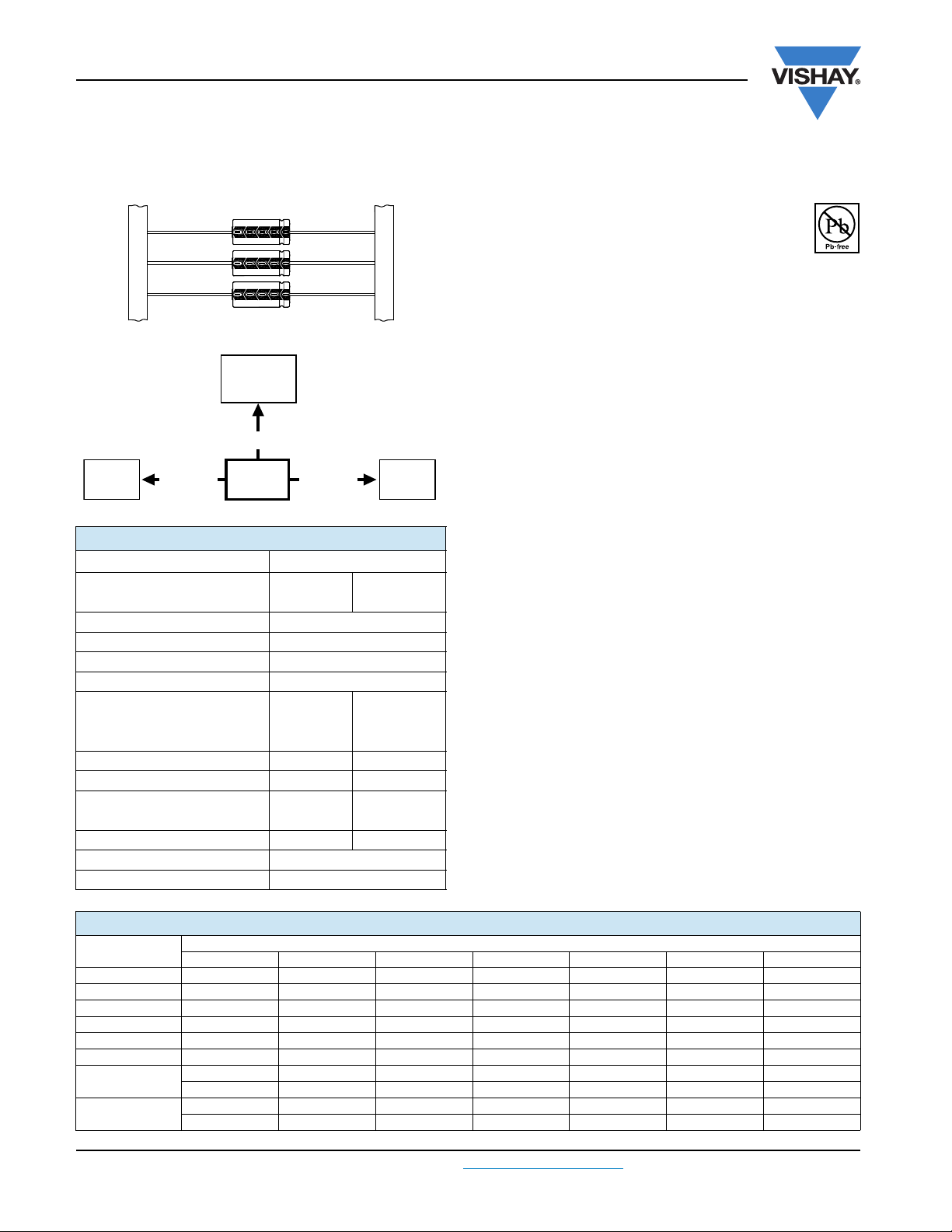
Vishay BCcomponents
Aluminum Capacitors
Axial Standard Miniature
Fig.1 Component outlines
QUICK REFERENCE DATA
DESCRIPTION VALUE
Nominal case sizes
(ØD x L in mm)
Rated capacitance range, C
Tolerance on C
Rated voltage range, U
Category temperature range - 40 °C to + 85 C
Endurance test at 85 °C:
= 6.3 V to 25 V 1000 h
U
R
U
= 40 V to 100 V
R
Endurance test at 105 °C - 2000 h
Useful life at 85 °C 2500 h 8000 h
Useful life at 40 C,
1.4 x IR applied
Shelf life at 0 V, 85 C 500 h 500 h
Based on sectional specification IEC 60384-4/EN130300
Climatic category IEC 60068 40/085/56
R
R
R
4.5 x 10
to 10 x 25
0.47 µF to 15 000 µF
6.3 V to 100 V
2000 h 5000 h
70 000 h 200 000 h
10 x 30
to 21 x 38
± 20 %
5000 h
FEATURES
Polarized aluminum electrolytic capacitors,
non-solid electrolyte
Axial leads, cylindrical aluminum case,
insulated with a blue sleeve
RoHS
COMPLIANT
Mounting ring version not available in insulated form
Taped versions up to case Ø 15 mm x 30 mm available for
automatic insertion
Charge and discharge proof
Miniaturized, high CV-product per unit volume
Compliant to RoHS directive 2002/95/EC
APPLICATIONS
General purpose, industrial, automotive, audio-video
Coupling, decoupling, smoothing, filtering, buffering
Portable and mobile equipment (small size, low mass)
Low mounting height boards, vibration and shock resistant
MARKING
The capacitors are marked (where possible) with the
following information:
Rated capacitance (in µF)
Tolerance on rated capacitance, code letter in accordance
with IEC 60062 (M for ± 20 %)
Rated voltage (in V)
Upper category temperature (85 °C)
Date code in accordance with IEC 60062
Code for factory of origin
Name of manufacturer
Negative terminal identification
Series number (021)
SELECTION CHART FOR CR, UR AND RELEVANT NOMINAL CASE SIZES (ØDxL in mm)
C
R
(µF)
0.47 - - - - - 4.5 x 10 -
1.0 - - - - - 4.5 x 10 4.5 x 10
2.2 - - - - - 4.5 x 10 4.5 x 10
3.3 - - - - - 4.5 x 10 -
4.7 - - - - - 4.5 x 10 4.5 x 10
10 - - - - - 4.5 x 10 6 x 10
15
22
www.vishay.com For technical questions, contact: aluminumcaps1@vishay.com
172 Revision: 06-Sep-10
6.31016254063100
- - - - - 4.5 x 10 8 x 11
------6.5x18
- - - - 4.5 x 10 6 x 10 8 x 11
------6.5 x18
U
(V)
R
Document Number: 28325
Page 2
021 ASM
63.5 ± 1.5
Ø D
Ø d
L
F
+
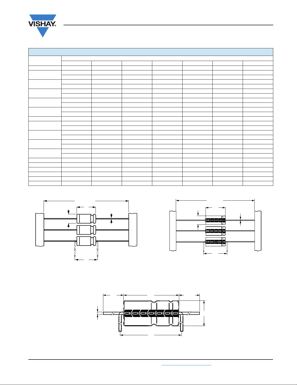
Form BR: Taped on reel
Form BA: Taped in box (ammopack)
Case Ø D x L = 4.5 mm x 10 mm to 8 mm x 11 mm
Fig.2 Forms BA and BR
73 ± 1.6
Ø D
Ø d
L
F
Form BR: Taped on reel
Case Ø D x L = 6.5 mm x 18 mm to 15 mm x 30 mm
Form BA: Taped in box (ammopack)
Case Ø D x L = 6.5 mm x 18 mm to 10 mm x 25 mm
Fig.3 Forms BA and BR
Form AA: Axial in box
Case Ø D x L = 10 mm x 30 mm to 21 mm x 38 mm
Fig.4 Form AA
33 ± 1
Ø D
Ø d
I
L
F
Aluminum Capacitors
Vishay BCcomponents
Axial Standard Miniature
SELECTION CHART FOR CR, UR AND RELEVANT NOMINAL CASE SIZES (ØDxL in mm)
C
R
(µF)
6.3 10 16 25 40 63 100
33 - - - - - 6 x 10 6.5 x 18
47
68
100
150
220
- - - 4.5x10 6x10 8x11 8x18
-----6.5x18-
- - 4.5 x 10 - - 8 x 11 10 x 18
-----6.5x18-
- 4.5 x 10 - 6 x 10 8 x 11 8 x 18 10 x 25
- - - - 6.5 x 18 - 10 x 30
- - 6 x 10 8 x 11 8 x 18 10 x 18 12.5 x 30
---6.5x18---
- 6 x 10 8 x 11 6.5 x 18 10 x 18 10 x 25 12.5 x 30
-----10x30-
330 - 8 x 11 6.5 x 18 8 x 18 10 x 25 12.5 x 30 15 x 30
470
680
1000
1500
8 x 11 6.5 x 18 8 x 18 10 x 18 10 x 25 12.5 x 30 18 x 30
----10x30--
- 8 x 18 10 x 18 10 x 25 12.5 x 30 15 x 30 18 x 38
---10x30---
8 x 18 10 x 18 10 x 25 12.5 x 30 12.5 x 30 18 x 30 21 x 38
--10x30----
- 10 x 25 12.5 x 30 12.5 x 30 15 x 30 18 x 38 -
-10x30----2200 10 x 25 12.5 x 30 12.5 x 30 15 x 30 18 x 30 21 x 38 3300 - 12.5 x 30 15 x 30 18 x 30 18 x 38 - 4700 - 15 x 30 18 x 30 18 x 38 21 x 38 - 6800 - 18 x 30 18 x 38 21 x 38 - - -
10 000 - 18 x 38 21 x 38 - - - 15 000 - 21 x 38 - - - - -
U
(V)
R
DIMENSIONS in millimeters AND AVAILABLE FORMS
Document Number: 28325 For technical questions, contact: aluminumcaps1@vishay.com
Revision: 06-Sep-10 173
www.vishay.com
Page 3
021 ASM
90° ± 2°
(3 x)
3.6
+ 0.03
- 0.1
+ 0.2
- 0.4
1.05
(3 x)
0
- 0.05
1.3
(3 x)
D3
120°
(3 x)
1.3
+ 0.1
0
(3 x)
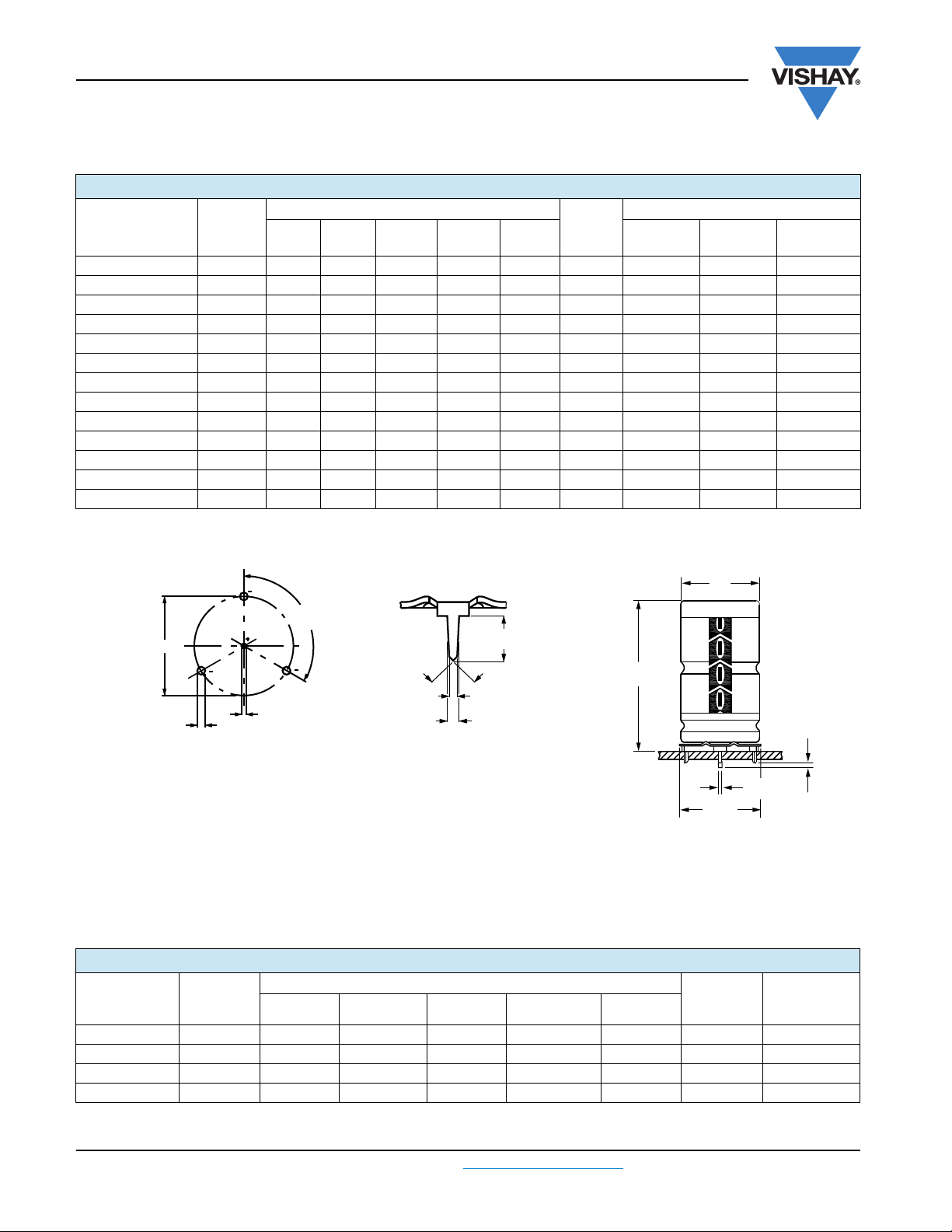
Mounting holes
Form MR:
Case Ø D x L = 15 mm x 30 mm to 21 mm x 38 mm
Especially for applications with severe shocks and vibrations
Fig.5 Mounting hole diagramm and outline. Form MR: with mounting ring and pins
Ø d1
D
L
Ø D2
1
+ 1.0
- 0.5
Vishay BCcomponents
Aluminum Capacitors
Axial Standard Miniature
Tab l e 1
AXIAL; DIMENSIONS in millimeters, MASS AND PACKAGING QUANTITIES
NOMINAL
CASE SIZE
Ø D x L
CASE
CODE
AXIAL: FORM AA, BA, and BR
ØdI
ØD
max.
L
max.
MASS
F
min.
(g)
4.5 x 10 2 0.6 - 5.0 10.5 15 0.5 - 1000 3000
6 x 10 3 0.6 - 6.3 10.5 15 0.7 - 1000 1000
8 x 11 5a 0.6 - 8.5 11.5 15 1.1 - 500 500
6.5 x 18 4 0.8 - 6.9 18.5 25 1.3 - 1000 1000
8 x 18 5 0.8 - 8.5 18.5 25 1.7 - 500 500
10 x 18 6 0.8 - 10.5 18.5 25 2.5 - 500 500
10 x 25 7 0.8 - 10.5 25.5 30 3.3 - 500 500
10 x 30 00 0.8 55 ± 1 10.5 30.5 35 4.8 340 - 500
12.5 x 30 01 0.8 55 ± 1 13.0 30.5 35 7.4 260 - 400
15 x 30 02 0.8 55 ± 1 15.5 30.5 35 11.7 200 - 250
18 x 30 03 0.8 55 ± 1 18.5 30.5 35 12.9 120 - -
18 x 38 04 0.8 34 ± 1 18.5 39.5 44 19.0 125 - -
21 x 38 05 0.8 34 ± 1 21.5 39.5 44 24.0 100 - -
Note
Detailed tape dimensions see section ‘PACKAGING’.
PACKAGING QUANTITIES
FORM
AA
FORM
BA
FORM
BR
Tab l e 2
MOUNTING RING; DIMENSIONS in millimeters, MASS AND PACKAGING QUANTITIES
NOMINAL
CASE SIZE
Ø D x L
CASE
CODE
15 x 30 02 0.8 1.0 + 0.4 17.5 16.5 ± 0.2 33 11.7 200
18 x 30 03 0.8 1.0 + 0.4 19.5 18.5 ± 0.2 33 12.9 240
18 x 38 04 0.8 1.0 + 0.4 19.5 18.5 ± 0.2 42 19.0 100
21 x 38 05 0.8 1.0 + 0.4 22.5 21.5 ± 0.2 42 24.0 100
www.vishay.com For technical questions, contact: aluminumcaps1@vishay.com
174 Revision: 06-Sep-10
Ø d1 Ød2
MOUNTING RING: FORM MR
ØD2
max.
D3
L
max.
MASS
(g)
PACKAGING
QUANTITIES
Document Number: 28325
Page 4

021 ASM
Aluminum Capacitors
Vishay BCcomponents
Axial Standard Miniature
ELECTRICAL DATA
SYMBOL DESCRIPTION
C
R
I
R
I
L5
tan max. dissipation factor at 100 Hz
ESR
Z max. impedance at 10 kHz
Note
Unless otherwise specified, all electrical values in table 3 apply at
T
=20C, P = 86 kPa to 106 kPa, RH = 45 % to 75 %.
amb
Tab l e 3
rated capacitance at 100 Hz, tolerance ± 20 %
rated RMS ripple current at 100 Hz, 85 C
max. leakage current after 5 min at U
equivalent series resistance at 100 Hz
(calculated from tan
max.
and CR)
R
ELECTRICAL DATA AND ORDERING INFORMATION
U
(V)
6.3
10
16
25
Document Number: 28325 For technical questions, contact: aluminumcaps1@vishay.com
Revision: 06-Sep-10 175
C
R
100 Hz
(µF)
1000 8 x 18 440 17 0.25 0.400 0.500 - 23102E3 33102E3 2200 10 x 25 710 32 0.29 0.210 0.160 - 90588E3 90589E3 -
1000 10 x 18 550 24 0.20 0.320 0.200 - 24102E3 34102E3 1500 10 x 25 690 34 0.23 0.250 0.180 - 90524E3 90525E3 1500 10 x 30 740 34 0.23 0.245 0.180 14152E3 24152E3 - 2200 12.5 x 30 980 48 0.25 0.177 0.095 14222E3 24222E3 - 3300 12.5 x 30 1090 70 0.27 0.128 0.095 14332E3 24332E3 - 4700 15 x 30 1320 98 0.29 0.100 0.070 14472E3 24472E3 - 44472E3
6800 18 x 30 1590 140 0.34 0.079 0.065 14682E3 - - 44682E3
10 000 18 x 38 2090 204 0.40 0.064 0.040 14103E3 - - 44103E3
15 000 21 x 38 2250 304 0.50 0.054 0.035 14153E3 - - 44153E3
1000 10 x 25 660 36 0.16 0.260 0.180 - 90517E3 90518E3 -
1000 10 x 30 700 36 0.16 0.260 0.175 15102E3 25102E3 - -
1500 12.5 x 30 950 52 0.19 0.205 0.095 15152E3 25152E3 - -
2200 12.5 x 30 1040 74 0.21 0.150 0.095 15222E3 25222E3 - -
3300 15 x 30 1290 110 0.23 0.111
4700 18 x 30 1560 154 0.25 0.087 0.065 15472E3 - - 45472E3
6800 18 x 38 2040 222 0.30 0.070 0.040 15682E3 - - 45682E3
10 000 21 x 38 2170 324 0.36 0.058 0.035 15103E3 - - 45103E3
1000 12.5 x 30 840 54 0.14 0.220 0.095 16102E3 26102E3 - -
1500 12.5 x 30 950 79 0.17 0.179 0.095 16152E3 26152E3 - -
NOMINAL
R
CASE SIZE
ØD x L
(mm)
470 8 x 11 260 10 0.25 0.850 0.640 - 23471E3 33471E3 -
100 4.5 x 10 100 6 0.20 3.200 2.000 - 24101E3 34101E3 220 6 x 10 160 8.4 0.20 1.500 0.910 - 24221E3 34221E3 330 8 x 11 230 11 0.20
470 6.5 x 18 310 13 0.20 0.680 0.430 - 24471E3 34471E3 680 8 x 18 400 18 0.20 0.470 0.290 - 24681E3 34681E3 -
68 4.5 x 10 90 6.2 0.16 3.800 2.400 - 25689E3 35689E3 150 6 x 10 140 8.8 0.16 1.700 1.100 - 25151E3 35151E3 220 8 x 11 210 11 0.16 1.200 0.730 - 25221E3 35221E3 330 6.5 x 18 290 15 0.16 0.770 0.480 - 25331E3 35331E3 470 8 x 18 380 19 0.16 0.550 0.340 - 25471E3 35471E3 680 10 x 18 500 26 0.16 0.380 0.240 - 25681E3 35681E3 -
47 4.5 x 10 80 6.4 0.14 4.800 2.600 - 26479E3 36479E3 100 6 x 10 150 9 0.14 2.300 1.200 - 26101E3 36101E3 150 8 x 11 190 12 0.14 1.500 0.800 - 90534E3 90535E3 150 6.5 x 18 210 12 0.14 1.500 0.800 - 26151E3 36151E3 220 6.5 x 18 250 15 0.14 1.000 0.550 - 26221E3 36221E3 330 8 x 18 340 21 0.14 0.680 0.360 - 26331E3 36331E3 470 10 x 18 450 28 0.14 0.480 0.260 - 26471E3 36471E3E 680 10 x 25 560 38 0.14 0.330 0.180 - 90527E3 90528E3 680 10 x 30 640 38 0.14 0.323 0.175 16681E3 26681E3 - -
I
R
100 Hz
85 C
(mA)
I
L5
5min
(µA)
tan
100Hz
ORDERING EXAMPLE
Electrolytic capacitor 021 series
1000 µF/16 V; ±20 %
Nominal case size: Ø 10 mm x 25 mm; Form BA
Ordering code: MAL202190518E3
Former 12 NC: 2222 021 90518
ORDERING CODE MAL2021.......
ESR
100 Hz
()
1.000
Z
10 kHz
()
0.610 - 24331E3 34331E3 -
0.070
IN BOX
FORM
AA
15332E3 25332E3 - 45332E3
TAPED
ON REEL
FORM
BR
TAPED
IN BOX
FORM
BA
MOUNTING
RING
FORM
MR
www.vishay.com
Page 5

021 ASM
Vishay BCcomponents
Aluminum Capacitors
Axial Standard Miniature
ELECTRICAL DATA AND ORDERING INFORMATION
U
(V)
25
40
63
100
www.vishay.com For technical questions, contact: aluminumcaps1@vishay.com
176 Revision: 06-Sep-10
C
R
100 Hz
(µF)
2200 15 x 30 1180 114 0.19 0.132 0.070 16222E3 26222E3 - 46222E3
3300 18 x 30 1470 169 0.21 0.099 0.065 16332E3 - - 46332E3
4700 18 x 38 1920 239 0.23 0.079 0.040 16472E3 - - 46472E3
6800 21 x 38 2070 344 0.28 0.064 0.035 16682E3 - - 46682E3
1000 12.5 x 30 900 84 0.12 0.190 0.110 17102E3 27102E3 - 1500 15 x 30 1120 124 0.15 0.159 0.070 17152E3 27152E3 - 47152E3
2200 18 x 30 1390 180 0.17 0.118 0.065 17222E3 - - 47222E3
3300 18 x 38 1810 268 0.19 0.090 0.040 17332E3 - - 47332E3
4700 21 x 38 1940 380 0.21 0.072 0.035 17472E3 - - 47472E3
0.47 4.5 x 10 8 4.1 0.09 310.0 120.0 - 28477E3 38477E3 -
1000 18 x 30 1170 130 0.08 0.135 0.075 18102E3 - - 48102E3
1500 18 x 38 1530 193 0.11 0.122 0.045 18152E3 - - 48152E3
2200 21 x 38 1780 281 0.13 0.099 0.040 18222E3 - - 48222E3
1000 21 x 38 1470 204 0.10 0.160 0.150 19102E3 - - 49102E3
NOMINAL
R
CASE SIZE
ØD x L
(mm)
22 4.5 x 10 60 5.8 0.11 8.000 3.200 - 27229E3 37229E3 -
47 6 x 10 110 7.8 0.11 3.800
100 8 x 11 170 12 0.11 1.800 0.700 - 90537E3 90538E3 100 6.5 x 18 190 12 0.11 1.800 0.700 - 27101E3 37101E3 150 8 x 18 250 16 0.11 1.100 0.470 - 27151E3 37151E3 220 10 x 18 330 22 0.11 0.800 0.320 - 27221E3 37221E3 330 10 x 25 430 30 0.11 0.530 0.210 - 27331E3 37331E3 470 10 x 25 520 42 0.11 0.370 0.180 - 90514E3 90515E3 470 10 x 30 590 42 0.12 0.404 0.175 17471E3 27471E3 - 680 12.5 x 30 800 58 0.12 0.297 0.110 17681E3 27681E3 - -
1 4.5 x 10 12 4.1 0.09 150.0 55.00 - 28108E3 38108E3 -
2.2 4.5 x 10 21 4.3 0.09
3.3 4.5 x 10 25 4.4 0.09 44.00 17.00 - 28338E3 38338E3 -
4.7 4.5 x 10 31 4.6 0.09 31.00 12.00 - 28478E3 38478E3 10 4.5 x 10 50 5.3 0.08 13.00 5.500 - 28109E3 38109E3 15 4.5 x 10 55 5.9 0.08 8.500 3.700 - 28159E3 38159E3 22 6 x 10 90 6.8 0.08 5.800 2.500 - 28229E3 38229E3 33 6 x 10 100 8.2 0.08 3.900 1.700 - 28339E3 38339E3 47 8 x 11 140 10 0.08
47 6.5 x 18 150 10 0.08 2.700 1.200 - 28479E3 38479E3 68 8 x 11 160 13 0.08 1.900 0.810 - 90544E3 90545E3 68 6.5 x 18 170 13 0.08 1.900 0.810 - 28689E3 38689E3 -
100 8 x 18 250 17 0.08 1.300 0.550 - 28101E3 38101E3 150 10 x 18 320 23 0.08 0.850 0.370 - 28151E3 38151E3 220 10 x 25 430 32 0.08 0.600 0.250 - 90511E3 90512E3 220 10 x 30 480 32 0.08 0.614 0.260 18221E3 28221E3 - 330 12.5 x 30 610 46 0.08 0.409 0.190 18331E3 28331E3 - 470 12.5 x 30 700 63 0.08 0.287 0.130 18471E3 28471E3 - 680 15 x 30 890 90 0.08 0.199 0.095 18681E3 28681E3 - 48681E3
1 4.5 x 10 14 4.2 0.08 130.0 90.00 - 29108E3 39108E3 -
2.2 4.5 x 10 20 4.4 0.08 58.00 41.00 - 29228E3 39228E3 -
4.7 4.5 x 10 30 4.9 0.08 27.00 19.00 - 29478E3 39478E3 10 6 x 10 65 6 0.08 13.00 9.000 - 29109E3 39109E3 15 8 x 11 77 7 0.08 8.500 6.000 - 90547E3 90548E3 15 6.5 x 18 85 7 0.08 8.500 6.000 - 29159E3 39159E3 22 8 x 11 95 8.4 0.08 5.800 4.100 - 90551E3 90552E3 22 6.5 x 18 100 8.4 0.08 5.800 4.100 - 29229E3 39229E3 33 6.5 x 18 120 10.6 0.08 3.900 2.700 - 29339E3 39339E3 47 8 x 18 160 13.4 0.08 2.700 1.900 - 29479E3 39479E3 68 10 x 18 220 17.6 0.08 1.900 1.300 - 29689E3 39689E3 -
100 10 x 25 300 24 0.08 1.300 0.900 - 90531E3 90532E3 100 10 x 30 340 24 0.07 1.150 1.000 19101E3 29101E3 - 150 12.5 x 30 490 34 0.07 0.645 0.610 19151E3 29151E3 - 220 12.5 x 30 560 48 0.08 0.610 0.560 19221E3 29221E3 - 330 15 x 30 740 70 0.09 0.420 0.400 19331E3 29331E3 - 49331E3
470 18 x 30 980 98 0.09 0.310 0.290 19471E3 - - 49471E3
680 18 x 38 1260 140 0.09 0.195 0.180 19681E3 - - 49681E3
I
R
100 Hz
85 C
(mA)
I
L5
5min
(µA)
tan
100Hz
ESR
100 Hz
()
65.00
2.700
Z
10 kHz
()
1.500
25.00 - 28228E3 38228E3 -
1.200 - 90541E3 90542E3 -
ORDERING CODE MAL2021.......
IN BOX
FORM
AA
- 27479E3 37479E3 -
TAPED
ON REEL
FORM
BR
TAPED
IN BOX
FORM
BA
Document Number: 28325
MOUNTING
RING
FORM
MR
Page 6

021 ASM
3.3
3.2
3.0
2.8
2.6
2.4
2.2
2.0
1.8
1.6
1.4
1.2
1.0
0.8
0.5
0.0
3.1
40 50 60 70 80 90 100
CCC205
lifetime multiplier
(1)
70
50
4.0
6.0
2.0
1.5
30
15
10
3.0
20
1.0
I
A
I
R
IA = Actual ripple current at 100 Hz
I
R
= Rated ripple current at 100 Hz, 85 °C
(1)
Useful life at 85 °C and IR applied:
Case Ø D x L = 4.5 mm x 10 mm to 10 mm x 25 mm: 2500 h
Case Ø D x L = 10 mm x 30 mm to 21 mm x 38 mm: 8000 h
Fig.6 Multiplier of useful life as a function of ambient temperature and ripple current load
T
amb
(°C)
Aluminum Capacitors
Axial Standard Miniature
ADDITIONAL ELECTRICAL DATA
PARAMETER CONDITIONS
Volt ag e
Surge voltage U
Reverse voltage U
Current
Leakage current After 1 min at U
After 5 min at U
Inductance
Equivalent series inductance (ESL) CaseØ D x L mm:
R
R
4.5 x 10 typ. 10 nH 6 x 10 typ. 22 nH 8 x 11 typ. 85 nH -
6.5 x 18 typ. 25 nH 8 x 18 typ. 40 nH -
10 x 18 typ. 61 nH 10 x 25 typ. 38 nH 10 x 30 typ. 38 nH -
12.5 x 30 typ. 46 nH 15 x 30 typ. 48 nH typ. 39 nH
18 x 30 typ. 50 nH typ. 39 nH
18 x 38 typ. 54 nH typ. 39 nH
21 x 38 typ. 59 nH typ. 39 nH
Vishay BCcomponents
AXIAL MOUNTING RING
1.15 x U
s
1V
rev
IL1 0.006 CRxUR+4µA
IL5 0.002 CRxUR+4µA
R
VALUE
RIPPLE CURRENT AND USEFUL LIFE
Document Number: 28325 For technical questions, contact: aluminumcaps1@vishay.com
Revision: 06-Sep-10 177
www.vishay.com
Page 7

021 ASM
Vishay BCcomponents
Aluminum Capacitors
Axial Standard Miniature
Tab l e 4
MULTIPLIER OF RIPPLE CURRENT (IR) AS A FUNCTION OF FREQUENCY
I
MULTIPLIER
FREQUENCY
(Hz)
U
= 6.3 V to 16 V UR=25V to40V UR= 63 V to 100 V
R
50 0.95 0.90 0.85
100 1.00 1.00 1.00
300 1.07 1.12 1.20
1000 1.12 1.20 1.30
3000 1.15 1.25 1.35
10 000 1.20 1.30 1.40
Tab l e 5
TEST PROCEDURES AND REQUIREMENTS
TEST
NAME OF TEST REFERENCE
Endurance IEC 60384-4/
EN130300
subclause 4.13
Useful life CECC 30301
subclause 1.8.1
Shelf life
(storage at
high temperature)
IEC 60384-4/
EN130300
subclause 4.17
T
amb
case Ø D x L = 4.5 mm x 10 mm to
U
U
case Ø D x L = 10 mm x 30 m to
U
T
amb
case Ø D x L = 10 mm x 30 mm to
T
amb
case Ø D x L = 4.5 mm x 10 mm to
case Ø D x L = 10 mm x 30 mm to
T
amb
500 h
after test: U
24 h to 48 h before measurement
PROCEDURE
(quick reference)
=85°C; UR applied;
= 6.3 V to 25 V: 1000 h;
R
= 40 V to 100 V: 2000 h;
R
= 6.3 to 100 V: 5000 h
R
= 105 °C; UR applied;
=85°C; UR and IR applied;
=85C; no voltage applied;
to be applied for 30 min,
R
R
10 mm x 25 mm:
21 mm x 38 mm:
21 mm x 38 mm: 2000 h
10 mm x 25 mm: 2500 h;
21 mm x 38 mm: 8000 h
6.3 V; C/C: + 15 %/- 30 %
U
R
6.3 V; C/C: ± 15 %
U
R
tan 1.3 x spec. limit
Z 2 x spec. limit
spec. limit
I
L5
C/C: ± 20 %
tan 1.6 x spec. limit
Z 2 x spec. limit
I
spec. limit
L5
U
6.3 V; C/C: + 45 %/- 50 %
R
6.3 V; C/C: ± 45 %
U
R
tan 3 x spec. limit
Z 3 x spec. limit
spec. limit
I
L5
no short or open circuit
total failure percentage: 1 %
C/C, tan ,Z:
for requirements
see ‘Endurance test’ above
I
2 x spec. limit
L5
REQUIREMENTS
www.vishay.com For technical questions, contact: aluminumcaps1@vishay.com
Document Number: 28325
178 Revision: 06-Sep-10
Page 8

Legal Disclaimer Notice
Vishay
Disclaimer
All product specifications and data are subject to change without notice.
Vishay Intertechnology, Inc., its affiliates, agents, and employees, and all persons acting on its or their behalf
(collectively, “Vishay”), disclaim any and all liability for any errors, inaccuracies or incompleteness contained herein
or in any other disclosure relating to any product.
Vishay disclaims any and all liability arising out of the use or application of any product described herein or of any
information provided herein to the maximum extent permitted by law. The product specifications do not expand or
otherwise modify Vishay’s terms and conditions of purchase, including but not limited to the warranty expressed
therein, which apply to these products.
No license, express or implied, by estoppel or otherwise, to any intellectual property rights is granted by this
document or by any conduct of Vishay.
The products shown herein are not designed for use in medical, life-saving, or life-sustaining applications unless
otherwise expressly indicated. Customers using or selling Vishay products not expressly indicated for use in such
applications do so entirely at their own risk and agree to fully indemnify Vishay for any damages arising or resulting
from such use or sale. Please contact authorized Vishay personnel to obtain written terms and conditions regarding
products designed for such applications.
Product names and markings noted herein may be trademarks of their respective owners.
Document Number: 91000 www.vishay.com
Revision: 18-Jul-08 1
 Loading...