

Page 1

MBA/SMA 0204, MBB/SMA 0207, MBE/SMA 0414 - Professional
Vishay Beyschlag
Professional Leaded Resistors
FEATURES
• Approved according to CECC 40101-806
• Advanced thin film technology
• Power dissipation rating up to 1 W
• Excellent overall stability: class 0.25
• Wide professional range: 0.22 Ω to 22 MΩ
• Lead (Pb)-free solder contacts
• Pure tin plating provides compatibility with lead (Pb)-free
and lead containing soldering processes
• Compatible with “Restriction of the use of Hazardous
Substances” (RoHS) directive 2002/95/EC (issue 2004)
DESCRIPTION
MBA/SMA 0204, MBB/SMA 0207 and MBE/SMA 0414
professional leaded thin film resistors are the general
purpose resistor for all fields of professional electronics
where reliability and stability is of major concern. Typical
applications include industrial, telecommunication and
medical equipment.
APPLICATIONS
• Industrial
• Telecommunication
• Medical equipment
METRIC SIZE
DIN: 0204 0207 0414
CECC: A B D
TECHNICAL SPECIFICATIONS
DESCRIPTION MBA/SMA 0204 MBB/SMA 0207 MBE/SMA 0414
CECC size A B D
Resistance range 0.22 Ω to 10 MΩ 0.22 Ω to 22 MΩ 0.22 Ω to 22 MΩ
Resistance tolerance ± 5 %; ± 1 %; ± 0.5 %
Temperature coefficient ± 50 ppm/K; ± 25 ppm/K
Operation mode long term standard long term standard long term standard
Climatic category (LCT/UCT/days) 55/125/56 55/155/56 55/125/56 55/155/56 55/125/56 55/155/56
Rated dissipation, P
Operating voltage, U
Film temperature 125 °C 155 °C 125 °C 155 °C 125 °C155°C
Max. resistance change at P
for resistance range, ΔR/R max., after:
70
AC/DC 200 V 350 V 500 V
max
70
1000 h ≤ 0.25 % ≤ 0.5 % ≤ 0.25 % ≤ 0.5 % ≤ 0.2 % ≤ 0.4 %
0.25 W 0.4 W 0.4 W 0.6 W 0.65 W 1.0 W
1 Ω to 332 kΩ 1 Ω to 1 MΩ 1 Ω to 2.4 MΩ
8000 h ≤ 0.5 % ≤ 1.0 % ≤ 0.5 % ≤ 1.0 % ≤ 0.4 % ≤ 0.8 %
225 000 h ≤ 1.5 % - ≤ 1.5 % - ≤ 1.2 % -
Specified lifetime 225 000 h 8000 h 225 000 h 8000 h 225 000 h 8000 h
Permissible voltage against ambient:
1 minute 300 V 500 V 800 V
continuous 75 V 75 V 75 V
Failure rate ≤ 0.7 x 10
Note:
MB_ series has been merged with the related SMA series to form one series “MB_/SMA__”.
www.vishay.com For technical questions, contact: ff3cresistors@vishay.com Document Number: 28766
22 Revision: 28-Aug-07
-9
/h ≤ 0.3 x 10⁻⁹/h ≤ 0.1 x 10⁻⁹/h
Page 2

MBA/SMA 0204, MBB/SMA 0207, MBE/SMA 0414 - Professional
Professional Leaded Resistors
PART NUMBER AND PRODUCT DESCRIPTION
PART NUMBER: MBB02070C1001FCT00
B2 0C10FCT0BM 701000
MODEL/SIZE SPECIAL CHARACTER TCR/MATERIAL VALUE TOLERANCE
2
3
4
5
6
PA CK A GI N G
D = ± 0.5 %
F = ± 1 %
J = ± 5 %
Z = Jumper
CT
C1
RP
R1
R2
R4
N4
(1)
MBA0204
MBA/SMA 0204
MBB0207
MBB/SMA 0207
MBE0414
MBE/SMA 0414
PRODUCT DESCRIPTION: MBB/SMA 0207-50 1 % CT 1K0
Notes:
(1)
Please refer to table PACKAGING for complete information.
The PART NUMBER shown above is to facilitate the unified part numbering system for ordering products.
=
=
=
MBB/SMA 0207 - 50 1 % CT 1K0
MODEL/SIZE TCR TOLERANCE
MBA/SMA 0204
MBB/SMA 0207
MBE/SMA 0414
0 = neutral
N = RB Radial 5 mm
S = UB Radial 2.5 mm
D = ± 25 ppm/K
C = ± 50 ppm/K
Z = Jumper
± 25 ppm/K
± 50 ppm/K
3 digit value
1 digit multiplier
MULTIPLIER
-3
7 = *10
8 = *10
9 = *10
0 = *100 5 = *10
1 = *101 6 = *10
2 = *10
-2
3 = *10
-1
4 = *10
0000 = Jumper
± 0.5 %
± 1.0 %
± 5.0 %
Vishay Beyschlag
PA CK A GI N G
(1)
CT
C1
RP
R1
R2
R4
N4
RESISTANCE
1K0 = 1 kΩ
51R1 = 51.1 Ω
SPECIAL
00 = standard
PACKAGING
MODEL
MBA/SMA 0204
MBB/SMA 0207
MBE/SMA 0414 2500 R2 1000 C1
PIECES CODE PIECES CODE
1000
5000
1000
4000
5000
REEL BOX
R1
RP
R1
R4 (for RB, UB)
RP
1000
5000
1000
4000
5000
C1
CT
C1
N4 (for RB, UB)
CT
12NC CODE FOR HISTORICAL CODING REFERENCE OF MBA 0204/MBB 0207/MBE 0414
DESCRIPTION
TYPE TCR TOL. C1 1000 units CT 5000 units R1 1000 units R2 2500 units RP 5000 units
± 50 ppm/K
MBA 0204
± 25 ppm/K
jumper - 900 90001 905 90001 700 90001 - 805 90001
± 50 ppm/K
MBB 0207
± 25 ppm/K
jumper - 910 90001 915 90001 710 90001 - 815 90001
± 50 ppm/K
MBE 0414
± 25 ppm/K
Document Number: 28766 For technical questions, contact: ff3cresistors@vishay.com
Revision: 28-Aug-07 23
± 5 % 900 3.... 905 3.... 700 3.... - 805 3....
± 1 % 900 1.... 905 1.... 700 1.... - 805 1....
± 0.5 % 900 5.... 905 5.... 700 5.... - 805 5....
± 1 % 901 1.... 906 1.... 701 1.... - 806 1....
± 0.5 % 901 5.... 906 5.... 701 5.... - 806 5....
± 5 % 910 3.... 915 3.... 710 3.... - 815 3....
± 1 % 910 1.... 915 1.... 710 1.... - 815 1....
± 0.5 % 910 5.... 915 5.... 710 5.... - 815 5....
± 1 % 911 1.... 916 1.... 711 1.... - 816 1....
± 0.5 % 911 5.... 916 5.... 711 5.... - 816 5....
± 5 % 920 3.... - - 825 3.... -
± 1 % 920 1.... - - 825 1.... -
± 0.5 % 920 5.... - - 825 5.... -
± 1 % 921 1.... - - 826 1.... -
± 0.5 % 921 5.... - - 826 5.... -
AMMOPACK REEL
ORDERING CODE 2312 ... .....
www.vishay.com
Page 3

MBA/SMA 0204, MBB/SMA 0207, MBE/SMA 0414 - Professional
Vishay Beyschlag
Professional Leaded Resistors
12NC INFORMATION
Last Digit of 12NC Indicating Resistance Decade
RESISTANCE DECADE LAST DIGIT
0.1 Ω to 0.999 Ω 7
1 Ω to 9.99 Ω 8
10 Ω to 99.9 Ω 9
100 Ω to 999 Ω 1
1 kΩ to 9.99 kΩ 2
10 kΩ to 99.9 kΩ 3
100 kΩ to 999 kΩ 4
1MΩ to 9.99 MΩ 5
10 MΩ to 99.9 MΩ 6
12NC Example (for Historical Coding reference of
MBA 0204/MBB 0207/MBE 0414)
The 12NC code of a MBA 0204 resistor, value 47.5 kΩ and
TCR 50 with ± 1 % tolerance, supplied on bandolier in a box
of 5000 units is: 2312 905 14753.
DIMENSIONS
L
I
I
D
M
d
DIMENSIONS - leaded resistor types, mass and relevant physical dimensions
TYPE
D
max
(mm)
L
max
(mm)
MBA/SMA 0204 1.6 3.6 0.5 29.0 5.0 125
MBB/SMA 0207 2.5 6.3 0.6 28.0 10.0
MBE/SMA 0414 4.0 11.9 0.8 31.0 15.0 700
Note:
(1)
For 7.5 ≤ M < 10.0 mm, use version MBB/SMA 0207 ... L0 without lacquer on the leads.
d
nom
(mm)
I
min
(mm)
M
min
(mm)
(1)
MASS
(mg)
220
TEMPERATURE COEFFICIENT AND RESISTANCE RANGE
DESCRIPTION
RESISTANCE VALUE
TCR TOLERANCE MBA/SMA 0204 MBB/SMA 0207 MBE/SMA 0414
0.22 Ω to 0.91 Ω
± 50 ppm/K
± 5 % 0.22 Ω to 0.91 Ω 0.22 Ω to 0.91 Ω
± 1 % 1 Ω to 10 MΩ 1 Ω to 10 MΩ 1 Ω to 22 MΩ
11 MΩ to 22 MΩ
± 0.5 % 10 Ω to 475 kΩ 10 Ω to 1 MΩ 10 Ω to 2.4 MΩ
± 1 % 10 Ω to 475 kΩ 10 Ω to 1 MΩ 10 Ω to 2.4 MΩ
± 25 ppm/K
± 0.5 % 10 Ω to 475 kΩ 10 Ω to 1 MΩ 10 Ω to 2.4 MΩ
Jumper - ≤ 10 mΩ; I
= 3.0 A ≤ 10 mΩ, I
max
max
Note:
(2)
Resistance value to be selected from E24 series for ± 5 % tolerance, from E24/E96 series for ± 1 % tolerance and from E24/E192 for ± 0.5 %
tolerance.
Resistance ranges printed in bold are preferred TCR/tolerance combinations with optimized availablility.
(2)
= 5.0 A -
www.vishay.com For technical questions, contact: ff3cresistors@vishay.com Document Number: 28766
24 Revision: 28-Aug-07
Page 4

MBA/SMA 0204, MBB/SMA 0207, MBE/SMA 0414 - Professional
Professional Leaded Resistors
DESCRIPTION
Production is strictly controlled and follows an extensive
set of instructions established for reproducibility. A
homogeneous film of metal alloy is deposited on a high grade
ceramic body (85 % Al
desired temperature coefficient. Nickel plated steel
termination caps are firmly pressed on the metallised rods. A
special laser is used to achieve the target value by smoothly
cutting a helical groove in the resistive layer without
damaging the ceramics. Connecting wires of electrolytic
copper plated with 100 % pure tin are welded to the
termination caps. The resistor elements are covered by a
light blue protective coating designed for electrical,
mechanical and climatic protection. Four or five colour code
rings designate the resistance value and tolerance in
accordance with IEC 60062.
The result of the determined production is verified by an
extensive testing procedure performed on 100 % of the
individual resistors. Only accepted products are stuck
directly on the adhesive tapes in accordance with
IEC 60286-1.
) and conditioned to achieve the
2O3
Vishay Beyschlag
APPROVALS
The resistors are tested in accordance with CECC
40101-806 which refers to EN 60 115-1 and EN 140 100.
Approval of conformity is indicated by the CECC logo on the
package label.
Vishay BEYSCHLAG has achieved "Approval of
Manufacturer" in accordance with EN 100114-1.
SPECIALS
This product family of leaded thin film resistors for
professional applications is complemented by Zero Ohm
Jumpers and isolators.
On request, resistors are available with established reliability
in accordance with CECC 40 101-806 Version E. Please
refer to the special data sheet for information on failure rate
level, available resistance ranges and ordering codes.
ASSEMBLY
The resistors are suitable for processing on automatic
insertion equipment and cutting and bending machines.
Excellent solderability is proven, even after extended
storage. They are suitable for automatic soldering using
wave or dipping. The encapsulation is resistant to all
cleaning solvents commonly used in the electronics industry,
including alcohols, esters and aqueous solutions. The
suitability of conformal coatings, if applied, shall be qualified
by appropriate means to ensure the long-term stability of the
whole system. The resistors are completely lead (Pb)-free,
the pure tin plating provides compatibility with lead (Pb)-free
and lead-containing soldering processes. The immunity of
the plating against tin whisker growth has been proven under
extensive testing. All products comply with the
CEFIC-EECA-EICTA list of legal restrictions on hazardous
substances. This includes full compliance with the following
directives:
• 2000/53/EC End of Vehicle Life Directive (ELV)
2000/53/EC Annex II to End of Vehicle Life Directive (ELV II)
•
• 2002/95/EC Restriction of the use of Hazardous
Substances Directive (RoHS)
• 2002/96/EC Waste Electrical and Electrical Equipment
Directive (WEEE)
Document Number: 28766 For technical questions, contact: ff3cresistors@vishay.com
Revision: 28-Aug-07 25
www.vishay.com
Page 5
MBA/SMA 0204, MBB/SMA 0207, MBE/SMA 0414 - Professional
Vishay Beyschlag
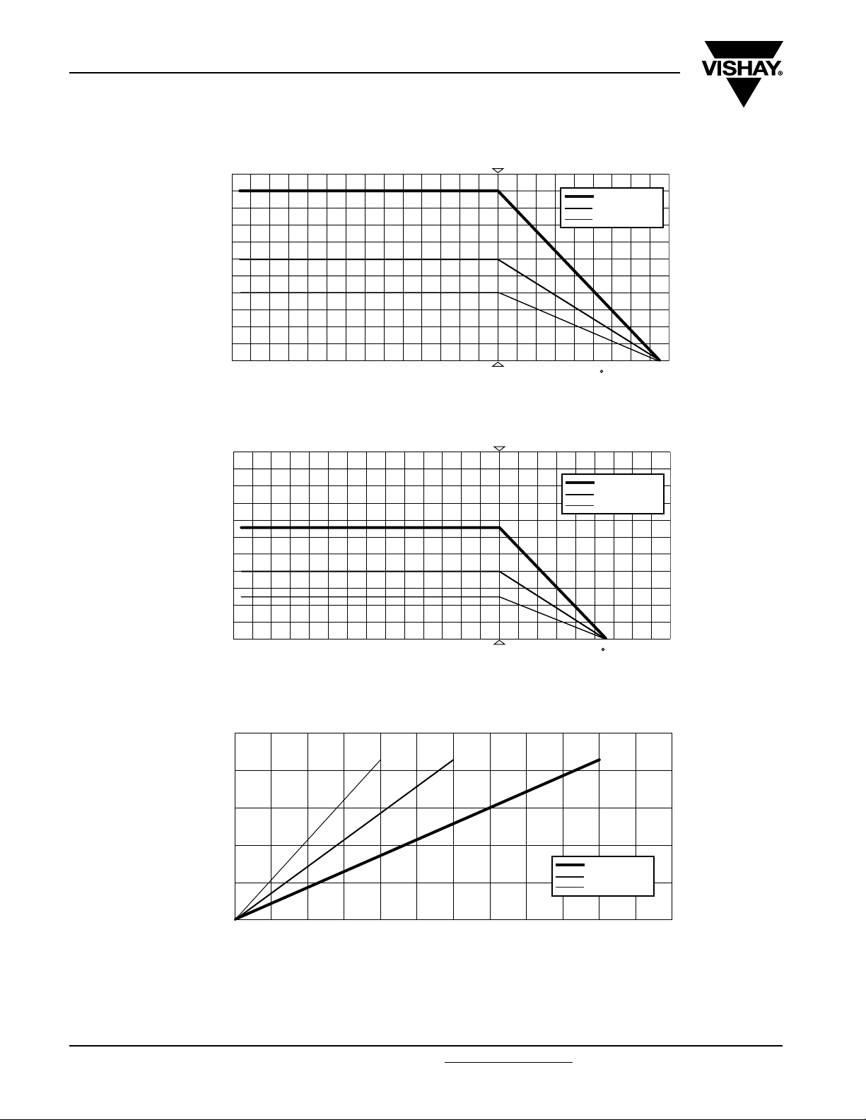
FUNCTIONAL PERFORMANCE
P
1
W
0.5
Power Dissipation
0
- 50 50
Derating - Standard Operation
P
1
W
Professional Leaded Resistors
0
70
Ambient Temperature
MBE/SMA 0414
MBB/SMA 0207
MBA/SMA 0204
100 150
C
ϑ
MBE/SMA 0414
MBB/SMA 0207
MBA/SMA 0204
amb
0.5
Power Dissipation
0
- 50 50
Derating Long Term Operation
r
T
80
K
60
Temperature Rise
40
20
0
0 0.4 0.8 1 1.20.2 0.60.1 0.3 0.5 0.7 0.9 1.1 W
Temperature Rise
0
Rise of surface temperature
70
100 150
Ambient Temperature
C
MBE/SMA 0414
MBB/SMA 0207
MBA/SMA 0204
Load
ϑ
amb
P
www.vishay.com For technical questions, contact: ff3cresistors@vishay.com Document Number: 28766
26 Revision: 28-Aug-07
Page 6

MBA/SMA 0204, MBB/SMA 0207, MBE/SMA 0414 - Professional
Professional Leaded Resistors
max
P
100
W
10
Pulse Load
1
0.1
10 µs 100 ms
Maximum pulse load, single pulse; for permissible resistance change equivalent to 8000 h operation.
100 µs 1 ms 10 ms
Single Pulse
max
P
100
W
MBE/SMA 0414
MBB/SMA 0207
MBA/SMA 0204
1 s
Pulse Duration
MBE/SMA 0414
MBB/SMA 0207
MBA/SMA 0204
Vishay Beyschlag
10 s
t
i
10
1
Continuous Pulse Load
0.1
10 µs 100 ms
Maximum pulse load, continuous pulses; for permissible resistance change equivalent to 8000 h operation.
100 µs 1 ms 10 ms
1 s
Pulse Duration
10 s
t
i
Continuous Pulse
max
U
Pulse Voltage
100 V
1 kV
100 µs 1 ms 10 ms
MBE/SMA 0414
MBB/SMA 0207
MBA/SMA 0204
1 s
Pulse Duration
10 s10 µs 100 ms
t
i
Maximum pulse voltage, single and continuous pulses; for permissible resistance change equivalent to 8000 h operation.
Pulse Voltage
Document Number: 28766 For technical questions, contact: ff3cresistors@vishay.com
Revision: 28-Aug-07 27
www.vishay.com
Page 7

MBA/SMA 0204, MBB/SMA 0207, MBE/SMA 0414 - Professional
Vishay Beyschlag
10 kV
Test Voltage
1 kV
100 V
10 V
Pulse load rating in accordance with IEC 60115-1, 4.27; 1.2 µs/50 µs; 5 pulses at 12 s intervals;
1.2/50 Pulse
10 kV
10 Ω
Professional Leaded Resistors
MBE/SMA 0414
MBB/SMA 0207
MBA/SMA 0204
100 Ω 1 kΩ 100 kΩ 1 MΩ
for permissible resistance change 0.5 %.
10 kΩ
Resistance Value
10 MΩ
R
Test Voltage
1 kV
100 V
10 V
10 Ω
Pulse load rating in accordance with IEC 60115-1, 4.27; 10 µs/700 µs; 10 pulses at 1 minute intervals;
10/700 Pulse
1
A
1
µV/V
Current Noise
0.1
0.01
1 kΩ
100 Ω 1 kΩ 100 kΩ 1 MΩ
for permissible resistance change 0.5 %.
10 kΩ
MBE/SMA 0414
MBB/SMA 0207
MBA/SMA 0204
Resistance Value
1 MΩ
Resistance Value
MBE/SMA 0414
MBB/SMA 0207
MBA/SMA 0204
10 MΩ10 kΩ 100 kΩ
10 MΩ
Current noise - A1 In Accordance With IEC 60195
R
R
www.vishay.com For technical questions, contact: ff3cresistors@vishay.com Document Number: 28766
28 Revision: 28-Aug-07
Page 8

MBA/SMA 0204, MBB/SMA 0207, MBE/SMA 0414 - Professional
Professional Leaded Resistors
TESTS AND REQUIREMENTS
Essentially all tests are carried out in accordance with the
following specifications:
EN 140000/IEC 60115-1, Generic specification (includes
tests)
EN 140100/IEC 60115-2, Sectional specification (includes
schedule for qualification approval)
CECC 40101-806, Detail specification (includes schedule for
conformance inspection)
Most of the components are approved in accordance with the
European CECC-system, where applicable. The Test and
Requirements table contains only the most important tests.
For the full test schedule refer to the documents listed above.
The testing also covers most of the requirements specified
by EIA/IS-703 and JIS-C-5202.
Vishay Beyschlag
Unless otherwise specified the following values apply:
Temperature: 15 °C to 35 °C
Relative humidity: 45 % to 75 %
Air pressure: 86 kPa to 106 kPa (860 mbar to 1060 mbar).
For testing the components are mounted on a test board in
accordance with IEC 60115-1, 4.31 unless otherwise
specified.
In Test and Requirements Table, only the tests and
requirements are listed with reference to the relevant clauses
of IEC 60115-1 and IEC 60068-2; a short description of the
test procedure is also given.
The tests are carried out in accordance with IEC 60068 and
under standard atmospheric conditions in accordance with
IEC 60068-1, 5.3. Climatic category LCT/UCT/56 (rated
temperature range: Lower Category Temperature, Upper
Category Temperature; damp heat, long term, 56 days) is
valid.
TEST PROCEDURES AND REQUIREMENTS
IEC
60115-1
CLAUSE
IEC
60068-2
TEST
METHOD
TEST PROCEDURE
stability for product
types:
MBA/SMA 0204 1 Ω to 332 kΩ 0.22 Ω to < 1 Ω > 332 kΩ
MBB/SMA 0207 1 Ω to 1 MΩ 0.22 Ω to < 1 Ω > 1 MΩ
STABILITY
CLASS 0.5
REQUIREMENTS
PERMISSIBLE CHANGE (ΔR
STABILITY
CLASS 1
max
)
STABILITY
CLASS 2
MBE/SMA 0414 1 Ω to 2.4 MΩ 0.22 Ω to < 1 Ω > 2.4 MΩ
4.5 - resistance ± 5 %; ± 1 %; ± 0.5 %
4.8.4.2 -
Document Number: 28766 For technical questions, contact: ff3cresistors@vishay.com
Revision: 28-Aug-07 29
temperature
coefficient
at 20/LCT/20 °C and
20/UCT/20 °C
± 50 ppm/K; ± 25 ppm/K
www.vishay.com
Page 9

MBA/SMA 0204, MBB/SMA 0207, MBE/SMA 0414 - Professional
Vishay Beyschlag
Professional Leaded Resistors
TEST PROCEDURES AND REQUIREMENTS
IEC
60115-1
CLAUSE
IEC
60068-2
TEST
METHOD
-
TEST PROCEDURE
stability for product
types:
MBA/SMA 0204 1 Ω to 332 kΩ 0.22 Ω to < 1 Ω > 332 kΩ
MBB/SMA 0207 1 Ω to 1 MΩ 0.22 Ω to < 1 Ω > 1 MΩ
MBE/SMA 0414 1 Ω to 2.4 MΩ 0.22 Ω to < 1 Ω > 2.4 MΩ
endurance at
70 °C: standard
operation mode
U = or
1.5 h on; 0.5 h off
P70 x R
U = U
max
REQUIREMENTS
PERMISSIBLE CHANGE (ΔR
STABILITY
CLASS 0.5
;
STABILITY
CLASS 1
max
)
STABILITY
CLASS 2
70 °C; 1000 h ± (0.5 % R + 0.05 Ω) ± (0.5 % R +0.05 Ω) ± 0.5 % R
4.25.1
endurance at
-
4.25.3 −
4.24 78 (Cab)
4.23
4.23.2 2 (Ba) dry heat 155 °C; 16 h
4.23.3 30 (Db)
4.23.4 1 (Aa) cold - 55 °C; 2 h
4.23.5 13 (M) low air pressure
4.23.6 30 (Db)
70 °C:
long term
operation mode
endurance at
upper category
temperature
damp heat,
steady state
climatic
sequence:
damp heat,
cyclic
damp heat,
cyclic
70 °C; 8000 h ± (1 % R +0.05 Ω)± (1 %R +0.05 Ω)± 1 %R
U = or
P70 x R
U = U
1.5 h on; 0.5 h off
70 °C; 1000 h ± (0.25 % R +0.05 Ω) ± (0.25 % R +0.05 Ω) ± 0.25 % R
70 °C; 8000 h ± (0.5 % R +0.05 Ω) ± (0.5 % R +0.05 Ω) ± 0.5 % R
125 °C; 1000 h ± (0.25 % R + 0.05 Ω) ± (0.5 % R + 0.05 Ω)± 1 %R
155 °C; 1000 h ± (0.5 % R + 0.05 Ω)± (1 %R + 0.05 Ω)± 2 %R
(40 ± 2) °C; 56 days;
(93 ± 3) % RH
55 °C; 24 h;
90 % to 100 % RH;
8.5kPa; 2h;
15 °C to 35 °C
55 °C; 5 days;
95 % to 100 % RH;
max
1 cycle
5 cycles
;
± (0.5 % R + 0.05 Ω)± (1 %R + 0.05 Ω)± 2 %R
± (0.5 % R + 0.05 Ω)
no visible
damage
± (1 % R + 0.05 Ω)
no visible
damage
± 2 % R
no visible
damage
www.vishay.com For technical questions, contact: ff3cresistors@vishay.com Document Number: 28766
30 Revision: 28-Aug-07
Page 10

MBA/SMA 0204, MBB/SMA 0207, MBE/SMA 0414 - Professional
Professional Leaded Resistors
Vishay Beyschlag
TEST PROCEDURES AND REQUIREMENTS
IEC
60115-1
CLAUSE
- 1 (Aa) cold - 55 °C; 2 h ± (0.1 % R + 0.01 Ω) ± (0.25 % R + 0.05 Ω) ± 0.5 % R
4.13 -
IEC
60068-2
TEST
METHOD
TEST PROCEDURE
stability for product
types:
MBA/SMA 0204 1 Ω to 332 kΩ 0.22 Ω to < 1 Ω > 332 kΩ
MBB/SMA 0207 1 Ω to 1 MΩ 0.22 Ω to < 1 Ω > 1 MΩ
MBE/SMA 0414 1 Ω to 2.4 MΩ 0.22 Ω to < 1 Ω > 2.4 MΩ
short time
overload
room temperature;
U = 2.5 x or
P70 x R
U = 2 x U
max
; 5 s
PERMISSIBLE CHANGE (ΔR
STABILITY
CLASS 0.5
± (0.1 % R + 0.01 Ω)
no visible
damage
REQUIREMENTS
STABILITY
CLASS 1
± (0.25 % R + 0.05 Ω)
no visible
damage
max
)
STABILITY
CLASS 2
± 0.5 % R
no visible
damage
4.19 14 (Na)
4.29 45 (XA)
4.18.2 20 (Tb)
4.17 20 (Ta) solderability
4.22 6 (B4) vibration
21 (Ua
4.16
4.7 - voltage proof U
21 (Ub)
21 (Uc)
rapid change of
temperature
component
resistance
resistance to
soldering heat
)
1
robustness of
terminations
solvent
30 minutes at LCT and
6 h; 10 Hz to 2000 Hz
± (0.1 % R + 0.01 Ω)
30 minutes at UCT;
5cycles
isopropyl alcohol
+ 23 °C; toothbrush
method
unmounted
components;
(260 ± 5) °C;
(10 ± 1) s
+ 235 °C; 2 s
solder bath method
1.5 mm or 196 m/s
tensile, bending and
torsion
= 100 V; 60 s no flashover or breakdown
RMS
2
no visible
damage
± (0.1 % R + 0.01 Ω)
no visible
damage
good tinning (> 95 %
covered, no visible
damage)
± (0.1 % R + 0.01 Ω) ± (0.25 % R +0.05 Ω) ± 0.5 % R
± (0.1 % R + 0.01 Ω) ± (0.25 % R +0.05 Ω) ± 0.5 % R
± (0.25 % R + 0.05 Ω)
no visible
damage
marking legible;
no visible damage
± (0.25 % R +0.05 Ω)
no visible
damage
± 0.5 % R
no visible
damage
± 0.5 % R
no visible
damage
Document Number: 28766 For technical questions, contact: ff3cresistors@vishay.com
Revision: 28-Aug-07 31
www.vishay.com
Page 11

Legal Disclaimer Notice
Vishay
Notice
Specifications of the products displayed herein are subject to change without notice. Vishay Intertechnology, Inc.,
or anyone on its behalf, assumes no responsibility or liability for any errors or inaccuracies.
Information contained herein is intended to provide a product description only. No license, express or implied, by
estoppel or otherwise, to any intellectual property rights is granted by this document. Except as provided in Vishay's
terms and conditions of sale for such products, Vishay assumes no liability whatsoever, and disclaims any express
or implied warranty, relating to sale and/or use of Vishay products including liability or warranties relating to fitness
for a particular purpose, merchantability, or infringement of any patent, copyright, or other intellectual property right.
The products shown herein are not designed for use in medical, life-saving, or life-sustaining applications.
Customers using or selling these products for use in such applications do so at their own risk and agree to fully
indemnify Vishay for any damages resulting from such improper use or sale.
Document Number: 91000 www.vishay.com
Revision: 08-Apr-05 1
 Loading...