

High Frequency, Wrap-and-Fill, Metallized Polypropylene
PERFORMANCE CHARACTERISTICS
Operating Temperature: - 55 °C to + 85 °C
Voltage derating:
At + 105 °C, 50 % of + 85 °C rating
ESR: 20 kHz to 100 kHz
Capacitance Range: 0.022 µF to 10.0 µF
Not for New Design
Film Capacitors
FEATURES
• Excellent AC performance
• Low Power dissipation
• Low dielectric absorption
• Close tolerance
• High stability
DC Life Test: 150 % of rated voltage for 1000 hours
at + 85 °C. No open or short circuits. No visible damage.
Maximum
Minimum IR = 50 % of initial limit
Maximum DF = 0.12 %
Δ CAP ± 1.0 %
Type 730P
Vishay Sprague
Capactiance Tolerance: ± 20 %, ± 10 %, ± 5 %
DC Voltage Rating: 100 WVDC to 630 WVDC
AC Voltage Rating: 70 Vrms to 275 Vrms, 60 Hz to 400 Hz
Dissipation Factor: 0.1 % maximum
Measure all units at 1000 Hz at + 25 °C
DC Voltage Test: 200 % of rated voltage for 2 minutes
AC Voltage Test: 130 % of rated rms voltage at 60 Hz for
15 seconds
Insulation Resistance: Measured at 100 WVDC after a
2 minute charge.
At + 25 °C: 200 000 Megohm - Microfarads
or 400 000 Megohm minimum.
At + 85 °C: 10 000 Megohm - Microfarads
or 20 000 Megohm minimum.
At + 105 °C: 1000 Megohm - Microfarads
or 2000 Megohm minimum.
Vibration Test (Condition B): No mechanical damage,
short, open or intermittent circuits.
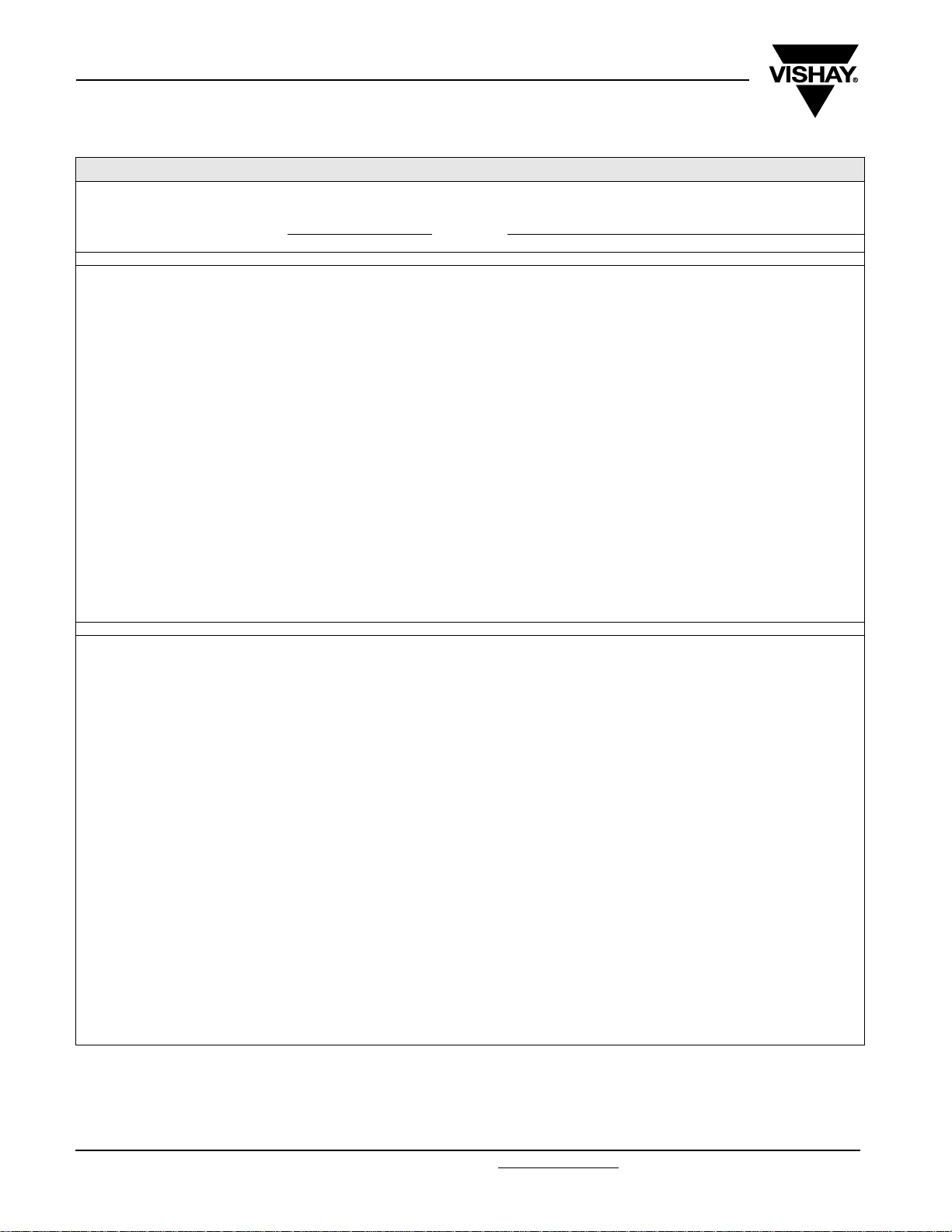
DIMENSIONS in inches [millimeters]
1.750
[44.45]
Min.
L
± 0.062 [1.57]
1.750
[44.45]
Min.
Humidity Test: 95 % relative humidity at + 40 °C for 250
hours. No visible damage.
Maximum
Minimum IR = 20 % of initial limit
Maximum DF = 0.12 %
AC Life Test: 110 % of rated rms voltage at 60 Hz for 1000
hours at + 85 °C.
Maximum Δ CAP ± 5 %
Minimum IR = 50 % of initial limit
Maximum DF = 0.12 %
Δ CAP ± 1.0 %
PHYSICAL CHARACTERISTICS
Lead Pull: 5 pounds (2.3 kilograms) for one minute. No
physical damage.
Lead Bend: After three complete consecutive bends. No
damage.
Marking: Sprague
capacitance and voltage.
®
trademark, type or part number,
D
Max.
Solid Tinned Wire
0.032 [0.81] Nominal Dia.
(No. 20 AWG)
* Leads to be within 0.062" [1.57 mm] of center line at egrees but not less than 0.031" [0.79 mm] from edge.
Document Number: 42029 For technical questions, contact: spresale@vishay.com
Revision: 07-Feb-07 25
www.vishay.com
Type 730P
Not for New Design
Vishay Sprague
Film Capacitors
High Frequency, Wrap-and-Fill,
Metallized Polypropylene
STANDARD RATINGS in inches [millimeters]
ESR
CAPACITANCE
(µF) PART NUMBER**
0.22 730P224X9100 0.275 [7.0] 0.75 [19.0] -
0.27 730P274X9100 0.298 [7.6] 0.75 [19.0] -
0.33 730P334X9100 0.324 [8.2] 0.75 [19.0] -
0.39 730P394X9100 0.347 [8.8] 0.75 [19.0] - - - - - - - -
0.47* 730P474X9100 0.376 [9.6] 0.75 [19.0] 37.0 3.7 3.4 3.1 2.8 2.5 2.0 1.4
0.56 730P564X9100 0.321 [8.2] 1.00 [25.4] 35.0 3.9 3.6 3.3 2.9 2.6 2.1 1.5
0.68 730P684X9100 0.348 [8.8] 1.00 [25.4] 33.0 4.1 3.8 3.5 3.1 2.8 2.2 1.6
0.82 730P824X9100 0.377 [9.6] 1.00 [25.4] 31.0 4.3 4.0 3.6 3.2 2.9 2.3 1.7
1.0* 730P105X9100 0.421 [10.7] 1.00 [25.4] 26.0 5.5 5.1 4.7 4.2 3.6 2.8 2.6
1.2 730P125X9100 0.454 [11.5] 1.00 [25.4] 24.0 5.7 5.3 4.9 4.4 3.8 3.0 2.8
1.5 730P155X9100 0.500 [12.7] 1.00 [25.4] 20.0 6.1 5.5 5.1 4.6 4.0 3.2 3.1
1.8 730P185X9100 0.541 [13.7] 1.00 [25.4] 19.0 6.3 5.7 5.3 4.8 4.1 3.4 3.0
2.0 730P205X9100 0.486 [12.3] 1.25 [31.8] 18.0 6.5 6.0 5.5 4.9 4.2 3.5 3.2
2.2 730P225X9100 0.507 [12.9] 1.25 [31.8] 18.0 6.8 6.3 5.7 5.1 4.4 3.6 3.3
2.7 730P275X9100 0.554 [14.1] 1.25 [31.8] 17.0 7.1 6.5 6.0 5.3 4.6 3.7 3.4
3.0 730P305X9100 0.581 [14.8] 1.25 [31.8] 16.0 7.3 6.7 6.2 5.5 4.8 3.9 3.5
3.3 730P335X9100 0.606 [15.4] 1.25 [31.8] 16.0 7.4 6.8 6.4 5.6 4.9 4.0 3.6
3.9 730P395X9100 0.654 [16.6] 1.25 [31.8] 15.0 7.6 6.9 6.6 5.8 5.1 4.1 3.7
4.0 730P405X9100 0.537 [13.6] 1.75 [44.5] 15.0 7.8 7.0 6.7 5.9 5.2 4.2 3.8
4.7 730P475X9100 0.577 [14.7] 1.75 [44.5] 15.0 8.1 7.4 6.8 6.0 5.3 4.3 3.9
5.0 730P505X9100 0.593 [15.1] 1.75 [44.5] 14.0 8.3 7.6 7.0 6.2 5.4 4.4 4.0
5.6 730P565X9100 0.624 [15.8] 1.75 [44.5] 14.0 8.4 7.7 7.1 6.4 5.5 4.5 4.1
6.0 730P605X9100 0.644 [16.4] 1.75 [44.5] 14.0 8.5 7.8 7.2 6.5 5.6 4.6 4.2
6.8 730P685X9100 0.682 [17.3] 1.75 [44.5] 13.0 8.5 8.0 7.4 6.7 5.7 4.7 4.3
8.0 730P805X9100 0.735 [18.7] 1.75 [44.5] 13.0 8.6 8.3 7.7 6.8 6.0 4.8 4.4
8.2 730P825X9100 0.743 [18.9] 1.75 [44.5] 13.0 8.8 8.6 8.0 7.0 6.1 4.9 4.5
10.0 730P106X9100 0.815 [20.7] 1.75 [44.5] 12.0 9.0 9.0 8.5 7.6 6.6 5.4 4.9
0.1* 730P104X9250 0.279 [7.1] 0.75 [19.0] -
0.12 730P124X9250 0.300 [7.6] 0.75 [19.0] -
0.15 730P154X9250 0.327 [8.3] 0.75 [19.0] -
0.18 730P184X9250 0.353 [9.0] 0.75 [19.0] -
0.22* 730P224X9250 0.306 [7.8] 1.00 [25.4] -
0.27 730P274X9250 0.333 [8.5] 1.00 [25.4] -
0.33* 730P334X9250 0.362 [9.2] 1.00 [25.4] -
0.39 730P394X9250 0.389 [9.9] 1.00 [25.4] - - - - - - - -
0.47* 730P474X9250 0.422 [10.7] 1.00 [25.4] 35.0 3.8 3.7 3.6 3.4 2.9 2.4 1.7
0.56 730P564X9250 0.464 [11.8] 1.00 [25.4] 33.0 3.9 3.8 3.7 3.5 3.1 2.5 1.8
0.68 730P684X9250 0.425 [10.8] 1.25 [31.8] 32.0 4.0 3.9 3.8 3.7 3.2 2.6 1.9
0.82 730P824X9250 0.471 [12.0] 1.25 [31.8] 31.0 4.2 4.1 4.0 3.9 3.4 2.8 2.0
1.0* 730P105X9250 0.513 [13.0] 1.25 [31.8] 28.0 4.4 4.4 4.4 4.4 4.3 3.5 3.2
1.2 730P125X9250 0.554 [14.1] 1.25 [31.8] 27.0 4.7 4.6 4.5 5.0 4.5 3.7 3.3
1.5 730P155X9250 0.613 [15.6] 1.25 [31.8] 26.0 5.1 5.0 4.9 5.4 4.7 3.9 3.5
1.8 730P185X9250 0.667 [17.0] 1.25 [31.8] 25.0 5.9 5.8 5.7 5.7 5.0 4.1 3.7
2.0* 730P205X9250 0.700 [17.8] 1.25 [31.8] 21.0 7.2 7.2 6.8 6.0 5.2 4.3 3.9
2.2 730P225X9250 0.610 [15.5] 1.75 [44.5] 20.0 8.4 7.5 7.0 6.3 5.4 4.5 4.1
2.7 730P275X9250 0.669 [17.0] 1.75 [44.5] 19.0 8.6 7.8 7.3 6.6 5.7 4.7 4.3
3.0 730P305X9250 0.703 [17.9] 1.75 [44.5] 18.0 9.0 8.3 7.6 6.8 5.9 4.8 4.4
3.3 730P335X9250 0.734 [18.6] 1.75 [44.5] 18.0 9.0 8.4 7.8 7.0 6.0 4.9 4.5
3.9 730P395X9250 0.794 [20.2] 1.75 [44.5] 17.0 9.0 8.5 8.0 7.2 6.2 5.0 4.6
4.0 730P405X9250 0.803 [20.4] 1.75 [44.5] 16.0 9.0 8.6 8.2 7.4 6.3 5.1 4.7
4.7 730P475X9250 0.866 [22.0] 1.75 [44.5] 16.0 9.0 8.8 8.5 7.7 6.6 5.3 4.9
5.0 730P505X9250 0.892 [22.7] 1.75 [44.5] 15.0 9.0 9.0 8.8 7.9 6.8 5.6 5.1
5.6 730P565X9250 0.941 [23.9] 1.75 [44.5] 15.0 9.0 9.0 8.9 8.0 7.0 5.8 5.3
6.0 730P605X9250 0.972 [24.7] 1.75 [44.5] 15.0 9.0 9.0 9.0 8.2 7.2 5.9 5.5
6.8 730P685X9250 0.882 [22.4] 2.25 [57.2] 15.0 9.0 9.0 9.0 8.4 7.4 6.0 5.6
8.0 730P805X9250 0.953 [24.2] 2.25 [57.2] 14.0 9.0 9.0 9.0 8.7 7.8 6.3 5.8
8.2 730P825X9250 0.964 [24.5] 2.25 [57.2] 14.0 9.0 9.0 9.0 8.8 7.9 6.4 5.9
10.0 730P106X9250 1.060 [26.9] 2.25 [57.2] 13.0 9.0 9.0 9.0 8.9 8.3 6.8 6.2
* These ratings are stocked.
** Part Numbers listed are for a capacitance tolerance of ± 10 %. To specifiy ± 20 % tolerance, change the “X9” in the Part Number to “X0”;
for ± 5 %, from “X9” to “X5”.
*** The peak current pulse capability ot these capacitors is 10 amperes/µF. The maximum rate voltage change is 10 V/µS.
CASE SIZE
D L + 25 °C + 35 °C + 45 °C + 55 °C + 65 °C + 75 °C + 85 °C
(Milliohms)
20 kHz 100 Khz
100 WVDC
Not applicable. These capacitance values are not customarily
250 WVDC
Not applicable. These capacitance values are not customarily
MAXIMUM RIPPLE CURRENT
(Amps rms) at 20 kHz
Case Temperature*** at
used in switched-mode power supplies.
used in switched-mode power supplies.
www.vishay.com For technical questions, contact: spresale@vishay.com Document Number: 42029
26 Revision: 07-Feb-07

Not for New Design
Type 730P
Film Capacitors
Vishay Sprague
High Frequency, Wrap-and-Fill,
Metallized Polypropylene
STANDARD RATINGS in inches [millimeters]
ESR
CAPACITANCE
(µF)
0.047 730P473X9400 0.258 [6.6] 0.75 [19.0] -
0.056 730P563X9400 0.275 [7.0] 0.75 [19.0] -
0.068 730P683X9400 0.297 [7.5] 0.75 [19.0] -
0.082 730P823X9400 0.320 [8.1] 0.75 [19.0] -
0.1* 730P104X9400 0.348 [8.8] 0.75 [19.0] -
0.12 730P124X9400 0.299 [7.6] 1.00 [25.4] -
0.15* 730P154X9400 0.328 [8.3] 1.00 [25.4] -
0.18 730P184X9400 0.353 [9.0] 1.00 [25.4] -
0.22 730P224X9400 0.385 [9.8] 1.00 [25.4] -
0.27 730P274X9400 0.421 [10.7] 1.00 [25.4] -
0.33 730P334X9400 0.469 [11.9] 1.00 [25.4] -
0.39 730P394X9400 0.503 [12.8] 1.00 [25.4] - - - - - - - -
0.47* 730P474X9400 0.545 [13.8] 1.00 [25.4] 32.0 5.7 5.5 5.0 4.4 3.8 3.2 2.2
0.56 730P564X9400 0.506 [12.9] 1.25 [31.8] 31.0 5.7 5.7 5.3 4.4 4.1 3.3 2.3
0.68 730P684X9400 0.551 [14.0] 1.25 [31.8] 30.0 5.7 5.7 5.5 4.8 4.3 3.5 2.4
0.82 730P824X9400 0.599 [15.2] 1.25 [31.8] 28.0 5.7 5.7 5.6 5.3 4.5 3.7 2.6
1.0* 730P105X9400 0.655 [16.6] 1.25 [31.8] 27.0 5.7 5.7 5.7 5.7 5.7 4.7 4.3
1.2 730P125X9400 0.712 [18.1] 1.25 [31.8] 26.0 6.3 6.2 6.0 5.9 5.8 4.9 4.5
1.5 730P155X9400 0.658 [16.7] 1.75 [44.5] 25.0 7.0 6.9 6.7 6.6 6.5 5.2 4.7
1.8 730P185X9400 0.716 [18.2] 1.75 [44.5] 23.0 8.0 7.9 7.8 7.7 6.8 5.5 5.0
2.0* 730P205X9400 0.752 [19.1] 1.75 [44.5] 21.0 9.0 9.0 9.0 8.0 7.0 5.7 5.2
2.2 730P225X9400 0.786 [20.0] 1.75 [44.5] 20.0 9.0 9.0 9.0 8.3 7.4 5.9 5.4
2.7 730P275X9400 0.865 [22.0] 1.75 [44.5] 19.0 9.0 9.0 9.0 8.6 7.6 6.0 5.6
3.0* 730P305X9400 0.909 [23.1] 1.75 [44.5] 17.0 9.0 9.0 9.0 9.0 7.9 6.4 5.9
3.3 730P335X9400 0.951 [24.2] 1.75 [44.5] 16.0 9.0 9.0 9.0 9.0 8.1 6.6 6.3
3.9 730P395X9400 1.031 [26.2] 1.75 [44.5] 15.0 9.0 9.0 9.0 9.0 8.3 6.8 6.5
0.022* 730P223X9630 0.283 [7.2] 0.75 [19.0] -
0.027 730P273X9630 0.307 [7.8] 0.75 [19.0] -
0.033 730P333X9630 0.334 [8.5] 0.75 [19.0] -
0.039 730P393X9630 0.358 [9.1] 0.75 [19.0] -
0.047 730P473X9630 0.388 [9.9] 0.75 [19.0] -
0.056 730P563X9630 0.418 [10.6] 0.75 [19.0] -
0.068 730P683X9630 0.346 [8.8] 1.00 [25.4] -
0.082 730P823X9630 0.374 [9.5] 1.00 [25.4] -
0.1 730P104X9630 0.408 [10.4] 1.00 [25.4] -
0.12 730P124X9630 0.443 [11.3] 1.00 [25.4] -
0.15 730P154X9630 0.496 [12.6] 1.00 [25.4] -
0.18 730P184X9630 0.538 [13.7] 1.00 [25.4] -
0.22 730P224X9630 0.496 [12.6] 1.25 [31.8] -
0.27 730P274X9630 0.542 [13.8] 1.25 [31.8] -
0.33 730P334X9630 0.593 [15.1] 1.25 [31.8] -
0.39 730P394X9630 0.639 [16.2] 1.25 [31.8] - - - - - - - -
0.47 730P474X9630 0.696 [17.7] 1.25 [31.8] 28.0 6.8 6.3 5.8 5.2 4.5 3.6 2.6
0.56 730P564X9630 0.608 [15.4] 1.75 [44.5] 26.0 7.4 6.9 6.3 5.6 4.8 4.0 2.8
0.68 730P684X9630 0.664 [16.9] 1.75 [44.5] 25.0 7.8 7.2 6.6 5.9 5.1 4.2 2.9
0.82 730P824X9630 0.724 [18.4] 1.75 [44.5] 22.0 8.1 7.5 6.9 6.2 5.3 4.3 3.1
1.0* 730P105X9630 0.794 [20.2] 1.75 [44.5] 18.0 8.6 7.9 7.3 6.5 5.6 4.6 3.6
* These ratings are stocked.
** Part Numbers listed are for a capacitance tolerance of ± 10 %. To specifiy ± 20 % tolerance, change the “X9” in the Part Number to “X0”;
for ± 5 %, from “X9” to “X5”.
*** The peak current pulse capability ot these capacitors is 10 amperes/µF. The maximum rate voltage change is 10 V/µS.
PART
NUMBER**
CASE SIZE
D L + 25 °C + 35 °C + 45 °C + 55 °C + 65 °C + 75 °C + 85 °C
(Milliohms)
20 kHz 100 Khz
400 WVDC
630 WVDC
Not applicable. These capacitance values are not customarily
Not applicable. These capacitance values are not customarily
MAXIMUM RIPPLE CURRENT
(Amps rms) at 20 kHz
Case Temperature*** at
used in switched-mode power supplies.
used in switched-mode power supplies.
ORDERING INFORMATION
730P 224 X9 100
TYPE CAPACITANCE CAPACITANCE TOLERANCE DC VOLTAGE RATING*
This is expressed in picofarads. The first two
digits are the significant figures. The third is
the number of zeros to follow.
* At + 85 °C, AC rms ratings for frequencies up to and including 400 Hz correspond to this table:
WVDC 100 250 400 630
RATED rms VOLTS 70 175 275 275
Document Number: 42029 For technical questions, contact: spresale@vishay.com
Revision: 07-Feb-07 27
X0 = ± 20 %
X9 = ± 10 %
X5 = ± 5 %
This is expressed in volts.
www.vishay.com

Legal Disclaimer Notice
Vishay
Notice
Specifications of the products displayed herein are subject to change without notice. Vishay Intertechnology, Inc.,
or anyone on its behalf, assumes no responsibility or liability for any errors or inaccuracies.
Information contained herein is intended to provide a product description only. No license, express or implied, by
estoppel or otherwise, to any intellectual property rights is granted by this document. Except as provided in Vishay's
terms and conditions of sale for such products, Vishay assumes no liability whatsoever, and disclaims any express
or implied warranty, relating to sale and/or use of Vishay products including liability or warranties relating to fitness
for a particular purpose, merchantability, or infringement of any patent, copyright, or other intellectual property right.
The products shown herein are not designed for use in medical, life-saving, or life-sustaining applications.
Customers using or selling these products for use in such applications do so at their own risk and agree to fully
indemnify Vishay for any damages resulting from such improper use or sale.
Document Number: 91000 www.vishay.com
Revision: 08-Apr-05 1
 Loading...