

Page 1
20 (0.79) REF.
5.8 (0.23) REF.
9.8 (0.39) REF.
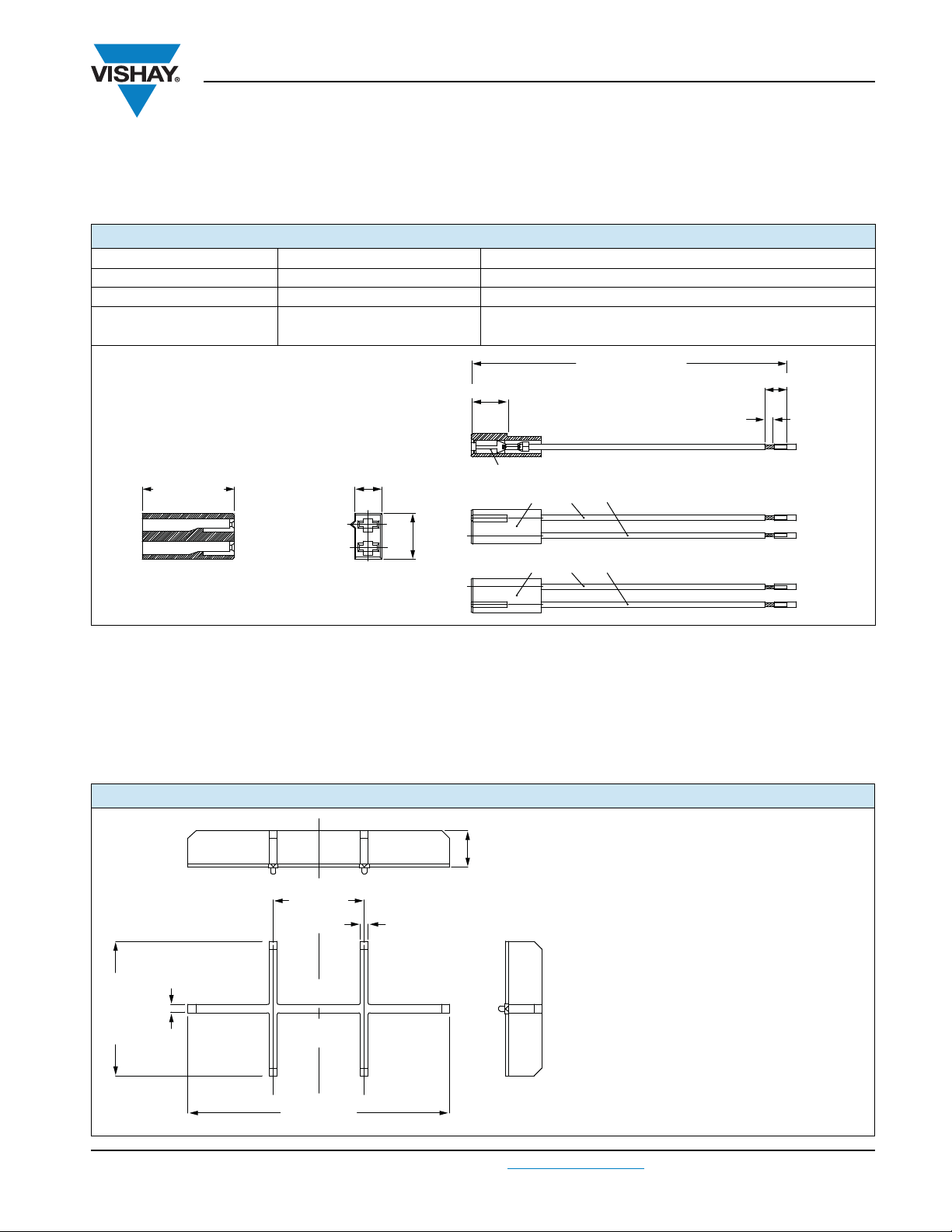
2 ways polarized connector housing,
dimensional detail
350 ± 5 (13.8 ± 0.20)
2.5 (0.10) MAX.
6.5 (0.26) REF.
10.5 (0.41) REF.
(3)
(5) (1) (2)
Layout
(4) (2) (1)
Layout
- DX
- SX
23 ± 0.5
(0.91 ± 0.02)
2 ± 0.3
(0.08 ± 0.01)
8.5 (0.34)
66 ± 0.3
(2.6 ± 0.01)
34 ± 0.3
(1.34 ± 0.01)
2 ± 0.3
(0.08 ± 0.01)
Ident No. 6444.0211.AA for all MT..KB Series
Barriers mounting instructions
Coat uniformly the groove on the plastic box
with a silicon adhesive. Insert the barriers into
the groove on the plastic box. Cure the silicon
adhesive according to its technical notes.
We suggest the use of DOW CORNING
Silastic 744RTV (time curing 30 minutes at
room temperature).
Optional Hardware
Vishay Semiconductors
Optional Hardware
MT..KB SERIES
GATE LEADS in millimeters (inches)
IDENT NO. DEVICE SERIES DESCRIPTION
6443.2112.AA 51, 91, 111MT..KB 2 DX connectors with yellow and white leads
6443.2113.AA 52, 92, 112MT..KB 1 SX + 1 DX connectors with yellow and white leads
6443.2114.AA
53, 93, 113MT..KB
54, 94, 104MT..KB
1 SX + 2 DX connectors with yellow and white leads
Notes
(1)
Tinned copper stranded cable, UL 758, style 1558, AWG 22 (0.32 mm2) lay 19 x 0.16 ETFE insulation yellow color, ext. dia. 1.25 mm,
temperature rating 125 °C
(2)
Same as note
where is not placed the polarization key
(3)
Receptacle fast-on terminal with locking lance, for 2.8 x 0.8 tab (series 110) ref. PN. AMP 150571-2 or equivalent
(4)
2 ways polarized connector housing, as shown on dimensional detail (the represented version refers to left “SX” connector housing)
Raw material: PBT ciba crastine SK645FR, black color
(5)
Connector housing as note
BARRIERS in millimeters (inches)
Document Number: 95172 For technical questions, contact: indmodules@vishay.com
Revision: 23-Sep-08 1
(1)
, but with white color insulation. Concerning the configurations in which white cable is requested, it must be connected
(4)
, right “DX” version
www.vishay.com
Page 2
Optional Hardware
Vishay Semiconductors
Optional Hardware
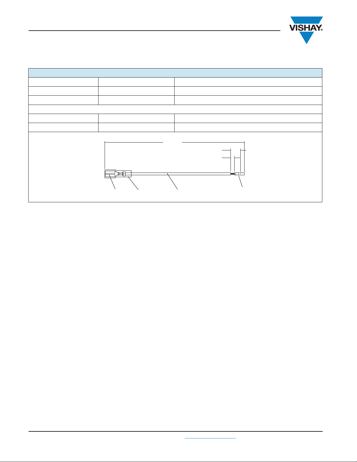
ADD-A-PAK SERIES
CATHODE AND GATE LEADS
IDENT NO. DEVICE SERIES DESCRIPTION
6443.2115.AA VSKT.. - VSKU.. - VSKV.. 2 yellow gate leads + 2 red cathode leads
6443.2116.AA VSKH.. - VSKL.. 1 yellow gate lead + 1 red cathode lead
WITHOUT AUXILIARY CATHODE
6443.2117.AA VSKT.. 2 yellow gate leads
6443.2118.AA VSKH.. - VSKL.. 1 yellow gate lead
300 ± 5
6.5
2.5 MAX.
Cut insulation
end piece 6.5 mm
(3)
Layout
(4)
(1) (2)
Notes
(1)
Tinned copper stranded cable, UL 758, style 1558, AWG 22 (0.32 mm2) lay 19 x 0.16 ETFE insulation yellow color, ext. dia. 1.25 mm,
temperature rating 125 °C
(2)
Same as note
(3)
Receptacle fast-on terminal, for 2.8 x 0.8 tab (series 110) ref. PN. AMP 180420-2 or equivalent
(4)
Fast-on cover for receptacle terminal series 2.8 in nylon 66 material natural color, temperature 105 °C
(1)
, but with red color insulation
www.vishay.com For technical questions, contact: indmodules@vishay.com
2 Revision: 23-Sep-08
Document Number: 95172
Page 3

20 (0.79) REF.
5.8 (0.23) REF.
9.8 (0.39) REF.
2 ways polarized connector housing,
dimensional detail
350 ± 5 (13.8 ± 0.20)
2.5 (0.10) MAX.
6.5 (0.26) REF.
10.5 (0.41) REF.
(3)
(5) (1) (2)
Layout
(4) (2) (1)
Layout
- DX
- SX
Optional Hardware
Optional Hardware
Vishay Semiconductors
MAGN-A-PAK SERIES, SUPER MAGN-A-PAK SERIES
CATHODE AND GATE LEADS in millimeters (inches)
IDENT NO. DEVICE SERIES DESCRIPTION
6443.2119.AA VSKT.. - VSKU.. - VSKV.. 1 SX + 1 DX connectors with red and yellow leads
6443.2120.AA VSKH.. - VSKN.. 1 SX connector with red and yellow leads
6443.2121.AA VSKL.. - VSKK.. 1 DX connector with red and yellow leads
Notes
(1)
Tinned copper stranded cable, UL 758, style 1558, AWG 22 (0.32 mm2) lay 19 x 0.16 ETFE insulation yellow color, ext. dia. 1.25 mm,
temperature rating 125 °C
(2)
Same as note
where is not placed the polarization key
(3)
Receptacle fast-on terminal with locking lance, for 2.8 x 0.8 tab (series 110) ref. PN. AMP 150571-2 or equivalent
(4)
2 ways polarized connector housing, as shown on dimensional detail (the represented version refers to left “SX” connector housing)
Raw material: PBT ciba crastine SK645FR, black color
(5)
Connector housing as note
(1)
, but with white color insulation. Concerning the configurations in which white cable is requested, it must be connected
(4)
, right “DX” version
Document Number: 95172 For technical questions, contact: indmodules@vishay.com
Revision: 23-Sep-08 3
www.vishay.com
Page 4

Optional Hardware
20 (0.79) REF.
5.8 (0.23) REF.
9.8 (0.39) REF.
2 ways polarized connector housing,
dimensional detail
350 ± 5 (13.8 ± 0.20)
2.5 (0.10) MAX.
6.5 (0.26) REF.
10.5 (0.41) REF.
(3)
(5) (1) (2)
Layout
(4) (2) (1)
Layout
- DX
- SX
Vishay Semiconductors
Optional Hardware
INT-A-PAK SERIES
CATHODE AND GATE LEADS in millimeters (inches)
IDENT NO. DEVICE SERIES DESCRIPTION
6443.2119.AA VSKT.. - VSKU.. - VSKV.. 1 SX + 1 DX connectors with red and yellow leads
6443.2120.AA VSKH.. - VSKN.. 1 SX connector with red and yellow leads
6443.2121.AA VSKL.. - VSKK.. 1 DX connector with red and yellow leads
Notes
(1)
Tinned copper stranded cable, UL 758, style 1558, AWG 22 (0.32 mm2) lay 19 x 0.16 ETFE insulation yellow color, ext. dia. 1.25 mm,
temperature rating 125 °C
(2)
Same as note
where is not placed the polarization key
(3)
Receptacle fast-on terminal with locking lance, for 2.8 x 0.8 tab (series 110) ref. PN. AMP 150571-2 or equivalent
(4)
2 ways polarized connector housing, as shown on dimensional detail (the represented version refers to left “SX” connector housing)
Raw material: PBT ciba crastine SK645FR, black color
(5)
Connector housing as note
SCREWS AND SPACERS in millimeters (inches)
Conical washer
M6 DIN 6908
Stamp Phillips
Size nr. 3
Depth 3, 1 - 3, 4
www.vishay.com For technical questions, contact: indmodules@vishay.com
4 Revision: 23-Sep-08
(1)
, but with white color insulation. Concerning the configurations in which white cable is requested, it must be connected
(4)
, right “DX” version
Ident No. 6447.0266.AA for all INT-A-PAK series
3 screws M6 x 1
21 (0.82) length
47 (1.9)
30
41 (1.6)
(1.18)
1
Spacers
14.5 (0.57) DIA. 11 (0.43) thickness
Packaging: Polietylene bag
Quantity: 9 pieces
32
3 spacers
6
7
4
5
2 (0.08)
M6 x 1 - 6g
14 (0.55)
Ø 12 - 0.5
(Ø 0.47 - 0.02)
+ 0.2
(0.15 )
4
- 0.1
21 ± 0.2
Ø 6.76 (Ø 0.26)
+ 0.007
- 0.004
(0.82 ± 0.007)
11
(0.43)
Ø 14.5 ± 0.5
(Ø 0.57 ± 0.02)
Ø 6.5 (Ø 0.25)
Screws
M6 x 1 scews 21 (0.82) length
Packaging: Polietylene bag
Quantity: 9 pieces
Document Number: 95172
 Loading...