

www.vishay.com
89
RT230
Vishay Sfernice
Document Number: 50029
Revision 22-Jun-05
For technical questions, contact sfer@vishay.com
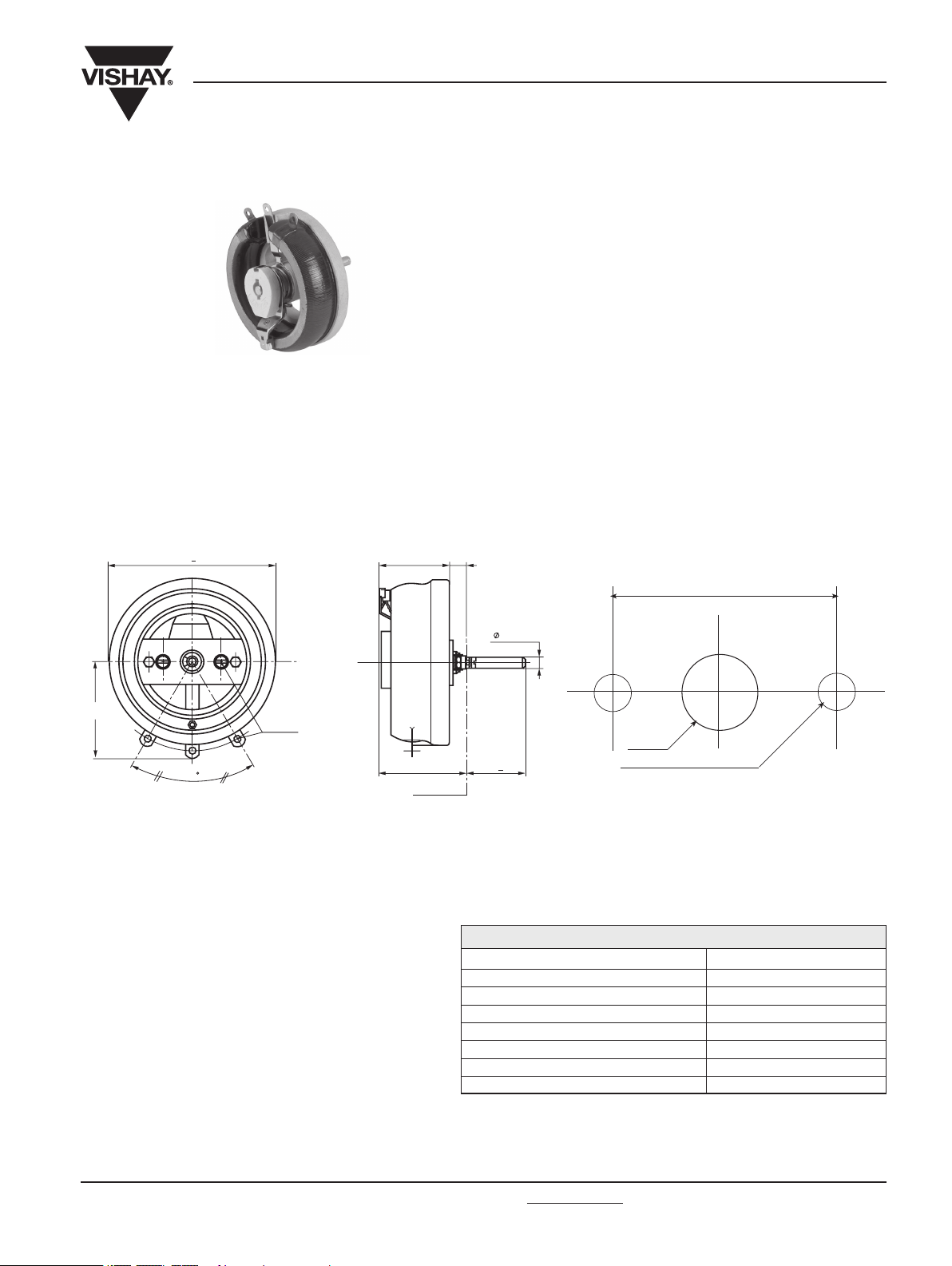
Wirewound Rheostat/Potentiometer
FEATURES
• 250 Watt at 25°C
• CCTU 05-03B (PA7)
• Vitreous style
RT230-PA7 PANEL CUT OUT DETAILS
MECHANICAL SPECIFICATIONS
Mechanical Protection Vitreous
Mechanical Travel
300° ± 5°
Operating Torque
1 to 50 Ncm
End Stop Torque
200 Ncm
Unit Weight
1300 g
ENVIRONMENTAL SPECIFICATIONS
Temperature Range – 55°C + 320°C
Climatic Category
CCTU 454
CEI 55/200/56
ELECTRICAL SPECIFICATIONS
Ohmic Range 1Ω to 22kΩ
Tolerance Standard ± 10%
Power Rating 250 W at 25°C
Variation Law Standard linear
On request sectorial winding
Limiting Element Voltage 1500V
Dielectric Strength 2000VRMS
Insulation Resistance 103MΩ(500Vcc)
DIMENSIONS in millimeters
50
Ø 12
2 holes Ø 5.5
+
83
60
Screw M5
143 3,5
+
- 0
10 - 0, 05
75
50 2
AS
60 15
Mounting side
Document Number: 50029
Revision 22-Jun-05
www.vishay.com
90
RT230
Vishay Sfernice
For technical questions, contact sfer@vishay.com
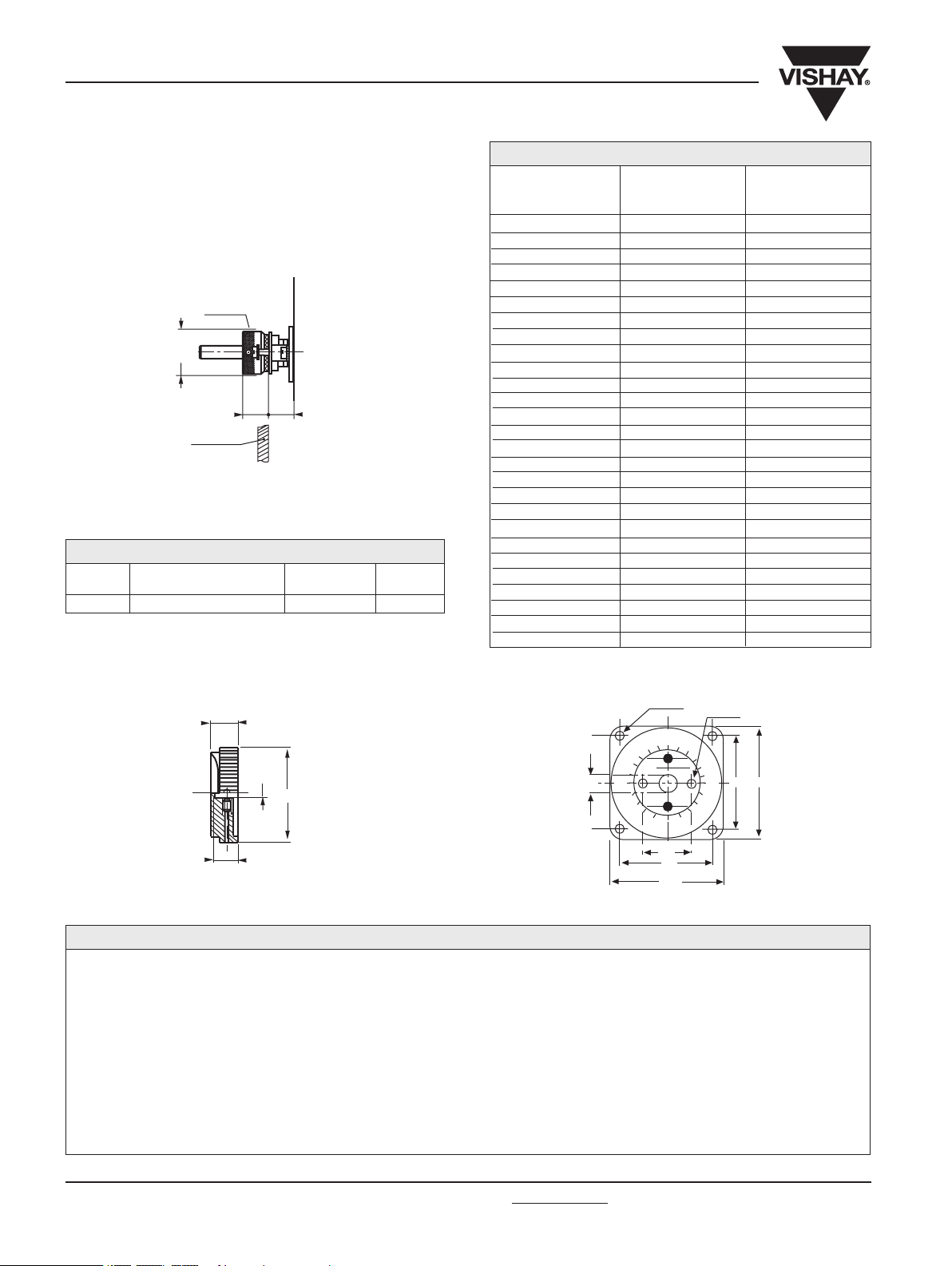
LOCKING DEVICE
This is supplied as an option.
The available spindle length is according to the panel
thick-ness.
Order reference : DBA10.
NOMINAL
RESISTANCE
Ω
MAX. SERVICE
VOLTAGE
V
MAX. CURRENT
THROUGH WIPER
A
1
1.5
2.2
3.3
4.7
6.8
10
15
22
33
47
68
100
150
220
330
470
680
1k
1.5k
2.2k
3.3k
4.7k
6.8k
10k
15k
22k
15.2
18.6
22.5
27.6
32.9
31.5
48
58.7
71.1
87.1
104
125
152
186
225
276
329
395
480
587
711
871
1040
1250
1500
1940
2000
15.2
12.4
10.2
8.36
7
5.82
4.80
3.92
3.23
2.64
2.21
1.84
1.52
1.24
1.02
0.836
0.700
0.582
0.480
0.392
0.323
0.264
0.221
0.184
0.150
0.13
0.091
PARTICULAR CHARACTERISTICS
For any special requirement on request : spindle flats, etc.
Please supply detailed drawing.
Ø
mm
10
WITHOUT
AS50
SCREW DRIVER
SLOT
CODE
DISTANCE TO MOUNTING
PLATE MM
SPINDLES
Wirewound Rheostat/Potentiometer
SERIES
STYLE
SPINDLE
LOCKING
DEVICE
VARIATION
LAW
ACC
60JF
CG115 XXX
SPECIAL
DESIGN
Method N°
Optional
OHMIC
VALUE
SPINDLE
(Code)
WINDING
RT
230
Optional
Optional
L
10kΩ
AS
for special
spindles
please supply
detailed drawing
± 10%
OPTIONS
VITREOUS
ORDERING PROCEDURE
TOLERANCE
MODEL KNOB
DIAL OTHER SPECIAL
REQUIREMENTS
COMMAND KNOB 60JF (OPTION) DIAL CG115 (OPTION)
4 holes Ø 3.5
Ø 12
5
6
7
8
9
10
0
1
2
3
4
115
98
2 holes Ø 6
98
50
115
MARKING
SFERNICE trademark, series, style, ohmic value (in Ω or kΩ), tolerance (in %), maximum current in A, manufacturing date
21
Ø 76
Ø 10
16
thumb
wheel nut
min. panel cut-out
Ø 32
panel
18
17

Legal Disclaimer Notice
Vishay
Notice
Specifications of the products displayed herein are subject to change without notice. Vishay Intertechnology, Inc.,
or anyone on its behalf, assumes no responsibility or liability for any errors or inaccuracies.
Information contained herein is intended to provide a product description only. No license, express or implied, by
estoppel or otherwise, to any intellectual property rights is granted by this document. Except as provided in Vishay's
terms and conditions of sale for such products, Vishay assumes no liability whatsoever, and disclaims any express
or implied warranty, relating to sale and/or use of Vishay products including liability or warranties relating to fitness
for a particular purpose, merchantability, or infringement of any patent, copyright, or other intellectual property right.
The products shown herein are not designed for use in medical, life-saving, or life-sustaining applications.
Customers using or selling these products for use in such applications do so at their own risk and agree to fully
indemnify Vishay for any damages resulting from such improper use or sale.
Document Number: 91000 www.vishay.com
Revision: 08-Apr-05 1
 Loading...