

Page 1

WEIGH SYSTEM TECHNOLOGY
BLH
DXP10/15 Weigh Transmitters
Operator’s Manual
TM002
RevG
6/1/11
Doc 35102
Page 2

NOTICE
BLH makes no representation or warranties of any kind whatsoever with respect to the
contents hereof and specifically disclaims any implied warranties or merchantability or
fitness for any particular purpose. BLH shall not be held liable for errors contained herein
or for incidental or consequential damages in connection with the furnishing,
performance, or use of this publication or its contents.
BLH reserves the right to revise this manual at any time and to make changes in the
contents hereof without obligation to notify any person of such revision or changes.
Call (781) 298-2216 for BLH Field Service
Page 3

Table of Contents
SECTION 1. General Information ...................................................................................................................... 1-1
1.1 INTRODUCTION ...................................................................................................................................... 1-1
1.1.1 General Description. ............................................................................................................................. 1-1
1.1.2 Standard Instrument. ............................................................................................................................ 1-1
1.2 OPTIONS ................................................................................................................................................. 1-1
1.2.1 Mounting Options. ................................................................................................................................ 1-1
1.2.2 Optional Terminal Computer Interface. ................................................................................................ 1-1
1.2.3 Optional Modbus RTU Interface. .......................................................................................................... 1-2
1.2.4
Optional Fisher ProVox Protocol .......................................................................................................... 1-2
1.2.5 Optional Allen-Bradley Remote I/O ...................................................................................................... 1-2
1.2.6 Analog Option. ...................................................................................................................................... 1-2
1.2.7 Software Filter Option. .......................................................................................................................... 1-2
1.3 DXp-10/15 SPECIFICATIONS ................................................................................................................. 1-2
1.4 ORDERING SPECIFICATIONS ............................................................................................................... 1-4
1.5 WARRANTY POLICY ............................................................................................................................... 1-4
1.6 FIELD ENGINEERING ............................................................................................................................. 1-4
SECTION 2. Installation..................................................................................................................................... 2-1
2.1 INTRODUCTION ...................................................................................................................................... 2-1
2.1.1 General. ................................................................................................................................................ 2-1
2.2 MOUNTING .............................................................................................................................................. 2-1
2.2.1 Standard Units. ..................................................................................................................................... 2-1
2.2.2 Explosion-Proof and Division 2 Options. .............................................................................................. 2-1
2.3 ELECTRICAL ........................................................................................................................................... 2-2
2.3.1 Transducer Inputs. ................................................................................................................................ 2-2
2.3.2 Serial Communication. ......................................................................................................................... 2-2
2.3.3 Analog Output. ...................................................................................................................................... 2-3
2.3.4 Mains (AC) Power (Figure 2-4)............................................................................................................. 2-3
2.3.5 Auxiliary I/O Port. .................................................................................................................................. 2-3
SECTION 3. Configuration ................................................................................................................................ 3-1
3.1 GENERAL ................................................................................................................................................ 3-1
3.2 SET-UP .................................................................................................................................................... 3-1
3.2.1 Power Selection .................................................................................................................................... 3-1
3.2.2 Excitation Voltage. ................................................................................................................................ 3-1
3.2.3 Serial Format, Address, and Baud Rate. .............................................................................................. 3-1
3.2.4 Input Range Selection. ......................................................................................................................... 3-1
3.3 CALIBRATION .......................................................................................................................................... 3-1
iii
Page 4

3.3.1 Digital Calibration. ................................................................................................................................ 3-1
3.3.2 Analog Calibration. ............................................................................................................................... 3-2
3.3.3 Monitor Mode Calibration. .................................................................................................................... 3-2
3.3.4 LCp-40 Calibration. ............................................................................................................................... 3-2
3.4 CHECK CAL ............................................................................................................................................. 3-5
3.5 FILTER SELECTION ................................................................................................................................ 3-6
3.5.1 Standard Filter. ..................................................................................................................................... 3-6
3.5.2 Optional Digital Filtering. ...................................................................................................................... 3-6
3.6 Factory Default Calibration ....................................................................................................................... 3-7
SECTION 4. Serial Communication .................................................................................................................. 4-1
4.1 GENERAL ................................................................................................................................................ 4-1
4.1.1 LCp-40 Digi System Network. .............................................................................................................. 4-1
4.1.2 Standard Simplex Output (Continuous Output). ................................................................................... 4-1
4.1.3 Computer/Terminal Interface (Optional). .............................................................................................. 4-2
4.1.4 MODBUS BTU Protocol (Optional). ..................................................................................................... 4-4
4.1.5 Fisher ProVox Protocol (Optional) ........................................................................................................ 4-7
4.1.6 Allen-Bradley Remote I/O (Optional). ................................................................................................... 4-8
SECTION 5. Operation ...................................................................................................................................... 5-1
5.1 GENERAL ................................................................................................................................................ 5-1
5.2 GROSS WEIGHT WEIGHING ................................................................................................................. 5-1
5.3 ZERO OPERATION ................................................................................................................................. 5-1
5.4 NET WEIGHT WEIGHING ....................................................................................................................... 5-1
5.5 TARE OPERATION .................................................................................................................................. 5-1
5.6 ERROR DETECTION ............................................................................................................................... 5-1
5.7 CHECK CAL OPERATION ....................................................................................................................... 5-1
iv
Page 5

SECTION 1. General Information
1.1 INTRODUCTION
1.1.1 General Description
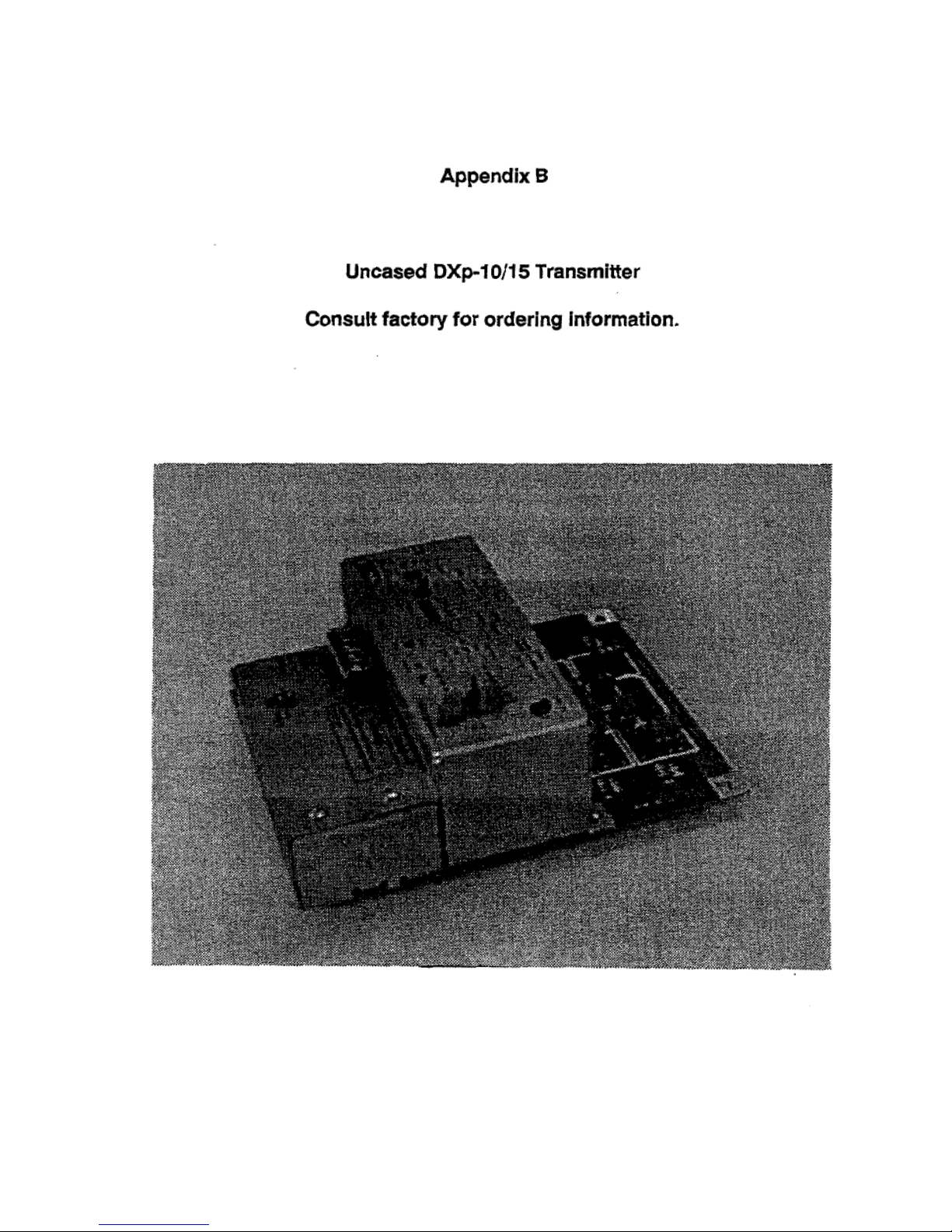
The DXp-10 and DXp-15 (Figure 1-1) are
microprocessor based weight transmitters. DXp10/15 transmitters sum and convert the millivolt
signal from up to four strain gage type load cells
into a digital and/or analog voltage or current
signal (up to eight cells can be summed using
an external 308A summing unit). Bridge
excitation voltage is factory selectable for 10 or
15 volts. Units are available in NEMA 4, NEMA
4X or explosion proof enclosures for field
mounting. The unit operates from either 110 or
220 VAC at 50/60 Hz, and is equipped with
screw terminal connections for power input, and
serial/analog outputs. Set-up and calibration is
per-formed using three internal switches (see
SECTION III). Communication baud rate and
instrument address values are selected via a
bank of internal DIP switches (see SECTION
III).
Class I, II, Division 2, Group A-G hazardous
location requirements and are optionally
available with FM and CSA approvals and
certifications.
1.2 OPTIONS
1.2.1 Mounting Options
For corrosive, hose down, or sanitary
environments, a NEMA 4X stainless steel
enclosure is available. An explosion proof
enclosure is available for Class I, II, Division 1,
Group B-G locations. Note: BLH 404 or 405
Intrinsic Safety Barriers must be specified for
weigh systems located in a Division I area.
The DXp-10 Transmitter performance
specifications are designed for inventory and
other static weighing applications where
moderate resolution and speed is required. The
DXp-15 Process Transmitter is equipped with
high performance circuitry that provides the
greater resolution and speed for dynamic
process applications. Externally and in regard to
set-up and operation, each model is identical
Using RS 485 serial communication protocol, up
to sixteen DXp transmitters can be networked to
an LCp-40, 41, or 42 Network Controller. The
serial format can also be configured to provide
point to point or network communication to a
customer supplied computer.
1.1.2 Standard Instrument
The standard instrument includes an RS 485
serial port with BLH Digi-System network or a
simplex output protocols, a four cell summing
circuit, 10 or 15 volt excitation, averaging filter,
and a NEMA 4 mild steel, painted enclosure.
Standard instruments are designed to meet
Figure 1-1. DXp-10 Weight Transmitter
1.2.2 Optional Terminal Computer
Interface.
The terminal/computer interface option provides
a simple mnemonic half-duplex ASCII
communications protocol via a built-in macro
language consisting of 1 to 3 character command
strings (reference Table 4-3).
This powerful feature allows direct keyboard
control (using easily remembered commands) of
1-1
Page 6

DXp-10/15 calibration, and programming or
recall of weight variables (gross, net, tare, zero,
etc.) An on-line help function is available by
transmitting an ASCII Ir.
Easily learned macro language syntax greatly
simplifies the writing of a host computer
communication interface (customer supplied).
1.2.3 Optional Modbus RTU
Interface.
The Modbus interface option provides a simple
seamless communication link to any PC, PLC or
DCS with a mod-bus RTU Driver Option. Use of
this industry standard protocol (see paragraph
4.1.4) eliminates the requirement for custom
software driver development.
1.2.4
DXp-15 transmitters may be ordered with the
Fisher ProVox protocol. ProVox protocol allows
the DXp-15 to interface directly with a Fisher
ProVox distributed control system (DCS).
Optional Fisher ProVox
Protocol
1.2.5 Optional Allen-Bradley Remote
I/O
Optional Allen-Bradley Remote I10 (RIO) allows
13Xp¬15 transmitters direct access to a PLC
master processor. In essence, DXp-15
transmitters become direct coprocessors with
the PLC. DXp-15 data is read directly into the
main ladder logic program without using BCD or
serial interface cards. A simple three wire RIO
network connection ties all units together, even if
multiple DXp15s are used. Within the RIO
network link, each DXp-15 is addressed as 1/4
'logical rack'. Since a PLC logical rack consists
of 128 input and 128 output bits (or points), DXp
units communicate 32 input and 32 output bits;
1/4 logical rack format. For a full description of
logical rack addressing and data
communications formatting, reference the Allen
Bradley Remote I/O technical manual, BLH part
number TM010.
1.2.6 Analog Option.
An optional analog output provides both a 4-20 mA
and a 0-10 VDC output representing the gross
weight value. The circuit uses a 12 bit D-A
converter providing up to 4096 counts of resolution.
The current output drives up to a 1000 ohm load
and the voltage output will operate with a 25,000
ohm minimum load resistance.
1.2.7 Software Filter Option.
The digital filtering option offers eight software
filtering selections. The filter algorithms dampen
noise by averaging successive A-D conversions.
Digital filtering allows East response to true
weight changes by setting limits on averaging
based upon the magnitude of signal change.
Filter selections are presented in SECTION III.
Note: BLH tech note TD-071 provides a full
discussion of filter operation.
1.3 DXp-10/15 SPECIFICATIONS
PERFORMANCE
Resolution:
DXp-10 20,000 counts
DXp-15 50,000 counts
Sensitivity
DXp-10 1.0 μV/count
DXp-15 0.5 μV/count
Full Scale Range 25 of 35 mV (selectable)
Dead Load Range 100%
Input Impedance 10 M-ohms, max.
Load Cell Excitation 10 V for up to eight 350 ohm load cells (250 mA)
(Factory Selectable) 15 V for up to six 350 ohm load cells (250 mA)
Linearity ± 0.01% of full scale
1-2
Page 7

Temperature Coefficient
Span 2ppm/°C
Zero ± 2ppm/°C
Common Mode Rel. 100 db or better at or below 35Hz
Normal Mode Rej. 100 db or better at or below 35Hz
Conversion Speed DXp-10 400 msec
DXp-15 50 msec
Environment
Operating Temperature -10 to 55°C (12 to 131°F)
Storage Temperature -20 to 85°C (-4 to 185°F)
Humidity 5 to 90% rh, non-condensing
Voltage 117/230 1: 15% 50/60 Hz
Power 10 watts max
Parameter Storage EEPROM
EMVRFI Shielded from typical industrial interference
ENCLOSURE
Dimensions (NEMA 414X) 11.5 x 8.0 x 4.3 HWD
Explosion Proof 12.875 x 10.875 x 8.188 HWD
OPTIONS
Isolated Analog Output
Type 12 bit Digital to Analog Conversion
Voltage 0 to 10 volt (25K ohm min load)
Current 4 to 20 mA (1000 ohm max load)
SERIAL COMMUNICATION
LCp-40 Network (Standard)
Type RS 485 Half Duplex (Multi-Drop)
Baud 56.7k
Simplex Data Output (Standard)
Interface Type RS 485 (Simplex)
Data Format Simplex ASCII Data
7 Data Bit
Even Parity
1 Stop Bit
Terminal/Computer Interface (Optional)
Interface Type RS 485 Half Duplex (Standard)
Baud 1200 or 9600
Protocol Duplex Command/Response Format
MODBUS RTU Protocol (Optional)
Fisher ProVox Protocol (Optional)
Allen-Bradley Remote I/O (Optional)
Consult factory for details
1-3
Page 8

1.4 ORDERING SPECIFICATIONS
DXp-10 or DXp-15 [M]-[C]-[P]-[S] Includes: RS 485 Serial Output
[M] Mounting
(1) NEMA 4 Painted — standard
(2) NEMA 4X Stainless Steel
(3) NEMA 7 & 9 Explosion-Proof Class I, H, Div. 1,2 Grp. B—G
(8) #1 & FM/CSA Approved [Class l, Div 2, Group ABCD FG]
(9) #2 & FM/CSA Approved [Class l, Div 2, Group ABCD FG]
[C] Communication
(1) RS 485 LCp-40 Network — standard
(2) RS 485 LCp-40 Network and Terminal/Computer Interface
(4) Allen Bradley Remote I/O (DXp-15 only)
(5) MODBUS RTU Protocol (D4-15 only)
[P]Process Output
(1) No Process Output — standard
(2) 0-10 V & 4-20 mA analog
[S]Software
(1) Standard
(2) Dynamic Digital Filtering (DXp-15 only)
apply beyond their normal span of life to any
1.5 WARRANTY POLICY
BLH warrants the products covered hereby to be
free from defects in material and workmanship.
BLH's liability under this guarantee shall be
limited to repairing or furnishing parts to replace,
f.o.b. point of manufacture, any parts which,
within three (3) years from date of shipment of
said product(s) from BLH's plant, fail because of
defective workmanship or material performed or
furnished by BLH. As a condition hereof, such
defects must be brought to BLH's attention for
verification when first discovered, and the
material or parts alleged to be defective shall be
returned to BLH if requested. BLH shall not be
liable for transportation or installation charges,
for expenses of Buyer for repairs or
replacements or for any damages from delay or
loss of use for other indirect or consequential
damages of any kind. BLH may use improved
designs of the parts to be replaced. This
guarantee shall not apply to any material which
shall have been repaired or altered outside of
BLWs plant in any way so as, in BLH's
judgment, to affect its strength, performance or
reliability, or to any defect due in any part to
misuse, negligence, accident or any cause other
than normal and reasonable use, nor shall it
materials whose normal span of life is shorter
than the applicable period stated herein. In
consideration of the forgoing guarantees, all
implied warranties are waived by the Buyer, BLH
does not guarantee quality of material or parts
specified or furnished by Buyer, or by other
parties designated by buyer, if not manufactured
by BLH. If any modifications or repairs are made
to this equipment without prior factory approval,
the above warranty can become null and void.
1.6 FIELD ENGINEERING
The field service department at BLH is the most
important tool to assure the best performance
from your application. The expertise and
understanding of BLH's Field Engineers can
solve even the most perplexing installation
problem. Precise calibration and start-up
procedures, performed by a qualified,
experienced field engineer, assure not only the
reliability of BLH components, but the integrity of
the entire weigh system.
Call (Factory Number) (781) 298-2200
Ask for Field Service
Canada (416) 251-2554
1-4
Page 9

SECTION 2. Installation
2.1 INTRODUCTION
2.1.1 General.
The DXp-10/15 is designed to 'installed within the
length of the load cell(s) cable which is normally
35 ft or less. The standard NEMA 4 or optional
NEMA 4X enclosures are suitable for an outdoor
or wash down type environment. Both enclosures
are provided with pre-punched holes for
installation of conduit or cable fittings and holes for
mounting to a bracket or wall.
2.2 MOUNTING
2.2.1 Standard Units.
The NEMA 4 and NEMA 4X enclosures are
equipped with four pre-punched holes for
mounting to a wall or bracket. A U-bolt can be
used for mounting to a pipe support. The
instrument should be installed in a vibration-free
location within the normal length of the load cell
cables. If conduit is used, drains should be
provided to reduce the possibility of condensate
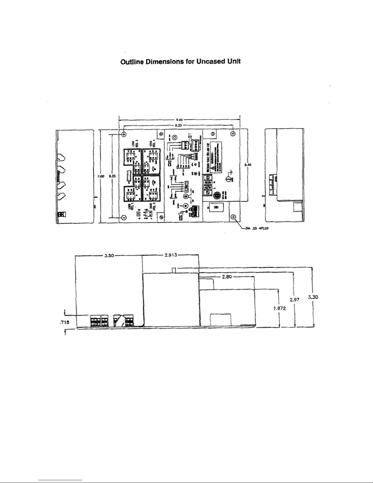
entering the enclosure. Outline dimensions for the
standard DXp¬10/15 transmitter are presented in
Figure 2-1.
2.2.2 Explosion-Proof and Division 2
Options.
DXp units may be ordered with an optional
explosion-proof enclosure for use in Division I
hazardous locations. Dimensions for the optional
explosion-proof enclosure are provided in
Appendix C.
For Division 2 applications, FM approved units are
available as non-incendive devices in NEMA 4/4X
enclosures with dimensions identical to those
presented in Figure 2-1.
Figure 2-1. DXp-10 Outline Dimensions
2-1
Page 10

Figure 2-2. Load Cell Connections.
2.3 ELECTRICAL
2.3.1 Transducer Inputs.
Up to four load cells can be connected to the
summing circuit within the DXp. Connect individual
load cells directly to the circuit board connectors
as shown in Figure 2-2. Excitation and signal
connection locations are dearly marked according
to function and standard color code.
If more than four cells are required, an external
308A summing junction box must be used. Make
all load cell connections in the 3084 unit, not the
DXp-10/15. Connect the output leads of the 3084
summing box to the load cell #1 terminal blocks in
the DXp. Sense leads from the 3084 must be
connected to the sense terminal blocks in the
DXp-10/15 (Figure 2-2). Jumpers JF1 and JP2
must be removed.
2.3.2 Serial Communication.
If a deadweight or substitution method of
calibration is being used, the load cal cable can be
shortened as required. The leads should be retinned before the final connection is made.
NOTE: If tension or universal load cells are used,
red (-signal) and white (+ signal) leads may need
to be reversed.
A terminal connector is provided for RS 485 wire
connections (Figure 2-3). Multiple DXp
transmitters, networked together, are wired in a
parallel configuration with a termination jumper
installed on the last instrument. A pair of twisted
wires (14-20 gauge) is all that is required for
interconnection. Communication lines should not
be run near ac voltage power lines.
Figure 2-4. Ac Power Connections and Fuse
2-2
Page 11

2.3.3 Analog Output.
When the analog option is installed (shown,
Figure 2-3), a three position terminal connector
is provided for 4-20 mA, 0-10 V, and common
connections. As with serial communication, the
wiring should be routed away from ac power
lines and other sources of EMI. The current
output is essentially immune to noise and can be
transmitted long distances. The voltage output is
susceptible to EMI/RFI and should be used only
for short distances.
2.3.4 Mains (AC) Power (Figure 2-4).
A screw terminal is provided for permanent
transmitter power connection. DXp transmitters
can be switch selected to operate at 115 or 220
VAC (see SW1, Figure 2-4). Before connecting
power to the unit, verify that the proper power
selection has been made. The two position
terminal block is equipped with a clear plastic
cover to prevent operator injury. Cable can be
either solid or stranded 12 or 14 gage with a
ground conductor.
The transmitter is protected with a 114 amp slow
blow fuse, located adjacent to the mains
terminal block. If the fuse opens, replace it with
the same type and current rating.
2.3.5 Auxiliary I/O Port.
The auxiliary I/0 port connection is a factory test
port and is not useful to an operator.
2-3
Page 12
SECTION 3. Configuration
3.1 GENERAL
Set-up and calibration of the DXp-10/15 is
accomplished by an operator without
programming using the DIP switches, pushbuttons, and toggle switches within the unit.
Units connected to an LCp-40 or computer terminal can be set-up and calibrated remotely via
the serial port (see Appendix E).
3.2 SET-UP
3.2.2 Excitation Voltage.
All units are shipped from the factory set for 10
volt excitation.
3.2.3 Serial Format, Address, and
Baud Rate.
DIP switch selections for transmitter address,
baud rate and serial interface format are
presented and defined in SECTION IV, Serial
Communication.
3.2.1 Power Selection
All units are shipped from the factory configured
for 115 VAC operation. To change the voltage
selection to 230 VAC, change SW1 (see Figure
2-4) to the 230V setting. The unit will operate
within specification at 50 or 60 Hz.
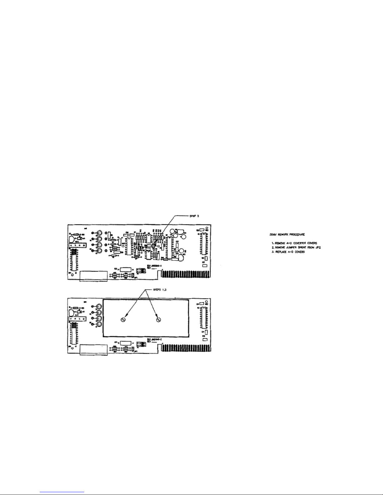
3.2.4 Input Range Selection.
Units are shipped configured for a 25 mV input
range. To increase this range to 35 my, remove
the jumper shunt from JP2 on the A-D converter
board as shown in Figure 3-1 (see Appendix A
photo for A-D board location).
Figure 3-1. 35 mV Input Conversion Instructions
3.3 CALIBRATION
Note: All switches mentioned in paragraphs
3.3.1 – 3.3.4 are depicted in Figure 3-1.
3.3.1 Digital Calibration.
The transmit only serial output can be digitally
calibrated using the DIGITAL selector, 1NC/DEC
and ENTER switches mounted on the DXp10/L5 control panel. For those systems where
applying a full capacity dead weight or input
signal is not practical, the DXp-10/15 will
automatically calculate a linear full span
calibration based on a single span point. See
Table 3-1 for instructions.
3-1
Page 13
3.3.2 Analog Calibration.
The analog output is calibrated independently of
the digital calibration and can be set using span
points anywhere between zero and full scale
capacity. The 0-10 V and 4-20 mA outputs CAN
NOT be calibrated independently. See Table 3-2
for complete analog calibration instructions.
3.3.3 Monitor Mode Calibration.
The terminal/computer interface option enables
the DXp-101L5 to be calibrated remotely from a
host computer or terminal. The monitor mode
functionally accesses the software routines used
to provide remote access via the keypad of an
LCp-40 Network Controller. In response, the
DXp-10/15 transmits two lines of information
similar to the two line display on an LCp-40. In
this mode the capacity, graduations, decimal
point, 5 point linearization and other values can
be established from the host device. Help
messages also can be accessed at any time to
aid in the set-up process. The procedure
recorded in Table 3-3 shows the command
sequence required to perform remote
calibration. Consult SECTION IV for serial
communication details.
3.3.4 LCp-40 Calibration.
When networked to an LCp-40, 41, or 42
controller, the DXp-10/15 can be remotely
calibrated using the controller display and
keypad. In this configuration, up to five
linearized span points can be entered. Appendix
E presents step by step flow diagrams for
remote LCp-40 calibration and parameter setup.
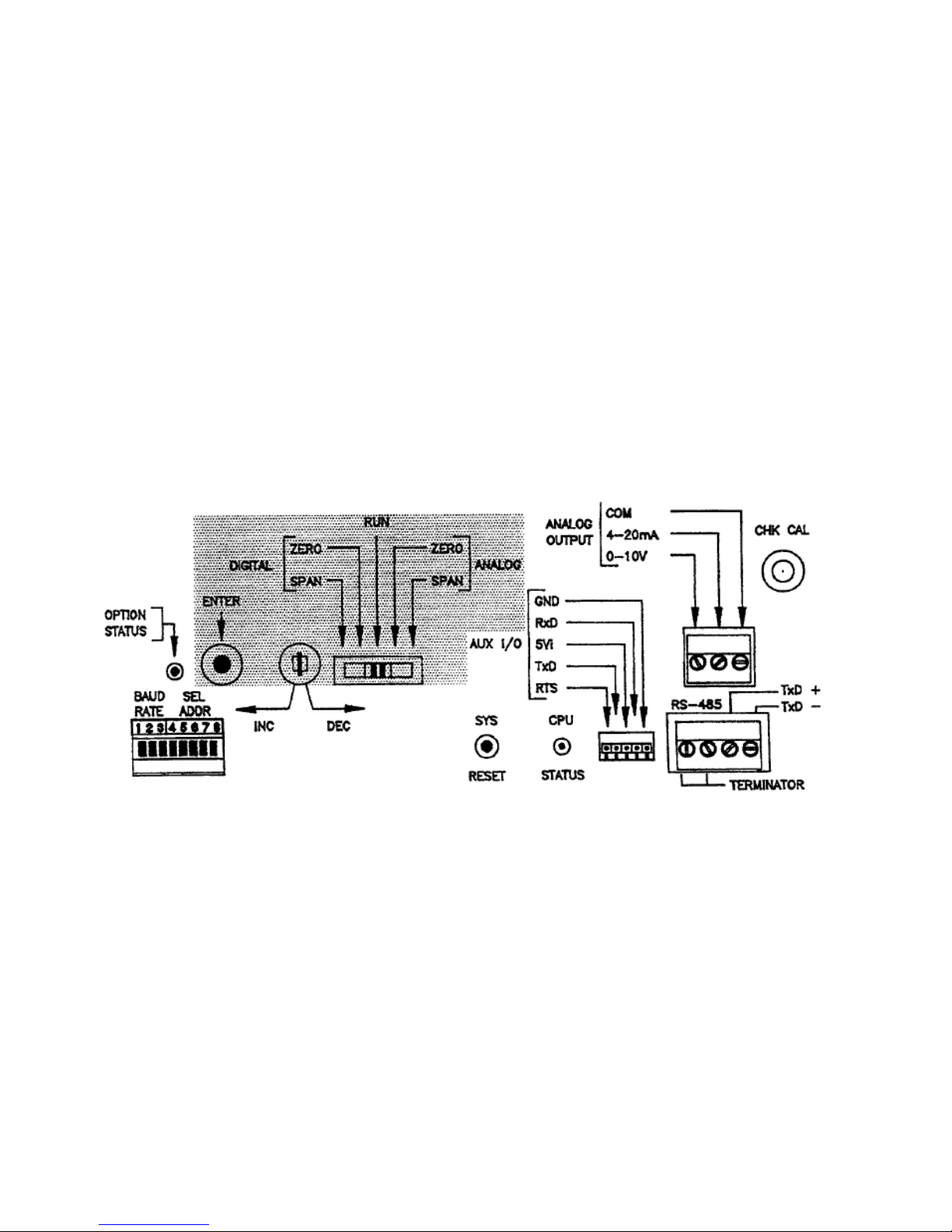
Figure 3-2. Set-up and Calibration Switch Locations (Shade)
Table 3-1. DXp-10 Digital Calibration
Instructions
[1]. Connect Load Cells and Remote
Terminal.
Install the load cells and wire them to the
DXp-10/15. Connect the RS 485 serial
output to a compatible terminal/readout
device. Select a compatible serial output
format and establish that the
communication link is operating (paragraph
3.2.3).
[2]. Establish Zero.
Make sure that all dead weight (vessel,
mixer, pipes, etc) is applied as it will be
during normal operation. Move the five
position slide switch (Figure 3-2) to the
digital zero position. Press the enter
button to acquire zero and wait
approximately 5 seconds for the zero
reference value to be stored. The red
OPTION STATUS LED will resume
flashing when the storage procedure is
complete.
3-2
Page 14

[3]. Load System.
Apply a known ―live‖ weight value to the
scale/vessel or input a known mV/V signal
from a BLH 625 calibrator to the DXp unit.
(NOTE: An external mV source cannot be
used to calibrate a DXp-10/15. A BLH 625
calibrator is required. If a 625 calibrator is
not available, contact a BLH field service
center for assistance.)
[4]. Establish Full Span.
Move the 5 position slide switch to the
digital span position. Use the
increment/decrement toggle switch to
increase or decrease the displayed
(terminal/output device) weight value until
the displayed value matches the known
weight value. Note that the rate of the
value change accelerates the longer the
switch is depressed. When the desired
value is displayed, press the enter button
and wait approximately five seconds for
storage. Again, the red OPTION STATUS
LED will resume flashing when storage is
complete. NOTE: There is no decimal
point available using this calibration
method. The DXp will default to the best
resolution possible based upon the scale
capacity and input signal.
[5]. Resume Normal Operation.
Return the 5 position slide switch to the run
position. Digital calibration is complete.
Table 3-2. DXp-10 Analog Calibration
Instructions
[1]. Connect Load Cells and Volt/Current Meter.
Install the load cells and wire them to the
DXp-10/15. Connect the analog output to a
voltage or current meter.
[2]. Establish Zero Reference/First Span Point.
Make sure that all dead weight (vessel,
mixer, pipes, etc.) is applied as it will be
during normal operation. Move the five
position slide switch (Figure 3-2) to the
analog zero position. Use the
increment/decrement toggle switch to
adjust the analog output so that the desired
value is displayed on the meter. Holding
the toggle switch in the depressed position
increases the rate of change. Press the
enter button to acquire zero and wait
approximately 5 seconds for the zero
reference value to be stored. The red
OPTION STATUES LED will resume
flashing when the storage procedure is
complete.
[3]. Load System.
Apply a known ―live‖ weight value to the
scale/vessel or input a known mV/V signal
from a BLH 625 calibrator to the DXp unit.
(NOTE: An external mV source cannot be
used to calibrate a DXp-10/15. A BLH 625
calibrator is required. If a 625 calibrator is
not available, contact a BLH field service
center for assistance.)
[4]. Establish Full Span.
Move the 5 position switch to the analog
span position. Use the
increment/decrement toggle switch to
increase or decrease the displayed (meter
display) weight value until the displayed
value matches the known weight value.
When the desired value is displays, press
the enter button and wait approximately 5
seconds for storage. Again, the red
OPTION STATUS LED will flash when
storage is complete.
[5]. Resume Normal Operation.
Return the 5 position slide switch to the run
position. Digital calibration is complete.
3-3
Page 15

Table 3-3A. Setup in Monitor Mode.
ASCII Command in
Order of Operation
Serial Output
Explanation
SMM
Set Monitor Mode
Access Monitor Mode
C
Setup
Access Setup to Enter/Alter System
Parameters
M
5000 – CAP LB
Modify Setup
M-I or D
500.00 (flashing)
CAP LB
Modify Capacity
I or D
400.00
Increment or Decrement Digits
E
400.00
CAP LB
Enter Capacity
E
400.00
Select Decimal Position
M-I or D
400.00
DECIMAL
Change Decimal Position
E
400.00
Enter Decimal
E
0.050
GRAD
Graduation Setting
M
I or D
E
0.050
0.050
0.050
GRAD
Modify Graduation
Increment/Decrement
Enter
E
102
OVER
Overrange Setting
M-I or D
OFF/102
Select OFF or 102%
E
20
ZERO
Change Zero Selection
M-I or D
2
ZERO
Select 2% or 20%
Full Scale Zero Allowance
E
2
ZERO
Enter Selection
E
OFF
MN BAND
Change Motion Band Selection
M-I or D
OFF
MN BAND
Select OFF, 1, or 2 counts
E
OFF
MN BAND
Enter Selection
E
SETUP
Parameter Enter/Alter Complete
E
Normal Weighing
3-4
Page 16

Table 3-3B. Calibration in Monitor Mode
ASCII Command in Order of
Operation
Serial Output
Explanation
E
CAL
Enter Calibration Mode
M
000
ZERO
Zero Setting
Z
000
Acquire
Acquire Zero
E
CLEAR
Clear Old Span Point(s)
M-Z or E
SPANS
Span Setting
M
5100.00
166329
Span 1 Value
Internal Counts
X
SPANS
Skips Span
E
Adjust
Change Spans
M
000 (flashing)
SPAN 1
Adjust Span1
M
0000 (flashing)
Acquire Span 1
M & I/D
1000.0
Enter Span 1 Weight Value
Note: Use M & E to access and
change spans 2-5 if desired.
E E
Normal Weighing
Exit CAL Mode
3.4 CHECK CAL
The standard transmitter is provided with a check
cal feature that can be operated manually by
pushing a button on the DXp operator panel (see
Figure 3-1) or remotely via the serial port. This
feature provides a check of the instrument
calibration to verify that drift or other problems
have not occurred. Check cal uses an internal
shunt resistor circuit to provide a fixed repeatable
signal into the input of the transmitter. The input
signal produces a known output which can be
verified by viewing the terminal/meter used to
perform calibration.
Due to the infinite variety of calibrations and
applications, a range of shunt calibration values
are available by changing the position of the
resistor circuit component carrier in socket U6 on
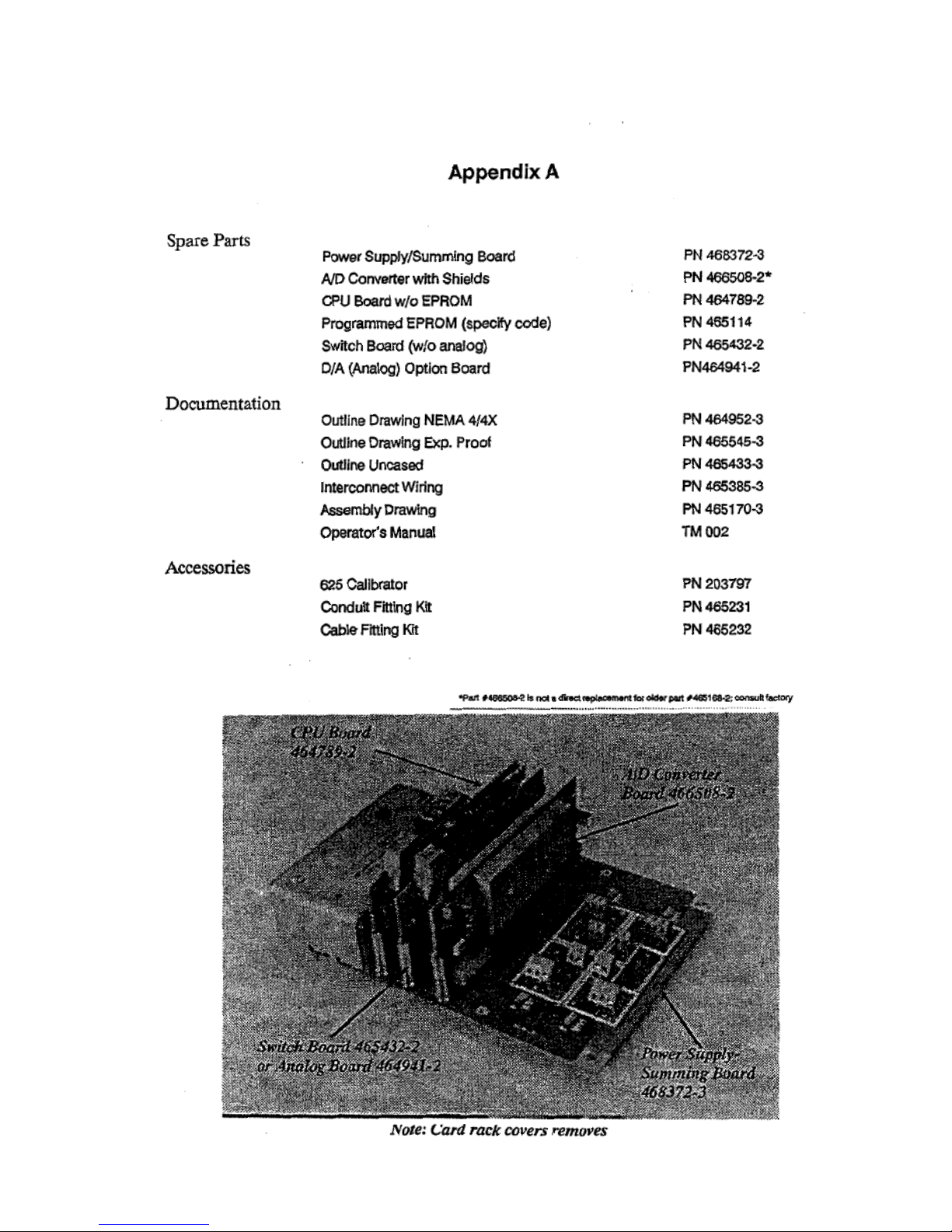
the A/D board. Access is obtained by removing the
card rack cover and should be performed by a
qualified technician. In most cases, a value that
produces a signal equal to 80% of system capacity
is desired. Table 3-4 lists the positions and
resulting percent of output given a typical 2.0 mV/V
load cell application.
3-5
Page 17

Table 3-4. Check Cal Percentage Selection/Module Position.
Module
Position
Resistance
(ohms)
1 Cell
2 Cells
3 Cells
4 Cells
1
13400
125%
114%
78%
59% 2 94800
125%
125%
110%
84% 3 15800
125%
97%
66%
50% 4 70400
41%
22%
15%
11% 5 546000
53%
28%
19%
14% 6 395000
74%
39%
26%
20% 7 309000
94%
50%
33%
25% 8 237000
125%
65%
44%
33%
Setting
(Flashes)
Conversions
Averaged
1 1 2 2 3 4 4 8 5
16 6 32 7 64 8 128
Percent of Full Scale (2 mV/V) Output when Check Cal Button is Pressed.
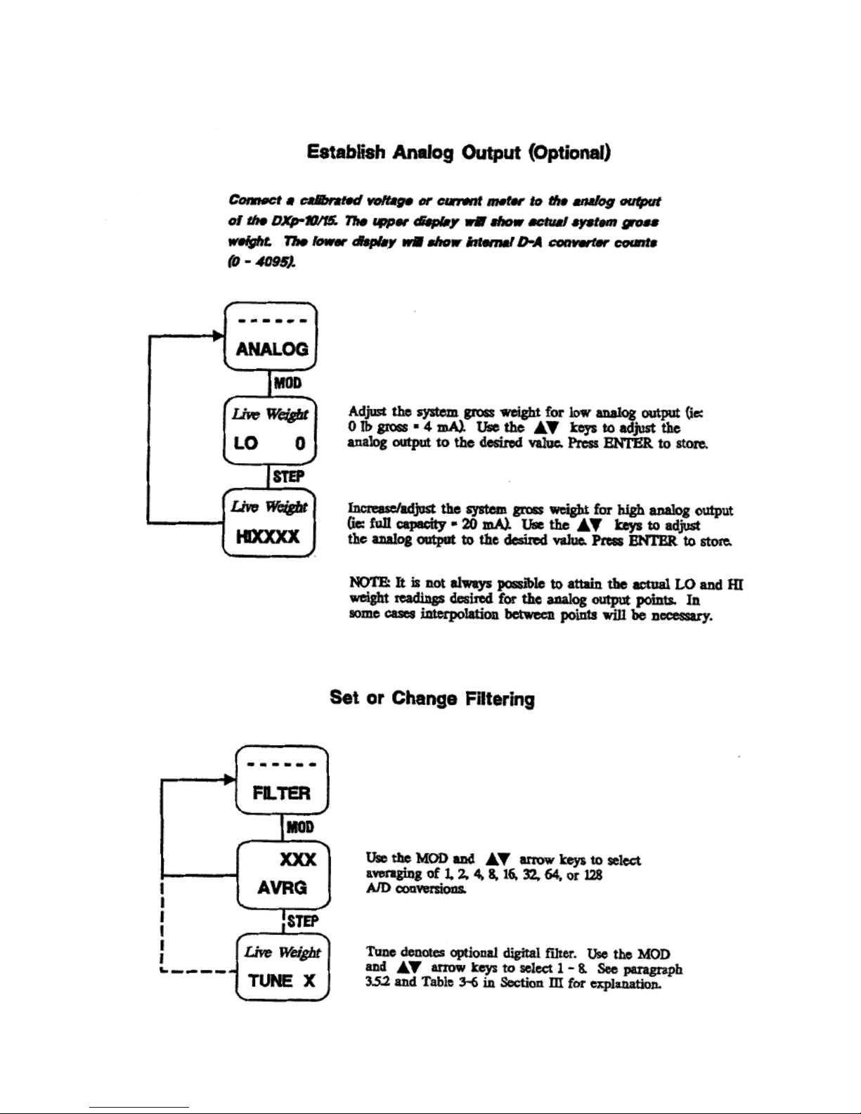
3.5 FILTER SELECTION
3.5.1 Standard Filter.
Standard filtering offers simple successive
averaging of A-D conversions to stabilize the
output signal. Pressing and holding the enter
button accesses the selection mode: the
increment/decrement toggle switch changes the
setting. As the setting is changed, the OPTION
STATUS LED flashes to indicate the selection.
Average selections of 1, 2, 4, 8, 16, 32, 64 or 128
are available (Table 3-5).
Table 3-5. Standard Filter Selections
Hold down enter key and toggle INC/DEC key for
selections.
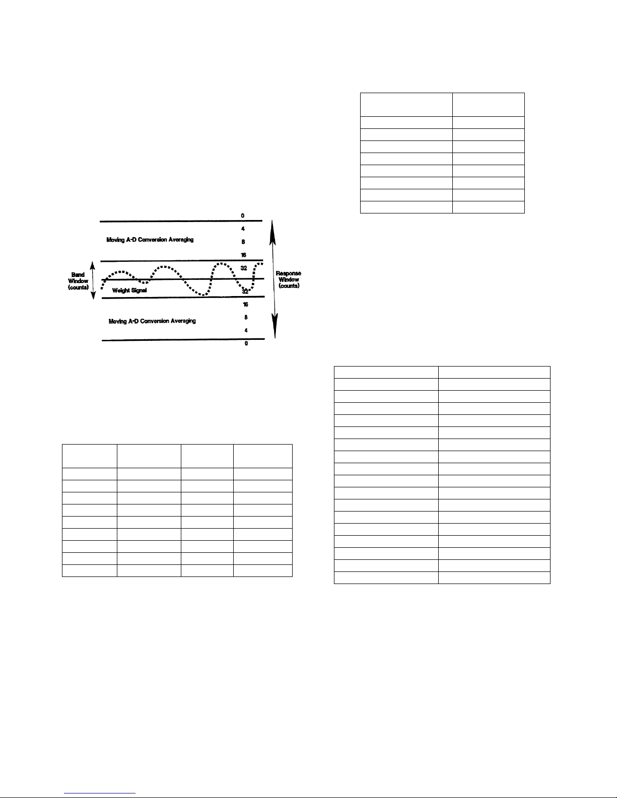
3.5.2 Optional Digital Filtering.
Optional digital filtering offers the benefits of
successive averaging without the corresponding
delay in response time to real weight changes.
Digital filtering software determines the number of
A-I) conversions to be averaged on a moving basis
(Figure 3-3). Conventional averaging takes place
at the selected rate within a window of counts
defined as 'band (Table 3-6). If the signal exceeds
the band count limits, averaging continues on a
reduced basis within the larger window of counts
designated 'response'. Once the signal exceeds
both windows, band and response, averaging
stops until the signal begins to stabilize again. This
two-dimensional approach provides fast, accurate,
and stable weight data for difficult process
weighing applications. Consult BLH technical note
7D-071' for a complete explanation of optional
digital filtering.
Pressing and holding the ENTER button accesses
the filter selection mode: the increment/decrement
toggle switch changes the setting. As the setting is
changed, the OPTION STATUS LED flashes to
indicate the selection (one flash = setting one,
etc.). Table 3-6 (upper portion) defines the
parameters of each of the eight possible
selections. Releasing the ENTER button stores the
3-6
Page 18
10.75 11 26
CD
8
•
OLII
111.14111091C9. SIC.
OUTLINE
1
selection. After selecting a filtering parameter,
Setting
(Flashes)
Averaging*
Band
(Counts)
Response
(Counts)
0 * 0 0 1 * 1 4 2 * 2 8 3 * 4
16 4 * 8 32 5 D* 1 4 6 D* 2 8 7 D* 4 16 8 D* 8 32
Setting (Flashes)
Conversions
Averaged
1 1 2 2 3 4 4 8 5
16 6 32 7 64 8 128
DXp Parameter
Default Specification
Capacity
10,000
Units
Pounds
Decimal Point
None
Grad
1
Overrange
Off
Zero Band
2% of capacity
Motion Band
Off
External Zero
0
Span 1 Units
10,000
Span 2 Units
Cleared
Span 3 Units
Cleared
Span 4 Units
Cleared
Span 5 Units
Cleared
D/A Zero Volt Output
0 (min bit of 4095)
D/A 10V Output
4095 (max bit of 4095)
Filter
1
Averaging
1
choose an averaging value (Table 3-6 lower
portion). Select averaging by holding the toggle
switch to increment or decrement to access the
selection mode. Press the ENTER button to
change. The OPTION STATUS LED flashes to
indicate the selection number (14 flashes).
Releasing the toggle switch stores the selection.
Figure 3-3. Optional Digital Filtering Operation.
Table 3-6. Optional Digital Filtering Selections.
*Insert averaging value as selected in table
above; ‘D’ doubles averaging value selection.
3.6 Factory Default Calibration
Table 3-7 presents the DXp-10/1.5 factory
calibration default parameters. All DXp units
shipped by BLH are calibrated to the specifications
shown in Table 3-7.
Table 3-7. Factory Calibration Default
Parameters
Filter Type Selection: Hold down enter key and
toggle INC/DEC key for selections.
Averaging Selection: Hold toggle switch to
INC/DEC, press enter key for selections.
* The Dxp-10 has up to 368,640 raw internal
counts.
3-7
Page 19

SECTION 4. Serial Communication
Switch
Positions
1 2 3
Baud
Rate
Interface
0 0 0
9600
Digi-System Network
1 0 0
28800
Digi-System Network
0 1 0
57600
Digi-System Network
1 1 0
1200
Continuous Output
0 0 1
9600
Continuous Output
1 0 1
1200
Terminal Interface
0 1 1
9600
Terminal Interface
1 1 1
-
Reserved Setting; used
for special protocol
interface options
Switch
Position
4 5 6 7
Address
0 0 0 0
16
1 0 0 0
1
0 1 0 0
2
1 1 0 0
3
0 0 1 0
4
1 0 1 0
5
0 1 1 0
6
1 1 1 0
7
0 0 0 1
8
1 0 0 1
9
0 1 0 1
10
1 1 0 1
11
0 0 1 1
12
1 0 1 1
13
0 1 1 1
14
1 1 1 1
15
4.1 GENERAL
The DXp-10/15 is equipped with a variety of
standard and optional serial output formats that
are selected using a series of DIP switches
(Figure 4-1). DIP switch positions 1, 2, and 3
allow three format choices; Digi-System
network, continuous output, and
terminal/computer interface (Table 4-1). All three
types of DXp interfacing will be discussed in the
following paragraphs. Positions 4-7 designate
transmitter address for applications requiring
more than one DXp unit (Table 4-2). Switch
position 8 is unused and should be left in the '0'
(ON) position.
NOTE: If the MODBUS option is installed and
enabled, use the DIP switch selections
presented in Figure 4-2• (Page 4-4).
interface is much greater than simple analog
current or voltage approximates. Simplex
outputs are transmitted in the format on page 42, top left-hand column.
Table 4.1. Serial Interface and Band Rate
Selections
4.1.1 LCp-40 Digi System Network.
Up to 16 DXp-10/1.5 transmitters can be
networked to the LCp-40 Network Controller.
The half duplex format used to run the network
is designed to provide remote operation of
gross, net, tare, zero, calibration/set-up, and
diagnostics, at high speed. This format is not
intended for direct interface with a terminal or
computer. The baud rate is selectable to
accommodate systems with very long (low baud)
or short (high baud) distances between DXp
units.
4.1.2 Standard Simplex Output
(Continuous Output).
The simplex output format is designed to
transmit gross weight data (ASCII coded) to a
remote terminal or computer. The accuracy of
this point to point, digital communication
4-1
Page 20

Figure 4-1. Serial Communication Parameter Selection Switch.
ASCII
Command
Description
Action
Response
W
Weight
Return Current Weight
Data and Mode
Information
[stx/adr/pol/data/sp/units/mode/stat/tc/CRLF]
G
GROSS
Switch to Gross Mode
[stx/adr/pol/data/sp/units/‖G‖/stat/tc/CRLF]
N
Net
Switch to Net Mode
[stx/adr/pol/data/sp/units/‖N‖/stat/tc/CRLF]
T
Tare
Switch to gross mode and
Tare
[stx/adr/pol/data/sp/units/‖N‖/stat/tc/CRLF]
Z
Zero
Switch to gross mode and
Zero
[stx/adr/pol/data/sp/units/‖G‖/stat/tc/CRLF]
L
Pounds
Switch to Pounds
[stx/adr/pol/data/sp/‖L‖/mode/stat/tc/CRLF]
K
Kilograms
Switch to Kilograms
[stx/adr/pol/data/sp/‖K‖/mode/stat/tc/CRLF]
SMC
Set Continuous
Mode
Send weight data
continuously
[stx/adr/pol/data/sp/units/mode/stat/tc/CRLF]
SMD
Set Demand
Mode
Must request data
SC
Check Cal
Remotely Operates Check
Cal
[stx/adr/pol/data/‖C‖ ―C‖/stat/tc/CRLF]
4.1.3 Computer/Terminal Interface
(Optional).
This half duplex (transmit and receive) format is
designed for two way communication between a
single D4-10/15, or a network of DXp-10/15 units,
and a computer/terminal. Protocol accommodates
all operations such as gross, net, tare, zero, as
well as remote set-up, calibration, and filter
selection. Use of this format requires customer
developed device specific software to run the
various network operations. Table 4-3 defines the
terminal interface protocol. Monitor mode (see
Table 4-3) allows many of the LCp¬40 keypad
switch functions to be implemented from the host
terminal/computer. These functions are essential
when performing remote calibration and parameter
set-up.
Table 4-3a. Computer/Terminal Interface Protocol.
4-2
Page 21

Table 4-3b. Computer/Terminal Interface Protocol.
ASCII
Command
Description
Action
Response
SMM
Set Monitor Mode
Transmit display each update
Instrument display output
Lower Display/sp/Upper
Display/CR
SMR
Set Mode for Remote
Inhibit
Of Temperature
Conversions
Turn off Auto Temperature
Compensation Cycles
SMA
Set Mode for Automatic
Temperature
Compensation
Turns on Temperature
Compensation Cycles (note 1)
SFx
Set Digital Filter Value
X = 0-8
Remote Selection of Digital
Filter Value (note 2)
SVx
Set Digital Averaging
Value
x = 0-7
Remote Selection of
Digital Averaging (note 2)
I
Increment
Increment blinking digit/selection
Monitor Mode Only
D
Decrement
Decrement blinking digit/selection
Monitor Mode Only
U
Units
Select lb/kg when modifying
capacity
Monitor Mode Only
M
Modify/Shift
Same as MOD key
Monitor Mode Only
E
Enter/Step
Same as Enter/Step key
Monitor Mode Only
H
Help
Same as Help key
Monitor Mode Only
X
Exit
Same as Exit key
Monitor Mode Only
C
Cal
Same as Cal key
Monitor Mode Only
AXX
Address 01 – 16
Enable Addressed DXp Unit
Note 1: In auto mode, 90 millisecond temperature compensation cycles occur once every 2 seconds.
Temperature cycles are inhibited if there is critical positive or negative system motion.
Note 2: Remote filter and averaging selections are not stored in EEPROM. EEPROM values will be
loaded at time of unit power up. See Table 3-6 for selection definitions.
List of abbreviations.
stx= 1char. Start of Text (02H)
adr= unit address 01-16,3 chars; high add, low add, Sp
POI = Polarity sign; space (ASCII 2H) for positive data, minus (-) (ASCII 2D) for
negative data
data= 7 char; six digits with decimal point or leading space, leading zeros = spaces
sP = 1 char; ASCII space (20H)
units= 1 that; L= pounds, K= kilograms, C= Checkcal
mode= 1 char; G= gross, N= net, C= checkcal
Z= zero cal, and S= span cal
stat = 1char; M (motion), 0 (overload), Or sp
to = 1 char, temperature compensation; IR= remote
inhibit sp = auto
CR/LF= 2 char; carriage return, line feed (ODH/OAH)
"= single quotes = ASCII character or string
upper display = 7 ASCII characters
lower display = 6 ASCII characters
4-3
Page 22

4.1.4 MODBUS BTU Protocol
(Optional).
MODBUS is a protocol developed by Modicon
Inc. for communication between programmable
controllers and operator stations which support
them. For a complete description of the
MODBUS interface, request BLH technical
document TD-075. If the MODBUS option is
installed and enabled (DIP switch position 8 =
OFF), interface parameters must be selected
using the DIP switch configurations shown in
Figure 4-2
If the MODBUS option is installed but not
enabled, DIP switch selections will function as
shown in Tables 4-1 and 4-2 (page 4-1).
MODBUS protocol formats are presented on the
following pages.
Figure 4-2. DIP Switch Selections for MODBUS Protocol.
MODBUS FUNCTIONS SUPPORTED:
02 Read Input Status
03 Read Holding Registers
06 Preset Single Register
16 (10 Hex) Preset Multiple Registers
DATA FORMATS:
FORMAT #1: One 16 bit signed integer -
32768 to 32767 for all data
FORMAT #2: Two 16 bit signed integers
for weight data (the two integers must
be added together to get -65536 to
65534) One 16 bit unsigned integer for
status & setup parameters
FORMAT #3: Two 16 bit signed Integers
for weight data (the high word, 1st
integer, must be multiplied by 32768.0
then added to the low word, 2nd Integer)
One 16 bit unsigned integer for status &
setup parameters
4-4
Page 23

INPUT STATUS DEFINITIONS (Function 02)
INPUT STATUS
1 MOTION
2 UNABLE TO TARE/ZERO
BECAUSE OF MOTION
3 UNABLE TO ZERO BECAUSE
OF UMIT
4 CHECK CAL
5 ND UNDERLOAD
6 A/D OVERLOAD
7 SPARE (0)
9 IN ANALOG CAL
10 IN DIGITAL CAL
11 ACQUIRING CAL DATA
12 FILTER BEING CHANGED
13 EEPROM CODE ERROR DEFAULT DATA LOADED
14 EEPROM READ ERROR
15 EEPROM WRITE ERROR
16 EEPROM DATA ERROR FAULTED DATA REPLACED WITH
DEFAULT DATA
8 POWERUP
DXP10/15 READ ONLY REGISTERS (Function 03)
READ ONLY FORMAT #1 FORMAT #2 FORMAT #3
ADR #REG ADR #REG ADR #REG
STATUS 40001 1 40033 1 40065 1
GROSS 40002 1 40034 2 40066 2
NET 40003 1 40036 2 40068 2
DXP10/15 READ/WRITE REGISTERS (Functions 03, 06-format #1 only, 16)
READ/WRITE FORMAT #1 FORMAT #2 FORMAT #3
ADR #REG ADR #REG ADR #REG
TARE 40004 1 40038 2 40070 2
ZERO 40005 1 40040 2 40072 2
ZERO UMIT 40006 1 40042 1 40074 1
FILTER TUNE 40007 1 40043 1 40075 1
AVERAGING 40008 1 40044 1 40076 1
MOTION 40009 1 40045 1 40077 1
MOTION TIMER40010 1 40046 1 40078 1
SPAN CAL 40011 1 40047 2 40079 2
DXP10/15 WRITE ONLY COMMAND REGISTER (Functions 06, 16)
WRITE ONLY FORMAT #1
ADR #REG COMMANDS
01 = TARE net weight
COMMAND 40101 1 02= ZERO gross weight
STATUS REGISTER BIT DEFINITIONS for addresses 40001, 40033, 40065
BIT STATUS
0 MOTION
1 UNABLE TO TARE/ZERO BECAUSE OF MOTION
2 UNABLE TO ZERO BECAUSE OF LIMIT
3 CHECK CAL
4 ND UNDERLOAD
5 ND OVERLOAD
6 SPARE (0)
7 POVVERUP
4-5
Page 24

8 IN ANALOG CAL
9 IN DIGITAL CAL
10 ACQUIRING CAL DATA
11 FILTER BEING CHANGED
12 EEPROM CODE ERROR - DEFAULT DATA LOADED
13 EEPROM READ ERROR
14 EEPROM WRITE ERROR
15 EEPROM DATA ERROR - FAULTED DATA REPLACED WITH DEFAULT DATA
ZERO LIMIT, FILTER, & MOTION SETIINGS
ZERO LIMIT (note on next page)
Setting % of capacity
0 2
2 20
FILTER TUNE AVERAGING
setting band Response setting averaging
(counts) (counts)
0 OFF OFF
1 1 4 0 1
2 2 8 1 2
3 4 16 2 4
4 8 32 3 8
5* 1 4 4 16
6* 2 8 5 32
7* 4 16 6 64
8* 8 32 7 128
*tune settings 5-8 double current averaging setting
MOTION MOTION TIMER
setting counts setting time
0 OFF 0 0.8 sec
1 1 1 1.6 sec
2 2 2 32 sec
3 3 3 6.4 sec
If the count difference from conversion to conversion is greater than the motion setting, the motion status
bit is set to 1. Once the count difference from conversion to conversion returns to be equal to or less than
the motion setting, the motion bit remains set for the time selected for the Motion Timer.
Note 1: Zero limit settings are stored in EEPROM and are not lost if unit powers down. Filter and motion
settings are lost if unit powers down.
Note 2: counts refers to weight graduations. If weight graduations are 2 lb increments then presetting a
register to 2 would mean 4 lbs.
4-6
Page 25

4.1.5 Fisher ProVox Protocol
(Optional)
DXp-15 transmitters may be ordered with the
Fisher ProVox protocol. Units equipped with this
option communicate with a Fisher ProVox
C16921 external interface card, configured for
the 'Toledo' interface. For a further description of
the hardware and software aspects of this
interface, refer to BLH technical document TD-
073.
Definitions for the byte and bit formats
transmitted by the DXp-15 are presented below.
To select the ProVox protocol option, DIP switch
positions 1-3 must be set to 14,1. Baud rate is
fixed at 4800 continuous output.
NOTE: Hardware requirement - An external
hardware converter is required to change the
DXp-15 RS-485 output to 20 mA current loop for
interface with the ProVox CL6921 card.
FISHER PROVOX INTERFACE
1. TRANSMTT ONLY FORMAT - approx.
every 200ms
2. BYTE FORMAT -10 BIT ASCII: 1 start,
7 data, 1 parity - even, 1 stop
3. DATA OUTPUT FORMAT GROSS/TARE or NET/TARE provided (tare always =0)
4. TOTAL (RESPONSE PACKET)
FORMAT -18 bytes - 4800 baud –
continuous
4-7
Page 26

4.1.6 Allen-Bradley Remote I/O
(Optional).
DXp-15 transmitters are available with the AllenBradley Remote 110 interface option. This
option is available via a technology licensing
agreement between BLH and Allen-Bradley.
Functionally, this interface allows up to 8 BLH
DXp-15 transmitters to communicate with an AB
PLC-5 or SLC-5 programmable logic controller
using discrete data transfers. Consult BLH
manual TM010 for complete details.
4-8
Page 27

SECTION 5. Operation
Error Message
Description
Action
E02
Signal Overrange
Check for open load cell circuit or overranged
load cell (reading in excess of 35 mV at J-Box
E03
Signal Underrange
E04
Digital Overrange
Return to setup and increase capacity
E10
Internal Autozero Measure
Is out of range
If external summing, check that SEN+ and
SEN- leads are secure
E200
Cannot Attain Capacity
Return to setup and decrease capacity or
review hardware gain setting
E201
Cannot Attain Capacity
Return to setup and increase GRAD or review
hardware gain setting.
5.1 GENERAL
As a stand-alone unit (no terminal, computer, or
LCp-40), either analog or digital, the DXp-1W15
typically transmits only gross weight data upon
power-up. If the DXp-10/15 is being operated
remotely from a host terminal, computer, or LCp40, it can perform gross, net, tare, and zero
functions.
5.2 GROSS WEIGHT WEIGHING
In the gross mode, all of the live weight of the
system is transmitted. Live weight does not
include the dead weight of a vessel or other
mechanical equipment that is zeroed out during
calibration.
5.3 ZERO OPERATION
A new zero can be acquired to compensate for
changes in the dead load of the system due to
heel build-up etc. Acquiring a new zero
reference value does not affect the slope of the
calibration. The zero function in the DXp¬10/15
can be configured for either a 2% or a 20%
ceiling (max percent of full scale capacity) if the
unit is connected to a host terminal/computer or
LCp-40.
5.4 NET WEIGHT WEIGHING
Net weight weighing is used when the operator
wants to reset to zero to compensate for the
Table 5-1. Error Codes and Flashing Display Explanations
addition of live weight, or a container, before
adding a specific amount of material. Tare is
used to establish a zero reference in net mode.
5.5 TARE OPERATION
With the DXp-10/15 in net weighing mode, the
tare operation resets the output to zero. Taring
allows the operator to achieve a new zero
reference before addition of each ingredient so
that errors do not become cumulative.
5.6 ERROR DETECTION
When the DXp is reporting weight data to a host
computer, dashes will be transmitted if an
overrange condition occurs. When connected to
an LCp-40, the node identification and dashes
will be transmitted and displayed. When used in
the monitor mode, a complete library of error
codes is available for transmission (see Table 5-
1).
5.7 CHECK CAL OPERATION
Manually depressing or remotely activating
check cal through the serial port causes the
transmitted weight data to increase by the given
percentage (see Table 34). In systems using a
host computer, this check can be made on a
routine basis to verify the accuracy of the
system.
DXp-10/15 Error Messages (As seen on an LCP-40 display or computer/terminal in monitor mode)
5-1
Page 28

DXp-10/15 Power-Up/EEPROM Errors
LCp-40 Display
DXp-10/15 CPU
Status LED
Description
Action
―EE DFAULT‖
1 Blink
Default data loaded into
EEPROM (New EEPROM)
Press Reset on DXp-10/15
Press exit on LCp-40
―EE WRITE‖
2 Blinks
EEPROM write error
Press Reset on DXp-10/15
Press exit on LCp-40
―EE READ‖
3 Blinks
EEPROM read error
Press Reset on DXp-10/15
Press exit on LCp-40
―EE XXXXXX‖
4 Blinks
EEPROM checksum error
Press Reset on DXp-10/15
Press exit on LCp-40
Operating Mode
Key Pressed
Flashing Display
Explanation
Gross
TARE
LB/KG
Cannot tare gross weight
Gross
ZERO
LB/KG
Current weight out of zero range
Gross
DISPLAY
No Change
Display set to show gross only
Net
ZERO
LB/KG
Cannot acquire zero while in net mode
Net
TARE
MOTION
Cannot tare while in motion
Net
TARE
GROSS
Cannot tare negative gross weight
Net
TARE
LB/KG
Cannot tare, gross weight beyond capacity
NOTE: If pressing reset on the DXp does not clear an ―EE‖ error, consult factory.
Flashing Display Explanations (As seen on LCp-40 display or computer terminal)
5-2
Page 29
1
Page 30
2
Page 31
3
Page 32

Appendix C: Wiring and Outline Drawings
Customer Wiring Diagram
Standard Unit Outline
Explosion-Proof Enclosure Outline
4
Page 33

5
Page 34

6
Page 35

7
Page 36

8
Page 37

Appendix E
Remote Calibration Using an LCp-40, 41, or 42
DXp-10/15 transmitters can be calibrated and configured remotely using an LCp-40
series network controller. Remote calibration/configuration provides the advantage of
displaying parameter entries for maximum setup accuracy. The following pages present
flow diagrams for each available remote parameter entry.
9
Page 38

10
Page 39

11
Page 40

12
Page 41
13
Page 42

BLH
3 Edgewater Drive,
Norwood, MA 02062 U.S.A.
Phone (781) 298-2200
Fax (781) 762-3988
www.vishaypg.com
 Loading...