

1N1...A, 1N36..A Series
Vishay High Power Products
Medium Power
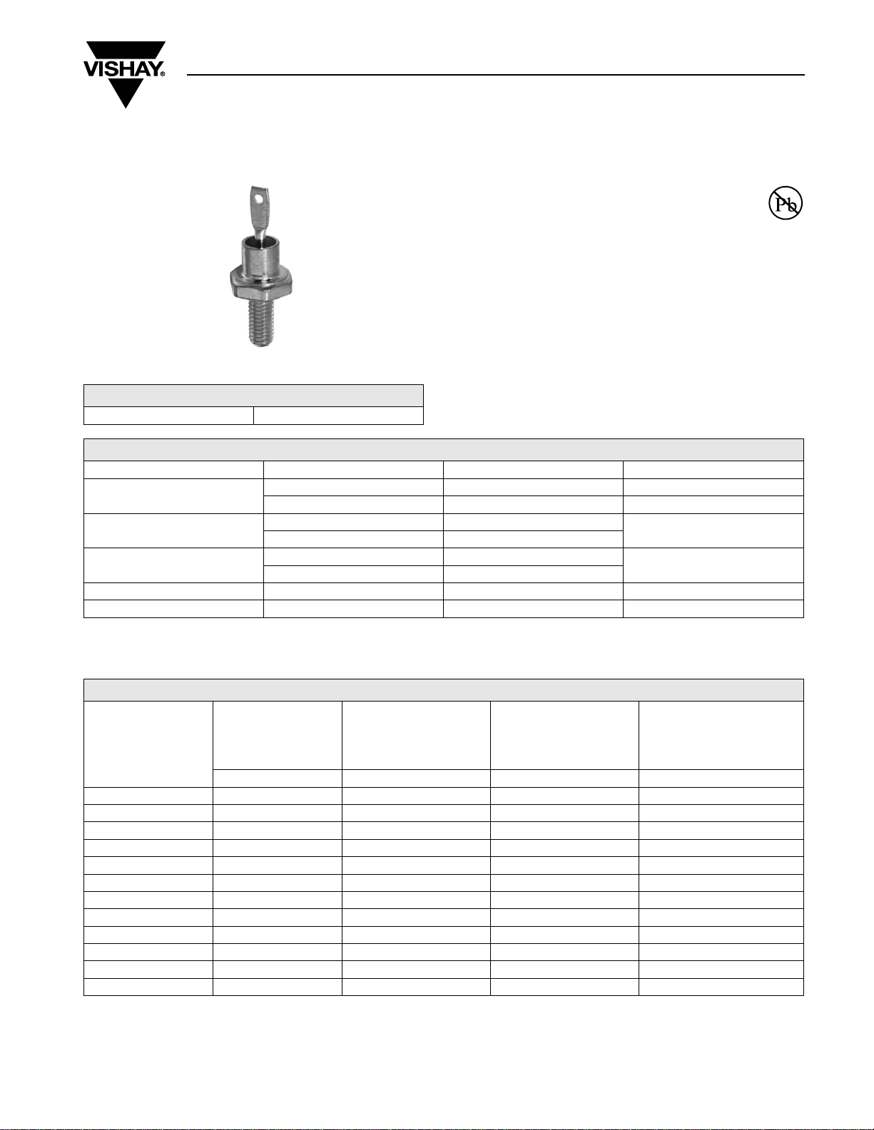
Silicon Rectifier Diodes, 12 A
FEATURES
• Voltage ratings from 50 to 1000 V
• High surge capability
• Low thermal impedance
• High temperature rating
• Can be supplied as JAN and JAN-TX devices in
accordance with MIL-S-19500/260
RoHS
COMPLIANT
DO-203AA (DO-4)
• RoHS compliant
PRODUCT SUMMARY
I
F(AV)
12 A
MAJOR RATINGS AND CHARACTERISTICS
PARAMETER TEST CONDITIONS VALUES UNITS
I
F(AV)
I
FSM
I2t
T
V
C
RRM
T
C
50 Hz 230
60 Hz 240
50 Hz 260
60 Hz 240
Range 50 to 1000
Note
(1)
JEDEC registered values
(1)
12
(1)
150
(1)
- 65 to 200 °C
(1)
ELECTRICAL SPECIFICATIONS
VOLTAGE RATINGS
V
, MAXIMUM
RRM
REPETITIVE PEAK
TYPE NUMBER
(2)
REVERSE VOLTAGE
V
= - 65 °C TO 200 °C TC = - 65 °C TO 200 °C TC = - 65 °C TO 200 °C TC = - 65 °C TO 200 °C
T
C
1N1199A 50
1N1200A 100
1N1201A 150
1N1202A 200
1N1203A 300
1N1204A 400
1N1205A 500
1N1206A 600
1N3670A 700
1N3671A 800
1N3672A 900
1N3673A 1000
(1)
(1)
(1)
(1)
(1)
(1)
(1)
(1)
(1)
(1)
(1)
(1)
V
, MAXIMUM RMS
R(RMS)
REVERSE VOLTAGE
V
(1)
35
(1)
70
(1)
105
(1)
140
(1)
210
(1)
280
(1)
350
(1)
420
490 900
560 1000
630 1100
700 1200
NON-REPETITIVE PEAK
Notes
(1)
JEDEC registered values
(2)
Basic part number indicates cathode to case; for anode to case, add “R” to part number, e.g., 1N1199RA
, MAXIMUM
V
RSM
REVERSE VOLTAGE
V
(1)
100
(1)
200
(1)
300
(1)
350
(1)
450
(1)
600
(1)
700
(1)
800
(1)
(1)
(1)
(1)
V
, MAXIMUM DIRECT
RM
REVERSE VOLTAGE
A
°C
A
A2s
V
V
50
100
150
200
300
400
500
600
700
800
900
1000
(1)
(1)
(1)
(1)
(1)
(1)
(1)
(1)
(1)
(1)
(1)
(1)
1N1...A, 1N36..A Series
Vishay High Power Products
Medium Power
Silicon Rectifier Diodes, 12 A
FORWARD CONDUCTION
PARAMETER SYMBOL TEST CONDITIONS VALUES UNITS
(1)
Maximum average forward current
at case temperature
I
F(AV)
180° sinusoidal conduction
Half cycle 50 Hz sine wave
or 6 ms rectangular pulse
Half cycle 60 Hz sine wave
Maximum peak one cycle
non-repetitive surge current
I
FSM
or 5 ms rectangular pulse
Half cycle 50 Hz sine wave
or 6 ms rectangular pulse
Half cycle 60 Hz sine wave
or 5 ms rectangular pulse
2
Maximum I
Maximum I
t for fusing
2
t for individual
device fusing
Maximum I
device fusing
2
√t for individual
I
Maximum forward voltage drop V
= 50
V
RRM
V
= 100 2.5
RRM
V
= 150 2.25
RRM
V
= 200 2.0
RRM
V
= 300 1.75
RRM
V
= 400 1.5
Maximum average
reverse current
RRM
V
= 500 1.25
RRM
V
= 600 1.0
RRM
V
= 700 0.9
RRM
V
= 800 0.8
RRM
V
= 900 0.7
RRM
V
= 1000 0.6
RRM
I
R(AV)
I
2
√t
t = 10 ms
t = 8.3 ms 240
2
t
t = 10 ms
t = 8.3 ms 340
(2)
t = 0.1 to 10 ms, V
I
FM
(3)
= 12 A (38 A peak), TC = 25 °C 1.35
F(AV)
Maximum rated I
Notes
(1)
JEDEC registered values
(2)I2
t for time tx = I2√t x √t
(3)
Maximum peak reverse current (IRM) under same conditions ≈ 2 x rated I
x
Following any rated load
condition and with rated
V
applied
RRM
Following any rated load
condition and with V
RRM
applied following surge = 0
With rated V
RRM
applied
following surge,
initial T
= 200 °C
J
With V
surge, initial T
= 0 following surge 3715 A2√s
RRM
and T
F(AV)
C
R(AV)
= 0 following
RRM
J
= 200 °C
12
150
230
240
275
285
260
370
3.0
(1)
(1)
(1)
(1)
(1)
(1)
(1)
(1)
(1)
(1)
(1)
(1)
(1)
(1)
(1)
A
°C
A
A
V
mA
2
s

1N1...A, 1N36..A Series
Medium Power
Vishay High Power Products
Silicon Rectifier Diodes, 12 A
THERMAL AND MECHANICAL SPECIFICATIONS
PARAMETER SYMBOL TEST CONDITIONS VALUES UNITS
Maximum operating case and
storage temperature range
Maximum internal thermal
resistance, junction to case
Thermal resistance,
case to sink
minimum
maximum 1.69 (15)
Mounting torque
Approximate weight
Case style JEDEC DO-203AA (DO-4)
Note
(1)
JEDEC registered values
minimum
maximum 1.30 (11.55)
minimum
maximum 1.43 (12.65)
T
, T
C
Stg
R
thJC
R
thCS
DC operation 2.0
Mounting surface, smooth, flat and greased 0.5
Torque applied to nut; non-lubricated threads
Torque applied to nut; lubricated threads
Torque applied to device case; lubricated threads
- 65 to 200
1.36 (12)
1.07 (9.45)
1.17 (10.35)
(1)
(1)
(lbf · in)
7.0 g
0.25 oz.
°C
°C/W
N · m

1N1...A, 1N36..A Series
Vishay High Power Products
Fig. 1 - Average Forward Current vs.
Maximum Allowable Case Temperature
Medium Power
Silicon Rectifier Diodes, 12 A
Fig. 4 - Maximum Forward Voltage vs. Forward Current
Fig. 2 - Maximum Low Level Forward Power Loss vs.
Average Forward Current
Fig. 3 - Maximum High Level Forward Power Loss vs.
Average Forward Current
Fig. 5 - Maximum Transient Thermal Impedance,
Junction to Case vs. Pulse Duration
Fig. 6 - Maximum Non-Repetitive 50 Hz Surge Current vs.
Number of Current Pulses

DIMENSIONS in millimeters (inches)
Outline Dimensions
Vishay High Power Products
DO-203AA (DO-4)
5.50 (0.22) MIN.
10.20 (0.40)
MAX.
11.50 (0.45)
10.70 (0.42)
+ 0.3
2
0
+ 0.01
(0.08 )
3.30 (0.13)
4.00 (0.16)
0
10/32" UNF-2A
For metric devices: M5 x 0.8
Ø 1.80 ± 0.20
(Ø 0.07 ± 0.01)
3.50 (0.14)
0.8 ± 0.1
(0.03 ± 0.004)
R 0.40
R (0.02)
20.30 (0.80) MAX.
Ø 6.8 (0.27)
11 (0.43)

Legal Disclaimer Notice
Vishay
Disclaimer
All product specifications and data are subject to change without notice.
Vishay Intertechnology, Inc., its affiliates, agents, and employees, and all persons acting on its or their behalf
(collectively, “Vishay”), disclaim any and all liability for any errors, inaccuracies or incompleteness contained herein
or in any other disclosure relating to any product.
Vishay disclaims any and all liability arising out of the use or application of any product described herein or of any
information provided herein to the maximum extent permitted by law. The product specifications do not expand or
otherwise modify Vishay’s terms and conditions of purchase, including but not limited to the warranty expressed
therein, which apply to these products.
No license, express or implied, by estoppel or otherwise, to any intellectual property rights is granted by this
document or by any conduct of Vishay.
The products shown herein are not designed for use in medical, life-saving, or life-sustaining applications unless
otherwise expressly indicated. Customers using or selling Vishay products not expressly indicated for use in such
applications do so entirely at their own risk and agree to fully indemnify Vishay for any damages arising or resulting
from such use or sale. Please contact authorized Vishay personnel to obtain written terms and conditions regarding
products designed for such applications.
Product names and markings noted herein may be trademarks of their respective owners.
 Loading...