

DO-203AB (DO-5)
PRODUCT SUMMARY
I
F(AV)
1N1183, 1N3765, 1N1183A, 1N2128A Series
Vishay High Power Products
Power Silicon Rectifier Diodes,
35 A/40 A/60 A
DESCRIPTION/FEATURES
• Low leakage current series
• Good surge current capability up to 1000 A
• Can be supplied to meet stringent military, aerospace and
other high reliability requirements
• Compliant to RoHS directive 2002/95/EC
35 A/40 A/60 A
MAJOR RATINGS AND CHARACTERISTICS
PARAMETER TEST CONDITIONS 1N1183 1N3765 1N1183A 1N2128A UNITS
I
F(AV)
I
FSM
I2t
2
I
√t 16 100 10 300 41 000 52 500 A2√s
V
RRM
Note
(1)
JEDEC registered values
T
C
50 Hz 480 380 765 860
60 Hz 500
50 Hz 1140 730 2900 3700
60 Hz 1040 670 2650 3400
Range 50 to 600
35
140
(1)
(1)
(1)
35
140
400
(1)
(1)
(1)
40
150
800
(1)
(1)
(1)
60
140
900
(1)
(1)
(1)
A
°C
A
A2s
(1)
700 to 1000
(1)
50 to 600
(1)
50 to 600
(1)
V
ELECTRICAL SPECIFICATIONS
VOLTAGE RATINGS
V
, MAXIMUM REPETITIVE
RRM
TYPE NUMBER
PEAK REVERSE VOLTAGE
= - 65 °C TO 200 °C
(T
J
(2)
)
V
1N1183 1N1183A 1N2128A 50
1N1184 1N1184A 1N2129A 100
1N1185 1N1185A 1N2130A 150
1N1186 1N1186A 1N2131A 200
1N1187 1N1187A 1N2133A 300
1N1188 1N1188A 1N2135A 400
1N1189 1N1189A 1N2137A 500
1N1190 1N1190A 1N2138A 600
1N3765 700
1N3766 800
1N3767 900
1N3768 1000
(1)
(1)
(1)
(1)
(1)
(1)
(1)
(1)
(1)
(1)
(1)
(1)
Notes
(1)
JEDEC registered values
(2)
For 1N1183 Series and 1N3765 Series TC = - 65 °C to 190 °C
• Basic type number indicates cathode to case. For anode to case, add “R” to part number, e.g., 1N1188R, 1N3766R, 1N1186AR, 1N2135RA
, MAXIMUM DIRECT
V
RM
REVERSE VOLTAGE
= - 65 °C TO 200 °C
(T
J
V
(1)
50
(1)
100
(1)
150
(1)
200
(1)
300
(1)
400
(1)
500
(1)
600
(1)
700
(1)
800
(1)
900
(1)
1000
(2)
)
1N1183, 1N3765, 1N1183A, 1N2128A Series
Vishay High Power Products
Power Silicon Rectifier Diodes,
35 A/40 A/60 A
FORWARD CONDUCTION
PARAMETER SYMBOL TEST CONDITIONS 1N1183 1N3765 1N1183A 1N2128A UNITS
Maximum average forward current
at case temperature
Maximum peak one cycle
non-repetitive surge current
Maximum I
Maximum I
2
t for fusing
2
t for individual
device fusing
2
Maximum I
√t for individual
device fusing
Maximum peak forward voltage
at maximum forward current (I
V
RRM
V
Maximum average
reverse current
RRM
V
RRM
= 1000 - 2.0
V
RRM
Notes
(1)
JEDEC registered values
(2)I2
t for time tx = I2√t x √t
x
(1)
1-phase operation,
180° sinusoidal conduction
Half cycle 50 Hz
sine wave or 6 ms
rectangular pulse
Half cycle 60 Hz
sine wave or 5 ms
rectangular pulse
Half cycle 50 Hz
sine wave or 6 ms
rectangular pulse
Half cycle 60 Hz
sine wave or 5 ms
rectangular pulse
t = 10 ms
t = 8.3 ms 1040 670 2650 3400
2
t
t = 10 ms
t = 8.3 ms 1470 940 3750 4750
t = 0.1 to 10 ms,
(2)
FM
= 0 following surge
V
RRM
TJ = 25 °C
Following any
rated load
condition and
with rated
V
applied
RRM
Following any
rated load
condition and
with ½ V
RRM
applied following
surge = 0
With rated V
applied following
surge, initial
T
= TJ maximum
J
With V
RRM
= 0
following surge,
initial T
=
J
maximum
T
J
FM
I
F(AV)
I
FSM
I
2
√t
I
V
)
= 700
= 800 - 4.0
= 900 - 3.0
I
R(AV)
Maximum rated I
Maximum rated I
F(AV)
F(AV)
and T
, V
RRM
C
and T
35
(1)
140
480 380 765 860
(1)
500
570 455 910 1000
595 475 950 1050
RRM
1140 730 2900 3700
1610 1030 4150 5250
16 100 10 300 41 500 52 500 A
(1)
1.7
110 110 126 188 A
-5.0
(1)
10
C
(1)
35
140
400
1.8
40
(1)
150
(1)
800
(1)
1.3
(1)
(1)
(1)
(1)
--
--
--
--
-2.5
(1)
(1)
(1)
(1)
(1)
60
140
900
1.3
10
(1)
(1)
(1)
(1)
(1)
°C
A
mA
A
A
2
s
2
√s
V
1N1183, 1N3765, 1N1183A, 1N2128A Series
Power Silicon Rectifier Diodes,
Vishay High Power Products
35 A/40 A/60 A
THERMAL AND MECHANICAL SPECIFICATIONS
PARAMETER SYMBOL TEST CONDITIONS 1N1183 1N3765 1N1183A 1N2128A UNITS
Maximum operating
case temperature range
Maximum storage
temperature range
Maximum internal thermal
resistance, junction to case
Thermal resistance,
case to sink
Maximum allowable
mounting torque
(+ 0 %, - 10 %)
T
C
T
Stg
R
thJC
R
thCS
DC operation 1.00
Mounting surface, smooth, flat and greased 0.25
Not lubricated thread, tighting on nut
Lubricated thread, tighting on nut
(2)
(2)
Not lubricated thread, tighting on hexagon
Lubricated thread, tighting on hexagon
(3)
- 65 to 190
- 65 to 175
(3)
Approximate weight
Case style JEDEC DO-203AB (DO-5)
Notes
(1)
JEDEC registered values
(2)
Recommended for pass-through holes
(3)
Recommended for holed threaded heatsinks
(1)
(1)
(1)
- 65 to 200
- 65 to 200
(1)
1.1
3.4 (30)
2.3 (20)
4.2 (37)
3.2 (28)
17 g
0.6 oz.
0.65
(1)
(lbf · in)
°C
°C/W
N · m
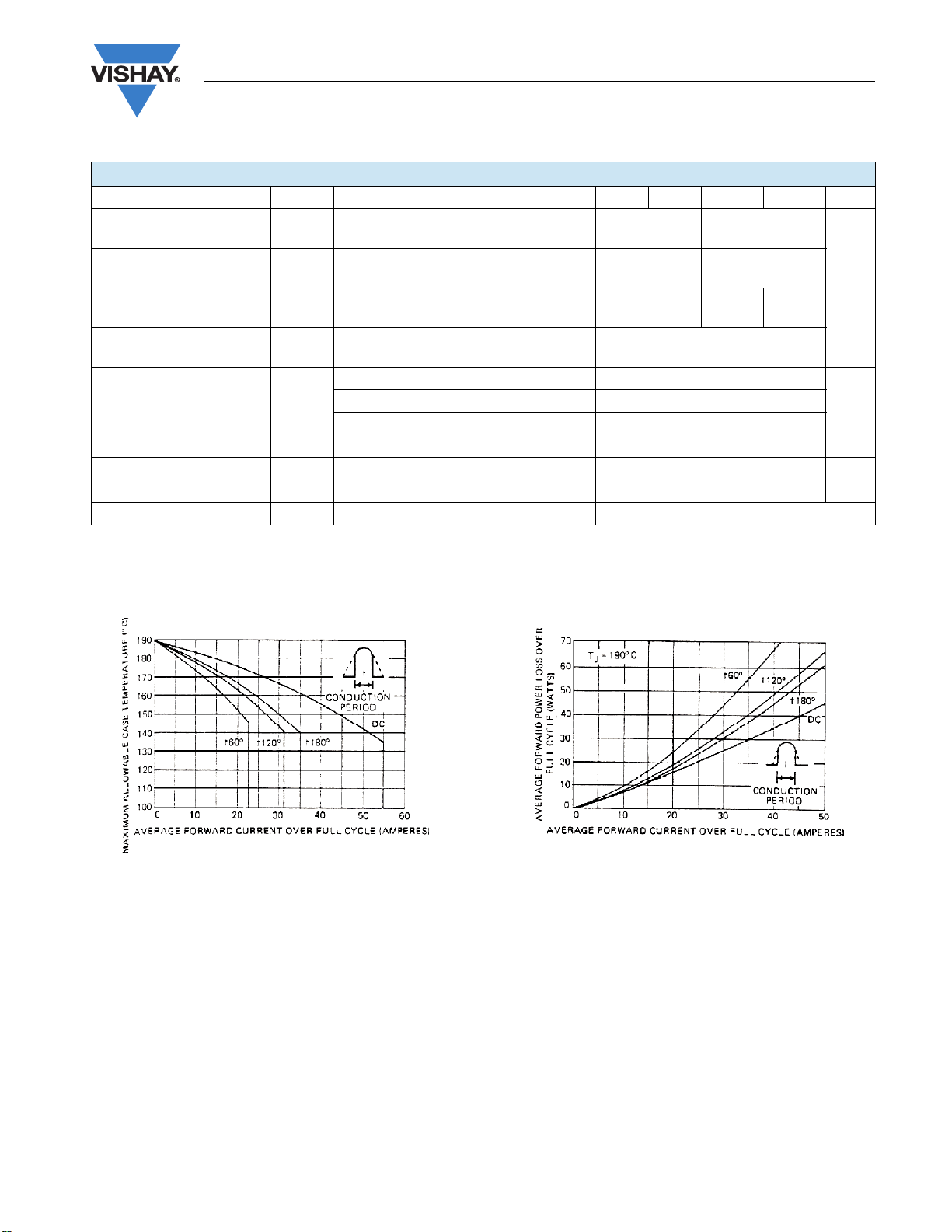
Fig. 1 - Maximum Allowable Case Temperature vs.
Average Forward Current, 1N1183 and 1N3765 Series
Fig. 2 - Typical Low Level Forward Power Loss vs.
Average Forward Current (Sinusoidal Current Waveform),
1N1183 and 1N3765 Series

1N1183, 1N3765, 1N1183A, 1N2128A Series
Vishay High Power Products
Fig. 3 - Typical High Level Forward Power Loss vs.
Average Forward Current (Sinusoidal Current Waveform),
1N1183 and 1N3765 Series
Power Silicon Rectifier Diodes,
35 A/40 A/60 A
Fig. 6 - Average Forward Current vs. Maximum Allowable
Case Temperature, 1N1183A Series
Fig. 4 - Typical Forward Voltage vs. Forward Current,
1N1183 and 1N3765 Series
Fig. 5 - Maximum Non-Repetitive Surge Current vs.
Number of Current Pulses, 1N1183 and 1N3765 Series
Fig. 7 - Maximum Low Level Forward Power Loss vs.
Average Forward Current, 1N1183A Series
Fig. 8 - Maximum High Level Forward Power Loss vs.
Average Forward Current, 1N1183A Series

1N1183, 1N3765, 1N1183A, 1N2128A Series
Power Silicon Rectifier Diodes,
35 A/40 A/60 A
Fig. 9 - Maximum Forward Voltage vs. Forward Current,
1N1183A Series
Vishay High Power Products
Fig. 12 - Maximum Allowable Case Temperature vs.
Average Forward Current, 1N2128A Series
Fig. 10 - Maximum Non-Repetitive Surge Current vs.
Number of Current Pulses, 1N1183A Series
Fig. 11 - Maximum Non-Repetitive Surge Current vs.
Number of Current Pulses, 1N2128A Series
Fig. 13 - Maximum Low Level Forward Power Loss vs.
Average Forward Current, 1N2128A Series
Fig. 14 - Maximum High Level Forward Power Loss vs.
Average Forward Current, 1N2128A Series

1N1183, 1N3765, 1N1183A, 1N2128A Series
Vishay High Power Products
Fig. 15 - Maximum Forward Voltage vs. Forward Current,
Power Silicon Rectifier Diodes,
35 A/40 A/60 A
1N2128A Series

1N1183, 1N3765, 1N1183A, 1N2128A, 1N3208 Series
DIMENSIONS in millimeters (inches)
25.4 (1.0) MAX.
DO-203AB (DO-5) for
Ø 14.6 (0.57)
6.1 (0.24)
7.0 (0.28)
Ø 4.10 (0.16)
Ø 3.80 (0.15)
4 (0.16) MIN.
10.8 (0.43)
11.4 (0.45)
Outline Dimensions
Vishay High Power Products
1.03 (0.04)
MAX.
10.7 (0.42)
11.5 (0.45)
1.0 (0.04)
MAX.
1/4" 28UNF-2A
for metric devices: M6 x 1
17.40 (0.68) MIN.
Across flats

Legal Disclaimer Notice
Vishay
Disclaimer
All product specifications and data are subject to change without notice.
Vishay Intertechnology, Inc., its affiliates, agents, and employees, and all persons acting on its or their behalf
(collectively, “Vishay”), disclaim any and all liability for any errors, inaccuracies or incompleteness contained herein
or in any other disclosure relating to any product.
Vishay disclaims any and all liability arising out of the use or application of any product described herein or of any
information provided herein to the maximum extent permitted by law. The product specifications do not expand or
otherwise modify Vishay’s terms and conditions of purchase, including but not limited to the warranty expressed
therein, which apply to these products.
No license, express or implied, by estoppel or otherwise, to any intellectual property rights is granted by this
document or by any conduct of Vishay.
The products shown herein are not designed for use in medical, life-saving, or life-sustaining applications unless
otherwise expressly indicated. Customers using or selling Vishay products not expressly indicated for use in such
applications do so entirely at their own risk and agree to fully indemnify Vishay for any damages arising or resulting
from such use or sale. Please contact authorized Vishay personnel to obtain written terms and conditions regarding
products designed for such applications.
Product names and markings noted herein may be trademarks of their respective owners.
 Loading...