

查询173D供应商
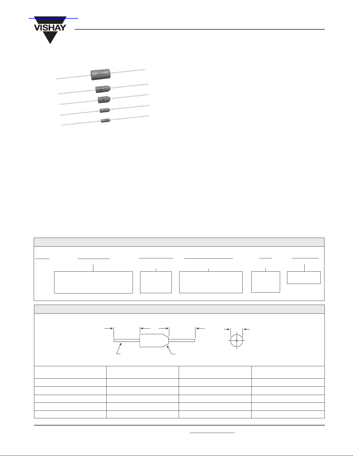
Solid-Electrolyte TANTALEX® Capacitors,
Axial-Leaded, Molded-Case
PERFORMANCE CHARACTERISTICS
Operating Temperature: - 55°C to + 85°C. (To + 125°C
with voltage derating.)
Capacitance Tolerance: At 120 Hz, + 25°C. ± 20%, ±10%
standard. ± 5% available as special.
Dissipation Factor: At 120 Hz, + 25°C. Dissipation factor,
as determined from the expression 2πfRC, shall not exceed
the values listed in the Standard Ratings Tables.
DC Leakage Current (DCL Max.):
At + 25
listed in the Standard Ratings Tables.
At + 85
values listed in the Standard Ratings Tables.
°C: Leakage current shall not exceed the values
°C: Leakage current shall not exceed 10 times the
173D
Vishay Sprague
FEATURES
• Miniature axial-lead capacitors available in 5 sizes
• Precision molded in gold colored, flame retardant, thermosetting epoxy resin
• Laser marked for improved legibility and tapered end of
case provides easy identification of positive terminal
• Standard orders are lead taped and reeled; orders under
500 are taped only.
APPLICATIONS
• Designed for high performance automotive, industrial and
commercial electronic equipment
At + 125°C: Leakage current shall not exceed 15 times
the values listed in the Standard Ratings Tables.
Life Test: Capacitors shall withstand rated DC voltage
applied at + 85°C for 2000 hours and for 1000 hours applied
at + 125°C derated voltage.
Following the life test:
1. DCL shall not exceed 125% of the initial requirement.
2. Dissipation Factor shall meet the initial requirement.
3. Change in capacitance shall not exceed ± 10%.
ORDERING INFORMATION
173D
MODEL
This is expressed in picofarads. The
first two digits are the significant
figures. The third is the number of
335
CAPACITANCE
zeros to follow.
DIMENSIONS in inches [millimeters]
0.875 [22.23]
Min.
Tinned Solid
Leads
CASE
CODE
U
V
W
X
Y
CAPACITANCE
TOLERANCE
X0 = ± 20%
X9 = ±10%
*X5 = ± 5%
*Special order
(-)
D
(MAX.)
0.095 [2.41]
0.110 [2.79]
0.180 [4.57]
0.180 [4.57]
0.280 [7.11]
X9
L
Max.
006
DC VOLTAGE RATING
AT + 85°C
This is expressed in volts.
To complete the three-digit
block, zeros precede the
voltage rating.
0.875 [22.23]
Min.
(+)
Tapered End
Identifies Anode
(MAX.)
0.260 [6.60]
0.290 [7.37]
0.345 [8.76]
0.420 [10.67]
0.550 [13.97]
U
CASE
CODE
See Ratings
and Case
Codes
Table.
D
Max.
L
LEAD
DIAMETER
0.020 [0.51]
0.020 [0.51]
0.020 [0.51]
0.020 [0.51]
0.025 [0.64]
W
PACKAGING
W = Tape and
reel.
Document Number: 40019
Revision 13-Jun-02
For technical questions, contact tantalum@vishay.com
www.vishay.com
87

173D
Vishay Sprague
Solid-Electrolyte TANTALEX® Capacitors,
Axial-Leaded, Molded-Case
STANDARD RATINGS
CAPACITANCE
µF)
(
6.8
8.2
10.0
12.0
15.0
18.0
22.0
27.0
33.0
39.0
47.0
56.0
68.0
4.7
5.6
6.8
8.2
10.0
12.0
15.0
18.0
22.0
27.0
33.0
39.0
47.0
56.0
68.0
3.3
3.9
4.7
5.6
6.8
8.2
10.0
12.0
15.0
18.0
22.0
27.0
33.0
39.0
47.0
56.0
68.0
82.0
100.0
120.0
150.0
180.0
220.0
270.0
330.0
*Part number should include "X5" for ± 5% units (special order).
CASE
CODE
2 WVDC @ + 85°C, SURGE = 2.5 V . . . 1.5 WVDC @ + 125°C, SURGE = 1.8 V
U
U
U
V
V
V
V
V
V
W
W
W
W
4 WVDC @ + 85°C, SURGE = 5 V . . . 2.5 WVDC @ + 125°C, SURGE = 3 V
U
U
U
V
V
V
V
V
V
W
W
W
W
X
X
6 WVDC @ + 85°C, SURGE = 8 V . . . 4 WVDC @ + 125°C, SURGE = 5 V
U
U
U
V
V
V
V
V
V
W
W
W
W
X
X
X
X
Y
Y
Y
Y
Y
Y
Y
Y
PART NUMBER*
CAP. TOL.
173D685X0002U
173D106X0002U
173D156X0002V
173D226X0002V
173D336X0002V
173D476X0002W
173D686X0002W
173D475X0004U
173D685X0004U
173D106X0004V
173D156X0004V
173D226X0004V
173D336X0004W
173D476X0004W
173D686X0004X
173D335X0006U
173D475X0006U
173D685X0006V
173D106X0006V
173D156X0006V
173D226X0006W
173D336X0006W
173D476X9006X
173D686X0006X
173D107X0006Y
173D157X0006Y
173D227X0006Y
173D337X0006Y
± 20%
—
—
—
—
—
—
—
—
—
—
—
—
—
—
—
—
—
—
—
—
—
—
—
—
—
PART NUMBER*
CAP. TOL. ± 10%
173D685X9002U
173D825X9002U
173D106X9002U
173D126X9002V
173D156X9002V
173D186X9002V
173D226X9002V
173D276X9002V
173D336X9002V
173D396X9002W
173D476X9002W
173D566X9002W
173D686X9002W
173D475X9004U
173D565X9004U
173D685X9004U
173D825X9004V
173D106X9004V
173D126X9004V
173D156X9004V
173D186X9004V
173D226X9004V
173D276X9004W
173D336X9004W
173D396X9004W
173D476X9004W
173D566X9004X
173D686X9004X
173D335X9006U
173D395X9006U
173D475X9006U
173D565X9006V
173D685X9006V
173D825X9006V
173D106X9006V
173D126X9006V
173D156X9006V
173D186X9006W
173D226X9006W
173D276X9006W
173D336X9006W
173D396X9006X
173D476X9006X
173D566X9006X
173D686X9006X
173D826X9006Y
173D107X9006Y
173D127X9006Y
173D157X9006Y
173D187X9006Y
173D227X9006Y
173D277X9006Y
173D337X9006Y
MAX. DCL
@ + 25°C
(µA)
0.5
0.5
0.5
0.5
0.5
0.5
0.5
0.5
0.5
0.6
0.8
0.9
1.1
0.5
0.5
0.5
0.5
0.5
0.5
0.5
0.6
0.7
0.9
1.1
1.2
1.5
1.5
2.2
0.5
0.5
0.5
0.5
0.5
0.5
0.5
0.6
0.7
0.9
1.1
1.3
1.5
1.9
2.3
2.7
3.3
3.9
4.8
5.0
5.0
8.6
10.0
10.0
10.0
MAX. DF
@ + 25°C
120 Hz
(%)
10
10
10
10
10
10
10
10
10
10
10
10
10
8
8
8
8
8
8
8
8
8
8
8
8
8
8
8
4
4
4
4
6
6
6
6
6
6
6
6
6
6
6
6
6
8
8
8
8
8
8
8
8
www.vishay.com
88
For technical questions, contact tantalum@vishay.com
Document Number: 40019
Revision 13-Jun-02

173D
STANDARD RATINGS
CAPACITANCE
(µF)
2.2
2.7
3.3
3.9
4.7
5.6
6.8
8.2
10.0
12.0
15.0
18.0
22.0
27.0
33.0
39.0
47.0
56.0
68.0
82.0
100.0
120.0
150.0
180.0
220.0
CASE
CODE
Solid-Electrolyte TANTALEX® Capacitors,
Axial-Leaded, Molded-Case
PART NUMBER*
CAP. TOL.
10 WVDC @ + 85°C, SURGE = 13 V . . . 7 WVDC @ + 125°C, SURGE = 9 V
U
U
U
V
V
V
V
V
V
W
W
W
W
X
X
X
X
Y
Y
Y
Y
Y
Y
Y
Y
173D225X0010U
173D335X0010U
173D475X0010V
173D685X0010V
173D106X0010V
173D156X0010W
173D226X0010W
173D336X0010X
173D476X0010X
173D686X0010Y
173D107X0010Y
173D157X0010Y
173D227X0010Y
± 20%
—
—
—
—
—
—
—
—
—
—
—
—
PART NUMBER*
CAP. TOL. ± 10%
173D225X9010U
173D275X9010U
173D335X9010U
173D395X9010V
173D475X9010V
173D565X9010V
173D685X9010V
173D825X9010V
173D106X9010V
173D126X9010W
173D156X9010W
173D186X9010W
173D226X9010W
173D276X9010X
173D336X9010X
173D396X9010X
173D476X9010X
173D566X9010Y
173D686X9010Y
173D826X9010Y
173D107X9010Y
173D127X9010Y
173D157X9010Y
173D187X9010Y
173D227X9010Y
MAX. DCL
@ + 25
Vishay Sprague
MAX. DF
@ + 25°C
120 Hz
(µA)
0.5
0.5
0.5
0.5
0.5
0.5
0.5
0.7
0.8
1.0
1.2
1.4
1.5
2.2
2.6
3.1
3.8
4.4
5.0
5.0
8.0
9.6
10.0
10.0
10.0
°C
(%)
4
4
4
4
4
4
6
6
6
6
6
6
6
6
6
6
6
6
6
8
8
8
8
8
8
15 WVDC @ + 85°C, SURGE = 20 V . . . 10 WVDC @ + 125°C, SURGE = 12 V
1.5
1.8
2.2
2.7
3.3
3.9
4.7
5.6
6.8
8.2
10.0
12.0
15.0
18.0
22.0
27.0
33.0
39.0
47.0
56.0
68.0
82.0
100.0
120.0
150.0
*Part number should include "X5" for ± 5% units (special order).
U
U
U
V
V
V
V
V
V
W
W
W
W
X
X
X
X
Y
Y
Y
Y
Y
Y
Y
Y
173D155X0015U
—
173D225X0015U
—
173D335X0015V
—
173D475X0015V
—
173D685X0015V
—
173D106X0015W
—
173D156X0015W
—
173D226X9015X
—
173D336X0015X
—
173D476X0015Y
—
173D686X0015Y
—
173D107X0015Y
—
173D157X0015Y
173D155X9015U
173D185X9015U
173D225X9015U
173D275X9015V
173D335X9015V
173D395X9015V
173D475X9015V
173D565X9015V
173D685X9015V
173D825X9015W
173D106X9015W
173D126X9015W
173D156X9015W
173D186X9015X
173D226X9015X
173D276X9015X
173D336X9015X
173D396X9015Y
173D476X9015Y
173D566X9015Y
173D686X9015Y
173D826X9015Y
173D107X9015Y
173D127X9015Y
173D157X9015Y
0.5
0.5
0.5
0.5
0.5
0.5
0.6
0.7
0.8
1.0
1.2
1.4
1.5
2.2
2.6
3.2
4.0
4.7
5.0
6.7
8.2
9.8
10.0
10.0
10.0
4
4
4
4
4
4
4
4
6
6
6
6
6
6
6
6
6
6
6
6
6
8
8
8
8
Document Number: 40019
Revision 13-Jun-02
For technical questions, contact tantalum@vishay.com
www.vishay.com
89

173D
Vishay Sprague
Solid-Electrolyte TANTALEX® Capacitors,
Axial-Leaded, Molded-Case
STANDARD RATINGS
CAPACITANCE
(µF)
1.0
1.2
1.5
1.8
2.2
2.7
3.3
3.9
4.7
5.6
6.8
8.2
10.0
12.0
15.0
18.0
22.0
27.0
33.0
39.0
47.0
56.0
68.0
82.0
100.0
0.47
0.56
0.68
0.82
1.0
1.2
1.5
1.8
2.2
2.7
3.3
3.9
4.7
5.6
6.8
8.2
10.0
12.0
15.0
18.0
22.0
27.0
33.0
39.0
47.0
*Part number should include "X5" for ± 5% units (special order).
CASE
CODE
20 WVDC @ + 85°C, SURGE = 26 V . . . 13 WVDC @ + 125°C, SURGE = 16 V
U
U
U
V
V
V
V
V
V
W
W
W
W
X
X
X
X
Y
Y
Y
Y
Y
Y
Y
Y
25 WVDC @ + 85°C, SURGE = 32 V . . . 17 WVDC @ + 125°C, SURGE = 21 V
U
U
U
U
U
V
V
V
V
V
V
W
W
W
W
W
W
X
X
Y
Y
Y
Y
Y
Y
PART NUMBER*
CAP. TOL. ± 20%
173D105X0020U
—
173D155X0020U
—
173D225X0020V
—
173D335X0020V
—
173D475X0020V
—
173D685X0020W
—
173D106X0020W
—
173D156X0020X
—
173D226X0020X
—
173D336X0020Y
—
173D476X0020Y
—
173D686X0020Y
—
173D107X0020Y
173D474X0025U
—
173D684X0025U
—
173D105X0025U
—
173D155X0025V
—
173D225X0025V
—
173D335X0025V
—
173D475X0025W
—
173D685X0025W
—
173D106X0025W
—
173D156X0025X
—
173D226X9025Y
—
173D336X0025Y
—
173D476X0025Y
PART NUMBER*
CAP. TOL. ± 10%
173D105X9020U
173D125X9020U
173D155X9020U
173D185X9020V
173D225X9020V
173D275X9020V
173D335X9020V
173D395X9020V
173D475X9020V
173D565X9020W
173D685X9020W
173D825X9020W
173D106X9020W
173D126X9020X
173D156X9020X
173D186X9020X
173D226X9020X
173D276X9020Y
173D336X9020Y
173D396X9020Y
173D476X9020Y
173D566X9020Y
173D686X9020Y
173D826X9020Y
173D107X9020Y
173D474X9025U
173D564X9025U
173D684X9025U
173D824X9025U
173D105X9025U
173D125X9025V
173D155X9025V
173D185X9025V
173D225X9025V
173D275X9025V
173D335X9025V
173D395X9025W
173D475X9025W
173D565X9025W
173D685X9025W
173D825X9025W
173D106X9025W
173D126X9025X
173D156X9025X
173D186X9025Y
173D226X9025Y
173D276X9025Y
173D336X9025Y
173D396X9025Y
173D476X9025Y
MAX. DCL
@ + 25°C
(µA)
0.5
0.5
0.5
0.5
0.5
0.5
0.5
0.6
0.8
0.9
1.1
1.3
1.6
1.9
2.4
2.9
3.5
4.3
5.0
6.2
7.5
8.9
10.0
10.0
10.0
0.5
0.5
0.5
0.5
0.5
0.5
0.5
0.5
0.5
0.5
0.7
0.8
0.9
1.1
1.4
1.5
1.5
2.4
3.0
3.6
4.4
5.4
6.6
7.8
9.4
MAX. DF
@ + 25°C
120 Hz
(%)
4
4
4
4
4
4
4
4
4
4
6
6
6
6
6
6
6
6
6
6
6
6
6
6
6
3
3
3
3
3
3
3
3
3
3
3
3
4
4
4
4
4
4
4
6
6
6
6
6
6
www.vishay.com
90
For technical questions, contact tantalum@vishay.com
Document Number: 40019
Revision 13-Jun-02

173D
Solid-Electrolyte TANTALEX® Capacitors,
Axial-Leaded, Molded-Case
STANDARD RATINGS
CAPACITANCE
(µF)
0.10
0.12
0.15
0.18
0.22
0.27
0.33
0.39
0.47
0.56
0.68
0.82
1.0
1.2
1.5
1.8
2.2
2.7
3.3
3.9
4.7
5.6
6.8
8.2
10.0
12.0
15.0
18.0
22.0
27.0
33.0
39.0
47.0
0.10
0.12
0.15
0.18
0.22
0.27
0.33
0.39
0.47
0.56
0.68
0.82
1.0
1.2
1.5
1.8
2.2
2.7
3.3
3.9
4.7
5.6
6.8
8.2
10.0
12.0
15.0
18.0
*Part number should include "X5" for ± 5% units (special order).
Document Number: 40019
Revision 13-Jun-02
CASE
CODE
35 WVDC @ + 85°C, SURGE = 46 V . . . 23 WVDC @ + 125°C, SURGE = 28 V
U
U
U
U
U
U
U
U
U
V
V
V
V
V
V
W
W
W
W
W
W
X
X
X
X
35 WVDC @ + 85°C, SURGE = 46 V . . . 23 WVDC @ + 125°C, SURGE = 28 V
Y
Y
Y
Y
Y
Y
Y
Y
50 WVDC @ + 85°C, SURGE = 65 V . . . 33 WVDC @ + 125°C, SURGE = 40 V
U
U
U
U
U
U
V
V
V
V
V
V
V
W
W
W
W
X
X
X
X
Y
Y
Y
Y
Y
Y
Y
PART NUMBER*
CAP. TOL. ± 20%
173D104X0035U
—
173D154X0035U
—
173D224X0035U
—
173D334X0035U
—
173D474X0035U
—
173D684X0035V
—
173D105X0035V
—
173D155X0035V
—
173D225X0035V
—
173D335X0035W
—
173D475X0035W
—
173D685X0035X
—
173D106X0035X
—
173D156X0035Y
—
173D226X0035Y
—
173D336X0035Y
—
173D476X0035Y
173D104X0050U
—
173D154X0050U
—
173D224X0050U
—
173D334X0050V
—
173D474X0050V
—
173D684X0050V
—
173D105X0050V
—
173D155X0050W
—
173D225X0050W
—
173D335X0050X
—
173D475X0050X
—
173D685X0050Y
—
173D106X0050Y
—
173D156X0050Y
—
For technical questions, contact tantalum@vishay.com
PART NUMBER*
CAP. TOL. ± 10%
173D104X9035U
173D124X9035U
173D154X9035U
173D184X9035U
173D224X9035U
173D274X9035U
173D334X9035U
173D394X9035U
173D474X9035U
173D564X9035V
173D684X9035V
173D824X9035V
173D105X9035V
173D125X9035V
173D155X9035V
173D185X9035W
173D225X9035V
173D275X9035W
173D335X9035W
173D395X9035W
173D475X9035W
173D565X9035X
173D685X9035X
173D825X9035X
173D106X9035X
173D126X9035Y
173D156X9035Y
173D186X9035Y
173D226X9035Y
173D276X9035Y
173D336X9035Y
173D396X9035Y
173D476X9035Y
173D104X9050U
173D124X9050U
173D154X9050U
173D184X9050U
173D224X9050U
173D274X9050U
173D334X9050V
173D394X9050V
173D474X9050V
173D564X9050V
173D684X9050V
173D824X9050V
173D105X9050V
173D125X9050W
173D155X9050W
173D185X9050W
173D225X9050W
173D275X9050X
173D335X9050X
173D395X9050X
173D475X9050X
173D565X9050Y
173D685X9050Y
173D825X9050Y
173D106X9050Y
173D126X9050Y
173D156X9050Y
173D186X9050Y
MAX. DCL
@ + 25°C
(µA)
0.5
0.5
0.5
0.5
0.5
0.5
0.5
0.5
0.5
0.5
0.5
0.5
0.5
0.5
0.5
0.5
0.6
0.8
0.9
1.1
1.3
1.6
1.9
2.3
2.8
3.3
4.2
5.0
6.2
7.5
9.2
10.0
10.0
0.5
0.5
0.5
0.5
0.5
0.5
0.5
0.5
0.5
0.5
0.5
0.5
0.5
0.5
0.6
0.7
0.9
1.1
1.3
1.6
1.9
2.2
2.7
3.2
4.0
5.0
6.0
6.0
Vishay Sprague
MAX. DF
@ + 25°C
120 Hz
(%)
3
3
3
3
3
3
3
3
3
3
3
3
3
3
3
3
3
3
4
4
4
4
4
4
4
4
6
6
6
6
6
6
6
3
3
3
3
3
3
3
3
3
3
3
3
3
3
4
4
4
4
4
4
4
4
4
4
6
6
6
6
www.vishay.com
91

173D
Vishay Sprague
Solid-Electrolyte TANTALEX® Capacitors,
Axial-Leaded, Molded-Case
TAPE AND REEL PACKAGING in inches [millimeters]
13 [330.2] DIA.
STANDARD REEL
1.126 to 3.07
[28.6 to 78.0]
I.D. REEL HUB
0.625 ± 0.062
± 1.57]
[15.88
DIA. THRU HOLE
CASE
CODE
U
V
W, X
Y
LABEL (4.a)
UNITS PER REEL
4500
4000
2500
500
COMPONENT SPACING
STANDARD REEL PACKAGING INFORMATION
1. Component Leads:
a. Component leads shall not be bent beyond 0.047"
[1.19mm] maximum from their nominal position when
measured from the leading edge of the component lead
at the inside tape edge and at the lead egress from the
component.
b. The 'C' dimension shall be governed by the overall length
of the reel packaged component. The distance between
flanges shall be 0.125" to 0.250" [3.18mm to 6.35mm]
greater than the overall component length.
2. Orientation:
a. All polarized components must be oriented to one
direction. The cathode lead tape shall be a color and the
anode lead tape shall be white.
3. Reeling:
a. Components on any reel shall not represent more than
two date codes when date code identification is required.
b. Component leads shall be positioned between pairs of
0.250" [6.35mm] tape.
c. The disposable reels have hubs with corrugated fiber
board flanges and core.
d. A minimum of 12" [304.8mm] leader of tape sh all be
provided before the first and after the last component on
the reel.
e. 50 to 60 lb. Kraft paper must be wound between layers of
components as far as necessary for component protection.
Width of paper to be 0.062" to 0.250" [1.57mm to 6.35mm]
less than the 'C' dimension of the reel.
"A"
"A"
A
0.200 ± 0.015
[5.08 ± 3.81]
0.400 ± 0.015
[10.16 ± 3.81]
0.750
[19.05]
SECTION "A" - "A"
TAPE SPACING
2.062 ± 0.062
[52.37 ± 1.57]
C
(1.b)
B
COMPONENT OVERALL
1.374 to 3.626
[34.9 to 92.1]
(1.a)
LENGTH (1.b)
B
0.031 [0.79] (3.f)
(BOTH SIDES) (3.f)
TAPE
SPACING
COMPONENT
SPACING (4.b)
A
0.047 [1.19] MAX.
OFF CENTER (1.a)
0.125 [3.18] MAX.
0.250 [6.35] (3.b)
f. Row components must be centered between tapes
± 0.047" [1.19mm]. In addition, individual components
may deviate from center of component row ± 0.031" [0.79].
g. Staples shall not be used for splicing. Not more than 4
layers of tape shall be used in any splice area and no
tape shall be offset from another by more than 0.031"
[0.79mm] non-cumulative. Tape splices shall overlap at
least 6" [152.4mm] for butt joints and at least 3" [76.2mm]
for lap joints and shall not be weaker than unspliced tape.
Universal splicing clips may also be used.
h. Quantity per reel shall be controlled so that tape
components and cover shall not extend beyond the
smallest dimension of the flange (either across flats or
diameter). Once the quantity per reel for each part number
has been established, future orders for that part number
shall be packaged in that quantity. When order release
quantity is less than the established quantity, a standard
commercial pack is to be used.
i. A maximum of 0.25% of the components per reel quantity
may be missing without consecutive missing components.
j. Adequate protection must be provided to prevent physical
damage to both reel and components during shipment
and storage.
4. Marking:
a. Minimum reel and carton marking shall consist of the
following: Customer Part Number, Purchase Order No.,
Quantity, Package Date, Manufacturer's name, Electrical
Value, Date Code, Vishay Sprague Part Number and
Country of Origin.
www.vishay.com
92
For technical questions, contact tantalum@vishay.com
Document Number: 40019
Revision 13-Jun-02
 Loading...