

Page 1
viscount
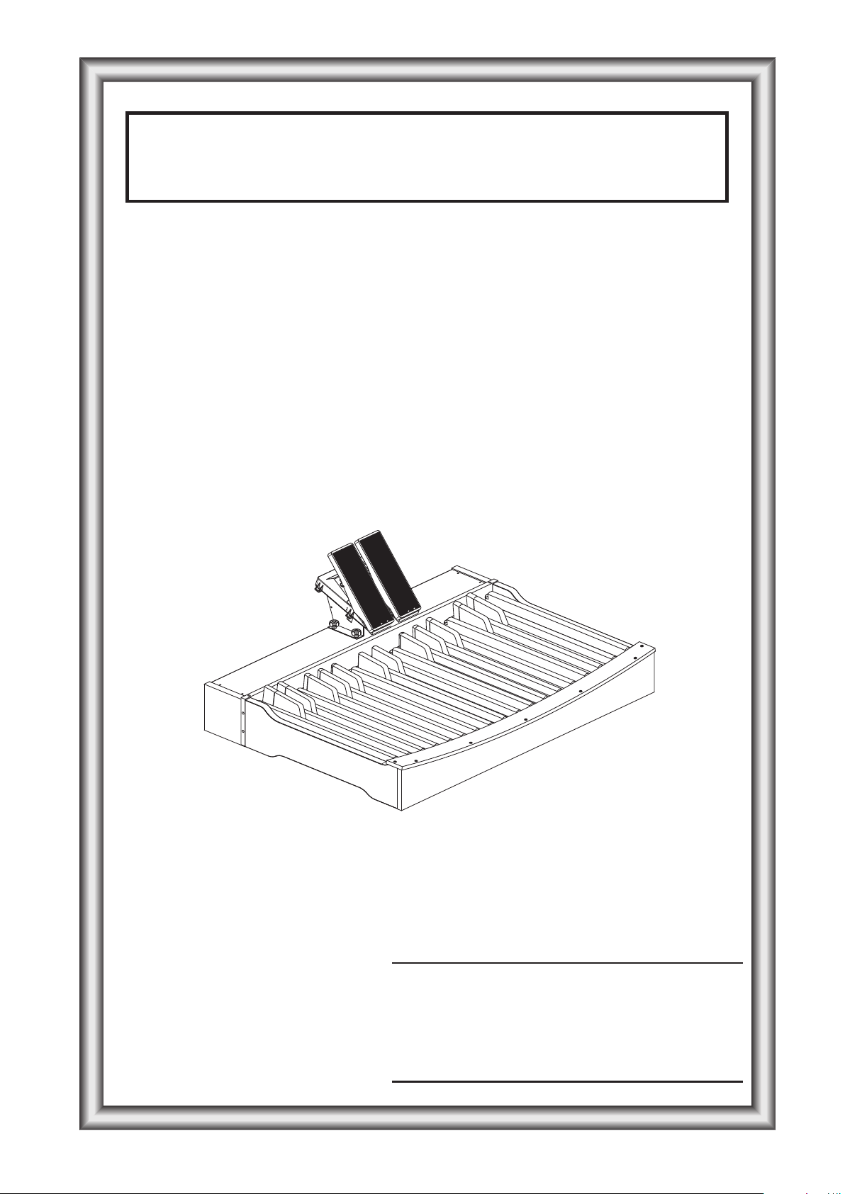
MIDI-Pedalboard
Manuale d’uso - IT
User Manual - EN
Bedienungsanleitung - DE
Ver. 1.1
Page 2
Page 3

Viscount MIDI-Pedalboard IT
INDICE
1. Controlli e connettori del pannello posteriore ......................................................................................2
2. Normale funzionamento .......................................................................................................................3
3. Configurazione dello strumento (modalità Set) ...................................................................................4
4. Funzioni di configurazione...................................................................................................................5
5. Midi Bulk Dump...................................................................................................................................7
6. Caricamento del sistema operativo.......................................................................................................8
7. Factory Setting......................................................................................................................................8
8. Schema di assemblaggio.......................................................................................................................9
1
Page 4
Viscount MIDI-PedalboardIT
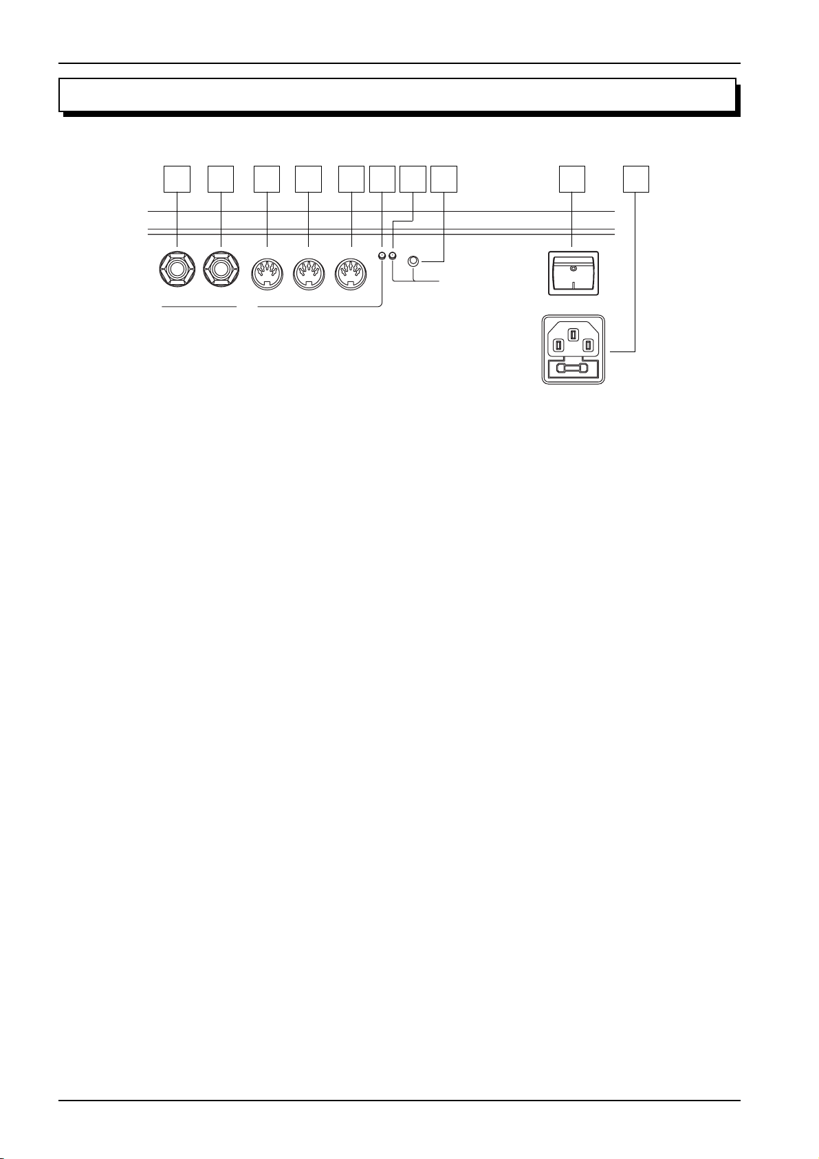
1. CONTROLLI E CONNETTORI DEL PANNELLO POSTERIORE
1 2 3 4 5 6 7 8 9 10
SET
EXPR. 2 EXPR. 1 MIDI
OUT
INPUT 2 INPUT 1
POWER
AC-IN
Sul lato posteriore della pedaliera, sotto i pedali di espressione, sono collocati tutti i controlli ed i connettori
necessari al collegamento ed al funzionamento dello strumento.
1. [EXPR. 2]: collegare qui il connettore jack del cavo proveniente dal pedale destro.
2. [EXPR. 1]: collegare qui il connettore jack del cavo proveniente dal pedale sinistro.
3. [MIDI OUT]: connettore Midi dal quale vengono trasmessi i dati generati dalla pedaliera e quelli
ricevuti dalle due prese Midi [INPUT].
4. [INPUT 2]: seconda presa Midi di ingresso alla quale collegare un generatore di dati Midi esterno.
5. [INPUT 1]: prima presa Midi di ingresso alla quale collegare un generatore di dati Midi esterno.
6. Led verde: led di visualizzazione dei dati Midi trasmessi.
7. Led rosso: led di visualizzazione della modalità Set.
8. [SET]: pulsante di attivazione della modalità Set.
9. [POWER]: pulsante di accensione della pedaliera Midi.
10.[AC-IN]: connettore al quale collegare il cavo di alimentazione fornito con lo strumento.
2
Page 5
Viscount MIDI-Pedalboard IT
2. NORMALE FUNZIONAMENTO
All’accensione dello strumento si ha un singolo lampeggio del led rosso seguito da due lampeggi del led
verde, ora il sistema è pronto per essere utilizzato.
Ad ogni evento di nota generato dalla pedaliera o di controllo tramite i pedali di espressione in uscita
dallo strumento il led verde effettua un singolo lampeggio.
La porta [MIDI OUT] oltre ad inviare i dati Midi generati dallo strumento, ritrasmette anche quelli
ricevuti dalle due porte [INPUT 1] e [INPUT 2] (funzione Soft-Thru).
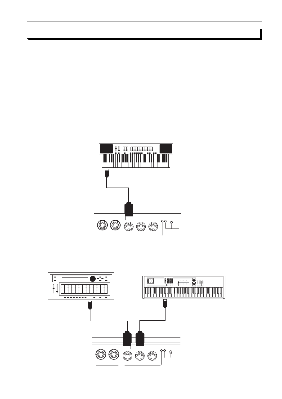
ESEMPI DI UTILIZZO
Grazie a questo funzionamento è possibile utilizzare la pedaliera Midi in diverse modalità, ad esempio:
- Pedaliera per organo che non ne è equipaggiato
Organ, Keyboard, etc...
MIDI IN
SET
EXPR. 2 EXPR. 1 MIDI
INPUT 2 INPUT 1
OUT
MIDI-Pedalboard
- Pedaliera e Midi-Thru per l’utilizzo di un generatore sonoro esterno
Expander, Midi Pipes
MIDI IN
Organ, Keyboard, Master Keyboard, Sequencer
MIDI OUT
EXPR. 2 EXPR. 1 MIDI
OUT
MIDI-Pedalboard
SET
INPUT 2 INPUT 1
3
Page 6

Viscount MIDI-PedalboardIT
3. CONFIGURAZIONE DELLO STRUMENTO (MODALITA’ SET)
Per accedere alle funzioni di configurazione dello strumento premere il pulsane [SET], il led rosso si
accende fisso. Per abbandonare la modalità Set e tornare al normale utilizzo della pedaliera Midi ripremere
il pulsante [SET], il Led rosso si spegne.
NOTA
In modalità Set lo strumento non trasmette sulla porta [MIDI OUT] le note suonate sulla pedaliera
ed i dati ricevuti dalle prese [INPUT].
In modalità Set i pedali della pedaliera non servono più per generare note ma bensì per richiamare le
funzioni di configurazione ed immettere i dati. I pedali bianchi immettono i dati numerici, quelli neri
richiamano le funzioni.
Dopo aver premuto il pulsante [SET] è sempre necessario selezionare prima la funzione desiderata (pedali neri), poi introdurre i dati con i pedali bianchi, terminata la programmazione occorre premere il terzo
Do# a funzione di conferma.
Qualora si sia premuto il pedale nero di richiamo della funzione sbagliato è sufficiente premere quello
corretto senza uscire dalla modalità Set per richiamare la funzione desiderata.
Di seguito le funzioni di configurazione previste:
- [Do#1]: unità per l’immissione dati numerici da 0 a 127
- [Re#1]: decine per l’immissione dati numerici da 0 a 127
- [Fa#1]: canale Midi di trasmissione della note suonate con la pedaliera
- [Sol#1]: valore della dinamica Midi delle note suonate con la pedaliera
- [La#1]: numero della nota Midi o del messaggio di Program Change del primo pedale (funzione
transposer)
- [Do#2]: canale Midi di trasmissione del messaggio di Control Change associato al pedale di espres-
sione [EXPR. 1]
- [Re#2]: canale Midi di trasmissione del messaggio di Control Change associato al pedale di espres-
sione [EXPR. 2]
- [Fa#2]: funzione associata (tipo di Control Change trasmesso) al pedale di espressione [EXPR. 1]
- [Sol#2]: funzione associata (tipo di Control Change trasmesso) al pedale di espressione [EXPR. 2]
- [La#2]: seleziona della modalità di funzionamento della pedaliera
La procedura per l’immissione dei dati numerici, salvo se diversamente specificato nel manuale d’uso, è
la seguente:
- dati numerici compresi tra 0 e 15: premere un pedale bianco dal [Do1] al [Re3] (il [Do1] corrispon-
de allo 0).
- dati numerici compresi tra 0 e 127: premere il [Do#1] e poi un pedale bianco tra 0 e 9 per introdurre
le unità; premere il [Re#1] e poi un pedale bianco tra 0 e 12 per introdurre le decine. Numeri superiori
a 127 vengono limitati a tale valore.
T erminata l’immissione dati premere il [Do#3] a funzione di conferma (Enter), il Led rosso si spegne e la
pedaliera Midi torna alla normale modalità di funzionamento. E’ possibile comporre diverse volte il
valore numerico desiderato prima di confermare, l’ultima immissione sarà quella accettata e memorizzata.
4
Page 7

Viscount MIDI-Pedalboard IT
ESEMPI DI PROGRAMMAZIONE
Si desidera impostare il canale di trasmissione sul 4.
1) premere il pulsante [SET]
2) premere il [Fa#1] per richiamare la funzione
3) premere il [Sol1] per immettere il numero 4
4) premere il [Do#3] per confermare
Si desidera impostare la dinamica Midi sul valore 64.
1) premere il pulsante [SET]
2) premere il [Sol#1] per richiamare la funzione
3) premere il [Do#1] per immettere le unità
4) premere il [Sol1] per immettere il numero 4
5) premere il [Re#1] per immettere le decine
6) premere il [Si1] per immettere il numero 6
7) premere il [Do#3] per confermare
4. FUNZIONI DI CONFIGURAZIONE
CANALE MIDI DI TRASMISSIONE
1) Premere il pulsante [SET]
2) Premere il [Fa#1]
3) Premere un pedale bianco da 0 a 15 (il [Do1] corrisponde allo 0)
4) Premere il [Do#3]
DINAMICA MIDI DELLE NOTE TRASMESSE
1) Premere il pulsante [SET]
2) Premere il [Sol#1]
3) Premere il [Do#1]
4) Premere un pedale bianco da 0 a 15 (il [Do1] corrisponde allo 0)
5) Premere il [Re#1]
6) Premere un pedale bianco da 0 a 12 (il [Do1] corrisponde allo 0)
7) Premere il [Do#3]
NUMERO DI NOTA O PROGRAM CHANGE ASSOCIATO AL PRIMO PEDALE
Quando la pedaliera è in modalità note (vedi par. “Impostazione della modalità di pedaliera”) questa
funzione imposta il numero della nota Midi del primo pedale. Questa funzione pertanto ha lo scopo di
regolare una trasposizione della pedaliera; si ricorda che negli organi intonati con il La3 a 440 Hz le
pedaliere trasmettono il [Do1] come nota Midi numero 36, impostando il valore 37 si ottiene una
trasposizione di +1 semitoni.
Quando la pedaliera è in modalità Program Change questa funzione imposta il numero del messaggio di
Program Change che viene trasmesso premendo il [Do1].
1) Premere il pulsante [SET]
2) Premere il [La#1]
3) Premere il [Do#1]
4) Premere un pedale bianco da 0 a 15 (il [Do1] corrisponde allo 0)
5) Premere il [Re#1]
5
Page 8

6) Premere un pedale bianco da 0 a 12 (il [Do1] corrisponde allo 0)
7) Premere il [Do#3]
NOTA
In modalità note numeri superiori a 96 vengono limitati a tale valore.
CANALE MIDI DEL PEDALE D’ESPRESSIONE [EXPR. 1]
1) Premere il pulsante [SET]
2) Premere il [Do#2]
3) Premere un pedale bianco da 0 a 15 (il [Do1] corrisponde allo 0)
4) Premere il [Do#3]
CANALE MIDI DEL PEDALE D’ESPRESSIONE [EXPR. 2]
1) Premere il pulsante [SET]
2) Premere il [Re#2]
3) Premere un pedale bianco da 0 a 15 (il [Do1] corrisponde allo 0)
4) Premere il [Do#3]
Viscount MIDI-PedalboardIT
CONTROL CHANGE TRASMESSO DAL PEDALE D’ESPRESSIONE [EXPR. 1]
1) Premere il pulsante [SET]
2) Premere il [Fa#2]
3) Premere il [Do1] per assegnare il Control Change 7 (Volume) o il [Re1] per assegnare il Control
Change 11 (Expression)
4) Premere il [Do#3]
TARATURA DEL PEDALE D’ESPRESSIONE [EXPR. 1]
1) Premere il pulsante [SET]
2) Premere il [Fa#2]
3) Premere il [Mi1] e posizionare il pedale d’espressione nella posizione minima
4) Premere il [Do#3]
5) Premere il pulsante [SET]
6) Premere il [Fa#2]
7) Premere il [Fa1] e posizionare il pedale d’espressione alla posizione massima
8) Premere il [Do#3]
CONTROL CHANGE TRASMESSO DAL PEDALE D’ESPRESSIONE [EXPR. 2]
1) Premere il pulsante [SET]
2) Premere il [Sol#2]
3) Premere il [Do1] per assegnare il Control Change 7 (Volume) o il [Re1] per assegnare il Control
Change 11 (Expression)
4) Premere il [Do#3]
TARATURA DEL PEDALE D’ESPRESSIONE [EXPR. 2]
1) Premere il pulsante [SET]
2) Premere il [Sol#2]
3) Premere il [Mi1] e posizionare il pedale d’espressione nella posizione minima
4) Premere il [Do#3]
5) Premere il pulsante [SET]
6
Page 9

Viscount MIDI-Pedalboard IT
6) Premere il [Sol#2]
7) Premere il [Fa1] e posizionare il pedale d’espressione alla posizione massima
8) Premere il [Do#3]
MODALITA’ DI FUNZIONAMENTO DELLA PEDALIERA (monofonica, polifonica, invio di
Program Change)
1) Premere il pulsante [SET]
2) Premere il [La#2]
3) Premere:
- [Do1] per impostare la modalità polifonica
- [Re1] per la modalità monofonica con priorità dell’ultima nota suonata
- [Mi1] per la modalità monofonica con priorità della nota più grave
- [Fa1] per la modalità di invio di messaggio di Program Change (in questa modalità i pedali della
pedaliera non trasmettono eventi di nota ma Program Change, vedi anche il par. “Numero di nota
o Program Change associato al primo pedale)
4) Premere il [Do#3]
5. MIDI BULK DUMP
Il Midi Bulk Dump è un pacchetto di dati contenente la configurazione dello strumento ovvero lo stato
delle funzioni precedentemente descritte. Salvare questo pacchetto di dati in un’unità esterna permette di
crearsi e disporre di più configurazioni ripristinabili in qualsiasi momento. Tale funzione ha altresì lo
scopo di crearsi un backup della configurazione della pedaliera qualora per motivi accidentali la memoria interna venga cancellata o rovinata.
TRASMISSIONE
Per trasmettere sulla porta [MIDI OUT] (connessa alla porta Midi In di un dispositivo di acquisizione
Midi quali un sequencer) la configurazione dello strumento premere il pulsante [SET] poi [Re3].
Al termine della trasmissione dei dati il Led rosso si spegne.
RICEZIONE
Per acquisire un Midi Bulk Dump precedentemente trasmesso e registrato, collegare la porta Midi Out di
un lettore Midi o un sequencer alla [INPUT 1] o [INPUT 2] della pedaliera Midi.
Una volta effettuati i collegamenti premere il pulsante [SET] e avviare la trasmissione dal dispositivo
Midi esterno. Al termine della ricezione lo strumento esegue una verifica dei dati (onde evitare di rendere
inutilizzabile la pedaliera) passata la quale il Bulk Dump ricevuto viene memorizzato, a conferma di ciò
il Led rosso si spegne. Qualora i dati ricevuti non sono corretti il Led rosso lampeggia due volte.
7
Page 10

Viscount MIDI-PedalboardIT
6. AGGIORNAMENTO DEL SISTEMA OPERA TIV O
Il sistema operativo dello strumento viene fornito tramite un file Midi (file .mid). Per caricare lo stesso
nella pedaliera è necessario disporre di un lettore Midi la cui porta Midi Out è da collegare alla [INPUT
1] (no la [INPUT 2]) della pedaliera. Durante la ricezione dei dati il led verde lampeggia, al temine del
caricamento viene eseguita una verifica dei dati passata la quale il Led verde si spegne e quello rosso
lampeggia una volta. Qualora la verifica non vada a buon fine il Led rosso indica l’errore tramite una
serie di lampeggi:
- due lampeggi: errore per perdita di dati
- tre lampeggi: errore per checksum errato
- quattro lampeggi: errore generico
In questo caso tentare di caricare nuovamente il sistema operativo, controllando che i cavi Midi siano di
buona qualità e che il lettore non generi errori in lettura del file. Per caricare il sistema operativo a
strumento non funzionante accenderlo tenendo premuto il pulsante [SET], il Led rosso lampeggia una
volta. Qualora non sia possibile caricare il sistema operativo contattare il centro di assistenza comunicando l’errore riscontrato.
7. FACTORY SETTING
La procedura di Factory Settings permette di ripristinare le funzioni di configurazione dello strumento
con i valori iniziali di fabbrica. Per fare ciò tenere premuto per almeno 10 secondi il pulsante [SET], al
termine dell’operazione il Led rosso effettua due lampeggi.
Le impostazioni di fabbrica sono le seguenti:
- Canale Midi di trasmissione: 4
- Dinamica Midi delle note trasmesse: 64
- Numero di nota del primo pedale: 36
- Numero Program Change del primo pedale: 1
- Canale Midi del pedale d’espressione [EXPR. 1]: 2
- Canale Midi del pedale d’espressione [EXPR. 2]: 1
- Control Change del pedale d’espressione [EXPR. 1]: 11 (Expression)
- Control Change del pedale d’espressione [EXPR. 2]: 11 (Expression)
- Modalità di funzionamento della pedaliera: polifonica
8
Page 11
Viscount MIDI-Pedalboard IT
R
W
T
0
0
0
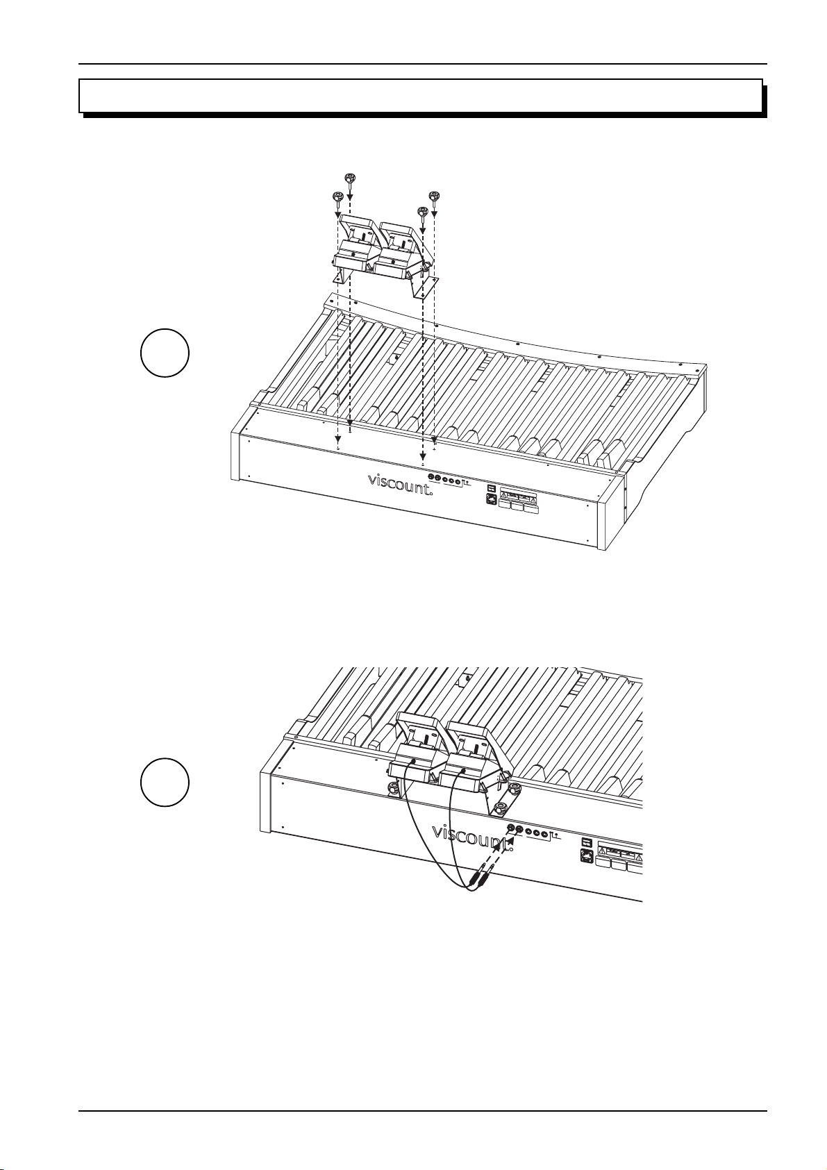
8. SCHEMA DI ASSEMBLAGGIO
1
2
MIDI-Pedalboard
EXPR.2
EXPR.1
MIDI
INPUT2
SET
O
UT
INPUT1
M
IDI-Pedalboard
T
H
I
S
D
E
V
I
C
E
C
O
C
M
O
N
P
D
L
I
I
E
T
S
I
O
W
N
I
S
T
:
H
1
.
PA
T
A
H
N
R
I
Y
S
T1
I
D
N
5
E
T
V
O
E
I
R
F
C
F
E
T
E
H
M
R
E
A
E
YN
F
N
C
C
C
E
O
R
T
R
U
E
C
L
C
A
E
E
U
S
I
S
V
.
E
E
O
D
P
H
,
E
A
I
R
R
N
A
M
C
T
L
F
I
U
O
U
D
L
N
I
PO
I
N
I
N
S
G
T
S
E
I
U
N
R
W
B
T
F
E
J
E
E
R
R
ER
C
F
E
T
E
N
R
TOT
C
E
E
N
,
A
C
H
N
E
E
D
T
F
2
H
O
.
T
A
L
H
TM
L
I
O
S
W
A
D
YC
I
E
N
V
G
A
I
C
T
U
E
W
S
M
E
0
U
U
S
N
T
D
A
E
C
S
I
C
R
E
E
P
D
T
O
P
E
R
A
T
I
O
RISK
N
.
O
F
E
LEC
TR
TO
IC
S
R
HO
ED
D
O
C
U
K
NO
CE
T
TH
O
PE
E
R
RISK
ISQ
N
U
O
E
FF
D
E
IR
CH
EO
`
O
C
R
E
E
LE
LE
CT
C
N
TR
E
R
IQ
IC
P
AS
U
SH
E
O
O
U
C
VRIR
K,D
ATTENTIO
O
NO
T
EX
PO
SE
T
H
IS
N
APP
LIAN
U
TILISE
C
E
TO
R
R
AIN
U
N
CAUTION FUS
FU
O
RE
R
S
MO
CH
IB
LE
A
IS
N
D
TU
GE
E
R
D
E.
E
M
EM
F
DE
OR
E
B
TY
C
RA
O
PE
N
NC
TIN
H
E
U
D
R
E
AG
AC-IN
E
D
AVA
RE
A
PR
IN
M
NT
O
S
PLA
TE
T
FIR
C
C
TION
ER
E
H
L
A
E
O
ZA
FU
NL
E
R
S
YW
D
IB
R
LE
EP
ITH
LAC
T
S
0
AM
,
2
E
A
E
D
L2
ISC
T
YP
5
O
0
E
V
N
FU
NEC
F
O
SE
R
T
S
M
S
UP
A
BE
I
N
P
L
S
F
T
YCO
OR
0
1
,
0
2
E
0
A
R
C
-
L2
D
HA
2
4
5
0
N
0
V
GI
V
NG
F
O
R
FU
M
S
E
A
I
N
S
T
0
1
,
0
2
0
A
-
L2
2
4
5
0
0
V
V
F
O
R
M
A
I
N
S
1
0
0
2
4
0
V
E
X
P
R
.
2
E
X
P
R
.
1
M
ID
I
IN
S
P
E
U
T
T
2
O
U
IN
T
P
U
T
1
T
H
I
S
D
E
V
I
C
E
C
O
C
O
M
N
P
L
D
I
I
E
T
S
I
O
W
N
S
I
T
:
H
1
.
PA
T
A
H
N
R
I
Y
S
T1
I
D
N
5
E
T
V
O
E
I
R
F
C
F
E
T
E
H
M
R
E
A
E
YN
F
N
C
C
C
E
O
R
T
R
U
E
C
L
C
A
E
E
U
S
I
S
V
.
E
O
E
D
P
H
,
E
A
I
R
R
N
A
M
C
T
L
F
I
U
O
U
D
L
P
O
A
C
N
I
I
N
I
N
S
G
T
S
E
I
U
N
R
W
IN
B
T
F
E
J
E
E
R
R
E
R
C
F
E
T
E
N
R
TOT
C
E
E
N
,
A
C
H
N
E
E
D
T
F
2
H
O
.
A
T
L
TM
H
L
I
O
S
W
A
D
YC
I
E
N
V
G
A
I
C
T
U
E
S
M
E
U
U
S
N
T
D
A
E
C
S
C
I
R
E
E
P
D
O
P
E
R
A
T
I
O
R
N
I
S
.
K
O
F
E
L
E
C
T
R
I
TO
C
S
R
H
E
D
O
D
O
C
U
K
N
C
O
E
T
T
O
H
P
E
R
E
R
I
N
S
I
S
Q
K
U
O
E
F
D
F
E
I
R
C
E
H
O
`
O
C
R
E
E
L
L
E
E
C
C
N
T
T
R
E
R
I
I
Q
P
C
A
U
S
S
E
H
O
O
U
C
V
K
R
,
I
D
R
AT
O
N
O
T
T
E
E
X
N
P
O
T
S
E
IO
T
H
I
N
S
A
P
P
L
I
A
N
U
C
T
I
E
L
I
TO
S
E
R
R
A
U
I
N
C
N
F
O
U
A
R
R
S
E
U
M
I
C
B
H
O
L
T
A
E
I
S
N
D
T
IO
G
U
E
E
D
N
E
M
E
F
M
D
O
E
E
R
B
T
C
R
Y
O
A
P
N
N
E
T
C
I
H
N
E
U
D
R
E
A
E
D
G
AVA
R
A
P
E
I
R
N
M
N
O
S
T
P
T
T
L
E
A
F
C
C
I
R
F
T
E
E
I
R
O
U
H
N
L
A
E
S
O
Z
F
A
N
U
E
R
L
S
YW
D
I
B
R
L
E
I
E
T
P
H
L
T
A
S
0
C
A
,
2
E
M
A
E
D
L2
I
T
S
Y
C
5
P
O
0
E
V
N
F
N
F
U
E
O
S
C
E
R
T
S
S
M
U
A
P
B
I
P
N
E
L
S
F
T
YC
O
0
1
R
,
0
2
O
E
0
A
R
C
-
L2
D
H
2
A
4
5
N
0
G
V
I
N
F
G
O
F
R
U
M
S
E
A
I
N
S
T
0
1
,
0
2
0
A
-
L2
2
4
5
0
V
F
O
R
M
A
I
N
S
1
0
0
2
4
9
Page 12
Smaltimento dei rifiuti elettrici ed elettronici (applicabile nell’Unione Europea e negli altri paesi
europei con servizio di raccolta differenziata)
Ai sensi dell’art. 13 del Decreto legislativo 25 luglio 2005, n. 151 “Attuazione delle Direttive
2002/95/CE, 2002/96/CE e 2003/108/CE”
II simbolo presente sul prodotto o sulla sua confezione indica che il prodotto non verrà trattato come
rifiuto domestico. Sarà invece consegnato al centro di raccolta autorizzato per il riciclo dei rifi uti
elettrici ed elettronici. Assicurandovi che il prodotto venga smaltito in modo adeguato, eviterete un
potenziale impatto negativo sull’ambiente e la salute umana, che potrebbe essere causato da una
gestione non conforme dello smaltimento del prodotto. Il riciclaggio dei materiali contribuirà alla
conservazione delle risorse naturali. Per ricevere ulteriori informazioni più dettagliate Vi invitiamo a
contattare l’uffi cio preposto nella Vostra città, il servizio per lo smaltimento dei rifi uti o il negozio in
cui avete acquistato il prodotto.
Lo smaltimento del prodotto da parte dell’utente comporta l’applicazione delle sanzioni amministrative
previste dalla normativa di legge.
Questo prodotto è conforme ai requisiti delle direttive EMCD 2004/108/EC e LVD 2006/95/EC.
Page 13

Page 14

Page 15

Viscount MIDI-Pedalboard EN
ANNEX
1. Controls and connections on the rear panel........................................................................................14
2. Play mode ...........................................................................................................................................15
3. Instrument configuration (Set mode)..................................................................................................16
4. Configuration functions ......................................................................................................................17
5. Midi Bulk Dump.................................................................................................................................19
6. Operating system updating .................................................................................................................20
7. Factory Setting....................................................................................................................................20
8. Assembly scheme ...............................................................................................................................21
13
Page 16

Viscount MIDI-PedalboardEN
1. CONTROLS AND CONNECTIONS ON THE REAR PANEL
1 2 3 4 5 6 7 8 9 10
SET
EXPR. 2 EXPR. 1 MIDI
OUT
INPUT 2 INPUT 1
POWER
AC-IN
The rear panel of the pedalboard contains all controls and connections.
1. [EXPR. 2]: for connecting the cable of the right expression pedal.
2. [EXPR. 1]: for connecting the cable of the left expression pedal.
3. [MIDI OUT]: Midi socket for the transmission of the Midi data generated by the pedalboard and
received by the two [INPUT] Midi sockets.
4. [INPUT 2]: second Midi input socket for the connection of an external Midi data generator.
5. [INPUT 1]: first Midi input socket for the connection of an external Midi data generator.
6. Green led: Led showing Midi data transmission on [MIDI OUT].
7. Red led: Led showing Set mode.
8. [SET]: button for switching the Set mode.
9. [POWER]: for switching the pedalboard on and off.
10. [AC-IN]: power supply connection.
14
Page 17

Viscount MIDI-Pedalboard EN
2. PLAY MODE
When on, the red Led flashes one time and the green Led flashes twice. This indicates that the system is
ready for use.
Every time a note is played on the pedalboard or the expression pedals are in use, the green Led flashes
one time.
The [MIDI OUT] port, in addition to the MIDI data transmission, also transmits the Midi data received
through [INPUT 1] and [INPUT 2] (Soft-Thru function) Midi sockets.
EXAMPLES
This function permits to use the Midi pedalboard in different ways, i.e:
- with organs not equipped with a pedalboard
Organ, Keyboard, etc...
MIDI IN
SET
EXPR. 2 EXPR. 1 MIDI
INPUT 2 INPUT 1
OUT
MIDI-Pedalboard
- to use the Pedalboard and Midi-Thru with an external sound generator
Expander, Midi Pipes
MIDI IN
Organ, Keyboard, Master Keyboard, Sequencer
MIDI OUT
EXPR. 2 EXPR. 1 MIDI
OUT
MIDI-Pedalboard
SET
INPUT 2 INPUT 1
15
Page 18

Viscount MIDI-PedalboardEN
3. INSTRUMENT CONFIGURATION (SET MODE)
For starting the instrument configuration functions, press [SET] button and the red Led will light. In
order to exit from the Set mode and to return to the play mode press again [SET] button and the red Led
light off.
NOTE
In Set mode the instrument does not transmit MIDI data.
In Set mode the pedals and the controls are used to input the data for device programming.
After having pressed [SET] button, you must first select the desired function using a black key and then
setting the data using the white keys. To complete and store the new configuration, you must press the
third C# ( in order to confirm the change).
If, having pressed the wrong key, it doesn’t select the desired function, simply press the correct key for
recalling the function.
The Set mode contains the following configuration functions:
- [C#1]: unit for numeric data entry ( from 0 to 127)
- [D#1]: tens for numeric data entry (from 0 to 127)
- [F#1]: Midi transmission channel for the notes played on the pedalboard
- [G#1]: Midi velocity value of the notes played on the pedalboard
- [A#1]: Midi note or Program Change number of the first pedal -C1 (transposer function)
- [C#2]: Midi transmission channel for Control Change in connection with the expression pedal
[EXPR. 1]
- [D#2]: Midi transmission channel for Control Change in connection with the expression pedal
[EXPR. 2]
- [F#2]: function connected (type of Control Change transmitted) to the expression pedal [EXPR. 1]
- [G#2]: function connected (type of the Control Change transmitted) to the expression pedal
[EXPR. 2]
- [A#2]: pedalbord function mode selection
The procedure for setting numeric datas, (if not differently mentioned in this manual) is the following:
- values from 0 to 15: press a white pedal from [C1] to [D3] (C1=0)
- values from 0 to 127: press [C#1] ,then a white pedal from 0 to 9 to set the units; press [D#1] then
a white pedal between 0 and 12 to set the tens. Values higher than 127 are blocked to this value.
Once the data entry procedure is completed, press [C#3] to confirm (Enter function), the red Led will
light off and the pedalboard will go back to the standard mode. It is possible to set the desired number
several times before confirmation but only the last number will be accepted and stored.
16
Page 19

Viscount MIDI-Pedalboard EN
PROGRAMMING EXAMPLES
If you wish to set transmission channel as 4.
1) press [SET] button
2) press [F#1] to recall the function
3) press [G1] to set the number 4
4) press [C#3] to confirm
If you wish to set Midi velociy as 64.
1) press the [SET] button
2) press [G#1] to recall the function
3) press [C#1] to set the unit
4) press [G1] to set the number 4
5) press [D#1] to set the tens
6) press [B1] to set the number 6
7) press [C#3] to confirm
4. CONFIGURATION FUNCTIONS
MIDI TRANSMISSION CHANNEL
1) Press the [SET] button
2) Press [F#1]
3) Press a white key from 0 to 15 ([C1] corresponds to 0)
4) Press [C#3]
MIDI VELOCITY OF TRANSMITTED NOTES
1) Press the [SET] button
2) Press [G#1]
3) Press [C#1]
4) Press a white key from 0 to 15 ([C1] corresponds to 0)
5) Press [D#1]
6) Press a white key from 0 to 12 ([C1] corresponds to 0)
7) Press [C#3]
NOTE NUMBER OR PROGRAM CHANGE CONNECTED TO THE FIRST PEDAL
When the pedalboard is in note mode (see also par. “Pedalboard function mode”) it will set the note
number of the first key. This function allows the adjustment of a transposition of the pedalboard; (please
note that with organ tuned with the A3 at 440Hz the keys will transmit C1 as Midi note 36, setting a
value of 37 for obtaining a transposition of +1 semitone.
When the pedalboard is in Program Change mode it will set the number of the Program Change transmitted
when [C1] is pressed.
1) Press [SET] button
2) Press [A#1]
3) Press [C#1]
4) Press a white key from 0 to 15 ([C1] corresponds to 0)
5) Press [D#1]
17
Page 20

6) Press a white key from 0 to 12 ([C1] corresponds to 0)
7) Press [C#3]
NOTE
In Set mode numbers higher than 96 are limited to this value
EXPRESSION PEDAL [EXPR. 1] MIDI CHANNEL
1) Press [SET] button
2) Press [C#2]
3) Press a white key from 0 to 15 ([C1] corresponds to 0)
4) Press [C#3]
EXPRESSION PEDAL [EXPR. 2] MIDI CHANNEL
1) Press [SET] button
2) Press [D#2]
3) Press a white key from 0 to 15 ([C1] corresponds to 0)
4) Press [C#3]
Viscount MIDI-PedalboardEN
CONTROL CHANGE TRANSMITTED BY THE EXPRESSION PEDAL [EXPR. 1]
1) Press [SET] button
2) Press [F#2]
3) Press [C1] to assign Control Change 7 (Volume) or [D1] to assign Control Change 11 (Expression)
4) Press [C#3]
EXPRESSION PEDAL [EXPR. 1] CALIBRATION
1) Press [SET] button
2) Press [F#2]
3) Press [E1] and set the expression pedal at minimum
4) Press [C#3]
5) Press [SET] button
6) Press [F#2]
7) Press [F1] and set the expression pedal at maximum
8) Press [C#3]
CONTROL CHANGE TRANSMITTED BY THE EXPRESSION PEDAL [EXPR. 2]
1) Press [SET] button
2) Press [G#2]
3) Press [C1] to assign Control Change 7 (Volume) or [D1] Control Change 11 (Expression)
4) Press [C#3]
EXPRESSION PEDAL [EXPR. 2] CALIBRATION
1) Press [SET] button
2) Press [G#2]
3) Press [E1] and set the expression pedal at minimum
4) Press [C#3]
5) Press [SET] button
6) Press [G#2]
7) Press [F1] and set the expression pedal at maximum
18
Page 21

Viscount MIDI-Pedalboard EN
7) Press [C#3]
PEDALBOARD FUNCTION MODE (monofonic, polifonic, Program Change transmission)
1) Press [SET] button
2) Press [A#2]
3) Press:
- [C1] to set the polifonic mode
- [D1] to set the monofonic mode with priority of the last played note
- [E1] to set the monofonic mode with priority of the lower note
- [F1] to set the Program Change transmission mode (in this mode pedals don’t transmit Midi note
but Program Change messages, see also par. “Note number or Program Change applied to the first
key”
4) Press [C#3]
5. MIDI BULK DUMP
Midi Bulk Dump is a data packet containing the instrument’s configuration, i.e the values of the functions
already described Storing these datas into an external unit gives you the possibility to create and dispose
of several pedalbord’s configurations. In addition you can create an external backup of the configuration.
TRANSMISSION
For transmitting on [MIDI OUT] port (connected to the Midi In port of a Midi device like a sequencer)
the pedalbord’s configuration press [SET] button and then the [D3]. When finished the red Led will lights
off.
RECEPTION
For receiving and storing in the internal memory a Midi Bulk Dump previously transmitted and recorded,
connect the Midi Out of a Midi data player or a sequencer to Midi pedalboard’s [INPUT 1] or [INPUT 2].
Then press [SET] button and start playing the recorded Midi Bulk Dump on the external Midi device.
When reception is terminated, the instrument will check datas (in order to avoid configuration problems).If
they are not correct, the red Led will flash twice.
19
Page 22

Viscount MIDI-PedalboardEN
6. OPERATING SYSTEM UPDATING
The operating system is supplied by Viscount as a Midi file (.mid file). For loading it into the Midi
pedalboard, you have to use a Midi data player and to connect its Midi out to the pedalboard’s [INPUT 1]
(not INPUT 2). When loading the green Led will flash, after reception the instrument will check data. If
correct the green Led lights off and the red Led will flash one time. If not correct, the red Led will flsh as
follows:
- two flashes: data are lost
- three flashes: checksum is not correct
- four flashes: generic error
In this case load again the operating system file, check the quality of Midi cables and that Midi data
player doesn’t generate errors.
For loading the operating system when Midi pedalboard is not on, switch it on pressing [SET] button and
red Led will flash one time.
If it is not possible to load data please contact a service center informing about the error occurred (how
many times the red Led has flashed).
7. FACTORY SETTING
The Factory Setting procedure allows you to restore the factory configuration of internal functions, deleting
all the changes made by the user. For doing it, keep pressed for 10 seconds [SET] button, when this
procedure is completed, the red Led fwill flashs twice.
Factory settings as follows:
- Midi transmission channel: 4
- Midi velocity of transmitted value: 64
- Note number of first pedal -C1: 36
- Program Change number of first pedal -C1: 1
- Midi transmission channel of expression pedal [EXPR. 1]: 2
- Midi transmission channel of expression pedal [EXPR. 2]: 1
- Control Change message of expression pedal [EXPR. 1]: 11 (Expression)
- Control Change message of expression pedal [EXPR. 2]: 11 (Expression)
- Pedalboard function mode: poly
20
Page 23

Viscount MIDI-Pedalboard EN
R
W
T
0
0
0
8. ASSEMBLY SCHEME
1
2
MIDI-Pedalboard
EXPR.2
EXPR.1
MIDI
INPUT2
OUT
INPUT1
MIDI-Pedalboard
SET
THISDEVICECOM
CONDIT
PLIESWITH
IONS:
1.THIS
PART15OF
ANYINTERF
DEVICEMA
THEFCCRULES.OPERA
ERENCERECEIVED,INCLUDING
YNOTCAUSEHARMF
TIONISSUBJECT
UL
POWER
INTERF
INTERF
ERENCE,AND2.THIS
ERENCE
TOTHEFOLLOWING
THATMAYCAUSEUNDESIREDOPERA
DEVICEMUST
TW0
ACCEPT
T
ION.
RISKOFELECTRICSHOCK
TOREDUCE
DONOTOPEN
THERISKOFFIREORELECTRIC SHOCK,DONOT
RISQUEDECHOCELECTRIQUE
`
NEPASOUVRIR
ATTENTION
EXPOSETHISAPPLIANCE
UTILISERUNFUSIBLEDE
TORAINORMOISTURE.
CAUTION FUSE
RECHANGEDEMEME
FORCONTINUEDPROTECTION
DEBRANCHER
TYPE
DEREMPLACERLEFUSIBLE
AGAINSTFIREHAZARDREPLACE
AC-IN
AVANT
ONLYWITHSAME
T0,2AL250VFOR MA
DISCONNECT
TYPEFUSES
SUPPLYCORD
BEFORECHANGINGFUSE
INS100-240V
T0,2AL250VFOR MAINS 100 - 240V
T0,2AL250VFOR MAINS 100 - 240V
EXPR.2
EXPR.1
MIDI
INPUT2
SET
OUT
INPUT1
POWER
AC-IN
THISDEVICE
COM
CONDITIONS:1.THISDEVICE
PLIESWITHPART15OF THE FCC RULES. OPERATION IS SUBJECT TO THE FOLLOWING T
ANYINTERFERENCERECEIVED,INCLUDING INTERFERENCETHAT MAY CAUSE UNDESIRED
MA
YNOTCAUSEHARM
F
ULINTERFERENCE,AND
RISKOFELECTRICSHOCK
TOREDUCE
DONOT
THERISKOFFIRE OR ELECTRIC SHOCK, DO NOT
OPEN
RISQUEDECHOCELECTRIQUE
ATTENTION
EXPOSE
UTILISERUNFUSIBLEDE
CAUTION FUSE
RECHANGEDEMEME
FORCONTINUEDPROTECTION
DEBRANCHER
TYPE
DEREMPLACERLEFUSIBLE
AGAINST
AVANT
FIREHAZARDREPLACE
ONLYWITHSAME
DISCONNECT
TYPEFUSES
SUPPL
BEFORECHANGINGFUSE
YCORD
NEPASOUVRIR
2.THIS
`
T
HISAPPLIANCE
T0,2AL250V FOR MAINS 100 - 24
T0,2AL250V FOR MAINS 100 - 24
T0,2AL250V FOR MAINS
DEVICEMUSTACCEP
OPERA
TION.
TORAINOR MOISTU
100-24
21
Page 24

Disposal of old Electrical & Electronic Equipment (Applìcable throughout the European Union
and other European countries with separate collection programs)
Dir. 2002/95/CE, 2002/96/CE e 2003/108/CE
This syrnbol, found on your product or on its packaging, indicates that this product should not be
treated as household waste when you wish to dispose of it. Instead, it should be handed overt to an
applicable collection point for the recycling of electrical and electronic equipment. By ensuring this
product is disposed of correctly, you will help prevent potential negative consequences to the
environment
and human health, which could otherwise be caused by inappropriate disposal of this product. The
recycling of materials will help to conserve natural resources. For more detailed information about the
recycling of this product, please contact your local city offi ce, waste disposal service or the retail store
where you purchased this product.
This product complies with the requirements of EMCD 2004/108/EC and LVD 2006/95/EC.
FCC RULES
NOTE: This equipment has been tested and found to comply with the limits for a Class B digital Device, persuant to Part 15 if the FCC
Rules. These limits are designed to provide reasonable protection against harmful interference in a residential installation. This
equipment generates, uses and can radiate radio frequency energy and, if not installed and used in accordance with the instruction,
may cause harmful interference to radio comunications. However, there is no guarantee that the interference will not occur in a
particular installation. If this equipment does cause harmful interference to radio or television reception, which can be determinated by
turning the equipment off and on, the user is encuraged to try to correct the interference by one or more of the following measures:
- Reorient or relocate the receiving antenna.
- Increase the separation between the equipment and receiver.
- Connect the equipment into an outlet on a circuit different from that to which the receiver is connected.
- Consult the dealer or an experienced Radio/Tv technician for help.
The user is cautioned that any changes or modification not expressly approved by the party responsable for compliance could void the
user’s authority opearate the equipment.
INFORMATIONS FCC
NOTE : Cet instrument a été controlé et il est garanti pour etre en conformité avec les spécifications techniques établies pour les
dispositifs numériques de la « Classe B » selon les normes de protection contre les interférences avec d’autres dispositifs électroniques
environnants. Cet appareil produit et utilise des fréquences radio. S’il n’est pas installé et utilisé selon les instructions contenues dans le
mode d’emploi, il peut générer des interférences. L’observation des normes FCC ne garanti pas qu’il y aura aucune interférence. Si cet
appareil est la cause d’ interférences avec une réception Radio ou TV, il est possible
de le vérifier en éteignant puis en allumant l’instrument : Vous pouvez alors résoudre le problème en suivant les procédures suivantes :
- déplacer ou orienter l’antenne de l’appareil avec lequel se manifeste l’interférence.
- déplacer cet instrument ou l’appareil avec lequel se produit l’interférence
- connecter cet instrument à une prise de courant différente afin de mettre les deux appareils sur deux circuits différents.
- consulter le revendeur ou un technicien radio/tv pour d’autres renseignements.
D’éventuelles modifications non approuvées par le constructeur peuvent annuler votre garantie de l’appareil.
Page 25

Page 26

Page 27

Viscount MIDI-Pedalboard DE
INHALTSVERZEICHNIS
1. Bedienelemente und Aschlüsse auf der Rückseite .............................................................................26
2. Normaler Gebrauch ............................................................................................................................27
3. Konfiguration des Instruments (Einstellmodus) .................................................................................28
4. Konfigurationsfunktionen...................................................................................................................29
5. Midi Bulk Dump.................................................................................................................................31
6. Laden des Betriebssystems .................................................................................................................32
7. Werkeinstellungen .............................................................................................................................. 32
8. Darstellung der Montage ....................................................................................................................33
25
Page 28

Viscount MIDI-PedalboardDE
1. BEDIENELEMENTE UND ANSCHLÜSSE AUF DER RÜCKSEITE
1 2 3 4 5 6 7 8 9 10
SET
EXPR. 2 EXPR. 1 MIDI
OUT
INPUT 2 INPUT 1
POWER
AC-IN
Auf der Rückseite des Pedals befinden sich alle für den Anschluss und den Gebrauch erforderlichen
Buchsen und Bedienelemente.
1. [EXPR. 2]: Für den Anschluss des Klinkensteckers des rechten Fußschwellers.
2. [EXPR. 1]: Für den Anschluss des Klinkensteckers des linken Fußschwellers.
3. [MIDI OUT]: Midi-Buchse für die Übertragung der Midi-Daten, die vom Midi-Pedal selbst erzeugt
werden, und derjenigen, die an den beiden Midi-Buchsen [INPUT] empfangen werden.
4. [INPUT 2]: Zweite Midi-Eingangsbuchse für den Anschluss eines externen Midi-Datenerzeugers.
5. [INPUT 1]: Erste Midi-Eingangsbuchse für den Anschluss eines externen Midi-Datenerzeugers.
6. Green led: LED für die Anzeige der Übertragung der Midi-Daten.
7. Red led: LED für die Anzeige des Einstellmodus.
8. [SET]: Taste zum Aktivieren des Einstellmodus.
9. [POWER]: Ein-/Aus-Schalter des Midi-Pedals.
10. [AC-IN]: Für den Anschluss des Netzkabels des Instruments.
26
Page 29

Viscount MIDI-Pedalboard DE
2. NORMALER GEBRAUCH
Beim Einschalten des Geräts blinken die rote LED einmal und die grüne LED zweimal. Das bedeutet,
dass das Instrument für den Gebrauch bereit ist.
Jedes Mal, wenn mit dem Midi-Pedal eine Note gespielt wird oder die Fußschweller betätigt werden,
blinkt die grüne LED einmal auf.
Die [MIDI OUT] Buchse überträgt nicht nur die vom Instrument erzeugten Midi-Daten, sondern auch
die, die von den zwei Buchsen [INPUT 1] und [INPUT 2] empfangen werden (Funktion Soft-Thru).
BEISPIELE
Diese Funktion gestattet die Verwendung des Midi-Pedals auf unterschiedliche Weise:
- - als Pedal für eine Orgel, die selbst über keines verfügt;
Organ, Keyboard, etc...
MIDI IN
SET
EXPR. 2 EXPR. 1 MIDI
INPUT 2 INPUT 1
OUT
MIDI-Pedalboard
- als Pedal und Midi-Thru für einen externen Klangerzeuger.
Expander, Midi Pipes
MIDI IN
Organ, Keyboard, Master Keyboard, Sequencer
MIDI OUT
EXPR. 2 EXPR. 1 MIDI
OUT
MIDI-Pedalboard
SET
INPUT 2 INPUT 1
27
Page 30

Viscount MIDI-PedalboardDE
3. KONFIGURATION DES INSTRUMENTS (EINSTELLMODUS)
Drücken Sie zum Aufrufen der Funktionen für die Konfiguration des Instruments die Taste [SET]. Die
rote LED leuchtet dann ständig. Drücken Sie die Taste [SET] erneut, wenn sie den Einstellmodus verlassen
und zur normalen Funktionsweise des Midi-Pedals zurückkehren wollen. Die rote LED erlischt dann
wieder.
HINWEIS:
Im Einstellungsmodus überträgt das Instrument die vom Basspedal gespielten Noten und die von
der [INPUT] Buchse empfangenen Daten nicht auf die [MIDI OUT] Buchse.
Im Einstellmodus dienen die Tasten des Pedals nicht zum Spielen von Noten, sondern zum Aufrufen der
Konfigurationsfunktionen und zur Dateneingabe. Die weißen Tasten dienen zur Eingabe numerischer
Daten und die schwarzen Tasten zum Aufrufen der Funktionen.
Nachdem Sie die Taste [SET] gedrückt haben, müssen Sie zuerst die gewünschte Funktion wählen (mit
den schwarzen Tasten) und dann mit den weißen Tasten die Daten eingeben. Drücken Sie dann nach
Abschluss der Konfiguration das dritte C# zum Bestätigen.
Sollten Sie versehentlich eine falsche schwarze Taste gedrückt haben, müssen Sie lediglich anschließend
die richtige Taste zum Aufrufen der gewünschten Funktion drücken, ohne den Einstellmodus zu verlassen.
Der Einstellmodus umfasst die folgenden Konfigurationsfunktionen:
- [C#1]: Einerstelle bei der Eingabe von numerischen Daten (von 0 bis 127).
- [D#1]: Zehnerstelle bei der Eingabe von numerischen Daten (von 0 bis 127).
- [F#1]: Midi-Übertragungskanal für die mit dem Pedal gespielten Noten.
- [G#1]: Wert der Midi-Dynamik der mit dem Pedal gespielten Noten.
- [A#1]: Nummer der Midi-Note oder des Program-Change-Befehls der ersten Taste – C1
(Transpositionsfunktion).
- [C#2]: Midi-Übertragungskanal für den Control-Change-Befehl, der dem Fußschweller [EXPR. 1]
zugewiesen ist.
- [D#2]: Midi-Übertragungskanal für den Control-Change-Befehl, der dem Fußschweller [EXPR. 2]
zugewiesen ist.
- [F#2]: Funktion (Art des übertragenen Control Change), die dem Fußschweller [EXPR. 1] zugewiesen
ist.
- [G#2]: Funktion (Art des übertragenen Control Change), die dem Fußschweller [EXPR. 2] zugewiesen
ist.
- [A#2]: Wahl des Funktionsmodus des Midi-Pedals.
Die numerischen Daten werden, falls in der Bedienungsanleitung nicht anders angegeben, wie folgt
eingegeben:
- numerische Daten von 0 bis 15: Drücken Sie eine der weißen Tasten von [C1] bis [D3] ([C1] entspricht
0).
- numerische Daten von 0 bis 127: Drücken Sie [C#1] und dann eine der weißen Tasten von 0 bis 9,
um die Einerstelle einzugeben. Drücken Sie [D#1] und dann eine der weißen Tasten von 0 bis 12, um
die Zehnerstelle einzugeben. Eingegebene Werte über 127 werden auf diesen Wert begrenzt.
Drücken Sie nach Eingabe der Daten [C#3] zum Bestätigen (Enter). Die rote LED erlischt dann und das
Midi-Pedal kehrt zur normalen Funktionsweise zurück. Sie können den eingegebenen Wert vor dem
Bestätigen ändern. Der zuletzt eingegebene Wert wird dann angenommen und gespeichert.
28
Page 31

Viscount MIDI-Pedalboard DE
PROGRAMMIERBEISPIELE
Wenn Sie den Übertragungskanal 4 wählen möchten:
1) Drücken Sie die Taste [SET].
2) Drücken Sie [F#1], um die Funktion aufzurufen.
3) Drücken Sie [G1], um die Zahl 4 einzugeben.
4) Drücken Sie [C#3] zum Bestätigen.
Wenn Sie die Midi-Dynamik auf den Wert 64 einstellen möchten:
1) Drücken Sie die Taste [SET].
2) Drücken Sie [G#1], um die Funktion aufzurufen.
3) Drücken Sie [C#1], um die Einerstelle einzugeben.
4) Drücken Sie [G1], um die Zahl 4 einzugeben.
5) Drücken Sie [D#1], um die Zehnerstelle einzugeben.
6) Drücken Sie [H1], um die Zahl 6 einzugeben.
7) Drücken Sie [C#3] zum Bestätigen.
4. KONFIGURATIONSFUNKTIONEN
MIDI-ÜBERTRAGUNGSKANAL
1) Drücken Sie die Taste [SET].
2) Drücken Sie [F#1].
3) Drücken Sie eine weiße Taste von 0 bis 15 ([C1] entspricht 0).
4) Drücken Sie [C#3].
DYNAMIK DER ÜBERTRAGENEN NOTEN
1) Drücken Sie die Taste [SET].
2) Drücken Sie [G#1].
3) Drücken Sie [C#1].
4) Drücken Sie eine weiße Taste von 0 bis 15 ([C1] entspricht 0).
5) Drücken Sie [D#1].
6) Drücken Sie eine weiße Taste von 0 bis 12 ([C1] entspricht 0).
7) Drücken Sie [C#3].
DER ERSTEN TASTE ZUGEWIESENE MIDI-NOTEN- ODER PROGRAM-CHANGENUMMER
Wenn sich das Midi-Pedal im Noten-Modus befindet (siehe den Abs. “Einstellung des Funktionsmodus
des Midi-Pedals”), kann man mit dieser Funktion die Nummer der Midi-Note der ersten Taste eingeben.
Diese Funktion dient also zur Einstellung einer Transposition des Midi-Pedals. Man beachte, dass das
Pedal bei einer Orgel, bei der A3 auf 440 Hz gestimmt ist, das [C1] als Midi-Note Nr. 36 übertragen wird.
Setzt man den Wert auf 37, erhält man eine Transposition um einen Halbton nach oben.
Befindet sich das Midi-Pedal im Program-Change-Modus, kann man mit dieser Funktion die Nummer
des Program-Change-Befehls einstellen, der übertragen wird, wenn man [C1] drückt.
1) Drücken Sie die Taste [SET].
2) Drücken Sie [A#1].
3) Drücken Sie [C#1].
4) Drücken Sie eine weiße Taste von 0 bis 15 ([C1] entspricht 0).
29
Page 32

5) Drücken Sie [D#1].
6) Drücken Sie eine weiße Taste von 0 bis 12 ([C1] entspricht 0).
7) Drücken Sie [C#3].
HINWEIS:
Werte über 96 werden auf diesen Wert begrenzt
MIDI-KANAL DES FUSSSCHWELLERS [EXPR. 1]
1) Drücken Sie die Taste [SET].
2) Drücken Sie [C#2].
3) Drücken Sie eine weiße Taste von 0 bis 15 ([C1] entspricht 0).
4) Drücken Sie [C#3].
MIDI-KANAL DES FUSSSCHWELLERS [EXPR. 2]
1) Drücken Sie die Taste [SET].
2) Drücken Sie [D#2].
3) Drücken Sie eine weiße Taste von 0 bis 15 ([C1] entspricht 0).
4) Drücken Sie [C#3].
Viscount MIDI-PedalboardDE
VOM FUSSSCHWELLER [EXPR. 1] ÜBERTRAGENER CONTROL CHANGE
1) Drücken Sie die Taste [SET].
2) Drücken Sie [F#2].
3) Drücken Sie [C1], um den Control Change 7 (Volume) zuzuweisen, oder [D1], um den Control Change
11 (Expression) zuzuweisen.
4) Drücken Sie [C#3].
KALIBRIERUNG DES FUSSSCHWELLERS [EXPR. 1]
1) Drücken Sie die Taste [SET].
2) Drücken Sie [F#2].
3) Drücken Sie [E1] und bringen Sie den Fußschweller in die Minimum-Stellung.
4) Drücken Sie [C#3].
5) Drücken Sie die Taste [SET].
6) Drücken Sie [F#2].
7) Drücken Sie [F1] und bringen Sie den Fußschweller in die Maximum-Stellung.
8) Drücken Sie [C#3].
VOM FUSSSCHWELLER [EXPR. 2] ÜBERTRAGENER CONTROL CHANGE
1) Drücken Sie die Taste [SET].
2) Drücken Sie [G#2].
3) Drücken Sie [C1], um den Control Change 7 (Volume) zuzuweisen, oder [D1], um den Control Change
11 (Expression) zuzuweisen.
4) Drücken Sie [C#3].
KALIBRIERUNG DES FUSSSCHWELLERS [EXPR. 1]
1) Drücken Sie die Taste [SET].
2) Drücken Sie [G#2].
3) Drücken Sie [E1] und bringen Sie den Fußschweller in die Minimum-Stellung.
4) Drücken Sie [C#3].
5) Drücken Sie die Taste [SET].
30
Page 33

Viscount MIDI-Pedalboard DE
6) Drücken Sie [G#2].
7) Drücken Sie [F1] und bringen Sie den Fußschweller in die Maximum-Stellung.
8) Drücken Sie [C#3].
FUNKTIONSMODI DES MIDI-PEDALS (monophon, polyphon, Übermittlung eines Program
Change)
1) Drücken Sie die Taste [SET].
2) Drücken Sie [A#2].
3) Drücken Sie:
- [C1], um den polyphonen Modus einzustellen;
- [D1], um den monophonen Modus mit Priorität der zuletzt gespielten Note einzustellen;
- [E1], um den monophonen Modus mit Priorität der tiefsten Note einzustellen;
- [F1], um den Modus zum Übermitteln eines Program-Change-Befehls einzustellen (in diesem
Modus übertragen die Tasten des Midi-Pedals keine Notenereignisse, sondern Program-ChangeBefehle; siehe auch Abs. “Der ersten Taste zugewiesene Midi-Noten- oder Program-ChangeNummer).
4) Drücken Sie [C#3].
5. MIDI BULK DUMP
Bei „Midi-Bulk-Dump“ handelt es sich um ein Datenpaket, das die Konfiguration des Instruments, also
die Einstellungen der oben beschriebenen Funktionen enthält. Dadurch, dass Sie dieses Datenpaket in
einem externen Gerät speichern, haben Sie die Möglichkeit, mehrere Konfigurationen zu erstellen, die
Sie jederzeit wiederherstellen und nutzen können. Mit dieser Funktion können Sie außerdem eine
Sicherheitskopie der Konfiguration des Midi-Pedals für den Fall erstellen, dass sein interner Speicher
beschädigt oder versehentlich gelöscht wird.
ÜBERTRAGUNG
Zum Übertragen der Konfiguration des Instruments über den Anschluss [MIDI OUT] (der an den Anschluss
MIDI IN eines Midi-Aufnahmegeräts wie z.B. eines Sequenzers angeschlossen ist) müssen sie zuerst die
Taste [SET] und dann [D3] drücken. Nach Abschluss der Datenübertragung erlischt die rote LED.
EMPFANG
Um zuvor aufgenommene und übertragene Midi-Bulk-Dump-Daten zu empfangen und im internen
Speicher zu speichern, müssen Sie den Anschluss Midi Out eines Midi-Abspielgeräts oder eines Sequenzers
mit dem Anschluss [INPUT 1] oder [INPUT 2] des Midi-Pedals verbinden.
Nachdem Sie die Verbindung hergestellt haben, drücken Sie die Taste [SET], um die Übertragung vom
externen Midi-Gerät zu starten. Nach dem Empfang prüft das Instrument die Daten (um zu verhindern,
dass Konfigurationsprobleme beim Midi-Pedal auftreten). Anschließend werden die Bulk-Dump-Daten
gespeichert. Zur Bestätigung dieses Vorgangs erlischt die rote LED. Wenn die empfangenen Daten
fehlerhaft sind, blinkt die rote LED zweimal.
31
Page 34

Viscount MIDI-PedalboardDE
6. LADEN DES BETRIEBSSYSTEMS
Das Betriebssystem des Instruments wird als Midi-Datei (file.mid) geliefert. Zum Laden in das MidiPedal wird ein Midi-Abspielgerät benötigt, dessen Anschluss Midi Out mit dem Anschluss [INPUT 1]
(nicht [INPUT 2]) des Midi-Pedals zu verbinden ist. Während des Empfangs der Daten blinkt die grüne
LED. Nach dem Laden werden die Daten geprüft. Ist das Ergebnis der Prüfung positiv, erlischt die grüne
LED und die rote LED blinkt einmal. Bei negativem Ausgang der Prüfung signalisiert die rote LED den
Fehler durch eine Folge von Blinksignalen:
- zweimaliges Blinken: Datenverlust
- dreimaliges Blinken: Prüfsummenfehler
- fviermaliges Blinken: allgemeiner Fehler
Vergewissern Sie sich, dass das Abspielgerät beim Lesen der Datei keine Fehler erzeugt und dass die
Midi-Kabel von guter Qualität sind, und versuchen Sie dann, das Betriebssystem erneut zu laden.
Zum Laden des Betriebssystems in das ausgeschaltete Instrument müssen sie die Taste [SET] gedrückt
halten, bis die rote LED einmal blinkt.
Wenn sich das Betriebssystem nicht laden lässt, wenden Sie sich bitte an das Kundendienstzentrum.
Geben Sie hierbei bitte den signalisierten Fehler an.
7. WERKSEINSTELLUNGEN
Mit der Funktion Werkseinstellungen können Sie die Konfiguration der Funktionen des Instruments wieder
auf die werkseitigen Werte zurücksetzen. Halten Sie hierzu die Taste [SET] 10 Sekunden gedrückt.
Am Ende dieses Vorgangs blinkt die rote LED zweimal.
Die Werkseinstellungen sind:
- Midi-Übertragungskanal: 4
- Midi-Dynamik der übertragenen Noten: 64
- Nummer der Note der ersten Taste: 36
- Program-Change-Nummer der ersten Taste: 1
- Midi-Kanal des Fußschwellers [EXPR. 1]: 2
- Midi-Kanal des Fußschwellers [EXPR. 2]: 1
- Control Change des Fußschwellers [EXPR. 1]: 11 (Expression)
- Control Change des Fußschwellers [EXPR. 2]: 11 (Expression)
- Funktionsmodus des Midi-Pedals: polyphon
32
Page 35

Viscount MIDI-Pedalboard DE
R
W
T
0
0
0
8. DARSTELLUNG DER MONTAGE
1
2
MIDI-Pedalboard
EXP
R.2
EXPR.1
M
IDI
INPUT2
OUT
INPU
MIDI-Pedalboard
SET
T
1
T
H
IS
D
E
V
IC
E
C
O
C
O
M
N
P
D
L
IE
IT
S
IO
W
N
S
IT
:
H
1
.T
PA
A
H
N
R
IS
Y
T1
IN
D
5
E
T
V
O
E
IC
R
F
F
E
T
E
H
M
R
E
A
E
YN
F
N
C
C
C
E
O
R
T
R
U
E
C
L
C
A
E
E
U
S
I
S
V
.
E
O
E
D
P
H
,
E
A
I
R
R
N
A
M
C
T
L
F
IO
U
U
D
L
N
POW
IN
IN
IS
G
T
S
E
IN
U
R
B
T
F
E
J
E
E
R
R
ER
C
F
E
T
E
N
R
TOT
C
E
E
N
,
A
C
H
N
E
E
D
T
F
2
H
O
.T
A
L
TM
H
L
IS
O
W
A
D
YC
IN
E
V
G
A
I
C
T
U
E
W
S
M
E
0
U
U
S
N
T
D
A
E
C
S
C
IR
E
E
P
D
T
O
P
E
R
A
T
IO
R
N
IS
.
K
O
F
E
LEC
TR
TO
IC
S
R
HO
ED
D
ON
C
UC
K
O
E
T
TH
OP
E
R
E
RISK
ISQ
N
U
O
E
FF
DE
IRE
C
H
`
O
O
C
R
E
E
LE
LE
CT
CT
N
E
R
R
IQ
IC
P
AS
U
SHO
E
O
U
CK
VR
,D
IR
ATTENTION
O
NO
T
EX
PO
SE
TH
IS
A
PP
LIAN
U
TILIS
C
E
TO
E
R
RA
U
IN
N
CAUTION FUSE
FU
OR
R
E
S
M
CH
IB
O
LE
A
IS
N
D
TU
GE
E
R
D
E.
E
M
EM
FO
DE
E
R
B
TYP
C
RA
O
N
NC
E
TIN
H
E
U
DE
R
E
AG
AC-IN
D
AVA
R
A
PR
E
IN
M
NT
O
S
PLA
TE
T
FIR
C
C
TION
ER
E
H
LE
A
O
ZA
FU
NL
RD
S
YW
IB
RE
LE
ITH
P
LA
T0,2AL250VFOR MA
S
C
AM
E
E
D
ISC
T
YP
O
E
N
FU
NEC
SE
T
S
SU
P
BE
INS100-240V
P
L
F
T0,2AL250VFOR MAINS 100 - 240V
YC
OR
O
E
RD
CH
A
N
GI
NG
FU
S
E
T0,2AL250V
FORMAINS100- 240V
EXPR.2
EXPR.1
MIDI
INPUT2
SET
OUT
INPUT1
POWER
AC-IN
THISDEVICE
COM
CONDITIONS:1.THISDEVICE
PLIES
WITH
PART15OFTHEFCC RULES
ANYINTERFERENCERECEIVED,INCLUDING INTERFERENCETHAT MAY CAUSE UNDESIRED
MA
YNOTCAUSEHARM
.OPERA
F
ULINTERFERENCE,AND
R
IS
K
O
F
E
L
E
C
T
R
IC
TO
S
R
H
E
D
O
D
O
C
U
K
N
C
O
E
T
T
O
H
P
E
R
E
R
IS
N
IS
Q
K
U
O
F
F
IR
E
O
R
E
L
E
C
T
R
IC
S
H
O
C
K
,
D
ATTENTION
O
N
O
T
E
X
U
T
IL
IS
E
R
U
N
CAUTION FUSE
F
U
R
S
E
IB
C
H
L
A
E
N
D
G
E
E
D
E
M
E
F
M
D
O
E
E
R
B
T
C
R
Y
O
A
P
N
N
E
T
C
IN
H
E
U
D
R
E
A
E
D
G
AVA
R
A
P
E
IN
R
M
N
O
S
T
P
T
T
L
E
A
F
C
C
IR
T
E
E
R
H
L
A
E
O
Z
F
A
N
U
R
L
S
YW
D
IB
R
L
E
IT
E
P
H
L
S
A
M
E
D
IS
T
Y
C
P
O
E
N
F
N
U
E
S
C
T
S
U
P
B
P
E
L
F
YC
O
R
O
E
R
C
H
A
N
G
IN
G
F
U
S
E
D
N
P
O
IO
N
A
C
E
S
D
E
TION
IS
SUBJECT
E
C
H
O
C
E
E
P
A
S
O
U
S
E
T
H
IS
A
T0,2AL250V FOR MAINS 100 - 24
E
T0,2AL250V FOR MAINS 100 - 24
T0,2AL250V FOR MAINS
TOTHEFOLLOWINGT
2.THIS
DEVICEMUSTACCEP
OPERA
TION
.
`
L
E
C
T
R
IQ
U
E
V
R
IR
P
P
L
IA
N
C
E
TO
R
A
IN
O
R
M
O
IS
T
U
100-24
33
Page 36

Entsorgung von alten Elektro- und Elektronikgeräten (gültig in der Europäischen Union und
anderen europäischen Ländern mit separatem Sammelsystem)
Dir. 2002/95/CE, 2002/96/CE e 2003/108/CE
Dieses Symbol auf dem Produkt oder auf der Verpackung bedeutet, dass dieses Produkt nicht wie
Hausmüll behandelt werden darf. Stattdessen soll dieses Produkt zu dem geeigneten
Entsorgungspunkt zum Recyclen von Elektro- und Elektronikgeräten gebracht werden. Wird das
Produkt korrekt entsorgt, helfen Sie mit, negativen Umwelteinfl üssen und Gesundheitsschäden
vorzubeugen, die durch unsachgemäße Entsorgung verursacht werden könnten; Das Recycling von
Material wird unsere Naturressourcen erhalten. Für nähere informationen über das Recyclen dieses
Produktes kontaktieren Sie bitte Ihr lokales Bürgerbüro, Ihren Abholservice oder das Geschäft, in dem
Sie dieses Produkt gekauft haben.
Dieses Produkt entspricht mit den Anforderungen von EMCD 2004/108/EC und LVD 2006/95/EC.
Page 37

Page 38

)
MIDI IMPLEMENTATION CHART
Viscount Midi Pedalboard Version: 1.0
Midi Pedalboard Date: 16/02/09
FUNCTION… TRANSMITTED RECEIVED
BASIC Default *1
CHANNEL Changed
MODE Default *1
Messages
Altered
NOTE *1
NUMBER True Voice
VELOCITY Note ON *1, *2
Note OFF
AFTER Key's *1
TOUCH Ch's
PITCH BENDER *1
CONTROL 7 Volume *1
CHANGE 11 Expression
120 All sound off
123 All Notes Off
PROGRAM *1, *3
1÷16
1÷16
Mode 3
********
********
0÷96
0÷96
X
X
X
X
1÷16
1÷16
X
X
X
X
X
X
X
X
X
XX
O
O
O
O
X
X
X
X
OX
REMARKS
CHANGE True#
SYSTEM EXCLUSIVE *1
SYSTEM Song Pos *1
COMMON Song Sel
Tune
SYSTEM Clock *1
REAL TIME Commands
AUX Local On-Off *1
MESSAGES All notes off
Active Sense
Reset
XX
X
X
X
X
X
X
O
O
X
X
X
X
X
X
X
X
X
X
NOTES: *1: Midi data received by Input ports are redirected to the Midi Out port
*2: a fixed velocity value can be setted in Set mode (see chapt. 4
*3: Program Change messages are transmitted in Program Change mode only
(see chapt. 4)
Mode 1: Omni On, Poly Mode 2: Omni On, Mono O=YES
Mode 3: Omni Off, Poly Mode 4: Omni Off, Mono X=NO
Page 39

Page 40

viscount
Viscount International S.p.A.
Via Belvedere Fogliense 154 – 47836 Mondaino (RN), ITALY
Tel: +39-0541-981700 Fax: +39-0541-981052
Website: www.viscount.it
 Loading...