

Page 1
viscount
Chorale 8
User Manual
Ver. USA - 1.0
Page 2
Page 3

1
Viscount Chorale 8
Owner’s Manual
INDEX
1. Important notes ..................................................................................................................................3
1.1 Looking after the product ...............................................................................................................3
1.2 Notes about the manual ..................................................................................................................3
2. Controls and connection ....................................................................................................................5
2.1 The front panel ...............................................................................................................................5
2.2 The manual splitter controls ...........................................................................................................6
2.3 The side panels ...............................................................................................................................8
2.4 Pedal board controls .....................................................................................................................10
2.5 The connections underneath the manuals ......................................................................................... 11
2.6 The connections on the rear panel ...................................................................................................12
3. Main control unit ...............................................................................................................................13
3.1 Switching on and main video page ...................................................................................................13
3.2 An introduction to the instrument’s setup functions ...........................................................................15
4. Regulation the section volumes ........................................................................................................ 17
5. Organ Style ........................................................................................................................................ 17
6. Replacing voices and regulating voices volumes .............................................................................18
6.1 Regulating the voices volumes .........................................................................................................19
6.2 Replacing voices .............................................................................................................................20
7. Instrument general settings ..............................................................................................................22
7.1 Setting the tremolo ..........................................................................................................................23
7.2 Selecting the type of reverb .............................................................................................................23
7.3 Equalizers adjustment .....................................................................................................................25
7.4 Signal routing on the audio outputs ..................................................................................................26
7.5 Regulating the audio output volumes ................................................................................................ 26
7.6 General manual settings ...................................................................................................................27
7.7 Piston settings .................................................................................................................................28
7.8 Combination saving settings ............................................................................................................29
8. MIDI .................................................................................................................................................. 30
8.1 Selecting the channels .....................................................................................................................32
8.2 Program Change message transmission ...........................................................................................32
8.3 Setting the filters .............................................................................................................................33
9. Utility functions .................................................................................................................................. 34
9.1 Style copy ......................................................................................................................................34
9.2 Factory Setting ...............................................................................................................................35
9.3 Accessiong the modification functions ..............................................................................................36
10. Appendix ...........................................................................................................................................37
10.1 Demonstration songs ....................................................................................................................37
10.2 Voice Local Off ............................................................................................................................37
10.3 Upgrading the operating system ....................................................................................................38
Page 4

2
Viscount Chorale 8
Owner’s Manual
Page 5

3
Viscount Chorale 8
Owner’s Manual
1.1 LOOKING AFTER THE PRODUCT
• Do not apply excessive force to the organ’s structures or the controls (knobs, stops, push-buttons,
etc.).
• When possible, do not place the instrument close to units which generate strong interference, such as
radios, TVs, computer videos, etc.
• Do not place the organ close to heat sources, in damp or dusty places or in the vicinity of strong
magnetic fields.
• Do not expose the instrument to direct sunlight.
• Never insert foreign bodies inside the instrument or pour liquids of any kind into it.
• For cleaning, use only a soft brush or compressed air; never use detergents, solvents or alcohol.
• Always use good quality screened cables for connection to amplification or diffusion systems. When
disconnecting cables from sockets, always take hold of the connector and not the cable itself; when
winding cables, do not knot or twist them.
• Before making the connections ensure that the other units (especially amplification and diffusion
systems) you are about to connect are switched off. This will prevent noisy or even dangerous signal
peaks.
• Connect the net cable to an earthed socket.
• Check that the voltage corresponds to the voltage shown on the serial number plate of the organ.
• If the organ is to be out of use for lengthy periods, disconnect the plug from the power socket.
1.2 NOTES ABOUT THE MANUAL
• Take good care of this manual.
• This manual is an integral part of the instrument. The descriptions and illustrations in this publication
are not binding.
• While the instrument’s essential characteristics remain the same, the manufacturer reserves the right
to make any modifications to parts, details or accessories considered appropriate to improve the
product or for requirements of a constructional or commercial nature, at any time and without
undertaking to update this publication immediately.
• All rights reserved; the reproduction of any part of this manual, in any form, without the manufacturer’s
specific written permission is forbidden.
1. IMPORTANT NOTES
Page 6

4
Viscount Chorale 8
Owner’s Manual
• All the trademarks referred to in this manual are the property of the respective manufacturers.
• Read all the information carefully in order to obtain the best performances from your product and waste no
time.
• The codes or numbers in square brackets ([]) indicate the names of the buttons, sliders, trimmers and
connectors on the instrument. For example, [ENTER] refers to the ENTER button.
• The illustrations and display pages are purely guideline and may differ from those actually shown on
the display.
• The instructions provided in this manual only concern the instrument's operating system version that was up to
date when the document was released. Therefore, such instructions might not describe faithfully your current
operating system release. Please, visit the website http://www.viscount.it to check for the newest manual.
Page 7
5
Viscount Chorale 8
Owner’s Manual
PEDAL SWELL CRESCENDO GREAT CHOIR
Contra
32’
Violone
Contra
Bass
Principal
16’
Sub
16’
Bass
Violone
Quintatone
16’
Octave
8’
Bass
8’
Flute
Choral
4’
Bass
Flute2’ 16’ 8’
Great
to
Pedal
Bourdon
16’ 8’ 8’
Gamba
8’ 8’
Prestant
4’ 4’
2
3
/
'
2
4’
Mixture
V 16’ 8’
Bourdon
8’ 8’
Unda
8’
Maris
Octave
4’ 4’
Twelfth
2
3
/
'
2
2’
Tremolo
8’ 8’ 4’
Nazard
2
3
/
'
22’
Tierce
3
5
/
'
14f.
Mixtur Tremolo
Schalmei
4’
Mixture
Bombarde
Fagotto
Trumpet
Dulcan
Swell
to
Pedal
Choir
to
Pedal
Diapason
V.Humana
Rohr
Flute
ConcertFl.
Celeste
Open
Flute
Melodia
Doublette
Flautino
2’
Fagotto
Regal
16’
Trumpet
8’
Oboe
CorAnglais
8’
Clarion4’Tremolo
Violone
Quintatone
Open
Diapason
Gemshorn
FluteTrav.
Flute
Harm.
RohrFlute
Cornet
Fifteenth
WaldFlute
Mixture
Larigot
8’
Trumpet
Honrn
Oboe
Swell
to
Great
Choir
to
Great
HohlFlute
Gedackt
Dulciana
Quintaton
Gemshorn
Flute
Piccolo
Principal
Mixture
Sifflet1’
V.Hum.8’
Swell
to
Choir
1
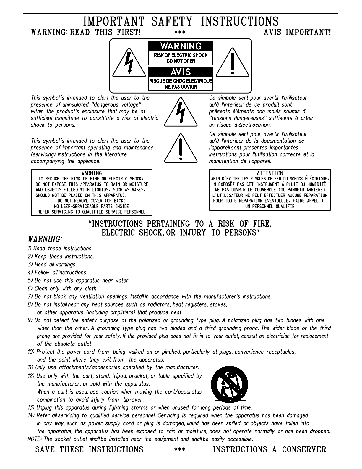
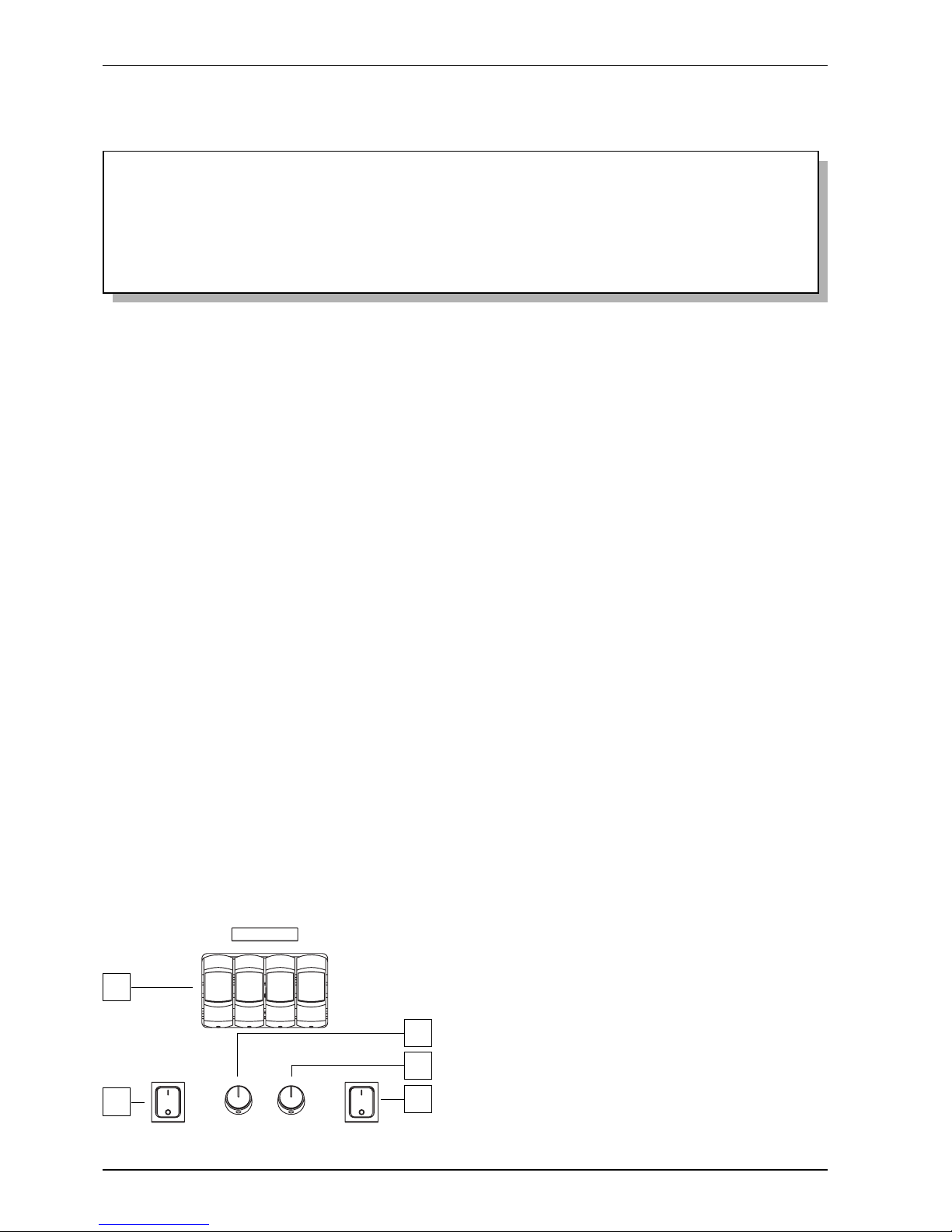
2.1 THE FRONT PANEL
The organ’s front panel above the three manuals contains the stop keys, arranged section by section, used
to activate the registers, and the Crescendo LED bar. Each stop key may be marked with the name of
more than one register, since the associated register may change depending on the organ style selected
with the STYLE parameter on the display (see also chap. 5).
2. CONTROLS AND CONNECTIONS
2 3
1. [PEDAL] section: this section contains the pedal board register stops. The following couplers are
also provided:
o [Great to Pedal]: the stops of the Great will also play on the pedal board.
o [Swell to Pedal]: the stops of the Swell will also play on the pedal board.
o [Choir to Pedal]: the stops of the Choir will also play on the pedal board.
2. [SWELL] section: Swell stops and tremolo.
3. [CRESCENDO] LED bar: displays the steps of the Crescendo currently set with the pedal of the
same name.
4. [GREAT] section: Great stops, tremolo and couplers:
o [Swell to Great]: the stops of the Swell will also play on the Great.
o [Choir to Great]: the stops of the Choir will also play on the Great.
5. [CHOIR] section: contains the stops and tremolo of the Choir and the coupler:
o [Swell to Choir]: the stops of the Swell will also play on the Choir.
4
5
Page 8
6
Viscount Chorale 8
Owner’s Manual
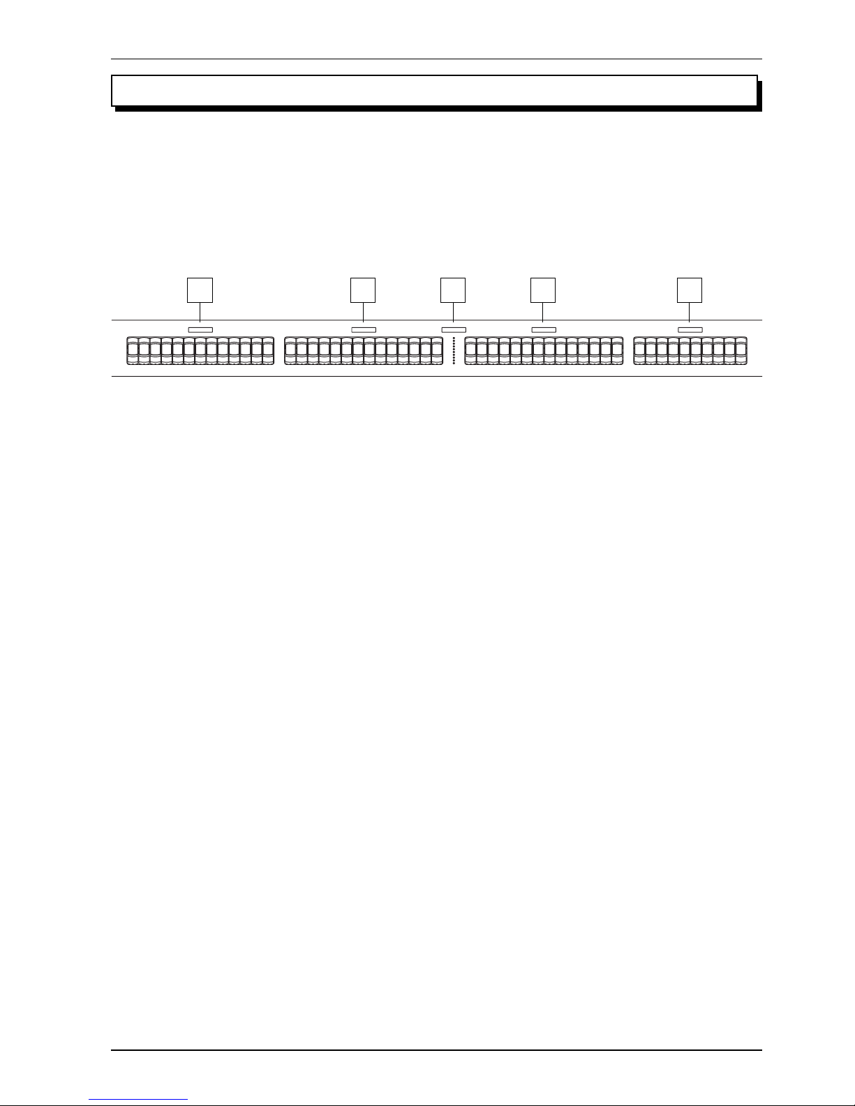
1. General combinations: this section contains the instrument’s general adjustable combinations.
When a combination is recalled, the light of the relative stop illuminates to confirm its activation.
The [NEXT] pistons can also be used to select combinations one by one in an upward direction and
[PREV.] for the same function in a downward direction (combination sequencers).
2. Division combinations: this organ has six adjustable division combinations for Swell (2A), Great
(2B), Choir (2C) and the pedal board (2D). When a combination is recalled, the light of the relative
piston illuminates to confirm its activation.
In division combinations, the user is only able to set the configuration of the section associated to
the selected combination.
There is also a piston marked [HR] (Handle Registers) beside the general and dedicated combinations;
also known as 0, when it is on it automatically memorises the register status. This piston’s main
function is to restore, during use of the combinations, the “hand-made” stop setup created when the
[HR] button was on. Remember that an HR setup is not modified if the stops are switched on and off
by hand when a combination on the same section is selected (i.e. with the HR off).
N.B.
The contents of the HR are not retained when the organ is switched off.
2.2 THE MANUAL SPLITTER CONTROLS
The pistons used to recall the adjustable combinations, Tutti, couplers and other accessory functions are
placed in the areas between the manuals.
HR123456
HR123456
HR123456
HR123456
HR123456
G/P
SW/P
C/P
S
SW/C
SW/G
PREV NEXT
C/G
viscount
MIDI
SW
MIDI
G
MIDI
C
MIDI
P
SWS VOL. MENU
A.P T
C
1 2A
2B 2C2D3
4A4B
4C
5
67 8
9 10
11
12
13
14
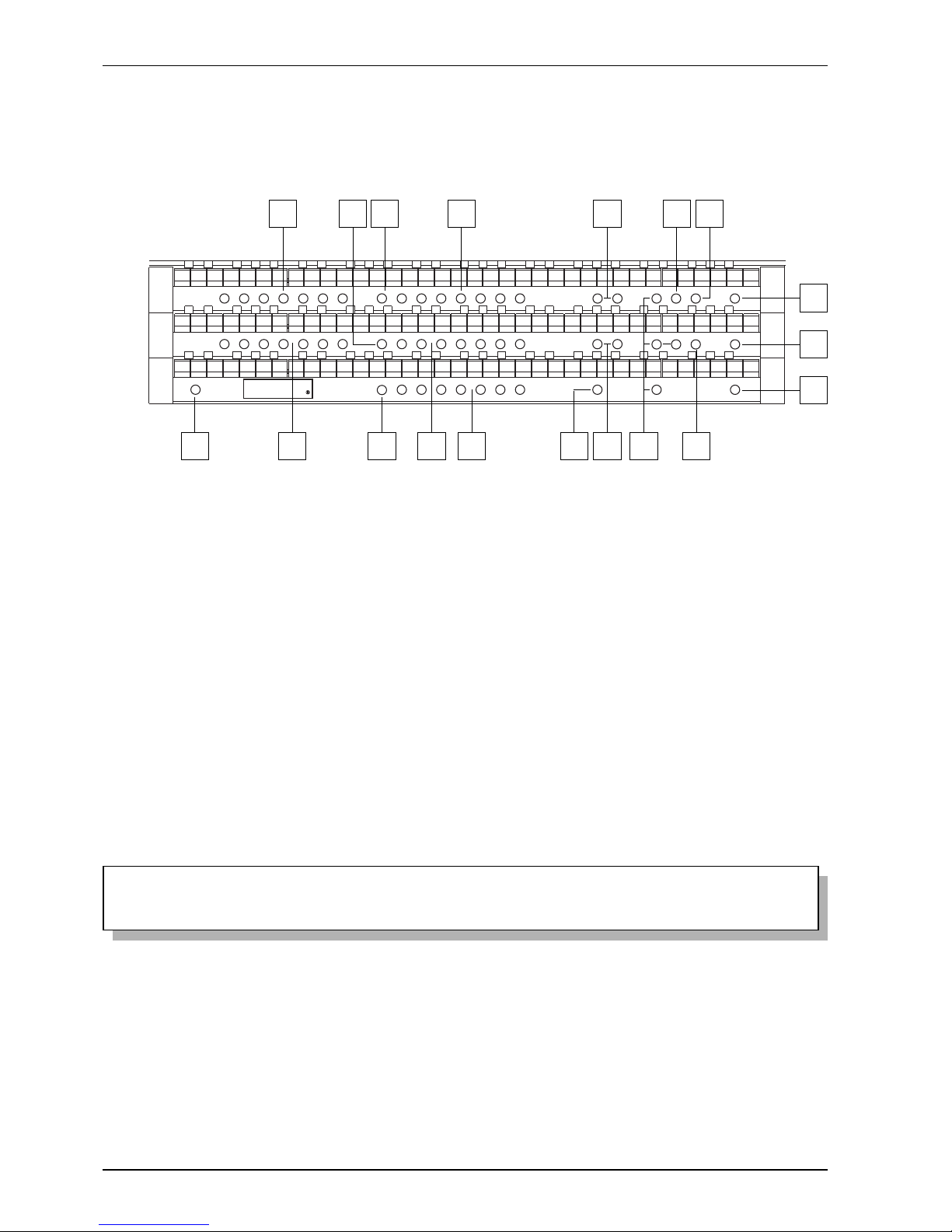
Each combination (including HR and Tutti), whether general or sectional, is able to store:
- the status (on/off) of the stops
- the status of the couplers (enabling saving, see point 7.8)
- the status of the tremolos (even with different modulation depths and speeds, if the specific
SET-UP menu function described in par. 7.8 is activated)
- the style (Organ Style)
- the MIDI controls (point 8) and the Program Changes set using the SEND PROGRAM
CHANGE function (par. 8.2)
Page 9

7
Viscount Chorale 8
Owner’s Manual
The All Swells to Swell pedal and Automatic Pedal can also be saved in the general memories and
HR and in the Tutti only, by activating the specific function, see par. 7.8.
For the fixing combinations procedure, see point 3.
3. [S] piston: “Set” (or fix) function used for fixing combinations. To fix a combination, simply press
the [S] piston, keep it pressed and then press the combination you wish to fix, which may be dedicated,
general or Tutti.
WARNING!
The [S] piston displays the on-off status for enabling of setting of the combinations, the Tutti and the
Crescendo setups, and access to the organ’s setup (LOCK ORGAN function, see point 9.3).
When the light in the piston is on, the functions listed above are enabled; when the light is off, the
organ’s sound setup cannot be modified, and only the parameters shown in the main screen can be
edited.
4. Pistons [P]: these pistons activate the couplings of the manuals with the pedal board, as follows:
o [SW/P] (4A): coupling of the Swell with the pedal board
o [G/P] (4B): coupling of the Great with the pedal board
o [C/P] (4C): coupling of the Choir with the pedal board
5. [NEXT] and [PREV.] stops: general combination sequencers. [NEXT] selects combinations in
ascending order, [PREV.] in descending order.
6. Great couplers: these pistons control the status of the Great couplings, as follows:
o [SW/G]: coupler of the Swell to the Great
o [C/G]: coupler of the Choir to the Great
7. [SW/C] Piston: activates coupling of the Swell to the Choir.
8. [MIDI C], [MIDI G], [MIDI P] and [MIDI SW] pistons: this section contains the pistons used to
activate the transmission of MIDI note codes on the [MIDI OUT] port (in the recess on the left
underneath the Choir) in response to the notes played on the manuals. The LED of each piston displays
the status of transmission on the manual’s MIDI channel as follows:
o Piston illuminated: note code transmission enabled
o Piston off: note code transmission disabled
N.B.
- These pistons activate or deactivate the transmission of MIDI note codes (Note On and Note
Off) only, unlike all the other MIDI messages the organ is able to process, which are always
transmitted regardless of the status of this function.
- These pistons control transmission of MIDI notes only. Reception is always enabled.
Page 10
8
Viscount Chorale 8
Owner’s Manual
ORCHESTRA
POWER EXT. SPK.
MASTER VOL. REVERB VOL.
Pedal
String
Custom
Swell
Celesta
Custom
Great
Chime
Custom
Choir
Harp
Custom
1
3
2
N.B.
When the Enclosed function is activated, the volumes of all manuals are immediately set in relation
to the position of the [SWELL] swell pedal. When the Enclosed function is deactivated, the volume
of the Choir is immediately readjusted in relation to the position of the [CHOIR] swell pedal, while
those of the pedal board and Great are set in accordance with the setting in the VOLUMES function
(see chap. 4).
10. [VOL.] piston: used to display the divisional volumes of each section of the organ.
11. [A.P.] piston: this piston controls the status of the Automatic Pedal function used to play the stops of
the pedal board using the first 32 notes of Great. In this case, the organ’s pedal board is deactivated
and the stops become monophonic, with priority to the lowest note.
12. [MENU] piston: used to display the organ setup functions menu.
13. [T] piston: piston used for switching the Tutti on and off.
The voice composition of the Tutti function is programmable. To set a new configuration, switch on
the stops and couplers of your choice, press [S], keep it pressed and then press the [T] piston or the
[TUTTI] foot piston.
14. [C] piston: Cancel piston, which switches off all the stops, tremolos, couplers and pistons on any
manual divisions active, then resets the general and dedicated HRs.
9. [SWS] piston: pressing this piston activates the “All Swells to Swell pedal” function used to control
the organ’s general volume using the swell pedal [SWELL].
2.3 THE SIDE PANELS
Other organ controls such as the volume controls, reverb adjustment and the graphic display showing all
the instrument’s main setup and adjustment functions are located on the right and left of the manuals, in
easy reach of the organist.
To make use of these controls quicker and easier, all the rotary trimmers and the Orchestra voices are on
the left of the manuals, with the graphic display and the relative control buttons on the right.
LEFT PANEL
4
5
1. [ORCHESTRA] Registers: contains the
registers of the Orchestra voices for the four
sections of the organ.
2. [POWER] Switch: the switch used to switch the
organ on and off.
3. [MASTER VOL.] trimmer: regulates the
organ’s general volume.
Page 11
9
Viscount Chorale 8
Owner’s Manual
4. [REVERB VOL.] trimmer: regulates the level of the reverb digital effects.
5. [EXT.SPK] Switch: on-off switch for loudspeakers (if any) connected to the outputs on the rear
panel, powered by means of the [EXT. +12V DC] socket.
WARNING!
Do not switch the organ on and off in rapid succession. After the instrument is switched off, wait at
least 10 seconds before switching it back on.
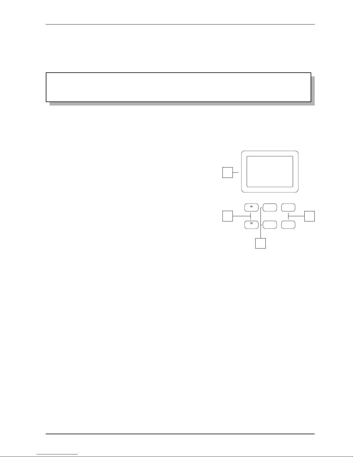
RIGHT PANEL
VALUE
-
+
FIELD
FIELD
ENTER
EXIT
VALUE
1
2
4
3
1. Display: graphic display of 128x64 pixels for display of all
the screens relating to the organ’s functions.
2. [FIELD S] and [FIELD T] buttons: buttons used to move
the cursor around within the display screens. The [FIELD S]
button moves the cursor to the field above (the one currently
selected) while [FIELD T] selects the field below.
3. [VALUE +] and [VALUE -] buttons: buttons for adjusting
parameters. [VALUE +] increases the value, [VALUE -]
decreases it.
4. [EXIT] and [ENTER] buttons: buttons for accessing or
exiting menu screens. [ENTER] is used to enter the menu or
function shown on the display or confirm any prompts from
the system. [EXIT] is used to exit the screen on the display
and return to the previous one, or abort any prompts from the
system.
Page 12
10
Viscount Chorale 8
Owner’s Manual
PLENUM
REED
TUTTI
GT/PD
SW/PD
CHR/PD
SW/GT
CHR/GT
SW/CHR
CHOIR SWELL CRESCENDO
2.4 PEDAL BOARD CONTROLS
The bottom part of the organ, above the pedal board, contains the swell pedals and a number of foot
pistons for controlling the couplers, the Plenum and Reeds functions and the Tutti.
1 2 5
N.B.
The display volume controls which can be displayed by pressing the [VOL.] button allow balancing
of the sections; once you have set the levels best suited to your taste and the sound balance you
require, they will not require frequent adjustment.
The swell pedals, on the other hand, allow continuous control of the volumes, enabling you to obtain
all the dynamic effects you wish. Apart from regulating the volume, the swell pedals also simulate
the variation in timbre of the stops which would occur in the swell boxes of pipe organs.
1. Coupler pistons: these pistons activate the organ couplings described in par. 2.1 (point 1 e 2).
2. [CHOIR] Swell Pedal: swell pedal used to regulate the volume of the Choir.
3. [SWELL] Swell Pedal: this swell pedal is used to regulate the volume of the Swell.
4. [CRESCENDO] pedal: you can use this pedal to select the Crescendo steps which activate a preset series
of stops. The step currently selected is displayed by the [CRESCENDO] LED bar on the central panel (see
also point 2.1, subsection 3).
Each Crescendo step is programmable. To do this, use the [CRESCENDO] pedal to select the step you
require, switch on the voices and couplers of your choice, press [S], keep it pressed and then press the
general memories [HR] button.
5. [PLENUM] piston: piston which activates the Plenum, which will be added to the existing sound setup.
6. [REEDS] piston: piston which activates the reed registers, which will be added to the existing sound setup.
The sound compositions of the Plenum and Reed functions are programmable. To save a new configuration,
switch on the registers of your choice, press the [S] piston, keep it pressed and then press the [PLENUM]
or [REEDS] piston.
7. [TUTTI] foot piston: piston used to activate the Tutti. For a more detailed description, refer to point 13 of
section 2.2.
8. Sustain switch pedal: Sustain pedal to be used with the Orchestra voices.
3 4
8
6 7
Page 13
11
Viscount Chorale 8
Owner’s Manual
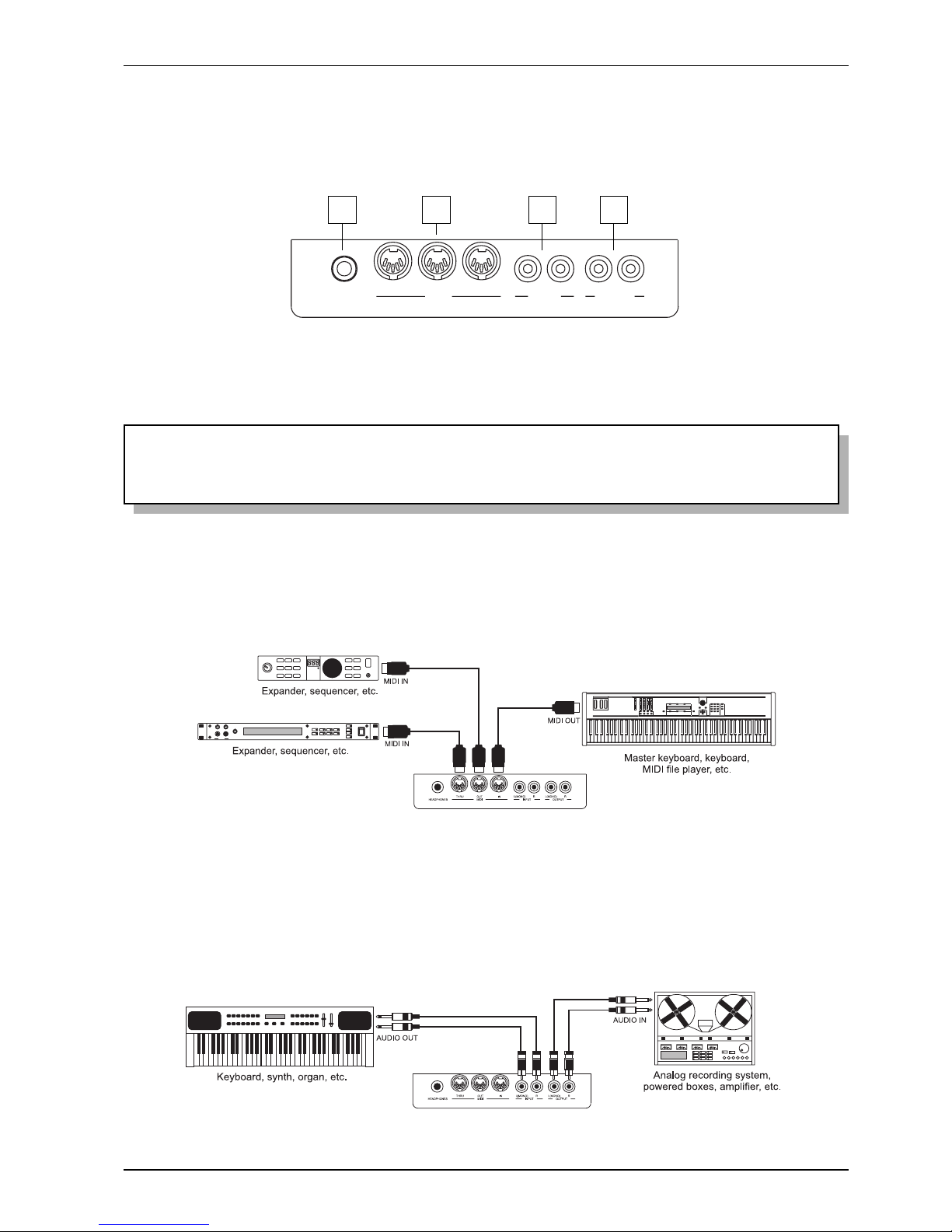
2.5 THE CONNECTIONS UNDERNEATH THE MANUALS
In the left of the organ, under the surface which contains the manuals and side panels, there is a small
recess containing various connectors for connecting the organ to remote sound and MIDI devices.
THRU OUT
MIDI
IN
L(MONO)
INPUT
R L(MONO)
OUTPUT
R
HEADPHONES
1 2 3 4
1. [HEADPHONES] connector: Jack socket to which a headphone set can be connected. With headphones
connected, the organ’s internal amplification is cut off.
2. [MIDI] connectors: five-pin DIN connectors for connection of instruments with MIDI interface. The [IN]
connector allows receipt of MIDI data generated by remote MIDI sources, the [OUT] connector transmits
the MIDI messages generated by the Chorale 8, and the [THRU] connector transmits the MIDI data
exactly as received at the [IN] connector.
3. [INPUT] connectors: RCA line inputs which allow other instruments to be played using the organ’s internal
amplification. If the source is monophonic use the L(MONO) connector only.
4. [OUTPUT] connectors: RCA line outputs for the unamplified signal, for connection of optional
amplified speakers, remote amplification systems or recording systems. To use a monophonic signal,
connect to the [L/(MONO)] connector only.
N.B.
To obtain the best results from the [HEADPHONES] output, phones with impedance of at least 16
Ω
should be used.
Page 14
12
Viscount Chorale 8
Owner’s Manual
-
+
EXT.
+12V DC
300 mA
L(+R) R L(+R) R RL
OPTIONAL
SPEAKER OUT 8
AUX OUT 2AUX OUT 1
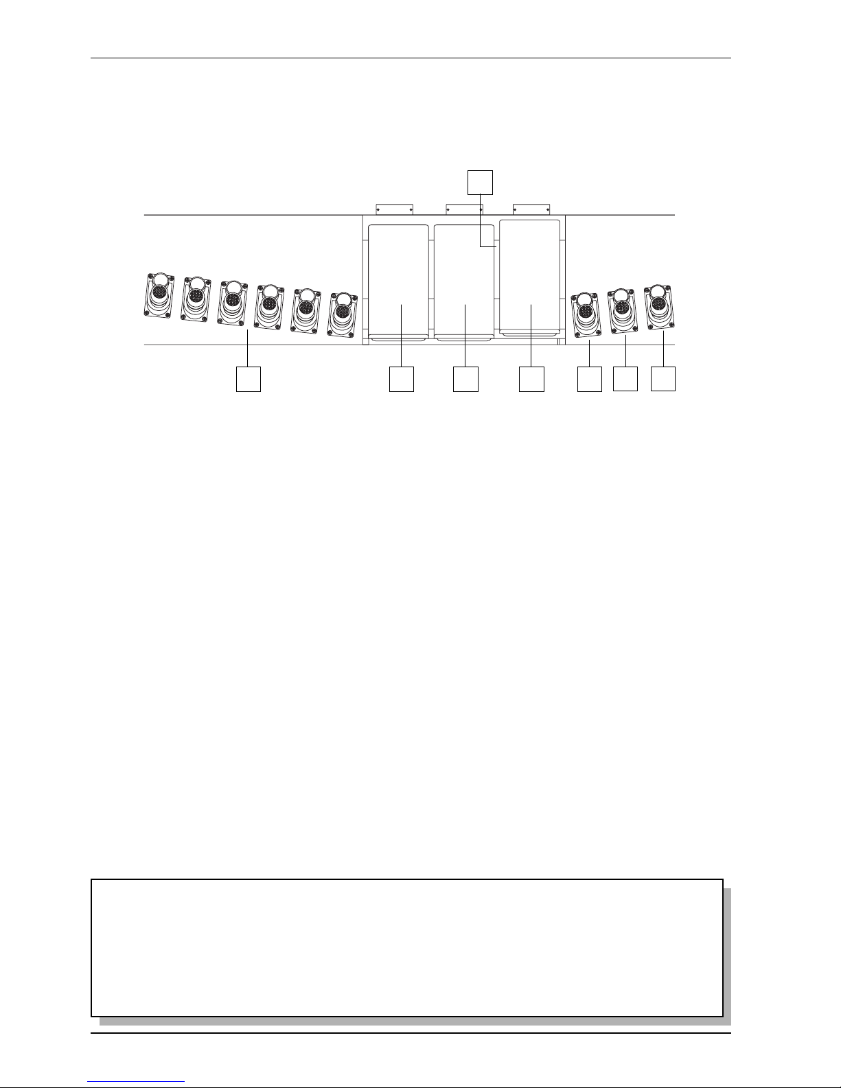
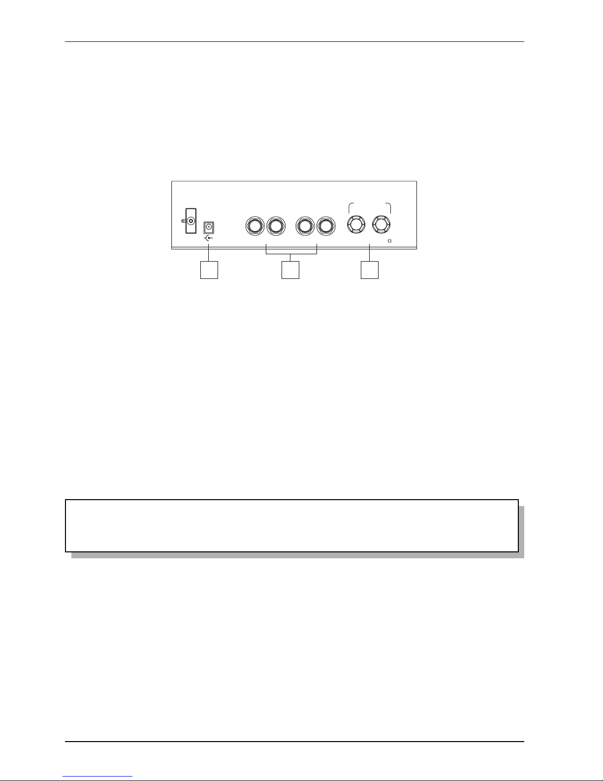
2.6 THE CONNECTIONS ON THE REAR PANEL
In the bottom of the rear panel there are two more pairs of line audio outputs, an optional amplified stereo
output, and the power supply socket for the connected loudspeakers.
The main difference between these outputs and the ones in the recess underneath the manuals is that the
latter contain the signal generated by the organ, while on the rear connectors, the signals of the individual
manuals and pedal board are routed to and adjusted on the individual outputs in accordance with the
relative settings on the display (for more information see points 7.3, 7.4 and 7.5).
1
1. [EXT. +12V DC] connectors: these sockets can be used to obtain the +12V DC voltage needed to supply
the VISCOUNT speakers connected to the [AUX OUT] outputs
2. [AUX OUT 1] and [AUX OUT 2] connectors: Jack line outputs carrying the organ signal in
accordance with the routing set by means of the function on display. With the Factory Settings active,
the signals are distributed as follows:
- [AUX OUT 1]: General signal
- [AUX OUT 2]: Reverb only
3. [SPEAKER OUT] connectors: amplified stereo output to which a pair of passive loudspeakers can
be connected. In Factory Setting mode, the amplified general organ signal can be obtained from these
outputs. The optional internal amplifier must be installed to allow use of these outputs. Contact your
dealer for more information.
N.B.
For installation, connection and setup of the internal amplifier refer to the installation guide in the
optional’s packaging.
2 3
Page 15
13
Viscount Chorale 8
Owner’s Manual
3. MAIN CONTROL UNIT
As described in the previous section, the right-hand panel beside the manuals contains the main control unit for all
the Choral 8’s internal functions.
The organ features a large set of control functions allowing the user to customise the instrument in the
most suitable way, adapting it to his or her own requirements. These are not mere general settings, but
setup functions that configure every part of the organ: for the sound setup, for example, the user can
select the instrument’s musical style, or change the registers assigned to the stops and then regulate their
individual volumes.
The levels, equalisation and channel routing of the remote outputs can also be adjusted.
The organ also allows complete, unrestricted configuration of the MIDI interface, as well as the familiar
settings of the tremolo and reverb effects, the manuals and the pedal board, the internal graphic equalizer
and the piston functions.
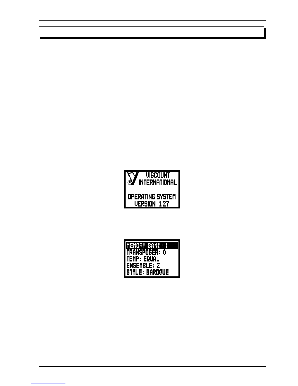
3.1 SWITCHING ON AND MAIN VIDEO PAGE
When the organ is switched on using the [POWER] switch on the left-hand panel, the instrument becomes
operational after a few seconds, during which time all the amplification circuits are activated and the
internal systems are configured. While this is taking place, the display shows the introductory screen:
on which the release of the firmware installed on the instrument can always be checked.
After the switch-on procedure is complete, the main video page will be displayed:
containing the following display fields:
o MEMORY BANK: this parameter can be used to select one of the eight memory banks for saving
the general and/or specific combinations.
Therefore, as well as providing a total of 48 general and 192 dedicated combinations, this function is
especially useful if the instrument is used by more than one organist, since each of them will be able
to save his or her own programming settings in a different Memory Bank.
o TRANSPOSER: key transposer with a range of +5 / -6 semitones (adjustments in steps of one
semitone).
Page 16

14
Viscount Chorale 8
Owner’s Manual
o TEMP (Temperament): this parameter allows the selection of a series of historic temperaments of different
eras and national origins. You can choose from EQUAL, a temperament with perfect tuning, or the classical
KIRNBERGER, WERCKMEISTER, PYTHAGOREAN, MEANTONE and VALLOTTI
temperaments.
o ENSEMBLE: this parameter can be used to set six levels of natural tiny differences in pitch between
one organ pipe and another, in order to simulate the tuning errors that occur in the organ’s pipes due
to wear over time and variations in temperature. If you wish to use the registers perfectly tuned, select
the – value.
o STYLE: selection of the organ style required. For further information refer to chap. 5.
HOW TO MOVE AROUND INSIDE THE SCREENS
The screen cursor is in the form of the field displayed in reverse; in the screen shown above, for example,
the cursor is located on the MEMORY BANK parameter.
As explained in paragraph 2.3, to move the cursor use the [FIELD S] and [FIELD T] buttons.
[FIELD S] moves the cursor to the field above, [FIELD T] locates it on the one below.
If a menu consists of more than one screen, an arrow symbol indicating that previous and/or subsequent
pages are available will appear in the top right-hand corner.
there are pages after the one currently displayed
there are pages before the one currently displayed
there are pages before and after the one currently displayed
To access a submenu or a function, press the [ENTER] key; to exit the current screen use the [EXIT] button.
To adjust parameters or select the various settings / options, use the [VALUE +] and [VALUE -] buttons.
A BRIEF NOTE ON TEMPERAMENTS
In the “natural” tuning system, based on the acoustic phenomenon of harmonic sounds, two important musical intervals, the
major third and the perfect fifth, cannot be made to coexist in the “pure” state (i.e. beat-free). Therefore, over the centuries a
variety of compromise solutions known as TEMPERAMENTS have been invented and realised. These give priority to one or
the other interval by modifying them in various ways.
In the ancient world and the Middle Ages, until the last few decades of the 17th Century, the “Pythagorean” tuning system, in
which the fifths were retained perfectly pure, was in use. The resulting major third was particularly unattractive in sound, and
was therefore treated as a dissonance.
However, the music of the time was mainly monodic, and the early forms of vocal and instrumental polyphony made a great
deal of use of the interval of a fifth. With the early Renaissance, and the start of the great flowering of vocal polyphony, the
interval of a major third gradually came to be heard as consonant and not dissonant. The instruments with fixed tuning, such
as the organ and harpsichord, gradually adapted to this situation by adopting a system of temperament known as “Meantone”,
which gave the major third priority over the fifth. This temperament is particularly important because it was the temperament
in normal use in Europe in the 16th and 17th Centuries, until the early 18th Century. Here are the six temperaments available on
the Chorale 8, first and foremost the MEANTONE.
Page 17
15
Viscount Chorale 8
Owner’s Manual
MEANTONE
- 8 pure major thirds: E flat - G / B flat - D / F - A / C - E / G - B / D - F # / A - C# / E - G.
- 4 unusable major thirds (diminished fourths): B - D# / F# - A# / C# - E# / A flat - C.
- 1 fifth known as the “wolf” (very dissonant extended fifth): A flat - E flat.
- Highly irregular chromatic scale (meaning that chromatic compositions are given a very distinctive voice)
- Keys usable with this temperament: C maj. / D maj. / G maj. / A maj. / B flat maj. and the relative minors.
The temperaments which follow allow all the major and minor keys to be used, although those with the most alterations have
a highly distinctive voice, in contrast with the modern equal temperament.
WERCKMEISTER
This temperament, invented by the organist and musical theorist Andreas Werckmeister, is recommended for performing the
German musical repertoire of the late 1600s.
KIRNBERGER
This temperament, developed by Johann Philipp Kirnberger, pupil of J.S. Bach, is also suitable for playing the German
baroque composers and the works of Bach.
PYTHAGOREAN
In this temperament, all the fifths are natural except for the “wolf” fifth, in the interval A flat - E flat, which is greatly
diminished.
It dates from the Middle Ages up to the 15th century, and can therefore be used for compositions of that period.
VALLOTTI
This Italian temperament invented by Francescantonio Vallotti was later taken up in England by Thomas Young. It can be
used effectively for the Italian 18th Century repertoire, and also for the English repertoire of the same period.
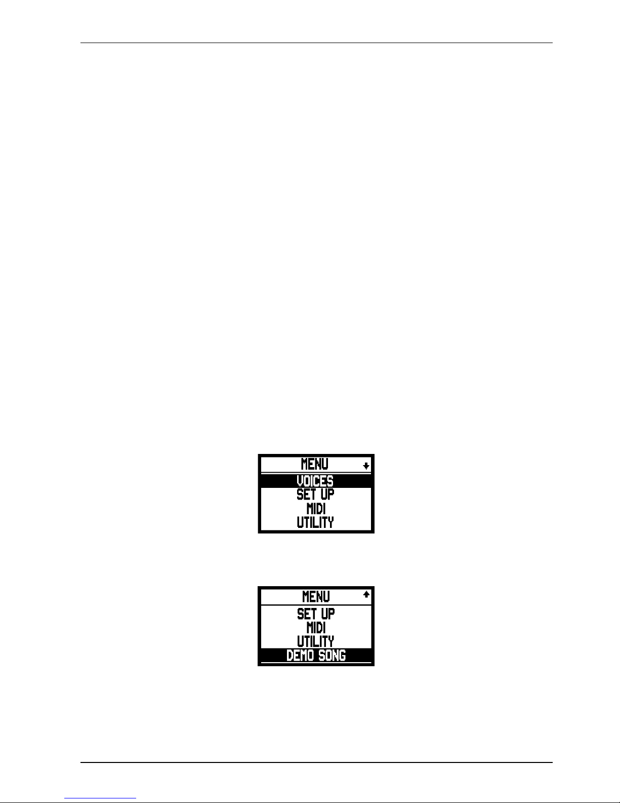
3.2 AN INTRODUCTION TO THE INSTRUMENT’S SETUP FUNCTIONS
Pressing the [MENU] piston in the Swell panel accesses the menu containing all the organ’s setup functions.
The first video page displayed is as follows:
scroll the cursor downwards using the [FIELD T] button to display the second part of the menu:
The display options are:
o VOICES: setup functions for all the organ’s voices, such as loading of alternative voices and volume
adjustment.
Page 18

16
Viscount Chorale 8
Owner’s Manual
o SETUP: this submenu contains all the organ’s general settings, such as adjustment of the tremolos and
equalisers, selection of the type of reverb, adjustment of the real output signals, and setup of the manuals and
the pistons on the section control boards.
o MIDI: setup of the organ’s MIDI interface.
o UTILITY: utility functions such as adjustment of the instrument’s fine tuning, display contrast,
copies the styles, recall of the Factory Settings and controls access to the modification functions.
o DEMO SONG: collection of a number of demonstration tracks.
To access the submenu of your choice, select the relative display field using the [FIELD S] and [FIELD
T] buttons and press [ENTER]. Use the [EXIT] button to return to the main video page.
For a clearer view of the various submenus, the table below summarises the way in which all the organ’s
functions are organised.
VOICES
Voices Volume
Pedal Voices Volume
MENU SETTIN
G
Choir Voices Volume
Great Voices Volume
Swell Voices Volume
Alternative Voices
Pedal Alternative Voices
Choir VoicesAlternative
Great Alternative Voices
Swell Alternative Voices
SETUP
Tremolo
Tremolo setting
Reverberation
Reverberation Type
Equalizer
Internal Equalizer setting
Out1 & 2 Equalizer setting
Speaker Out Equalizer setting (optional)
External Out Router
External Out Router setting
External Out Volume
External Out Volume setting
Keyboard Setting
Choir/Great Keyboards Inversion setting
Key Velocity setting
Pistons Setting
Great/Pedal Piston Combine setting
Prev./Next Pistons Action setting
Function Stored into Piston
Tremulant Depth and Speed setting
SWS and A.P. setting
Couplers setting
MIDI
TX/RX Channel
Pedal channel setting
Choir channel setting
Great channel setting
Swell channel setting
Send Program Change
Pedal PG setting
Choir PG setting
Great PG setting
Swell PG setting
TX/RX Filter
Control Change filter setting
Program Change filter settin
g
Sys-Ex filter setting
Real-Time filter setting
UTILITY
Tuning setting
LCD contrast setting
Style Copy function
Factory Setting
Lock Organ setting
DEMO
Demo song selection
Page 19

17
Viscount Chorale 8
Owner’s Manual
5. ORGAN STYLE
One important feature of the Chorale 8 series is the availability of four different organ styles, Baroque, French,
English and American which allow you to set the sound configuration perfectly suited to the literature you intend
to perform
Since they have been programmed as appropriate to the different schools of organ building, these styles
cannot be modified by the user. There are 4 additional User styles, which can be modified as required.
Remember that the stop switches on the front panel can contain more than one register each. This is because
when different styles are selected, the registers assigned to the various stops may change. The names of the
registers marked on the stops are the ones which will be recalled by the preset styles; however, the User styles
may recall registers the names of which are not screen-printed on the stops if the user programmes them to do
this.
Each style automatically saves the modifications made to the sound setup using the voice replacement
functions and voice volume adjustments. This means that each style can be modified and customised to
personal taste, making the organ extremely flexible.
When a specific basic setup is required during programming, the instrument also allows a style (which
may be a fixed style) to be copied into another User style using the STYLE COPY function described in
point 9.1.
The video page used to select the organ style required is displayed a few moments after the organ is
switched on. The style can be recalled using the STYLE parameter.
4. REGULATING THE SECTION VOLUMES
Pressing the [VOL.] piston on the Swell panel displays the section volumes video page:
Use the [FIELD S] and [FIELD T] buttons to move the cursor to the relevant section and [VALUE +] and
[VALUE -] to adjust the volume as required. To confirm the changes and exit the video page, press the [EXIT]
button.
Using the [VALUE +] and [VALUE -] buttons you can select the desired style.
Page 20

18
Viscount Chorale 8
Owner’s Manual
As described in the instruction to this section, it is important to remember that the Organ Styles save the status of
the following functions:
- ALTERNATIVE VOICE (voices assigned to each stop)
- VOICE VOLUME (volumes of the voices)
- REVERBERATION (type of reverb effect)
- INTERNAL EQUALIZER (equalizer for the internal amplification system)
- EXTERNAL EQUALIZER (equalizzatore per le uscite audio posteriori)
The functions described above can only be modified when a User style has been selected. Since the
Baroque, French, English and American styles cannot be edited, if the user attempts to modify these
functions the display will show:
6. REPLACING VOICES AND REGULATING VOICE VOLUMES
One important new feature of the Chorale 8 series is the capability for replacing the voices initially associated to
the front panel stops with other voices already provided in the organ’s internal memory.
In practice, this gives quick, easy voice replacement, which however enables you to set your organ’s
entire sound setup exactly as you wish and at any time, with considerable advantages for the customisation
of the instrument, and for its use by more than one organist (each of them will be able to have their own
set of voices). The register setup can be further adjusted to individual requirements through regulation of
the volume of each individual voice.
All voice management functions can be recalled by selecting the VOICES after the [MENU] piston is
pressed. The video page displayed is as follows:
containing the following functions:
o VOICES VOLUME: regulates the volume of the voices.
o ALTERNATIVE VOICE: used to replace voices.
To display the function required, select the relative display field using the [FIELD S] and [FIELD T]
buttons and press [ENTER]. Use the [EXIT] button to return to the MENU video page.
Page 21

19
Viscount Chorale 8
Owner’s Manual
containing the organ’s four sections. Then select the division where the voice for which you wish to adjust the
volume is located or press for some seconds its tab insert (on the front panel):
6.1 REGULATING THE VOICE VOLUMES
The VOICES VOLUME function allows you to adjust the volume of each individual voice in a range
from -9 dB to +9 dB. Each modification is saved immediately and is audible in real time, making it easier
for the user to obtain the setting required. You must also remember that the voice volumes are saved by
the organ styles, so when a style change is made, apart from possible replacements of the stop voices, the
volumes will also be reconfigured to suit the selected style.
However, changes made to the volumes are not lost when different styles are recalled and they are retained
in the memory within the style.
To recall this function, select the VOICES VOLUME option from the SETTING MENU; the display will
show:
In the first example the display will show the first 4 voices of each section. In case this procedure is done through
the tab insert il will immediately show the volume of the voice. In both cases, use buttons [FIELD S] and
[FIELD T] for having on the display the volume of another voice.
To regulate the volume, use the [VALUE +] and [VALUE -] buttons.
The new value is rendered audible immediately and saved; press [EXIT] to return to the previous screen.
IMPORTANT NOTES
- The volumes of the individual voices are automatically saved in the current Organ Style (see
also section 5). This means that when another style is recalled, the volumes will be reset to the
values described in the last style recalled. When the style in which the voice volumes were
changed is reloaded, the volumes will be reset to the latest adjustments.
- To restore the original volumes of all the styles, recall the FACTORY SETTING function described
in point 9.2.
Page 22

20
Viscount Chorale 8
Owner’s Manual
6.2 REPLACING VOICES
As described at the start of this section, the Chorale 8 has an interesting, useful voice replacement function.
The organ has a vast internal library of voices, comprising various variations on the original voices.
To recall this function, select the ALTERNATIVE VOICE option from the VOICES submenu; the display
will show the first screen:
in which you have to select the section of the organ containing the stop of the voice to be replaced, or press the
stop itself on the front panel (as if to switch it on). In the first case the display shows the first four voices in the
section selected.
while if you hold pressed the stop the display immediately shows the screen shown below.
Now use the [FIELD S] and [FIELD T] buttons to select the voice you wish to replace. After locating
the cursor on the voice concerned, press [ENTER].
The top of the display contains information concerning the voice you are about to replace, while the central part
of the screen shows the possible replacement registers for that specific stop.
Here again, you can use the [FIELD S] and [FIELD T] buttons to scroll through all the replacement
voices, which are rendered audible immediately for quicker programming by just moving the cursor over
the fields of the voices displayed.
Once you have found the voice you require, press [ENTER]:
Page 23

21
Viscount Chorale 8
Owner’s Manual
the system now provides information about the voice to be replaced (in the top of the screen) and the new voice
(in the middle), and a prompt for confirmation to proceed, since the new register has not yet been definitively
loaded, but has simply been rendered audible for evaluation. As the display shows, press [ENTER] to confirm
the replacement or [EXIT] to abort.
If you now go ahead with the operation, the system will definitively replace the old voice and give
confirmation with the following screen:
IMPORTANT NOTES
- The voices for loaded for each stop are automatically saved in the current Organ Style (see also
section 5). This means that when another style is recalled, the voices will be reset to the last style
recalled. When the style in which the voices were changed is reloaded, the voices will be reset to
the latest adjustments.
- When a replacement voice is loaded, it will be assigned the volume value set for the voice
present on the relative stop before the change was made.
- To restore the original voices of all styles, recall the FACTORY SETTING function described in
point 9.2.
Page 24

22
Viscount Chorale 8
Owner’s Manual
7. INSTRUMENT GENERAL SETTINGS
All the organ’s general setup functions, i.e. the settings not strictly linked to the voices or the MIDI interface, are
found in the SET UP submenu recalled by selecting the field of the same name on the display in the MENU.
The first video page displayed is as follows:
The following is a short description of the various settings:
o TREMOLO: setting of the Tremolos for each manual.
o REVERBERATION: selection of the type of reverb required.
o EQUALIZER: for the equalizers adjustment.
o EXT. OUT ROUTER: routing of the manuals and pedal board on the audio outputs [AUX OUT 1],
[AUX OUT 2] and [SPEAKER OUT] (optional).
o EXT. OUT VOLUME: regulates the volume of the audio outputs.
o KEYBOARD SETTING: manual operation settings.
o PISTONS SETTING: operation of the pistons on the section control boards.
o FUNCTION STORED: combination fixing settings.
As usual, use the [FIELD S] and [FIELD T] buttons to move the cursor and [ENTER] to display the
screens of the functions required. Press [EXIT] to return to the MENU.
Since there are a large number of settings, the menu is displayed on two screens. Scroll the cursor downwards to
display the other functions in the list:
Page 25

23
Viscount Chorale 8
Owner’s Manual
containing the current values of the DEPTH (modulation depth) and SPEED (modulation speed) parameters of
the tremulants of the three manuals.
Then press [EXIT] to return to display of the SET UP menu and save the new settings.
N.B.
The Depth and Speed parameters can be saved with different values in each general and specific
combination and in the Tutti. To do this, saving must be enabled using the Function Stored function
described in point 7.9.
7.2 SELECTING THE TYPE OF REVERB
Reverberation is the result of a series of sound reflections propagated inside an enclosed environment.
The order and value of each reflection depend to a very great extent on an a large number of factors which
come into play within any one room, such as the size of the room in which the phenomenon takes place,
the nature of the materials of which it is made and the objects it contains, the listener’s position, etc.
The digital signal processors incorporated in the Chorale 8 organs are able to artificially re-create the complex
reverberations that naturally occur in the types of building where pipe organs are normally installed, and
thus generate the right reverb effect to complete the instruments’ excellent timbre qualities.
The purpose of the REVERBERATION TYPE function in the SET UP menu is to allow you to select the
type of reverb effect, ranging from a large church with strong reverb and many sound reflections to a
small room with short, muffled reverb.
You may use this function to select eight different types of reverb effect.
You can then use the [REVERB] trimmer in the left-hand control panel to regulate the level of reverb
effect required.
7.1 SETTING THE TREMOLO
In pipe organs, it is of fundamental importance for the air pressure to be constant in order to obtain an
even, “sustained” sound. However, a number of mechanical devices were introduced to generate a number
of periodic variations of varying intensity in the air flow.
These variations produced a “tremulant” effect on the sound, which made a number of solo stops (such as
the Vox Humana) more pleasant on the ear, and gave added expression to the reed stops.
This effect can be enabled and disabled using the [TREMOLO] stops.
The TREMOLO function can be used to set the speed and modulation depth of the tremolos for each
manual.
After the TREMOLO field is selected in the SET UP menu, the display will show the video page:
Page 26

24
Viscount Chorale 8
Owner’s Manual
To select the reverb required, select the REVERBERATION field in the SET UP menu and press [ENTER]:
The types available are:
o CATHEDRAL: reverb typical of a cathedral
o BASILICA: reverb typical of a basilica
o GOTHIC CHURCH: reverb typical of a Gothic church
o BAROQUE CHURCH: reverb typical of a Baroque church
o ROMANIC CHURCH: reverb typical of a Romanesque church
o MODERN CHURCH: reverb typical of a modern church
o PARISH: reverb typical of a church hall
o CAPPELLA: reverb typical of a chapel
Use the [VALUE +] and [VALUE -] buttons to select the type of reverb and press [EXIT] to save the
selection and return to display of the SET UP menu.
N.B.
- The organ’s internal reverb also affects the input signals reaching the [INPUT] connectors
underneath the manuals.
- The Organ Styles save the type of reverb. This means that organ styles with different types
of reverb may be available, and that when a different style is recalled the reverb may be
modified.
Page 27
25
Viscount Chorale 8
Owner’s Manual
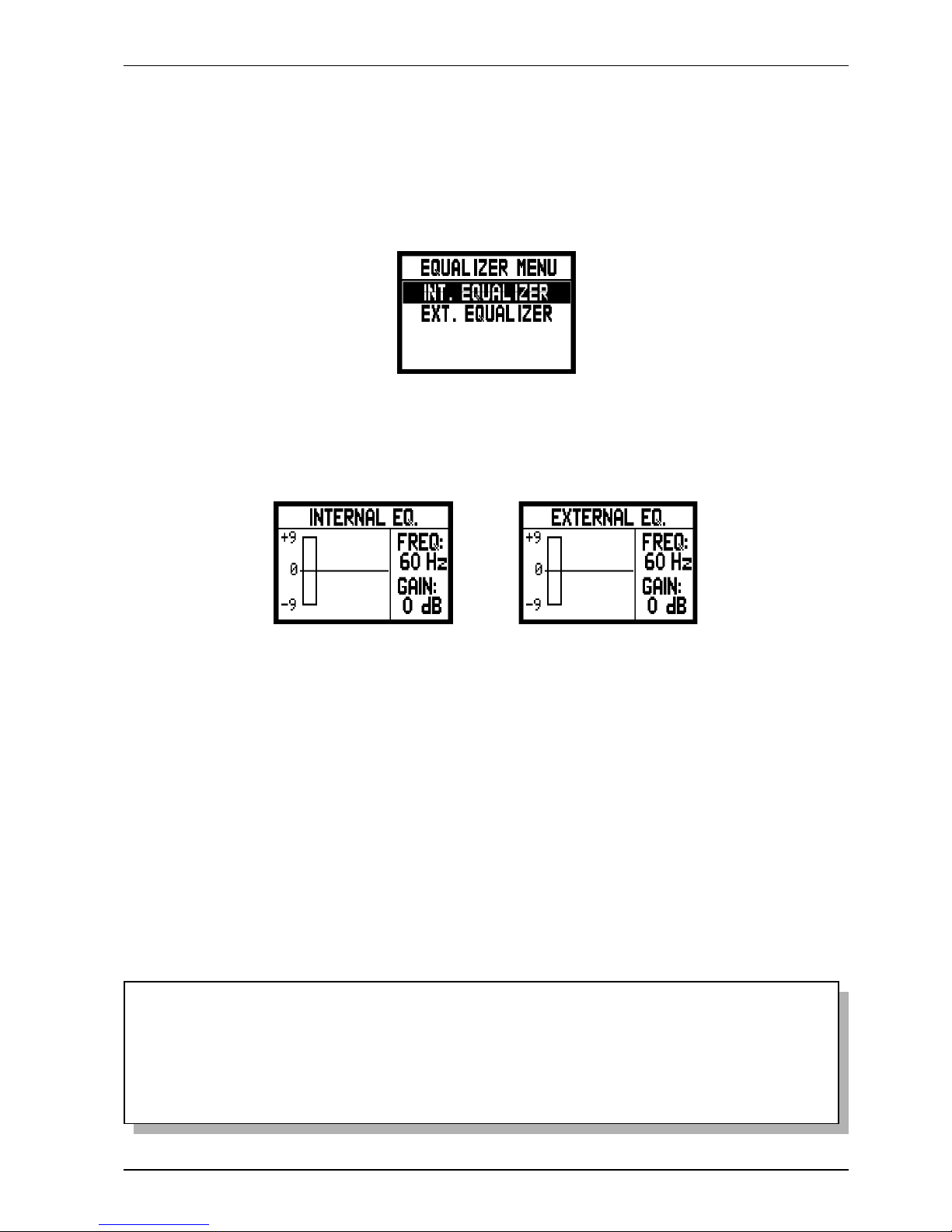
7.3 EQUALIZERS ADJUSTMENT
Your Chorale 8 organ is equipped with two 5-band graphic equalizers for the sound control.
There is one equalizer for controlling the signal to the internal loudspeakers. A second equaliser is assigned
to the signals sent to the [AUX OUT 1] and [AUX OUT 2] audio outputs, and a third to the [SPEAKER
OUT] (optional) amplified output. In order to display these adjustments, select EQUALIZER and press
[ENTER].
o INT. EQUALIZER: this displays the internal equalizer
o EXT. EQUALIZER: this displays the audio outputs equalizer
As you can see the following parameters appear on the right of the screen:
o FREQ: central trigger frequency.
o GAIN: gain of the signals with frequencies close to that stated in the FREQ parameter.
The [FIELD S] e [FIELD T] buttons can be used to select the trigger frequency; then use the [VALUE
+] and [VALUE -] buttons to regulate the attenuation (negative values) or enhancement (positive values)
of the signal in a range of +/- 9 dB.
A graphic indication of the equalizer is also displayed on the right of the screen, in real time.
Here again, after making the settings you require, press the [EXIT] button to save the modifications and
return to display of the SET UP menu.
NOTES
- The external equalizer settings also affect the signals supplied to the RCA [OUTPUT] outputs
in the recess underneath the manuals.
- The equalizers adjustment settings are also stored in the Organ Style. This means that organ
styles with different types of external equalization may be available, and that when a different
style is recalled the equalizer may be modified.
Page 28

26
Viscount Chorale 8
Owner’s Manual
7.4 SIGNAL ROUTING ON THE AUDIO OUTPUTS
Another useful setting available on the Chorale 8 is the option of sending the signals of the individual manuals and
pedal board to one audio output or both. This allows you to simulate location of the windchests in different
positions by allocating the external speakers as required.
To display the setting video page, select the EXT. OUT ROUTER field in the SET UP menu:
The screen shows the two audio outputs, OUT1 ([AUX OUT 1]) and OUT2 ([AUX OUT 2]). You can set the
signal source section for each output, as follows:
o PEDAL+GREAT
o GREAT
o SWELL
o PEDAL + GREAT + CHOIR
o PEDAL + GREAT + SWELL
o CHOIR + SWELL
o GENERAL (OUT1 only)
o REVERB ONLY (OUT2 only)
As usual, use the [FIELD S] and [FIELD T] buttons to move the cursor and [VALUE +] and
[VALUE -] to adjust the values.
To conclude, press [EXIT] to save the new settings and return to the SET UP menu.
7.5 REGULATING THE AUDIO OUTPUT VOLUMES
Another setting function available for the audio outputs is adjustment of the volumes of the individual
outputs. To make the settings, select the EXT. OUT VOLUME field in the SETUP menu; the display
shows the screen:
containing the following parameters:
o OUT 1: volume of output [AUX OUT 1].
o OUT 2: volume of output [AUX OUT 2].
Page 29

27
Viscount Chorale 8
Owner’s Manual
All the levels can be set in a range of values from 1 to 32, with the following relative dB:
- 32: 0 dB
- 20: -12 dB
- 16: -16 dB
- 10: -22 dB
- 1: -31 dB
Naturally, intermediate signal level values will be obtained when values between these settings are shown
on the display.
NOTE
The rear output volume settings also affect the signals supplied to the RCA [OUTPUT] outputs in
the recess underneath the manuals.
7.6 GENERAL MANUAL SETTINGS
The KEYBOARD SETTING function, recalled using the option of the same name in the SET UP menu,
contains two different parameter relating to operation of the organ manuals. The video page displayed is
as follows:
containing the following display options:
o CH/GT INVERS.: inversion of the manuals, so that the Choir registers are played with the Great and
vice-versa.
o KEY VELOCITY: activates the manual key dynamics. When this function is active, you can play
the Orchestral voices and transmit the MIDI notes in response to the speed at which the manual keys
are pressed.
If the function is turned off, the notes are always played with fixed dynamic equal to the MIDI value
100.
To activate the two functions, use the [VALUE +] and [VALUE -] buttons to select the value YES, or
select NO to deactivate them. Use the [FIELD S] and [FIELD T] buttons to move the cursor and [EXIT] to
save the new settings and return to the SET UP menu.
Page 30

28
Viscount Chorale 8
Owner’s Manual
In this first screen you may activate or deactivate the Piston Combine function which allows the combinations of
the Great to be “coupled” to those of the pedal board. This means that when a Great combination is recalled, the
same combination will also be automatically activated for the pedal board.
To activate the function, use the [VALUE +] and [VALUE -] buttons to select the value YES, or select
NO to deactivate it.
Now press the [FIELD T] button to display the second PISTONS SETTING function, relating to the
function of the [PREV.] and [NEXT] pistons:
7.7 PISTON SETTINGS
The Chorale 8 setup procedure allows you to set the function of sector combination pistons and the pistons used
for sequential recall of the general combinations [PREV.] and [NEXT].
To set these functions, select the PISTONS SETTINGS field in the SET UP menu; the display shows the
screen:
If GENERAL MEMORY is selected the pistons operate like ordinary sequencers, recalling the individual
general combinations in ascending or descending order.
If MEMORY BANK is set, sequential selection no longer occurs on the combinations but on the memory
banks (MEMORY BANK option in the main screen). [NEXT] therefore selects the memory banks in
ascending order, [PREV.] in descending order.
Once you have set the two functions as you require, press [EXIT] to return to display of the SET UP
menu.
Page 31
29
Viscount Chorale 8
Owner’s Manual
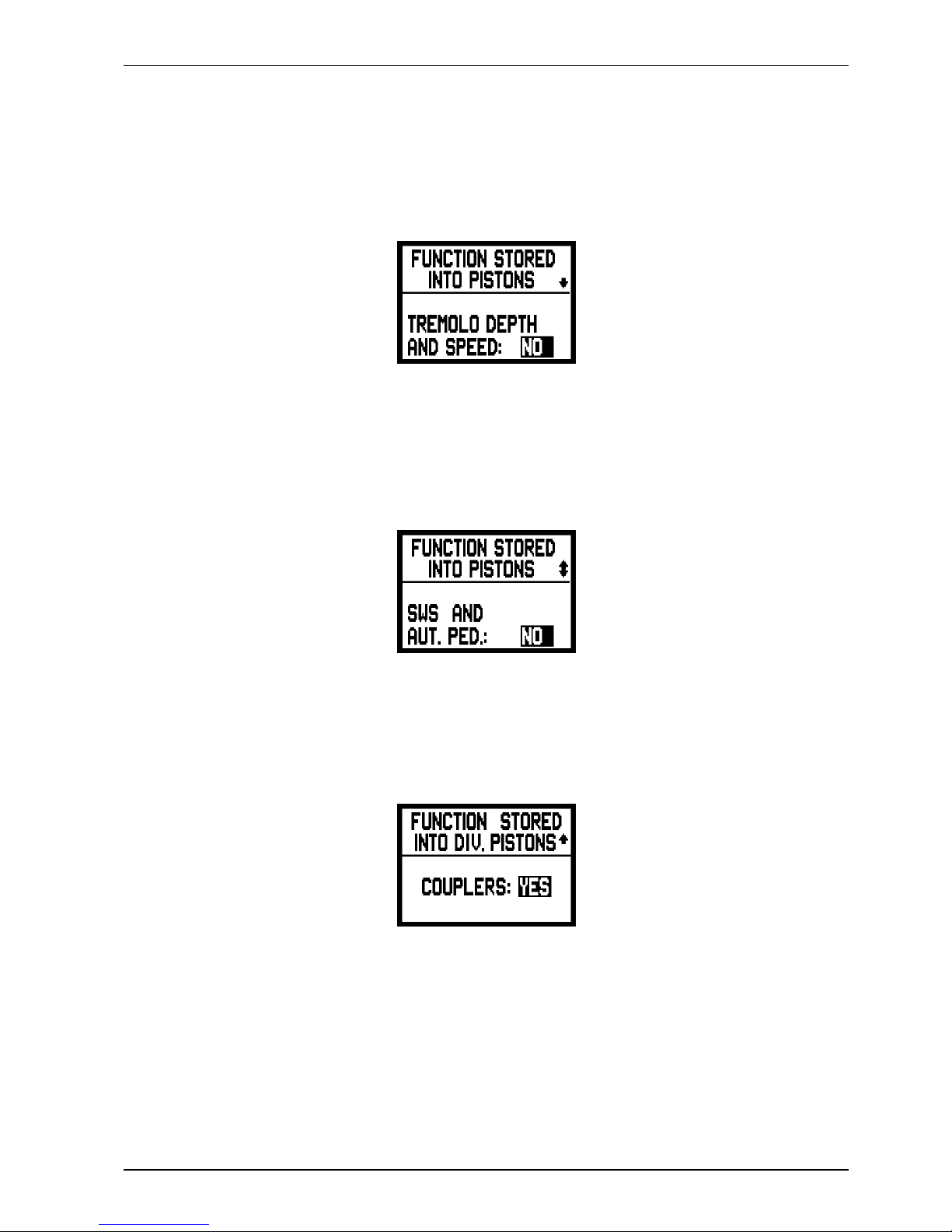
This screen allows you to enable and disable saving of the Tremolo Depth and Speed values, so that you can
obtain Tremolo of different modulation depth and speed by recalling the various combinations. Use the [VALUE
+] and [VALUE -] buttons to select YES to enable saving or NO to disable it.
Now press the [FIELD T] button to display the second saving setting screen:
in which you can decide whether or not to save the status of the All Swells to Swell pedal and the Automatic
Pedal. Here again, set YES to enable saving or NO to disable it.
Press [FIELD T] again to display the last setting,
used to enable or disable saving of the couplers in the divisional combinations.
Finally, press [EXIT] to save the changes made and return to display of the SET UP menu.
7.8 COMBINATION SAVING SETTINGS
The FUNCTION STORED INTO PISTONS function in the SET UP menu allows you to choose what
you wish to save in the general and specific combinations and the Tutti in order to further customise the
organ’s performance features.
After the FUNCTION STORED field is selected in the SETUP menu, the display will show:
Page 32

30
Viscount Chorale 8
Owner’s Manual
8. MIDI
WHAT MIDI IS
The MIDI interface (Musical Instrument Digital Interface) allows instruments of different makes and
kinds to communicate with each other, using this very specific protocol of codes. This allows the creation
of systems of MIDI instruments, offering much greater versatility and control than is possible with single
instruments. To make this communication possible, all MIDI instruments have two or three 5-pin DIN
connectors called:
- MIDI IN: The connector through which the instrument receives the MIDI data transmitted by other
units.
- MIDI OUT: The connector through which the instrument sends the MIDI data it has generated to
other units.
- MIDI THRU: This connector, not always provided on all instruments, is used for connecting several
units in series, since it transmits the MIDI data exactly as they are received by the respective MIDI IN
port.
Most instruments equipped with MIDI interface transmit MIDI messages which specify, for example,
which note has been played and with what dynamic, by means of the MIDI OUT connector. If this
connector is connected to the MIDI IN connector of another MIDI instrument, such as an expander, the
second instrument will respond exactly to the notes played on the transmitter instrument.
The same type of information transfer is used for recording MIDI sequences. A computer or a sequencer
can be used to record the MIDI data generated by the transmitter instrument. If these recorded data are
sent back to the instrument, it automatically repeats the recorded performance.
MIDI is able to transmit a multitude of digital data by means of just one cable, and thus just one connector.
this is thanks to the MIDI channels. There are 16 MIDI channels, and in a similar way as for radio
communications in which two stations can only communicate if they are tuned to the same frequency (or
channel), two MIDI instruments connected together are only able to communicate if the transmitter
instrument channel is the same as the receiver instrument channel.
MIDI messages subdivide into channel messages and system messages. The following is a short description
of these messages:
CHANNEL MESSAGES
NOTE ON
This message is transmitted when a note is depressed on the keyboard. Each Note On message contains the following information:
Note On: when a key has been struck;
Note Number: the key which has been pressed, and therefore the relative note played;
Velocity: note dynamic (i.e. the force applied when the key was struck).
Note messages are expressed as a number from 0 to 127, with middle C represented by number 60.
NOTE OFF
This message is transmitted when a key struck previously is released.
When it is received, the sound of the note relating to the key is switched off. Each Note On message contains the following
information:
Note Off: a key has been released;
Note Number: which key has been released;
Velocity: dynamic (i.e. how fast the note was released).
N.B.:
A Note On message with Velocity=0 is considered equivalent to a Note Off message. The Chorale 8 sends the Note On message
with Velocity=0.
Page 33

31
Viscount Chorale 8
Owner’s Manual
PROGRAM CHANGE
This message is used to select the programs or sounds of the receiver instrument.
There is also a specific standard called General MIDI which describes which sound should be recalled for each Program
Change received. This association is usually described by means of a table included in the user manual of the instrument
which adopts the standard.
This message contains the following information:
Program Change: voice or program change;
Program Change Number: the number of the program or voice to be activated;
CONTROL CHANGE
These are control messages (often associated to trimmers or pedals) used to add expression to the performance, allowing you
to set (and control in real time if necessary) voice parameters such as volume (CC n.7) or the position of the swell pedals (CC
n.11), etc.
This message contains the following information:
Control Change: a controller has been adjusted
Controller Number: which controller has been adjusted
Controller Position: the position of the controller
SYSTEM MESSAGES
SYSTEM EXCLUSIVE
These messages can only be interpreted by an instrument made by the same producer as the transmitter device (in some cases
only by the same model). They mainly relate to the instrument’s sound generation and programming parameters. The Chorale
8 uses these messages to control all the internal parameters and for switching the voices on and off.
REAL TIME
These messages are used for the real-time control of specific modules or functions of a connected instrument. These messages
include the Start, Stop, Pause/Continue and Clock commands.
START: the sequencer has started to record or play back a MIDI sequence
STOP: the sequencer has been stopped
PAUSE / CONTINUE: the sequencer has been set in stop status
CLOCK: the sequencer speed
N.B.
The Chorale 8 does not transmit / receive the messages described above. They are described for your information only.
The Real Time messages also include the Active Sensing code, sent to keep the dialogue between two MIDI instruments alive.
When the receiver instrument does not receive any MIDI data or the Active Sensing code in a time interval of about 300
milliseconds, it considers the MIDI connection to have been deactivated, so it switches off any notes still active. Remember
that the transmission and reception of this message is optional, so not all instruments are equipped to handle it.
To access all the Chorale 8 MIDI settings, select the MIDI option in the MENU screen and press [ENTER].
The functions available are as follows:
o TX/RX CHANNEL: MIDI transmission and reception channel selection.
o SEND PROG. CHANGE: Program Change message transmission.
Page 34

32
Viscount Chorale 8
Owner’s Manual
The four fields displayed correspond to the organ’s four sections. The number alongside identifies the transmission
and reception channel for the section concerned.
As usual, use the [FIELD S] and [FIELD T] buttons to locate the cursor on the display fields and
[VALUE +] and [VALUE -] to select the channel required.
Now press [EXIT] to return to the MIDI menu and save the settings made.
8.2 PROGRAM CHANGE MESSAGE TRANSMISSION
The MIDI Program Change (PG) message allows a specific sound or program (patch) to be recalled in a
connected unit. Therefore, you can use this function to select the voice required from a remote module
(such as an expander) connected to the [MIDI OUT] port directly from the organ itself.
To display the relative video page, select the SEND PROG. CHANGE field in the MIDI menu and press
[ENTER]:
To transmit a PG message, locate the cursor on the section to which the MIDI channel of choice is associated
and use the [VALUE +] and [VALUE -] buttons to set the number of the PG required.
o TX/RX FILTER: MIDI filter setting.
Use the [FIELD S] and [FIELD T] and [ENTER] buttons to select the function required.
Otherwise, press [EXIT] to exit the MIDI submenu and return to display of the MENU screen.
8.1 SELECTING THE CHANNELS
To set the MIDI transmission and reception channels, select the TX/RX CHANNEL field in the MIDI
submenu:
N.B.
- It is not possible to set different reception and transmission channels for the same section.
- MIDI 16 channel cannot be selected since it is the system channel used for the exchange of
internal codes between Viscount instruments.
Page 35

33
Viscount Chorale 8
Owner’s Manual
When each value is selected, the relative PG will be transmitted automatically.
If, for example, the pedal board MIDI A channel is number 3, when 20 is selected beside the “PEDAL”
field, Program Change n. 20 will be transmitted on the MIDI 3 channel.
It is important to underline that the Program Changes set in this screen are saved in the specific and
general combinations. To do this, simply select the PG messages in the screen described above and save
the combination required.
All this is particularly useful when you are using a remote expander, for example, and wish to obtain a
specific voice in combination with the stops activated by means of the combination.
If transmission of the PG is not necessary, saving of the PG can be aborted by selecting the value OFF.
8.3 SETTING THE FILTERS
A MIDI filter is a special function which allows a specific message to be cut out on all the MIDI
channels (if it is a channelled message) in transmission and/or reception.
For example, the Control Change transmission filter allows you not to transmit these MIDI messages on
the [MIDI OUT] port on all the MIDI channels controlled by the organ.
Similarly, the reception filter cuts out the CCs received by the organ by means of the [MIDI IN] port on
all the channels (i.e. the CCs are not applied).
To set up the MIDI filters select the TX/RX FILTERS field in the MIDI submenu. The following screen
appears:
The filters for the following messages (shown in the top left-hand corner of the display) can be switched on and
off:
o CC: Control Change (control messages)
o PG: Program Change (messages for selecting programs/voices)
o SYSEX System Exclusive (system exclusive messages)
o REAL: Real Time messages (Active Sensing).
The right-hand side of the display contains the fields for the setting the filters for each type of message.
The settings are:
- NO/NO: both filters off.
- YES/NO: filter only active on messages transmitted
- NO/YES: filter only active on messages received
- YES/YES: filter active on both received and transmitted messages.
When a filter is activated the relative MIDI message is not transmitted / received.
Press [EXIT] to return to the MIDI menu and save the new settings.
Page 36

34
Viscount Chorale 8
Owner’s Manual
9. UTILITY FUNCTIONS
The UTILITY submenu in the MENU contains the organ’s general utility functions.
To display this menu, select the UTILITY option in the MENU screen and press [ENTER].
This submenu consists of two video pages, displayed using the [FIELD S] and [FIELD T] buttons:
The fields displayed are:
o TUNING: fine tuning of the instrument within a range of 415.3 Hz to 466.2 Hz (adjustments in steps
of one tenth of a Hz). The frequency value refers to the third A.
o CONTRAST: display contrast.
o FACTORY SETTING: restores the factory settings.
o LOCK ORGAN: organ lock function.
9.1 STYLE COPY
The STYLE COPY function in the UTILITY submenu allows the contents of a style (i.e. the registers and
their volumes, the reverb type and the equaliser settings) to be copied into another User style.
This is particularly useful to avoid having to make settings which already exist, when the user wishes to
programme a style starting from a preset style (Baroque, French, English or American) or a style
programmed earlier (in another User style, for example).
To recall this function, select the STYLE COPY option in the UTILITY video page; the display will
show:
In this video page, select the style you wish to copy by setting it in the SRC field, and the destination style in the
DST field. As the display prompts, press [ENTER] to confirm the copy or EXIT to abort the function.
Page 37

35
Viscount Chorale 8
Owner’s Manual
the system prompts you to confirm, warning that all the settings you have made will be irretrievably lost.
To confirm the Factory Setting procedure press the [ENTER] key, or to abort the operation simply press [EXIT].
Once the Factory Setting operation has been started, the display will show a standby screen for the time taken to
reload the factory data:
9.2 FACTORY SETTING
The Factory Setting procedure allows you to restore the factory settings of all the instrument’s internal
functions, deleting all the changes made by the user.
To recall this function, use usual buttons to select the FACTORY SETTING option in the UTILITY
submenu; the display will show:
Before making the copy, the system warns the user that the style shown on the display is about to be overwritten
and its data will be irretrievably lost. Here again, press [ENTER] to continue or [EXIT] to abort the copy and
return to the UTILITY submenu.
after which the instrument will be rebooted automatically.
Page 38

36
Viscount Chorale 8
Owner’s Manual
9.3 ACCESSING THE MODIFICATION FUNCTIONS
When the user considers it necessary to prevent modification of the organ’s setup, the LOCK ORGAN
function can be used. This prevents modification of the combinations, Tutti and Crescendo steps, and the
only video pages displayed will be the main and section volume pages. The light in the [S] piston goes
out to indicate that the organ lock function is active.
To do this, select the LOCK ORGAN option in the UTILITY and press [ENTER]:
To release the lock and restore access to the functions described at the start of this section, press the [ENTER]
button or the [MENU] piston. The display will prompt input of the password:
As usual, use the [FIELD S] and [FIELD T] buttons to move the cursor and [VALUE +] and [VALUE -] to
adjust the values, then [ENTER] to confirm. If the password is correct, the display will return to the UTILITY
submenu; otherwise, the following video page will appear:
stating that the password was incorrect and it must be entered again.
Page 39

37
Viscount Chorale 8
Owner’s Manual
10. APPENDIX
10.1 DEMONSTRATION SONGS
The organ has a number of demonstration (demo) tracks to allow you to fully appreciate the quality its
sound qualities and/or those of the changes you have made.
To recall playback of the demo tracks, select the DEMO SONG option from the MENU screen.
Use the [FIELD S] and [FIELD T] buttons to select each piece of music. Press [ENTER] to start and
stop each piece. Press [EXIT] to leave the DEMO SONG function.
10.2 VOICE LOCAL OFF
Setting a voice in Local Off mode means that it will not be played by the organ’s internal sound generation
system, but the relative MIDI (System Exclusive) message will be transmitted, so that it can be turned on
and played on a connected instrument.
To set a voice Local Off press the [S] (Set) button, keep it pressed and also press the [C] (Cancel) button.
All the draw-stops will come on and the display will show the video page:
To set a voice in Local Off mode, press its draw-stop so that its light goes out.
After setting the setup required, press [S] and [C] together to save it.
Accessing the Local Off setting function after this will trigger display of the status of the voices as
follows:
- Light on: voice in Local On mode (plays with internal generation)
- Light off: voice in Local Off status
During normal operation, when a voice in Local off mode is switched on, the draw-stop flashes three
times then remains constantly lit.
Page 40
38
Viscount Chorale 8
Owner’s Manual
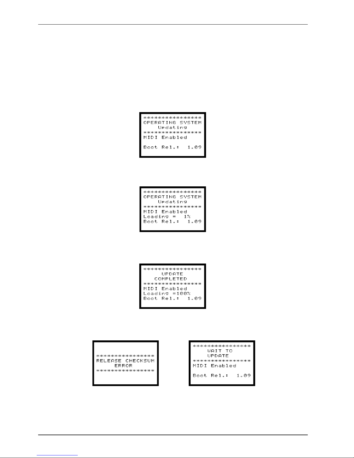
10.3 UPGRADING THE OPERATING SYSTEM
Upgrading the organ’s operating system requires use of a MIDI file (extension .MID) reader, by means of
which the data in the upgrade file can be transmitted to the organ. A hardware device used for MIDI
sequencing, or a computer software package capable of processing this type of file, may be used. Connect
the MIDI data output port of the transmitter device (which may be the MIDI OUT connector of a hardware
module or of a serial or USB / MIDI interface or Joyport if a computer is used) to the [MIDI IN] connector
of the Chorale 8.
Start the updating procedure; when the organ starts to receive the data, the display will show :
now the display will start to show a percentage of the data received.
At the end of the procedure, the following video page is displayed:
When the organ is switched on, if the display shows one of the following video page:
If the display looks like the one shown on the left, you must turn the organ off and switch it back on whilst holding
down the [FIELD S], [FIELD T] and [EXIT] buttons at the same time. You can then repeat the updating
procedure. If the display looks like the one shown on the right it is possible to re-transmit the MIDI files straight
away without having to manually recall the updating procedure.
Page 41

Viscount Chorale 8 Version: 1.0
Classic Organ Date: 28/09/2012
REMARKS
BASIC Default
CHANNEL Changed
MODE Default
Messages
Altered
NOTE
NUMBER True Voice
VELOCITY Note ON
Note OFF
AFTER Key's
TOUCH Ch's
PITCH BENDER
CONTROL 7 Volume
CHANGE 11 Expression
64 Sustain
120 All sound off
121 Reset All Controllers
123 All Notes Off
PROGRAM
CHANGE True#
SYSTEM EXCLUSIVE
SYSTEM Song Pos
COMMON Song Sel
Tune
SYSTEM Clock
REAL TIME Commands
AUX Local On-Off
MESSAGES All notes off
Active Sense
Reset
NOTES:
Mode 1: Omni On, Poly Mode 2: Omni On, Mono O=YES
Mode 3: Omni Off, Poly Mode 4: Omni Off, Mono X=NO
X
X
X
X
X
X
O
X
X
O
O
X
X
O
X
X
OO
X
X
O
O
O
O
OX
O
O
O
O
O
O
OO
X
X
X
X
XX
30÷101
36÷96
0÷127
30÷101
O
X
O
X
Mode 3
********
********
Mode 3
********
********
MIDI IMPLEMENTATION CHART
FUNCTION… TRANSMITTED RECEIVED
1÷15
1÷15
1÷15
1÷15
Page 42

Page 43

Disposal of old Electrical & Electronic Equipment (Applìcable throughout the European Union
and other European countries with separate collection programs)
Dir. 2002/95/CE, 2002/96/CE e 2003/108/CE
This syrnbol, found on your product or on its packaging, indicates that this product should not be
treated as household waste when you wish to dispose of it. Instead, it should be handed overt to an
applicable collection point for the recycling of electrical and electronic equipment. By ensuring this
product is disposed of correctly, you will help prevent potential negative consequences to the
environment
and human health, which could otherwise be caused by inappropriate disposal of this product. The
recycling of materials will help to conserve natural resources. For more detailed information about the
recycling of this product, please contact your local city offi ce, waste disposal service or the retail store
where you purchased this product.
This product complies with the requirements of EMCD 2004/108/EC and LVD 2006/95/EC.
FCC RULES
NOTE: This equipment has been tested and found to comply with the limits for a Class B digital Device, persuant to Part 15 if the FCC
Rules. These limits are designed to provide reasonable protection against harmful interference in a residential installation. This
equipment generates, uses and can radiate radio frequency energy and, if not installed and used in accordance with the instruction,
may cause harmful interference to radio comunications. However, there is no guarantee that the interference will not occur in a
particular installation. If this equipment does cause harmful interference to radio or television reception, which can be determinated by
turning the equipment off and on, the user is encuraged to try to correct the interference by one or more of the following measures:
- Reorient or relocate the receiving antenna.
- Increase the separation between the equipment and receiver.
- Connect the equipment into an outlet on a circuit different from that to which the receiver is connected.
- Consult the dealer or an experienced Radio/Tv technician for help.
The user is cautioned that any changes or modification not expressly approved by the party responsable for compliance could void the
user’s authority opearate the equipment.
INFORMATIONS FCC
NOTE : Cet instrument a été controlé et il est garanti pour etre en conformité avec les spécifications techniques établies pour les
dispositifs numériques de la « Classe B » selon les normes de protection contre les interférences avec d’autres dispositifs électroniques
environnants. Cet appareil produit et utilise des fréquences radio. S’il n’est pas installé et utilisé selon les instructions contenues dans le
mode d’emploi, il peut générer des interférences. L’observation des normes FCC ne garanti pas qu’il y aura aucune interférence. Si cet
appareil est la cause d’ interférences avec une réception Radio ou TV, il est possible
de le vérifier en éteignant puis en allumant l’instrument : Vous pouvez alors résoudre le problème en suivant les procédures suivantes :
- déplacer ou orienter l’antenne de l’appareil avec lequel se manifeste l’interférence.
- déplacer cet instrument ou l’appareil avec lequel se produit l’interférence
- connecter cet instrument à une prise de courant différente afin de mettre les deux appareils sur deux circuits différents.
- consulter le revendeur ou un technicien radio/tv pour d’autres renseignements.
D’éventuelles modifications non approuvées par le constructeur peuvent annuler votre garantie de l’appareil.
Page 44

viscount
Viscount International S.p.A.
Via Belvedere Fogliense 154 – 47836 Mondaino (RN), ITALY
Tel: +39-0541-981700 Fax: +39-0541-981052
Website: www.viscount.it
Distribuito in Italia da
TITAN MUSIC S.A.
Strada Genghe di Atto, 80
47892 Acquaviva - Repubblica di San Marino
Tel. 0549-999164
fax 0549-999490
 Loading...