

Page 1
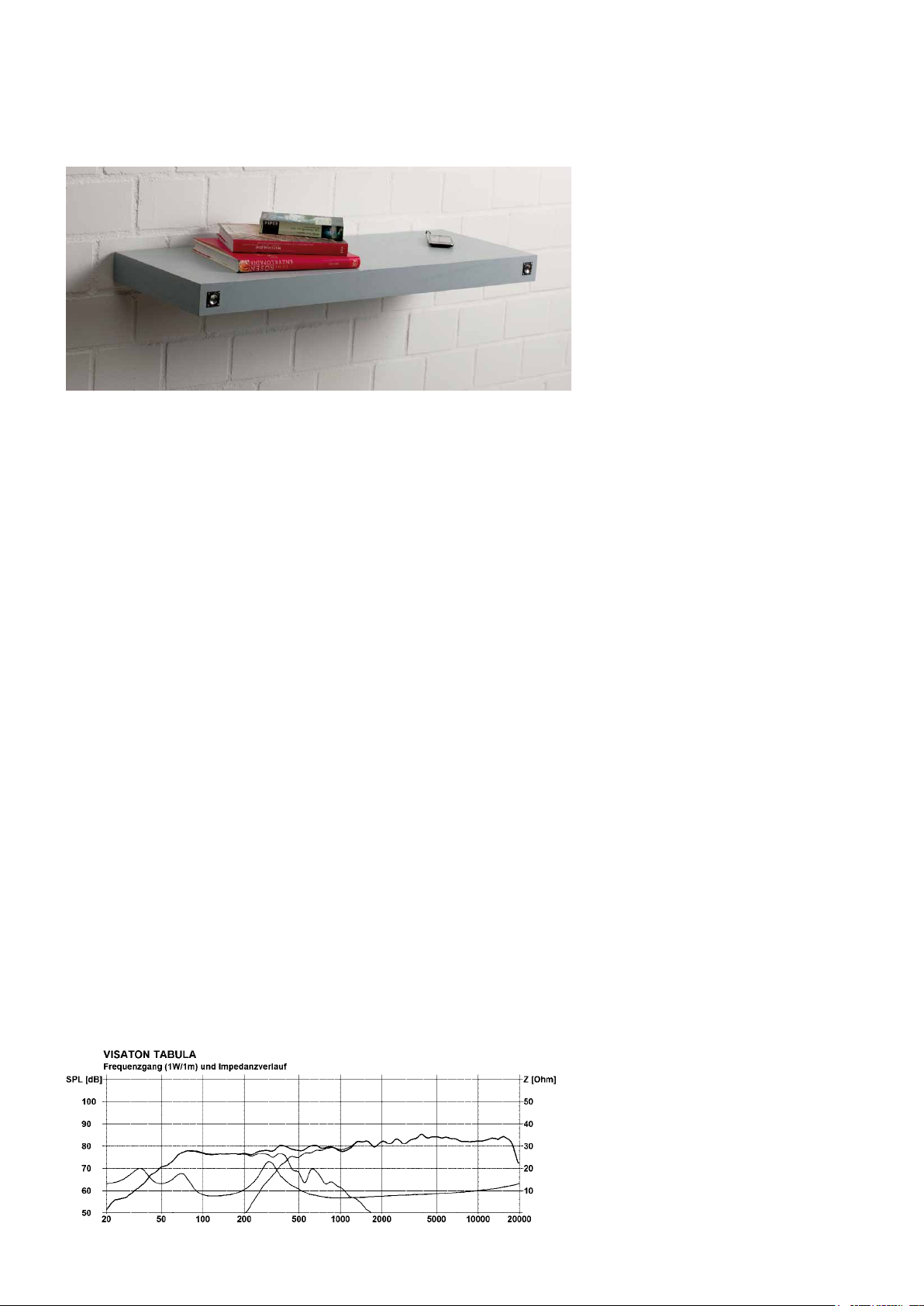
Tabula
Foto: Selbst ist der Mann, www.selbst.de
Eigenschaften und Klang
Die T
abula
ist ein als Regalbrett getarnter
Stereolautsprecher mit äußerst vielseitigen Anwendungsmöglichkeiten. Sie
kann individuell als Bücherregal, TVUntergestell, Arbeitsunterlage oder reine Audioanlage genutzt und als Lautsprecher unsichtbar im Raum integriert
werden.
Den Hauptteil der Wiedergabe übernehmen die Miniaturbreitbandlautsprecher
BF 32, welche trotz geringer Abmessung
erstaunlich erwachsen klingen und mit
technischen Details wie Aluminiummembran und Neodymmagnet glänzen.
Das Bassfundament der Tabula übernimmt ein seit vielen Jahrzehnten erhältlicher und aufgrund seines hervorragenden Preis-Leistungs-Verhältnisses
geschätzter Lautsprecher, der W 100 S.
Dieser sorgt im passend abgestimmten
Bassreflexgehäuse für sehr guten Tiefgang, welcher trotz seiner geringen Größe vergleichsweise pegelfest ist.
Die Kombination der drei Komponenten, gepaart mit einer pfiffigen Weichenschaltung und den durchdachten Details, ergeben ein klangstarkes Stereosystem, welches versteckt im Raum integriert werden kann. Mit einem Miniaturverstärker (z.B. VISATON AMP 2.2)
und einem MP3-Player kann die Tabula
zu einem vollwertigen HiFi-System aufgerüstet werden.
Characteristics and sound properties
Tabula is a stereo loudspeaker cabinet
designed to look like a shelf that is extremely versatile. It can be used as a
bookshelf, TV stand, worktop or hifi rack
and integrated invisibly into the room as
a loudspeaker.
The main drivers are the miniature fullrange 8 ohm BF 32 speakers which, despite their modest size, sound remarkably
grown-up and incorporate such technical details as aluminium diaphragms and
neodymium magnets.
The bass department of the Tabula sys-
tem is provided by the 8 ohm W 100 S,
an excellent value-for-money bass driver that has been popular for decades for
that very reason. In the correspondingly
designed bass reflex cabinet, this driver
generates excellent low-frequency bass
that is remarkably firm despite the size
of the speaker.
The combination of these three components, coupled with a sophisticated
crossover and the design of the system
details produces a powerful stereo sound
system which can be invisibly integrated into the room. Supplemented with a
miniature preamp (such as the VISATON
AMP 2.2) and a simple MP3 player, the
T
abula
becomes a full-scale Hifi system.
46 HiFi Bauvorschläge / Building Suggestions for Loudspeakers 2011/2012
Page 2
Nennbelastbarkeit Rated power 20 W
Musikbelastbarkeit Maximum power 30 W
Nennimpedanz Nominal impedance 8Ω
Übertragungsbereich Frequency response (–10 dB) 50–20
Mittl. Schalldruckpegel Mean sound pressure level 80 dB (1 W/1 m)
Trennfrequenz Cut-off frequency 410 Hz
Gehäuseprinzip Principle of Housing Bassreflex / bass reflex
Gehäusemaße Cabinet
Nettovolumen Net volume 2 x 0,23 l + 10,5 l
Höhe Height 67 mm
Breite Width 1000 mm
Tiefe Depth 350 mm
000 Hz
Tabula
Bestückungsliste für 1 Box
Der Bausatz enthält alle in dieser Bestückungsliste aufgeführten Bauteile,
jedoch kein Gehäuse.
Breitbänder BF32–8Ω 2St.
Tiefmitteltöner W100S–8Ω 1St.
Frequenzweiche Tabula 1 St.
Terminal LK 2 NG 2 St.
Dämpfungs- Polyestermaterial wolle 0,5 Btl.
Senkkopfschrauben 3,5 x 25 mm 9 St.
Kabel 2 x 1,5 mm2 3 m
Weiterhin notwendig sind folgende Bauteile (nicht im Lieferumfang enthalten):
M10-Gewindestange
(L=100 cm) als Halterung 1 St.
M10-Mutter 2 St.
Dübel für M10-Gewindestange 2 St.
Holzschrauben für BF 32
(2 mm Durchmesser) 8 St.
Scharnier für Abdeckung des
Verstärkergehäuses 1 St.
Verriegelung für Abdeckung des
Verstärkergehäuses (z.B. Schieberiegel) 1 St.
Miniaturverstärker* 1 St.
*Sofern als Miniaturverstärker der
VISATON AMP 2.2 bzw. AMP 2.2 LN genutzt werden soll, sind weitere Bauteile
notwendig:
Adapterkabel Stereo
Klinke – Stereo Klinke 1 St.
Adapterkabel Stereo
Klinke – 4 offene Kabelenden 1 St.
Netzteil für AMP 2.2 1 St.
Folgendes ist zu beachten: Der Miniaturverstärker AMP 2.2 ist in der Leistungsabgabe begrenzt. Normale Zimmerlautstärke kann unverzerrt wiedergegeben
werden. Bei höheren Schalldruckpegeln
empfiehlt sich eine größere Verstärkereinheit, die aufgrund der speziellen Frequenzweiche nicht als Brückenverstärker
ausgeführt sein darf.
Zuschnittliste für 1 Box
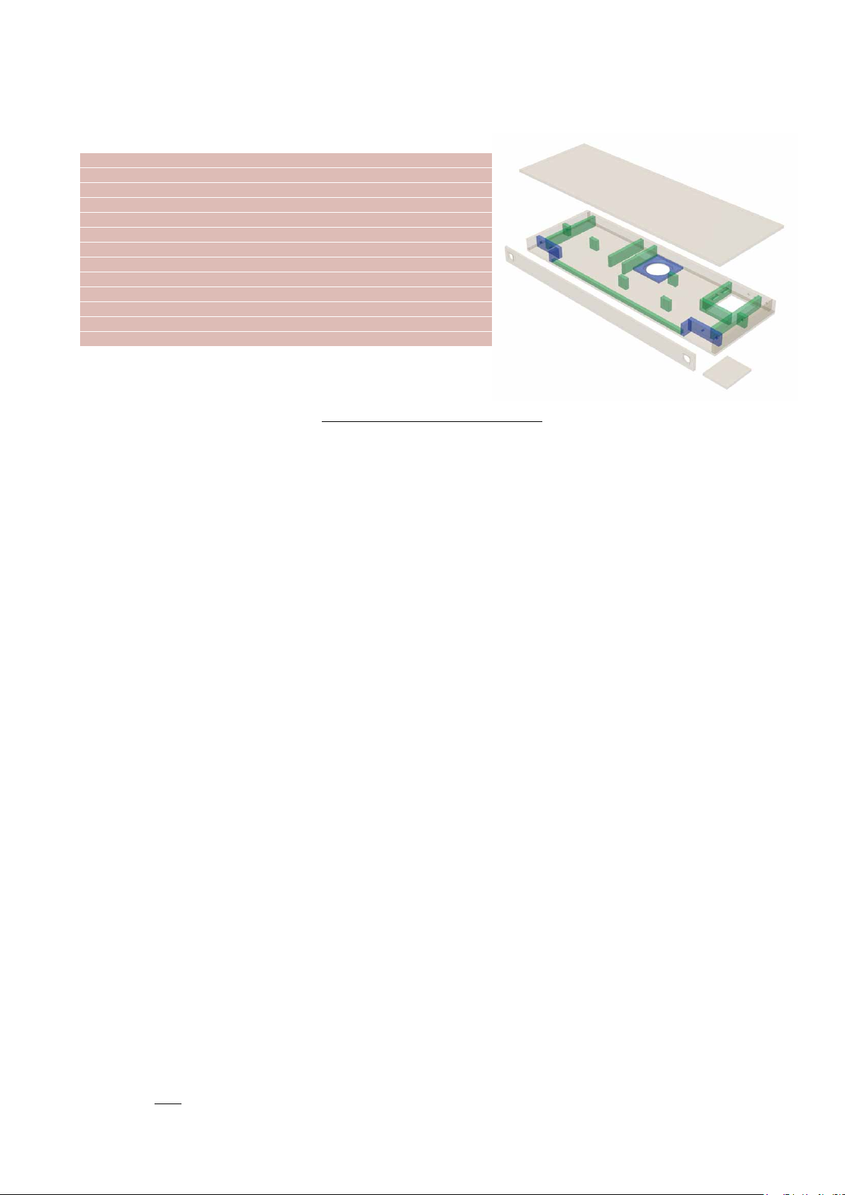
Teile Maße (mm) Anzahl
Material:
Front 67 x 1000 1
Deckel und Boden 340 x 1000 2
Abdeckung für
Verstärkergehäuse 110 x 120 1
Brett für Tieftöner 140 x 140 1
Material:
Rückwand 47 x 968 1
Seitenwände 47 x 340 2
Bassreflex
Seitenwände 47 x 190 2
Brett für Halterung (a) 47 x 268 2
Brett für Halterung (b) 47 x 36 2
Brett für Breitbändergehäuse (a) 47 x 140 2
Brett für Breitbändergehäuse (b) 47 x 40 2
Versteifungen 47 x 40 4
Brett für Verstärkergehäuse (a) 47 x 150 1
Brett für Verstärkergehäuse (b) 47 x 136 1
Material: 15 mm Rechteckleiste
Hilfsleiste 15 x 688 1
10 mm Spanplatte oder MDF
16 mm Spanplatte oder MDF
HiFi Bauvorschläge / Building Suggestions for Loudspeakers 2011/2012 47
Page 3
Tabula
Component parts list for 1 box
The kit includes all the components listed here but not the cabinet.
Fullrange
speaker BF328Ω 2pcs.
Woofer W100S8Ω 1pc.
Crossover
Terminal LK 2 NG 2 pcs.
Damping Polyester
material wool 0.5 bag
Countersunk
screws 3.5 x 25 mm 9 pcs.
Cable 2 x 1.5 mm
Tabula 1 pc.
2
3 m
intend to run it at higher sound pressure levels, we recommend using a larger
amp, which may not be designed as a
bridge amplifier, because of the special
crossover.
Cabinet parts list for 1 box
Parts Size (mm) Quantity
Material: 10 mm chipboard or MDF
Front panel 67 x 1000 1
Top and bottom panel 340 x 1000 2
Cover panel for
amplifier cabinet 110 x 120 1
Panel for woofer 140 x 140 1
Material: 16 mm chipboard oder MDF
Rear panel 47 x 968 1
Side panels 47 x 340 2
Bass reflex side panels 47 x 190 2
Panel for mounting (a) 47 x 268 2
Panel for mounting (b) 47 x 36 2
Panel for fullrange
speaker (a) 47 x 140 2
Panel for fullrange
speaker (b) 47 x 40 2
Braces 47 x 40 4
Panel for amplifier
cabinet (a) 47 x 150 1
Panel for amplifier
cabinet (b) 47 x 136 1
Material: 15 mm rectangular profile
Rectangular profile 15 x 688 1
The following parts are also necessary
(not included in speaker kit):
M10 - thread bar
(L = 100 cm) for wall mounting 1 pc.
M10 - screw nut 2 pcs.
Wall plug for M10 - thread bar 2 pcs.
Wood screw for BF 32
(2 mm diameter) 8 pcs.
Hinge for cover panel
of the amplifier housing 1 pc.
Locking mechanism for
cover panel (e.g. slide bar lock) 1 pc.
Miniature amplifier* 1 pc.
*If a VISATON AMP 2.2 or AMP 2.2 LN
amplifier is to be used, some more components will be necessary:
Cable: Stereo phone jack –
Stereo phone jack 1 pc.
Cable: Stereo phone jack –
4 open cable ends 1 pc.
Power supply for AMP 2.2 1 pc.
Please note the following: the AMP 2.2
amplifier has a limited output. It is quite
capable of producing normal undistorted
volume for a standard room but, if you
48 HiFi Bauvorschläge / Building Suggestions for Loudspeakers 2011/2012
Page 4

Tabula
Aufbau
Der Aufbau der T
abula
ist äußerst aufwendig und aufgrund der flachen Bauweise etwas kniffelig. Für Anfänger im Lautsprecherselbstbau mit wenig Erfahrung im Schreinerhandwerk ist die T
abula
daher nicht zu
empfehlen.
Für den Aufbau ist eine präzise arbeitende
Handkreissäge mit Führungsschiene oder
eine Tischkreissäge unumgänglich, da Baumärkte üblicherweise nur Holzzuschnitte bis
100 mm durchführen. Des Weiteren wird eine Oberfräse mit Zirkelaufsatz und verschiedenen Fräsern (Zylinderfräser, Bündigfräser,
Fräser für Fasen und Rundungen) sowie diverse Bohrer benötigt.
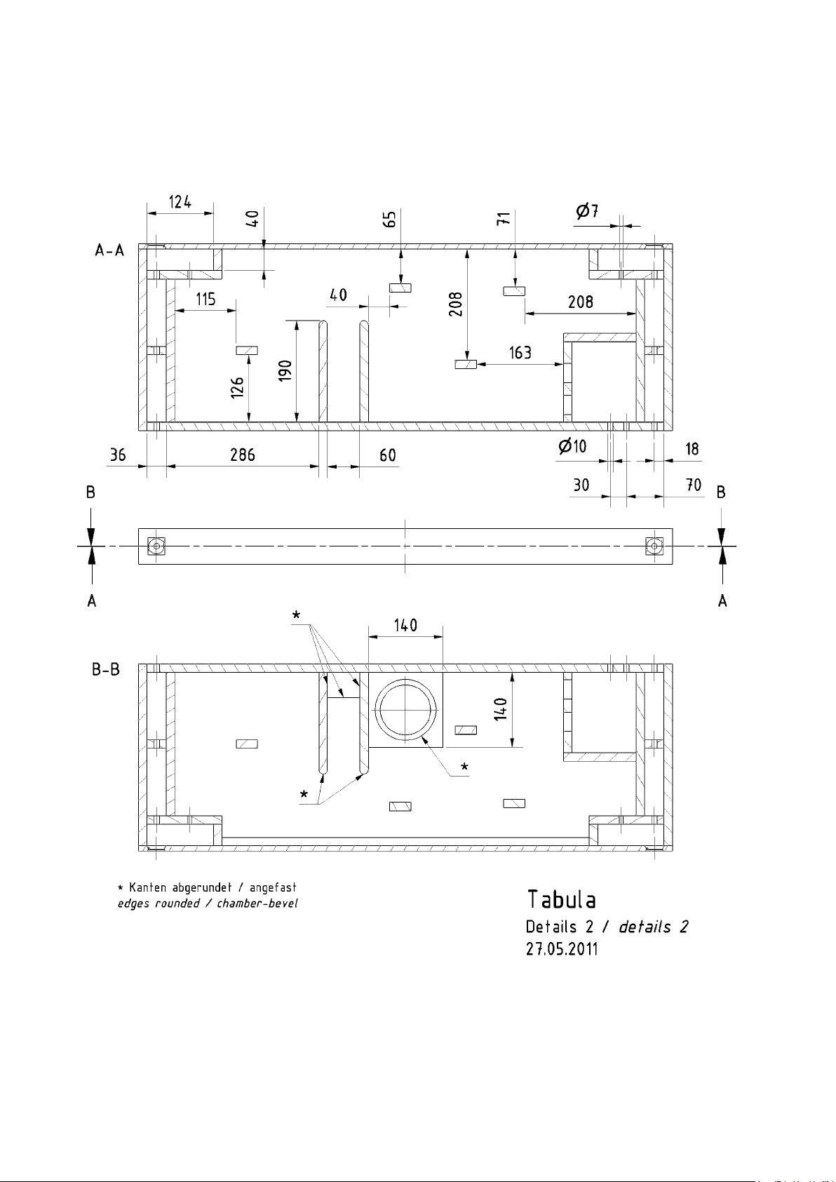
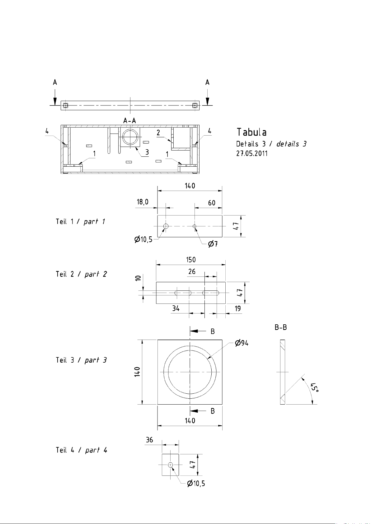
Zuerst werden die einzelnen Bretter laut den
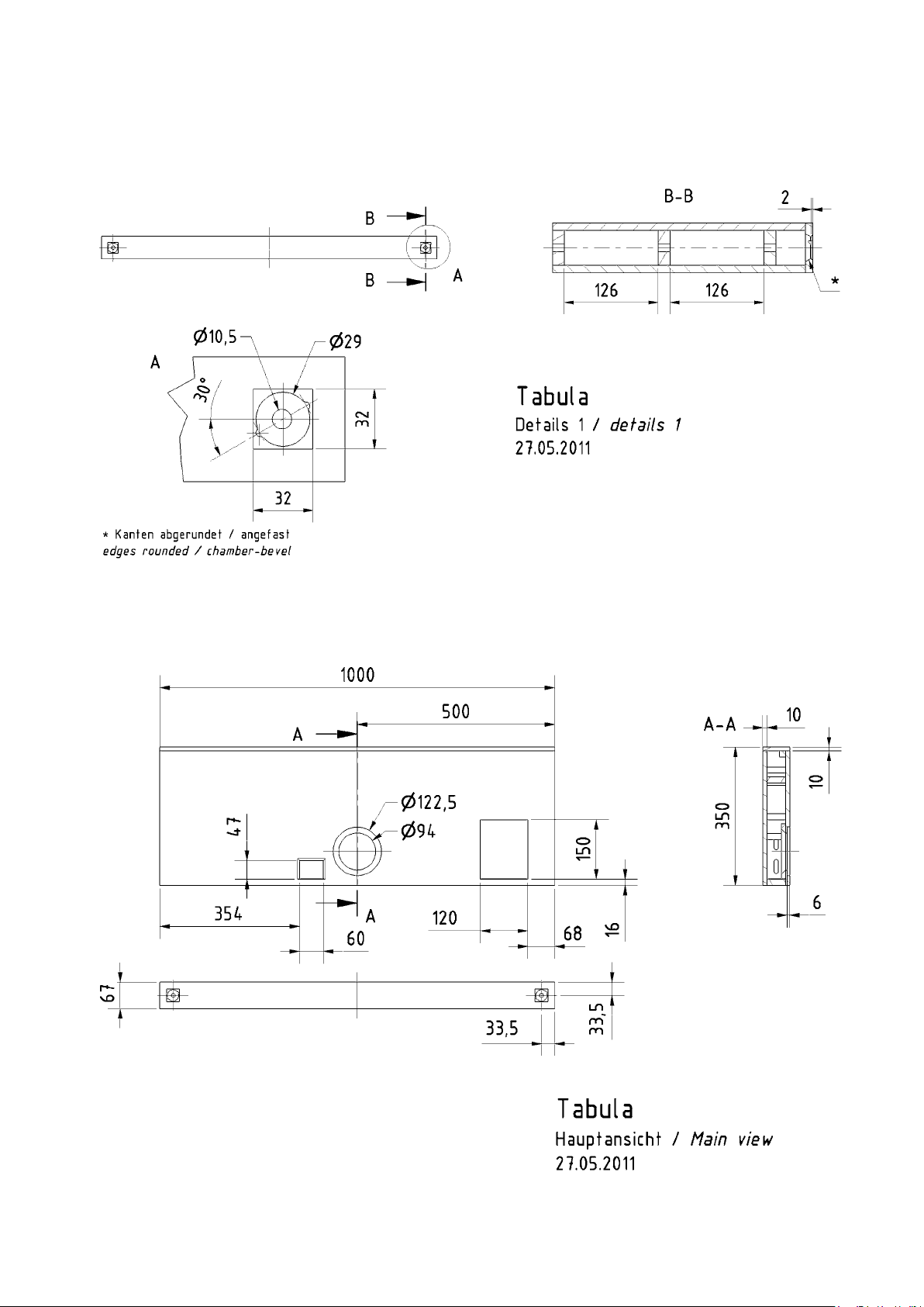
technischen Zeichnungen ausgesägt. Es
empfiehlt sich, die entsprechenden Löcher
und Öffnungen vor dem Verleimen anzubringen. Hierbei ist vor allem die Aufnahme
des Breitbandlautsprechers BF 32 auf der
Frontwand kritisch und filigran. Sofern kein
passendes Werkzeug zur Verfügung steht,
kann man bei der 10-mm-MDF-Frontplatte
folgendermaßen verfahren:
– 29-mm-Loch mittels Forstnerbohrer
bohren (ggf. kleineres Loch bohren und
auffeilen)
– Anbringen der Versenkung des Laut-
sprechers, z.B. mittels Teppichmesser
(kleine Klinge) und Stechbeitel
– Anbringen der rückseitigen Fase mit-
tels Raspel und Feile (dies ist notwendig, da die rückseitigen Öffnungen des
Lautsprechers sonst verdeckt wären)
– Freilegen der Ohren des Anschluss-
terminals mittels Feile
Sollten individuelle Veränderungen erwünscht sein, sollte dies bereits im jetzigen
Zustand berücksichtigt werden. Dies können z.B. ein Fach für einen MP3- Player im
Deckel, eine Kabeldurchführung an entsprechenden Stellen oder Schutzgitter bzw. Abdeckungen für die Lautsprecher sein. Ebenfalls sollten im jetzigen Zustand entsprechende Kabelverlegungen vom Regal zur
Wand bedacht werden. Hierfür sind in der
Zeichnung 10-mm-Löcher auf der Rückseite vorgesehen, die ebenfalls individuell angepasst werden können.
Um später im zusammengebauten Zustand
die einzelnen Lautsprecher, Anschlussklemmen etc. so einfach wie möglich anbringen
zu können, sollten die Schraubpunkte bereits im noch nicht verleimten Zustand vorgebohrt werden.
Nachdem alle Bretter vorbereitet wurden,
kann der Zusammenbau beginnen. Die Ta-
bula
wurde so konstruiert, dass der Boden
für spätere Wartungen etc. abnehmbar ist.
Daher sollte man den Aufbau mit dem Deckel beginnen. Auf eine ebene Fläche gelegt, können so die einzelnen Bretter, bis auf
den Boden, Stück für Stück auf den Deckel
aufgeleimt werden (ggf. hilft ein Vorzeichnen der Positionen). Als nächstes werden
die inneren Kanten der verleimten Bretter
mit Holzleim bestrichen, so dass das Gehäuse später keine ungewollten Undichtigkeiten besitzt. Nachdem alles getrocknet ist,
werden die Positionen der einzelnen Bretter auf die Bodenplatte übertragen, vorgebohrt und auf der Außenseite passend für
eine bündige Verschraubung mittels Senkkopfschrauben gesenkt. Pro Versteifungsbrett (40 x 16 mm) ist eine Schraube ausreichend. Für alle anderen Bretter sollte eine sinnvolle Anzahl von Schrauben gewählt
werden, so dass die Bodenplatte stabil und
fest mit allen Wänden, Versteifungen und
Zwischenbrettern verschraubt werden kann.
Im darauffolgenden Schritt kann mit dem
Verlegen der bereits vorkonfektionierten
und an der Frequenzweiche angelöteten
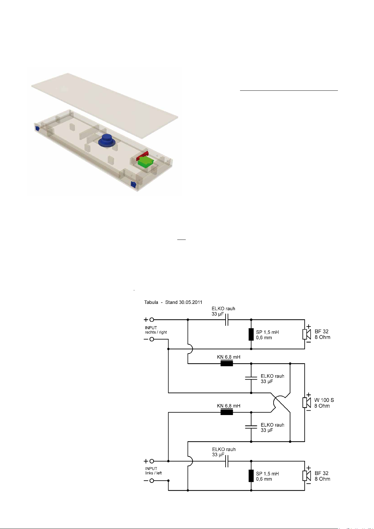
Kabel begonnen werden. Die Frequenzweiche kann zwischen Tiefmitteltönerausschnitt und Anschlussklemmen im Gehäuse
platziert werden. Da die Kabel durch kleine 7-mm-Öffnungen zu den Breitbändern
BF 32 gelegt werden, müssen diese im
Nachhinein z.B. mittels Heißkleber wieder
abgedichtet werden.
Der nächste Schritt ist das Einfügen des
Dämpfungsmaterials. Hierbei ist etwa ein
Zehntel der Matte pro Breitbändergehäuse für später aufzubewahren. Der restliche
Anteil kann lose im Gehäuse verteilt werden. Hierbei hilft ein vorheriges Zerlegen
der Dämpfungsmatte in mehrere kleinere
Stücke. Nach diesem Arbeitsschritt wird
die Bodenplatte verschraubt. Gegebenenfalls kann ein Dichtungsband angebracht
werden, um entsprechende Unebenheiten
auszugleichen.
Nun kann man mit der optischen Gestaltung
des Gehäuses beginnen (lackieren, folieren,
furnieren, bekleben…) und danach den Tiefmitteltöner W 100 S sowie die beiden Anschlussklemmen verlöten und anschrauben.
Im nächsten Arbeitsgang werden die M10Gewindestangen auf eine passende Länge
zurechtgeschnitten. Am einfachsten halbiert
man zunächst die 1 m lange Gewindestange
und sägt sie nach der ersten Anprobe zu-
recht. Die Stangen müssen dabei gut in der
Wand fixiert sein (z.B. mittels Montage-Kit)
und durch die Löcher auf der Rückseite des
Holzgehäuses bis hinter beide Breitbänderöffnungen ragen. Nachdem die T
abula
an
der Wand auf die Gewindestangen geschoben wurde und alle Anschlusskabel verlegt
wurden, kann eine Fixierung mit Muttern
durch das Breitbändergehäuse stattfinden.
Zum Schluss werden die vorher ausgesonderten Dämpfungsmaterialstücke in
die Breitbändergehäuse gestopft und die
BF 32 verlötet und angeschraubt. Sollten
dabei keine passenden Schrauben gefunden werden können, kann man auch die
Verschraubungspunkte des Lautsprechers
vergrößern oder für entsprechende Senkkopfschrauben modifizieren. Diese Modifikationen lassen jedoch die Garantieansprüche verfallen.
Bedämpfung
Die mitgelieferte Dämpfungsmatte wird im
Gehäuse locker verteilt. Dabei sollte etwa
ein Zehntel der Matte pro Breitbändergehäuse genutzt werden. Der restliche Anteil
kann in handliche Stücke geschnitten und
im Gehäuse verteilt werden. Es ist darauf
zu achten, dass die Bassreflexöffnung frei
bleibt und nicht durch Dämpfungsmaterial
verstopft wird.
HiFi Bauvorschläge / Building Suggestions for Loudspeakers 2011/2012 49
Page 5

Tabula
Construction
The construction of the Tabula system
is complex and, as a result of its flat
design, difficult to build.
recommended for beginners in loudspeaker construction with little experience in carpentry.
The construction phase assumes you
have a very accurate hand-held circular
saw with a guide rail or table-mounted
circular saw, because DIY shops tend
only to do parts down to 100 mm. In
addition, you will need a router with a
circular adapter and various router cutters (straight cutter, edge trimmer, cutters for chamfers and rounded edges),
and a range of drill bits.
First, cut out the individual boards in
accordance with the technical drawings. We recommend cutting all the
holes and cut-outs before you glue
boards together. The fitting of the fullrange BF 32 driver in the front panel
is particularly critical and requires very
fine carpentry skills. If no suitable tools
are available, it is possible to proceed
as follows for the 10 mm MDF front
panel:
– Drill a 29 mm hole with a Forstner
drill bit (or a smaller hole which you
can then file to size)
– Make the recess for the speaker,
e.g. with a carpet knife (small blade)
and fine wood chisel
– Make the chamfer on the back us-
ing a rasp and file (this is necessary
because otherwise the rear openings of the loudspeaker will be covered)
– Free up the terminal connections
using a file
If you are planning any individual enhancements, this is the best time to
make them. These might include a recess for an MP3 player in the lid, a cable cut-through in a particular place or
grilles or covers for the loudspeakers.
This is also the time to plan the paths
for the wires to the wall. The drawing
shows 10 mm holes ion the rear for
this purpose but they can be adapted
to suit personal preferences.
To enable you to attach the individual
drivers, terminals etc. easily at a later
point, it makes sense to predrill the
screw holes at this stage before gluing
the parts together.
Tabula is not
Once all the boards have been prepared, it is possible to start building.
Tabula has been designed to allow
The
the base to be removed at a later time
for any maintenance that may be necessary, so it makes sense to begin with
the lid. Lay the parts on a flat surface
and attach them one at a time (except
the base) to the lid (marking the positions in advance may make this easier).
Next, apply wood glue to the inner edges of the boards after they have been
stuck together to ensure that the cabinet does not have any leaks later. Once
all the joints have completely dried,
mark the positions of the individual
boards on the base, predrill them and
countersink the holes so that the countersunk screws are completely flush at
the end. One screw each should be
enough for the strengthening struts
(40 x 16 mm). For all the other boards,
choose a reasonable number of screws
to enable the base to be firmly screwed
to the wall panels, strengthening struts
and intermediate boards.
In the next step, you can start to lay the
wires, which should have been ready
made up and soldered to the crossover
by now. The crossover can be placed
between the cut-out for the mid-bass
unit and the terminals inside the cabinet. Since the leads to the BF 32 fullrange drivers have to pass through
small 7 mm holes, these will have to
be sealed off later using hot-melt glue,
for example.
The next step is inserting the damping material. Remember to keep back
about a tenth of each mat per fullrange enclosure for later. The rest can
be loosely distributed inside the cabinet. It makes sense to divide the mats
into smaller pieces first. After this step,
the base is screwed in place. If necessary, you can use a sealing tape to
compensate for any unevenness.
It is now possible to start with the visual appearance of the cabinet (painting, applying film or other materials,
varnishing…) and, after that, you can
solder the W 100 S mid-bass unit to
the two terminals and screw it in place.
In the next step, we cut the M10 threaded rods to length. It is easiest if you first
cut the 1 m rod in half and then, after
the first trial run, cut it to the final length.
The rods have to be well anchored in
the wall (e.g. with construction glue)
and then pass through the holes in the
rear of the wooden cabinet as far as the
inside of the two full-range driver cutouts. After the
to the wall by pushing it onto the rods,
and all the wires have been connected
up, it is firmly fixed in place using nuts
applied through the holes for the fullrange drivers.
Damping
Finally, insert the remaining pieces of
damping mat into the full-range driver
enclosures, solder the BF 32s in situ
and then screw them in place. If it is
not possible to find the right size of
screws for this, it is possible to enlarge
the drill holes in the loudspeakers or
modify them to take corresponding
countersunk screws. However, modifications of this type will cause the warranty to lapse.
Tabula has been fitted
50 HiFi Bauvorschläge / Building Suggestions for Loudspeakers 2011/2012
Page 6
Tabula
HiFi Bauvorschläge / Building Suggestions for Loudspeakers 2011/2012 51
Page 7
Tabula
52 HiFi Bauvorschläge / Building Suggestions for Loudspeakers 2011/2012
Page 8
Tabula
HiFi Bauvorschläge / Building Suggestions for Loudspeakers 2011/2012 53
 Loading...