

Page 1
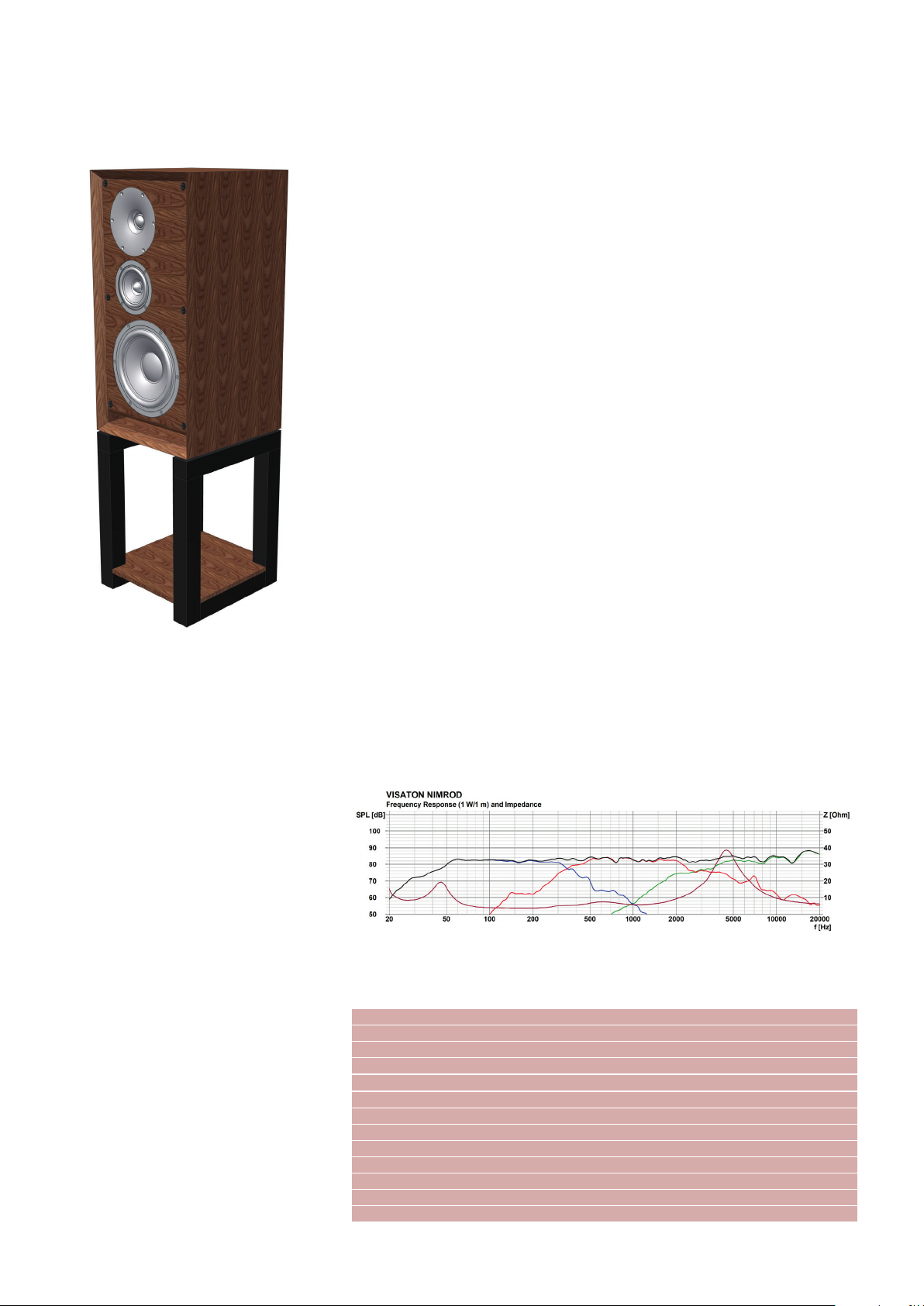
Nimrod
Eigenschaften und Klang
Gehen wir zurück in die 70er Jahre nach Großbritannien zur Entstehung der legendären
BBC Monitore und den größeren Lautsprechermodellen für zu Hause. In eine Zeit, in
der Musikhören noch mit guten alten Schallplatten stattfand und dementsprechend zelebriert wurde. Dieses Gefühl von früher wollten
wir mit der Nimrod wieder aufleben lassen.
Optisch war daher die Richtung klar vorgegeben. In Sachen Akustik wurde jedoch auf
moderne Chassis, wie z.B. den hochgelobten B 100 zurückgegriffen, um das bestmögliche Ergebnis zu erreichen. Hierzu dient auch
die mit einem Waveguide versehene Gewebe-Hochtonkalotte G 25 FFL, die akribisch an
die Abstrahlcharakteristik des B 100 angepasst wurde. Die außermittige Positionierung
der Mittel-/Hochtoneinheit optimiert nochmals
das Abstrahlverhalten und ist untypisch für
Lautsprecher dieser Gattung. Das Bassfundament und damit der so geschätzte warme
Klang der britischen Modelle wird durch den
GF 200 Tieftöner repräsentiert.
Wie kommt nun aber der Name Nimrod zu
Stande? Bei Nimrod handelt es sich um die
9. Variation des Orchesterwerkes „Enigma“
des britischen Komponisten Edward Elgar,
welche einem seiner engsten Freunde, dem
deutschen August Jaeger gewidmet wurde.
Es spiegelt die Geschichte von etwas wider,
was zwischen den beiden passiert ist. Ende des 19. Jahrhunderts war Elgar „im Herzen von Musik sehr krank“ und wollte das
Komponieren aufgeben. Sein Freund Jaeger
versuchte ihn aufzumuntern, indem er über
Ludwig van Beethoven sprach, der trotz vieler Sorgen immer faszinierende Musikstücke
schrieb. Dies führte zu den ersten Takten von
N
imrod
und dazu, dass Elgar weiter Musik
komponierte.
Diese Britisch-Deutsche Freundschaft durch
Musik war der Ausschlag zur Namensgebung
und zeigt auch unsere langjährige Verbundenheit zu britischen Kollegen und Freunden,
welche wir mit der N
Wie klingt nun die Nimrod? Im Grunde kann
man sie als die perfekte Britisch-Deutsche Mischung bezeichnen. Einerseits hat man den
warmen, raumfüllenden Klang der britischen
Lautsprecher aus vergangenen Zeiten, andererseits aber auch die hohe Präzision der
modernen deutschen Ingenieurskunst. Von
beiden nicht zu viel oder zu wenig.
imrod
schätzen möchten.
Nennbelastbarkeit Rated power 120 W
Musikbelastbarkeit Maximum power 180 W
Nennimpedanz Nominal impedance 4Ω
Übertragungsbereich Frequency response (–10 dB) 31–20
000 Hz
Mittl. Schalldruckpegel Mean sound pressure level 84 dB (1 W/1 m)
Trennfrequenz Cut-off frequency 350/3200 Hz
Gehäuseprinzip Principle of Housing Bassreflex
Gehäusemaße Cabinet
Nettovolumen Net volume 34,5 l + 1,5 l
Höhe Height 606 mm (1011 mm mit Fuß)
Breite Width 304 mm
Tiefe Depth 320 mm
HiFi Bauvorschläge 2020 1
Page 2
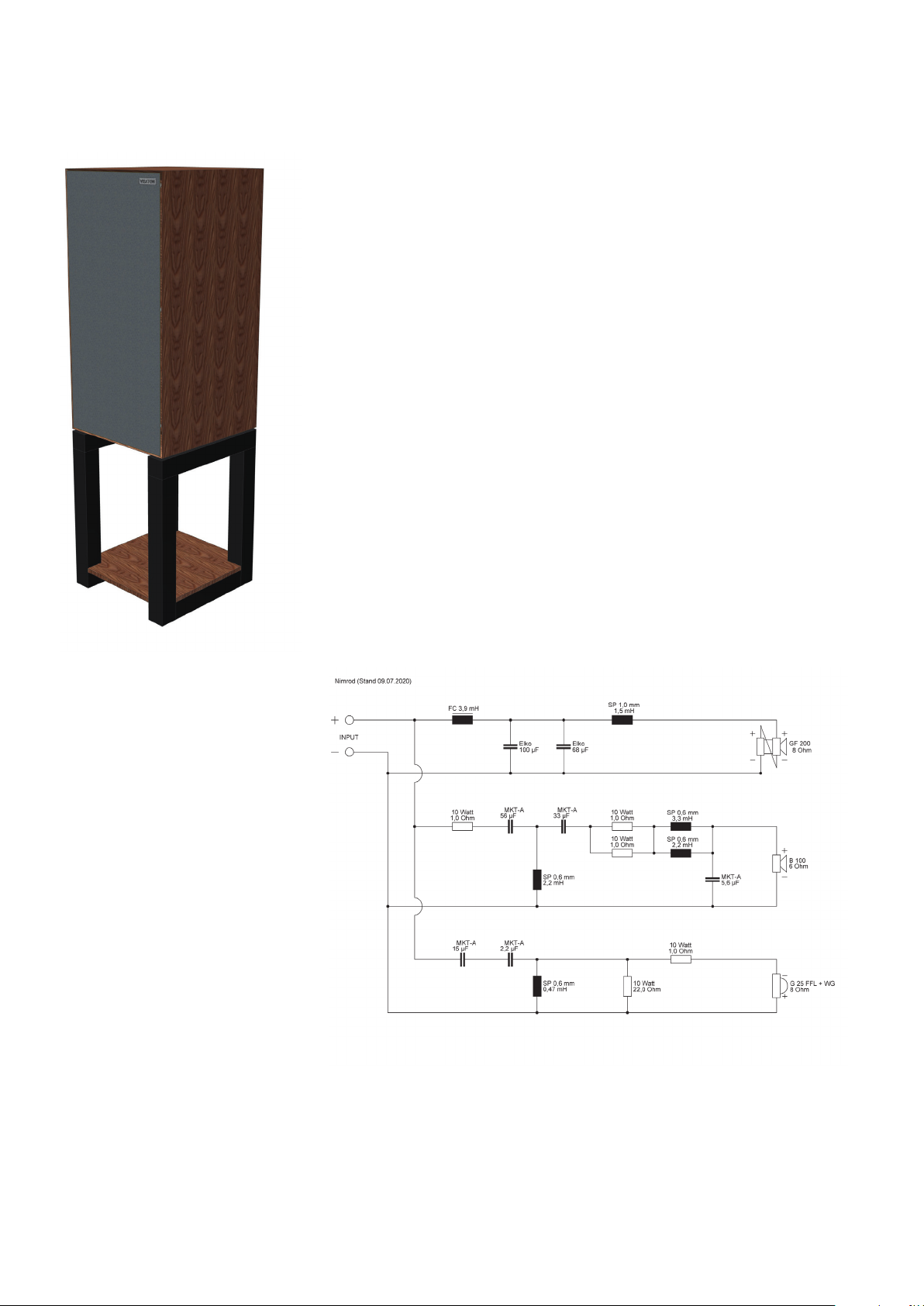
Nimrod
Characteristics and sound properties
Let's go back to the 1970s in the UK to the
creation of the legendary BBC monitors and
the larger speaker models for home use.
This was a time when listening to music still
involved good old vinyl records and was a
pleasure to be enjoyed. Our aim in producing
the Nimrod was to revive this feeling from the
past.
The visual appearance was, therefore, clearly
predefined. In terms of acoustics, however,
we have used such state-of-the-art drivers
as the highly praised B 100 to achieve
the best possible results. This is also the
reason why we opted for the G 25 FFL fabric
dome tweeter, equipped with a waveguide
and meticulously adapted to the radiation
characteristics of the B 100. The off-centre
positioning of the medium to high-frequency
unit further optimises the radiation pattern
and is unusual for loudspeakers of this type.
The bass foundation and with it the much
appreciated mellow aspect of the British
models is accounted for by the GF 200 woofer.
But how did the name N
N
imrod
is the 9th variation of the orchestral
work entitled "Enigma" by the British
composer Edward Elgar, which was dedicated
to one of his closest friends, the German
August Jaeger. The name is a play on words,
imrod
come about?
as the biblical Nimrod was a great hunter, and
the German word "Jaeger" means "hunter",
and reflects an episode that happened
between these two great friends. At the end
of the 19th century, Elgar was in a depressed
state, "very ill at heart with music", and was
considering giving up composing. His friend,
August Jaeger, tried to cheer him up by
reminding him that Ludwig van Beethoven,
despite serious worries, continued to write
fascinating pieces of music. This led to the
first bars of N
to compose music.
This British-German friendship through music
was the decisive factor in the naming of the
Nimrod and also shows our long-standing
connection to British colleagues and friends,
which we would like to celebrate with the
Nimrod.
What does the Nimrod sound like? One might
be tempted to describe it as the perfect
British-German combination. On the one
hand, you have the mellifluous, room-filling
sound of the British loudspeakers from times
gone by, but on the other hand, you also have
the high-grade precision of modern German
engineering. Not too much of either, but not
too little, either.
imrod
and to Elgar continuing
2 HiFi Bauvorschläge 2020
Page 3

Nimrod
Aufbau
Die Nimrod im vorgeschlagenen Design
kann nicht gerade als Anfängerbox bezeichnet werden und erfordert sehr präzises Arbeiten. Der Schwierigkeitsgrad ist
aufgrund der auf Gehrung geschnittenen
Wände und dem filigranen Bespannrahmen entsprechend hoch.
Des Weiteren müssen die Gehäuse spiegelsymmetrisch aufgebaut werden, was
vor allem bei der Frontwand und dem
Bespannrahmen, sowie beim Zusammenbau beachtet werden muss.
Wie bei allen Bausätzen sollte man sich
zu Beginn Gedanken über die spätere
Optik machen. Plant man z.B. das Gehäuse am Ende zu furnieren, müssen
entsprechende Materialstärken beim
Ausfräsen der Lautsprecheröffnungen
mit einberechnet werden.
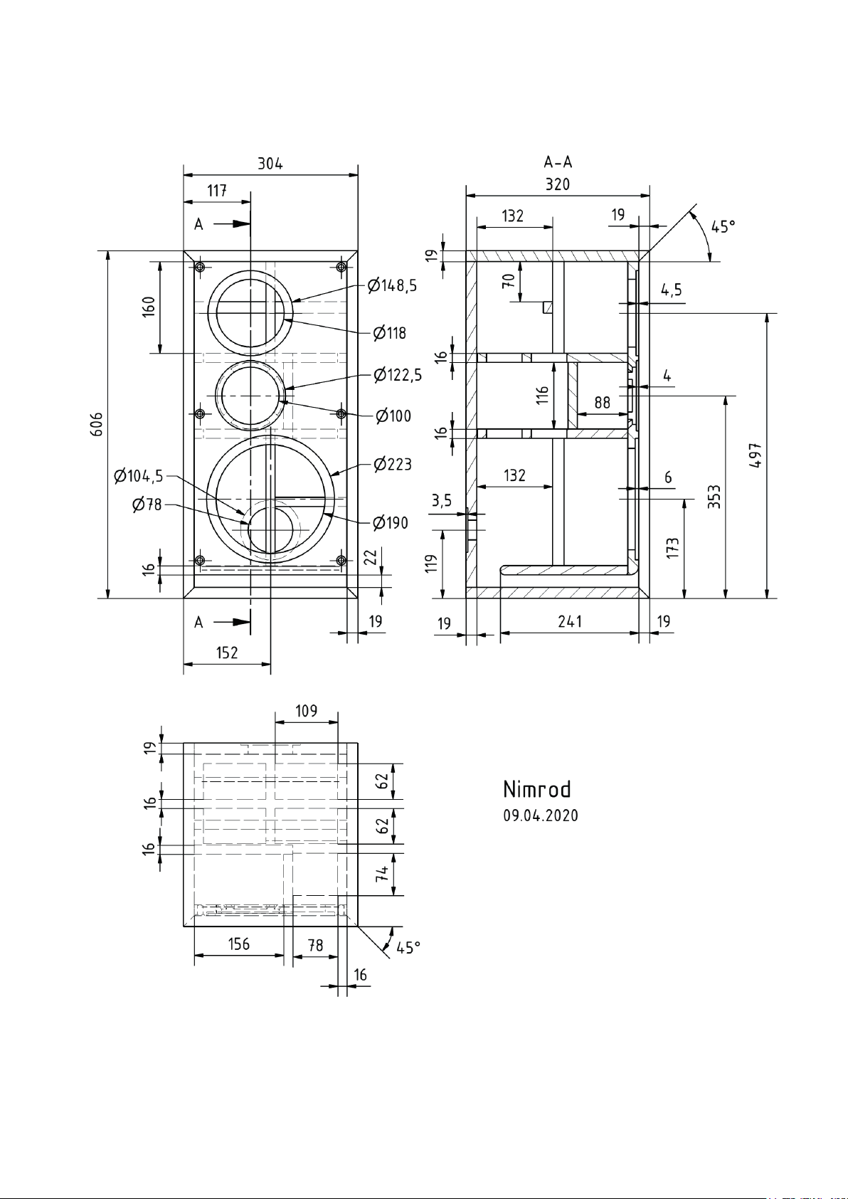
Anfangs werden alle Platten einzeln vorbereitet, deren Zeichnungen zur Fehlervermeidung und Vereinfachung separat in der Anleitung zu finden sind. Auf
diese Weise muss man nur jede Platte Stück für Stück gemäß der entsprechenden Maße bearbeiten und später
zusammenbauen.
Da der Deckel, der Boden und die beiden
Seiten auf Gehrung zugeschnitten werden sowie viele Fasen vorhanden sind,
ist eine präzise arbeitende Tischkreissäge von Vorteil. Die notwendigen 45° Fasen sind in den jeweiligen Zeichnungen
entsprechend dargestellt.
Neben den genauen Außenmaßen sind
u.a. folgende Punkte bei den entsprechenden Einzelplatten wichtig:
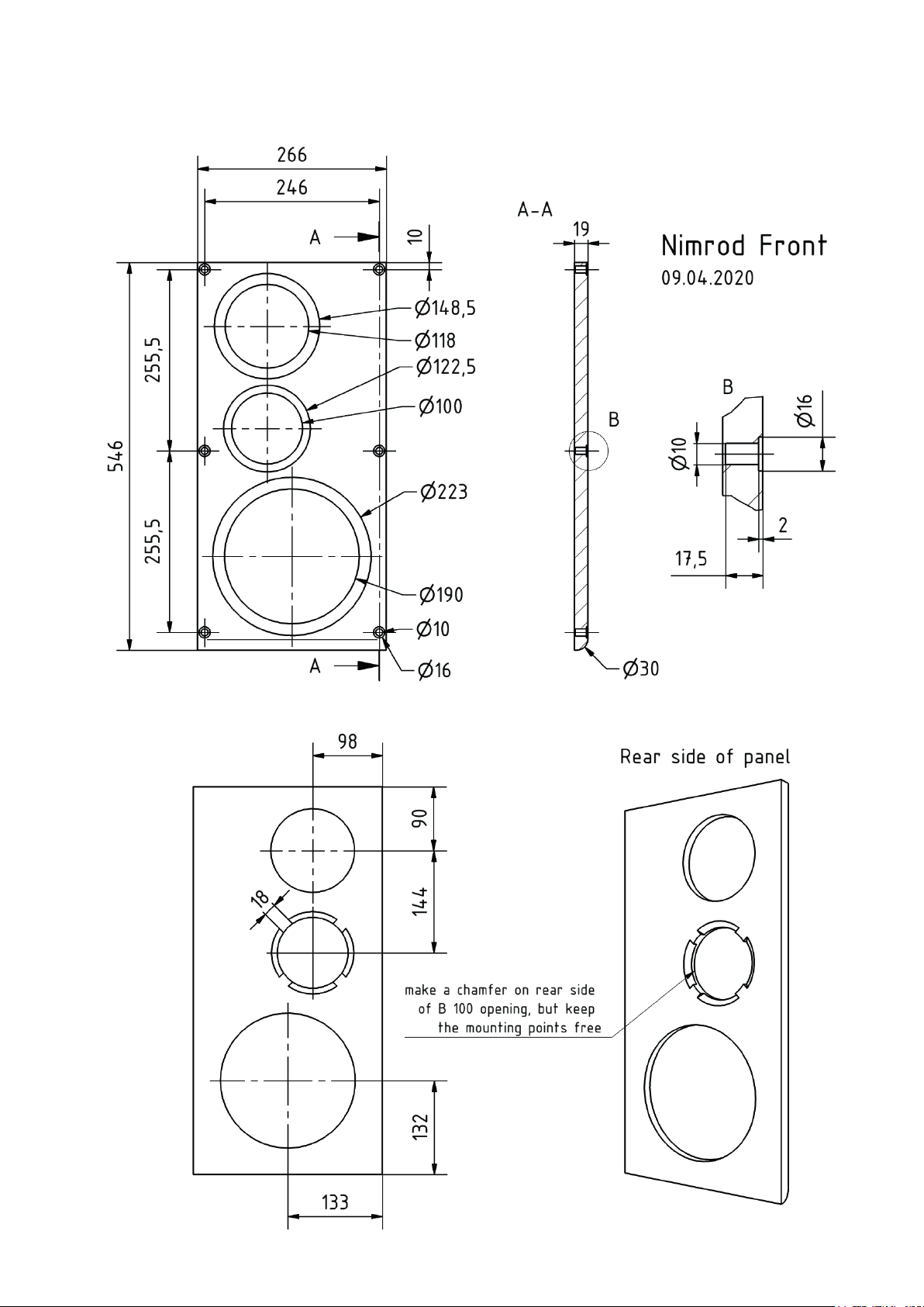
Front:
- Am unteren Ende muss der Übergang zum Bassreflexkanal abgerundet werden (R = 15 mm).
- Der Ausschnitt des B 100 Lautsprechers muss rückseitig mit einer Fase versehen werden, da sonst die
rückseitigen Öffnungen im Korb des
Lautsprechers zu stark von der Frontwand verdeckt wären. Eine 45° Fase mit ca. 8 mm Tiefe genügt dabei.
Um ausreichend Material für eine gute Befestigung des Lautsprechers zu
haben, empfiehlt es sich, an den vier
Schraubenpositionen keine Fase anzubringen.
- Der Bespannrahmen wird später mit
Rahmendübeln an der Front befes-
tigt. Da diese sehr nah am Rand der
Frontplatte liegen, empfiehlt es sich,
sie nur mit einem kleinen Bohrer vorzubohren, um die genaue Position zu
erhalten und sie erst nach dem Zusammenbau in den finalen Zustand
zu bringen. Damit der Rahmen später exakt sitzt, ist eine präzise Position der Löcher für die Rahmendübel
essentiell.
Bassreflex-Brett:
- Das Bassreflex-Brett erhält einseitig eine Rundung, welche die Strömungseigenschaften verbessert und
hörbare Störungen vermeidet.
Versteifungsbretter:
- Die beiden Versteifungsbretter haben jeweils fünf Öffnungen. Es empfiehlt sich also, die Öffnungen entsprechend mit einem Bleistift zu markieren und danach auszusägen.
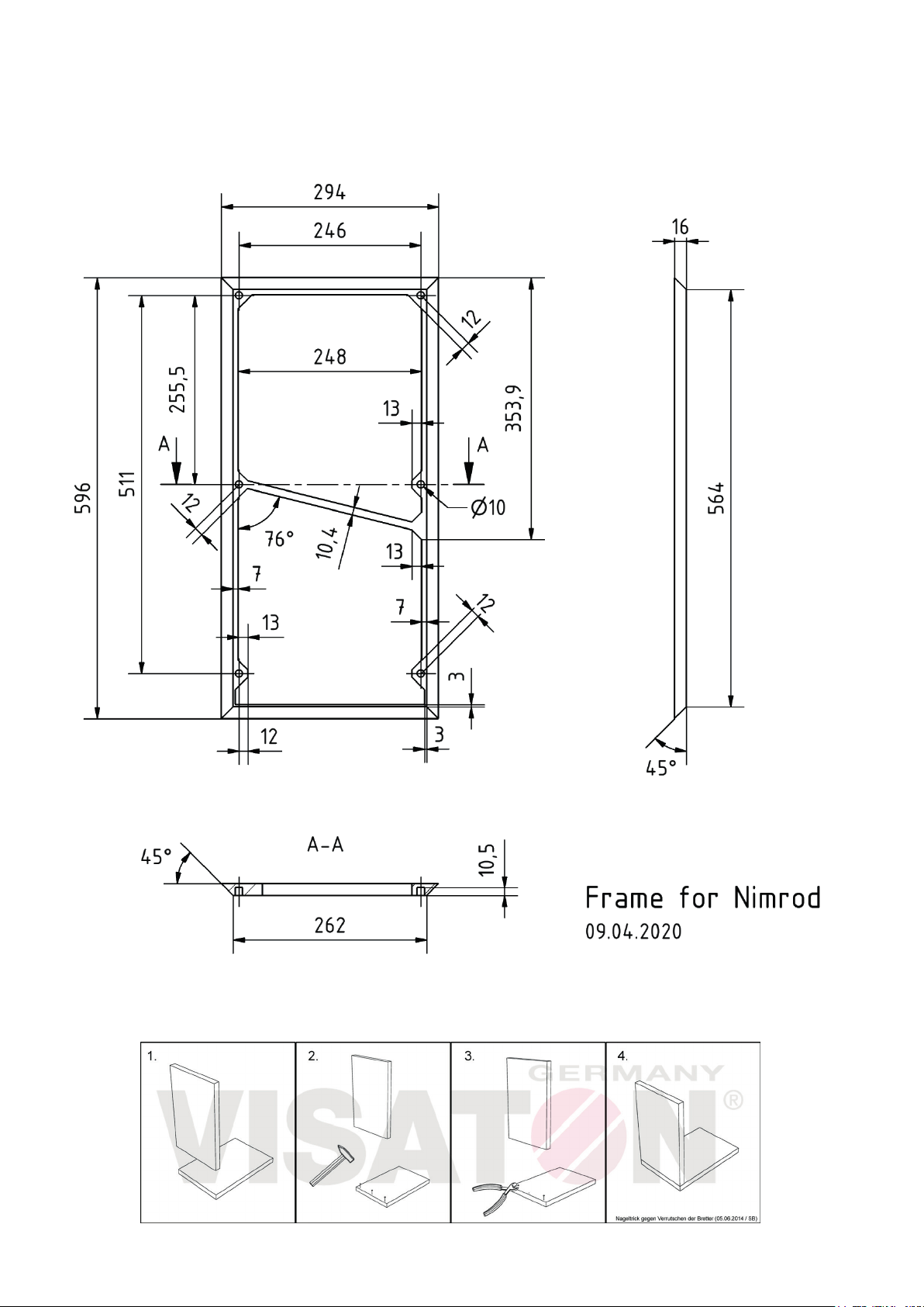
Bespannrahmen:
- Der Rahmen ist sehr filigran aufgebaut. Daher beginnt man am besten
mit den vier äußeren 45° Fasen.
- Anschließend legt man die Frontwand mittig auf den Bespannrahmen und kopiert die Löcher der Rahmendübel, welche so im Anschluss
auf das richtige Maß gebohrt werden
können.
-
Zum Schluss erfolgt das Aussägen
der beiden großen Flächen im Inneren. Hierbei ist vor allem im unteren
Bereich sowie an der mittleren Strebe Vorsicht geboten, da diese sehr
dünn sind und leicht brechen können.
- Die beiden freigesägten Platten können
genutzt werden, um daraus die vier 20
mm breiten Verstrebungen zu fertigen
Nach Vorbereitung der einzelnen Platten
kommt nun der Trockenaufbau. Hierbei
sollten die Platten so gut wie möglich zusammengeführt werden. Ggf. kann man
die vier äußeren Platten (Boden, Deckel
und Seitenwände) mit einfachem und
leicht zu lösendem Klebeband fixieren.
Passen alle Platten gut zusammen, positioniert man probehalber die Frequenzweiche im unteren Bereich des Gehäuses (Zuleitung zur Anschlussklemme
nach unten). Hierfür wurde an der einen
Seitenwand die Verstrebung weggelassen. Dort kann die Befestigungsposition markiert werden, was den späteren
Einbau der Frequenzweiche erleichtert
(Ausrichtung der Weiche so, dass die
Zuleitung zur Anschlussklemme nach
unten führt).
Nach dem Trockenaufbau können die
Platten wieder auseinandergenommen
werden und die Befestigungslöcher der
Frequenzweiche vorgebohrt werden
(2,5 mm Bohrer). Dabei gilt: Nur vorbohren, nicht durchbohren!
Nun folgt der finale Zusammenbau. Am
sinnvollsten beginnt man mit den beiden
Versteifungsbrettern (mit den fünf Öffnungen) und den Wänden für das Mitteltongehäuse, da diese einfach auf Stoß
miteinander verleimt werden (siehe auch
„Schritt 1“ in der Montagehilfe). Ein Verrutschen der Platten kann durch den bekannten Nageltrick vermieden werden.
Hierfür werden dünne Nägel in die Platten geschlagen und mit einem robusten
Seitenschneider abgeknipst (siehe auch
die Erklärung dazu). Mittels Schraubzwingen kann dann dieses Konstrukt in
Form gehalten werden und etwas antrocknen.
Wie bei allen Verbindungen auf Stoß
ist es wichtig, dass die Platten perfekt
rechtwinklig angebracht sind. Hierbei
hilft ein 90° Winkel zur Überprüfung.
In der Zwischenzeit kann man mit dem
Verleimen der Rückwand mit einer Seitenwand und dem Boden fortfahren.
Zur Vereinfachung legt man zuerst einen Streifen Klebeband auf den Tisch
(Klebeseite nach oben, Länge etwas
mehr als die Box breit ist) und positi
oniert die Seitenplatte darauf so, dass
die Kante zur Bodenplatte das Klebeband zur Hälfte abdeckt. Danach platziert man die Bodenplatte direkt daneben
flach auf dem Klebeband, welches später als provisorisches Scharnier dienen
soll. Im nächsten Schritt zieht man eine
Spur aus Leim an den beiden Seiten der
Rückwand und klebt diese auf die Seitenplatte. Danach folgt Leim in der Gehrungskante von Seitenwand und Boden
und man kann die Bodenplatte hoch-
-
HiFi Bauvorschläge 2020 3
Page 4

Nimrod
klappen und mit der Rückwand verbinden (siehe auch „Schritt 2“ in der Montagehilfe). Anschließend werden die obere
horizontale Verstrebung und das Bassreflexbrett angebracht (siehe auch „Schritt
3“ in der Montagehilfe).
Nach diesem Schritt ist die Einheit aus
Versteifungsbrettern und Mitteltongehäuse gut genug angetrocknet, um auf
der Seitenwand und mit der Rückwand
verleimt zu werden. Wichtig ist dabei die
Ausrichtung des Mitteltongehäuses passend zur Öffnung in der Frontwand (linke
Box ist spiegelsymmetrisch zur rechten
Box). Danach können die fehlenden Verstrebungen, sowie die Frontwand angebracht werden (siehe auch „Schritt 4“ in
der Montagehilfe).
Auch der Deckel kann nun angebracht
werden. Um den Übergang an der Gehrung sauber zu verarbeiten, sollte man
auch hier wieder mit Klebeband ein provisorisches Scharnier anfertigen (siehe
auch „Schritt 5“ in der Montagehilfe).
Anschließend kann man alle inneren Kanten nochmal mit einer Spur aus Leim versehen, welcher mit dem Finger glatt gestriffen wird.
Zum Schluss folgt die fehlende Seitenwand, welche wieder mit Klebeband fixiert wird (siehe auch „Schritt 6“ in der
Montagehilfe). Dabei wichtig ist, dass
auch die inneren Stoßkanten der anderen Platten (wie die beiden Versteifungsplatten, die beiden Verstrebungen, sowie der Bassreflexkanal), ebenfalls mit
Leim versehen werden.
Nach einer ausreichenden Trocknungsphase können die provisorischen Klebebänder, sowie andere Hilfsmittel (z.B.
Schraubzwingen) entfernt werden und
man kann mit den Löchern für die Rahmendübel weitermachen. Danach wird
ein Loch für die Zuleitung zum Mitteltöner gebohrt. Hierfür wird einfach ein 6-8
mm Loch durch die Öffnung des Lautsprechers in die Trennwand gebohrt.
Auf der Zielgeraden des Gehäusebaus
müssen nur noch die Schraubpunkte der
Lautsprecher, des Waveguides und der
Anschlussklemme mit einem 2,5 mm
Bohrer vorgebohrt werden. Das eigentliche Gehäuse ist damit fertig für finalen
Verschönerungen.
Ist während den Trocknungsphasen Zeit,
kann man diese sinnvoll mit dem Bau des
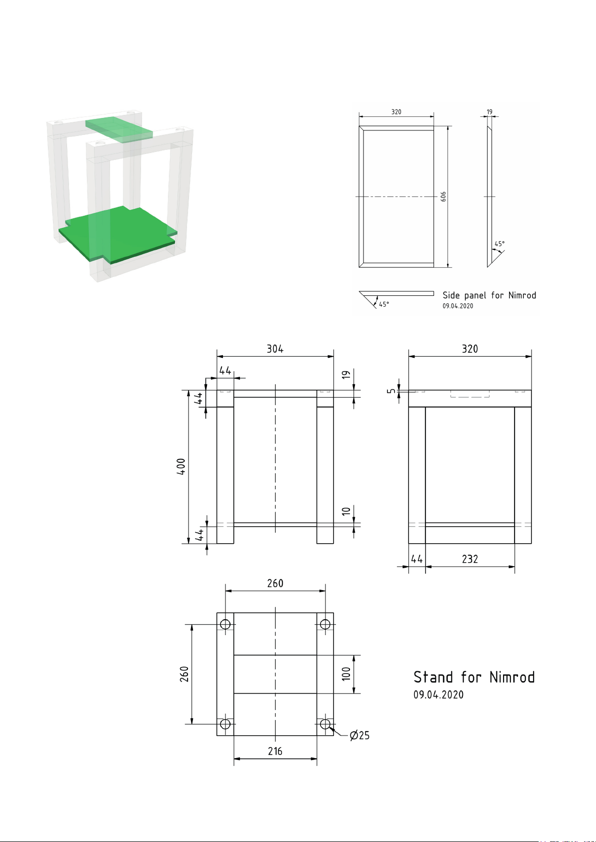
Ständers nutzen. Dieser besteht aus 8
Kanthölzern (44 x 44 mm), welche man
sich im Baumarkt bereits auf die richtige Länge sägen lassen kann. Sie werden einfach auf Stoß verleimt. Sofern
man die Möglichkeit einer Holz-Dübelfräse hat, können die Kanthölzer auch entsprechend mit Dübeln verbunden werden. Die beiden Zwischenbretter werden
entsprechend der Zeichnung ausgesägt
und mit den Kanthölzern verleimt.
Zum Schluss bohrt man mit einem Forstnerbohrer vier Aufnahmen für die Boxenfüße in die oberen Kanthölzer.
Die Boxenfüße selbst kann man z.B. mit
einer Lochkreissäge aussägen. Sie werden später an entsprechender Stelle mit
dem Lautsprechergehäuse verbunden
(verschraubt oder geklebt) und dienen
einem stabileren Stand auf dem Ständer.
Nachdem das Gehäuse und der Ständer ihr finales Finish bekommen haben,
von Staub gereinigt wurden und der Bespannrahmen lackiert wurde, kann der
Bespannstoff angebracht werden. Hierfür gibt es mehrere Möglichkeiten, wobei wir zwei davon vorstellen möchten:
1) Heißkleber und altes Bügeleisen:
Hierbei handelt es sich um unser favorisiertes Verfahren, da es einfach umzusetzen ist und ein sauberes Ergebnis liefert.
Zunächst platziert man den Bespann
rahmen vor sich auf einem Tisch mit der
Rückseite nach oben. Auf der Rückseite
wird nun eine Spur mit Heißkleber gezogen (siehe auch „Schritt 7“ in der Montageanleitung). Nachdem dieser getrocknet ist, wird der Bespannrahmen mit der
Sichtseite auf den Bespannstoff gelegt
und eine Seite des Stoffs über den Rahmen gezogen (z.B. über die lange Seite).
Nun nimmt man das heiße Bügeleisen
(Baumwollstufe genügt) und fährt über
den Bespannstoff, unter dem der Heißkleber aufgebracht wurde (siehe auch
„Schritt 8“ in der Montageanleitung). Der
Heißkleber schmilzt und verbindet sich
mit den Fasern des Bespannstoffs. Gegebenenfalls kann man ein Stück Papier
zwischen Bügeleisen und Bespannstoff
legen, falls das Bügeleisen zu heiß sein
sollte. Ist eine Seite des Bespannstoffs
am Rahmen fixiert, zieht man den Stoff
stramm zur anderen parallel liegenden
Seite und befestigt ihn dort auf die gleiche Weise. Danach folgen die beiden anderen Seiten. Zum Schluss und bei Bedarf auch während der Arbeitsschritte,
wird das überstehende Material mit einer Schere/einem scharfen Messer abgeschnitten.
2) Tacker:
Der Bespannstoff kann auch rückseitig
mittels Tacker mit dem Rahmen befestigt werden. Allerdings muss man hier
äußerst vorsichtig arbeiten, da sonst der
Tacker den filigranen Rahmen zerstören kann.
Danach werden die Rahmendübel im Bespannrahmen und der Frontwand befestigt. Hat man exakt gebohrt, müssen die
Rahmendübel nachträglich nicht verklebt
werden. Zum Einschlagen der Pins in
den Bespannrahmen mit einem Hammer,
stülpt man eine Hülse der Rahmendübel
darüber und schützt damit den Pin vor
dem abbrechen (siehe auch „Schritt 9
und 10“ in der Montageanleitung).
Abschließend folgt das Bestücken des
Gehäuses beginnend mit der Frequenzweiche. Diese wird entsprechend des
beigefügten Anschlussplans vorbereitet
und mit Kabeln versehen. Danach kann
sie an der bereits angezeichneten und
vorgebohrten Stelle an der Seitenwand
im Gehäuse befestigt werden (mit der
Zuleitung zur Anschlussklemme nach unten ausgerichtet). Die Kabel werden nun
locker zu den jeweiligen Öffnungen in
der Frontwand gelegt, so dass sie noch
ca. 10 cm aus dem Gehäuse ragen. Im
nächsten Schritt wird die Kabeldurch-
-
führung im Mitteltongehäuse mit Heißkleber abgedichtet.
Es folgt die Bedämpfung des Gehäuses
laut Bedämpfungsplan.
Zum Schluss können die Lautsprecher
angelötet und mit dem Gehäuse verschraubt werden. Dabei muss Folgendes beachtet werden:
Wurden die Fräsungen in der Frontwand
sauber ausgeführt und die Oberflächen
zeigen keine Wellen, ist auch kein Dichtband zwischen Lautsprecher und Gehäuse notwendig. Ist dies nicht der Fall,
kann z.B. dünnes Fensterdichtband aus
dem Baumarkt genutzt werden.
Für die Verbindung des Hochtöners
G 25 FFL mit dem Waveguide WG 148 R
sind dem Waveguide Schrauben beigefügt. Als Dichtung dazwischen kann der
Schaumstoffschutz der G 25 FFL Verpackung genutzt werden.
4 HiFi Bauvorschläge 2020
Page 5

Nimrod
Building instructions
The present design of the Nimrod could
not by any means be termed a beginner's
cabinet and requires very precise work.
It is the mitre-cut walls and the filigree
grille frame that make it a particularly
demanding project.
In addition, the cabinets have to be built
as symmetrical mirror images of each
other, which must be taken into account,
especially when it comes to the front
baffle and the frame, but also during the
assembly process as a whole.
As with all kits, it is imperative right from
the start to bear in mind the subsequent
appearance. If, for example, you intend
to veneer the outside surfaces at the
end, the additional material thickness
will have to be taken into account when
routing the loudspeaker openings.
Initially, all the panels are individually
prepared – drawings of the individual
panels can be found in the manual
to simplify the process and assist in
error prevention. In this way, it is only
necessary to cut the panels one at a
time to the dimensions given and then
assemble them later.
Since the lid, bottom and both sides are
mitred and there are several chamfers,
a very accurate circular table saw
is advantageous. The 45° chamfers
required are shown accordingly in the
respective drawings.
In addition to the exact external
dimensions, the following points are
crucial with respect to the corresponding
individual panels:
Front panel:
- At the bottom end, the transition to
the bass reflex tube must be rounded
off (r = 15 mm).
- The rear of the cut-out for the B 100
loudspeaker must be chamfered,
otherwise the rear openings in the
loudspeaker basket will be covered
too much by the front baffle. A 45°
chamfer with a depth of approx.
8 mm is sufficient. In order to make
sure there is enough material for
the speaker to be firmly mounted
we recommend you do not apply
chamfers at the four screw positions.
- The grille frame is fixed to the cabinet
using wooden frame dowels later. As
these are very close to the edge of
the front panel, it is advisable to predrill them only with a small drill bit to
obtain the exact position and finish
them to the right size after assembly.
To ensure that the frame fits exactly
later, it is essential that the holes for
the frame dowels are positioned very
accurately.
Bass reflex panel:
- The bass reflex panel is rounded off
on one side, which improves the flow
characteristics and prevents audible
interference.
Bracing boards:
- The two bracing boards each have
five cut-outs. It is advisable to mark
the openings accordingly with a
pencil and then cut them out.
Grille frame:
- The grille frame is a very filigree
structure. It is therefore best to start
with the four outer 45° chamfers.
- Then place the front baffle centrally on
the frame and copy the holes for the
frame dowels, which can be drilled
to the correct size subsequently.
- Finally, cut out the two inner sections,
while being extremely careful
especially in the lower section and
around the centre strut, as these are
very thin and can break easily.
- The two cut-away sections can now
be used to make the four 20 mm wide
bracing struts.
Now that the individual panels have been
cut to size and prepared, we can do a dry
run to check fitting. The panels should be
fitted together as tightly as possible. It is
also possible to fix the four outer panels
(bottom, lid and side walls) with simple
adhesive tape that is easy to remove. If all
the panels fit together well, the crossover
unit should be positioned in the lower
part of the cabinet (the wires leading to
the terminal should face downwards).
To this end, the bracing on one side wall
has been omitted. The mounting position
can be marked here, which will facilitate
subsequent installation of the crossover
(align the crossover so that the supply
wires to the terminal are facing down).
After this dry assembly stage, the
panels can be taken apart again and the
mounting holes of the crossover unit predrilled (2.5 mm drill). Note: only pre-drill
the holes, they must not go right through.
Now we can begin final assembly. It is
best to start with the two bracing boards
(with the five cut-outs) and the partitions
for the mid-range enclosure, as these are
simply butt-glued together (see Step 1 in
the assembly illustrations). It is possible
to prevent the panels slipping out of
position by applying the “nail trick".
This involves hammering thin tacks
into the panels and then cutting off the
heads with robust side cutters (see the
explanation on this). Use sash cramps to
keep the assembly in shape while it dries.
As with all butt joints, it is crucial that
the panels are perfectly perpendicular to
each other – use a 90° engineer's square
to ensure this is the case.
In the meantime, you can continue by
gluing the back wall to a side wall and the
base. To make things easier, place a strip
of adhesive tape on the table (adhesive
side up, length slightly more than the
width of the cabinet) and position the
side panel on it so that the edge that
will mate with the base covers half of the
width of the adhesive tape. Then place
the base directly opposite it flat on the
adhesive tape, which will later serve as
a temporary hinge. The next step is to
apply a bead of glue on both sides of the
back panel and glue it to the side panel.
Then apply glue to the mitre edges of
the side panel and base and fold up the
base so that it connects to the rear panel
(see Step 2 in the assembly illustrations).
Next, attach the upper horizontal bracing
strut and the bass reflex board (see
Step 3 in the assembly illustrations).
After this step, the assembly consisting
of the bracing boards and mid-range
enclosure will have dried sufficiently to
be glued to the side and rear panels. It is
important that the mid-range enclosure
is aligned with the opening in the front
baffle (remember that the left speaker
is symmetrical to but a mirror image of
the right speaker). Next, fit the remaining
bracing struts and the front baffle (see
Step 4 in the assembly illustrations).
Finally glue the lid in place. In order to
ensure a clean finish on the mitred edges,
it makes sense to apply a temporary
hinge again using adhesive tape (see
Step 5 in the assembly illustrations).
Afterwards you can apply a bead of glue
to all the inner edges again and smooth
it using your finger.
HiFi Bauvorschläge 2020 5
Page 6

Nimrod
After allowing sufficient time for thorough
drying, you can remove the temporary
adhesive tapes and other aids (e.g. sash
cramps) and you can continue by drilling
the holes for the dowels. After that, a hole
is drilled for the feed wire to the midrange loudspeaker driver. To do so, drill
a 6-8 mm hole through the cut-out for
the speaker into the partition wall. In the
final phase of cabinet construction, all
we need to do now is pre-drill the fixing
points for the loudspeaker drivers, the
waveguide and the terminal with a 2.5
mm drill. The actual cabinet is now ready
for the final embellishments.
The time during the drying phases can
be used for the construction of the stand.
The stands consist of 8 square timbers
eachs (44 x 44 mm), which can be cut
to the right length in the DIY store. They
are simply glued together as butt joints.
If you have access to a dowel jointer, the
square timbers can also be connected
with dowels. The two intermediate
boards are cut out as shown in the
drawing and glued to the square timbers.
Finally, drill four mounts for the cabinet
feet in the upper square timbers using
a pattern maker's bit.
The cabinet feet themselves can be
made using a hole saw, for example.
They are later attached (screwed or
glued) to the loudspeaker cabinet at the
appropriate places and will provide more
stable positioning on the stand.
After the cabinet and the stand have been
given their final finish, cleaned from dust
and the grille frame has been painted,
the fabric material can be applied. There
are a number of ways to do this and we
will now demonstrate two.
the fabric. If the iron is too hot, place a
piece of paper between the iron and the
fabric. As soon as one side of the fabric
is firmly attached to the frame, pull the
fabric tightly to the other parallel side and
fix it there in the same way. Then repeat
the procedure for the other two sides.
Finally, and if necessary during the work
steps, the excess material is cut off with
scissors or a sharp knife.
2) Staple gun:
The fabric can also be firmly attached to
the back of the frame using a staple gun.
However, it is very important to work very
carefully here, as otherwise the staple
gun can destroy the filigree frame.
Now the dowels can be fixed in the frame
and the front baffle. If the holes have been
drilled very accurately, the dowels will not
have to be glued afterwards. To tap the
pins into the frame with a hammer, put a
dowel sleeve over them first to prevent
the pin breaking off (see Steps 9 and 10
in the assembly illustrations).
To complete the assembly process, we
will now fit the technical items, beginning
with the crossover. This item has to be
prepared according to the attached
connection diagram and fitted with
wires. It can then be attached to the
marked and pre-drilled location on the
side wall of the cabinet (with the leads
to the terminal pointing downwards).
The wires to the respective openings
in the front wall are now laid loosely so
that they protrude approx. 10 cm from
the cabinet. The next step is to seal off
the cable lead-through in the mid-range
enclosure with hot-melt glue.
Next, the cabinet is damped on the
inside as shown in the diagram.
can be used as a seal between the
waveguide and the tweeter.
Inner damping
To ensure even damping, ¼ of a mat is
cut with scissors and loosely placed in
the mid-range enclosure. The remaining
3 ¾ mats are inserted into the cabinet
through the woofer and tweeter cut-outs
and distributed loosely but evenly. It is
important that the mats do not clog the
bass reflex port and that they are really
loose inside the cabinet. Damping on the
walls is wrong and reduces the effect.
Components list for one cabinet
The kit includes all the components listed
here but not the cabinet.
Woofer GF 200 1 off
Mid-range B 100 1 off
Waveguide WG 148 R 1 off
Dome tweeter G 25 FFL 1 off
Crossover
Terminal ST77 1 off
Damping polyester
material wool 2 bags
Screws
Countersunk 3.5 x 25 mm 10 off
(terminal & waveguide)
Screws
(cheesehead) 4 x 25 mm 4 off
(B 100)
Screws
(cheesehead) 5 x 30 mm 6 screws
(GF 200)
Cables 2 x 1.5 mm² 2 m
Fabric 50 cm
(black) 0.8 m
Dowels 6 off
Nimrod 1 off
1) Hot-melt glue and an old iron:
This is our preferred method because
it is easy to implement and produces
clean results. First of all, place the frame
in front of you on a table with the rear
facing upwards. Now apply a bead of
hot-melt glue all along the back (see
Step 7 in the assembly illustrations). After
it has hardened, place the front side of
the frame on the covering fabric and lift
one side of the fabric over the frame (e.g.
one of the long sides). Now apply the hot
iron (the "cotton" setting is hot enough)
and run it over the fabric under which
the hot glue was applied (see Step 8 in
the assembly illustrations). The hot melt
glue will melt and bond with the fibres of
6 HiFi Bauvorschläge 2020
Finally, the speaker wires can be soldered
in place and the speakers screwed to the
housing. In this respect, please note the
following points:
If the milled cut-outs in the front wall
are clean and the surfaces do not show
any wavy edges, no sealing tape will be
required between the speakers and the
cabinet. If there are wavy edges, thin
window sealing tape from the DIY store
can be used.
Screws have been included with the
waveguide WG 148 R for attaching it to
the G 25 FFL tweeter. The foam used as
protection in the G 25 FFL packaging
Page 7

Nimrod
Bedämpfung
Für eine gleichmäßige Bedämpfung wird
¼ einer Matte mit einer Schere ausgeschnitten und locker im Mitteltongehäuse platziert. Die restlichen 3 ¾ Matten
werden durch den Tieftöner- und Hochtönerausschnitt in das Gehäuse gebracht
und dort ebenfalls locker und gleichmäßig verteilt. Wichtig ist, dass die Matten nicht den Bassreflexkanal verstopfen und auch wirklich locker im Inneren
des Gehäuses liegen. Eine Bedämpfung
an den Wänden ist falsch und reduziert
die Wirkung.
Bestückungsliste für 1 Box
Der Bausatz enthält alle in dieser Bestückungsliste aufgeführten Bauteile, jedoch kein Gehäuse.
Tieftöner GF 200 1 St.
Mitteltöner B 100 1 St.
Hochtöner G 25 FFL 1 St.
Waveguide WG 148 R 1 St.
Frequenzweiche
Terminal ST77 1 St.
Dämpfungs- Polyester
material wolle 2 Btl.
Schrauben
(Senkkopf) 3,5 x 25 mm 10 St.
(Terminal + WG)
Schrauben
(Zylinderkopf) 4 x 25 mm 4 St.
(B 100)
Schrauben
(Zylinderkopf) 5 x 30 mm 6 St.
(GF 200)
Kabel 2 x 1,5 mm² 2 m
Bespannstoff 50 cm
(schwarz) 0,8 m
Rahmendübel 6 St.
Nimrod 1 St.
Zuschnittliste für 1 Box
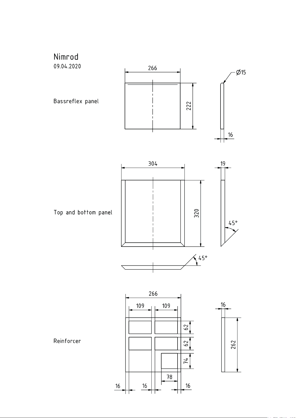
Hinweis: Alle Maße sind Außenmaße.
Gehrungen und Schrägen sind noch
abzusägen!
Teile Maße (mm) Anzahl
Material: 19 mm Spanplatte oder MDF
Front 266 x 546 mm 1
Deckel und
Boden 304 x 320 mm 2
Seiten 606 x 320 mm 2
Rückwand 266 x 568 mm 1
Teile Maße (mm) Anzahl
Material: 16 mm Spanplatte oder MDF
Bassreflexbrett 266 x 222 mm 1
Rückwand für Mitteltongehäuse 116 x 172 mm 1
Seitenwand für Mitteltongehäuse 116 x 88 mm 1
Versteifungsbrett 266 x 262 mm 2
Verstrebung oben
horizontal* 20 x 266 mm 1
Verstrebung oben
vertikal* 20 x 160 mm 1
Verstrebung unten
horizontal* 20 x 125 mm 1
Verstrebung unten
vertikal* 20 x 222 mm 1
Bespannrahmen 294 x 596 mm 1
*) die Verstrebungen können aus den freigesägten Bereichen des Bespannrahmen gefertigt werden
Zuschnittliste für 1 Standfuß
Teile Maße (mm) Anzahl
Material: 19 mm Spanplatte oder MDF
Strebe 216 x 100 mm 1
Parts list for one cabinet
Note: all dimensions are gross external
dimensions. Bevels and mitres are cut
from these.
Parts Dims. (mm) Qty
Material: 19 mm plywood or MDF
Front 266 x 546 mm 1
Lid &
base 304 x 320 mm 2
Sides 606 x 320 mm 2
Rear wall 266 x 568 mm 1
Parts Dims. (mm) Qty
Material: 16 mm plywood or MDF
Bass reflex board 266 x 222 mm 1
Rear wall for midrange enclosure 116 x 172 mm 1
Side wall for midrange enclosure 116 x 88 mm 1
Bracing
board 266 x 262 mm 2
Upper bracing strut
horizontal* 20 x 266 mm 1
Upper bracing strut
vertical* 20 x 160 mm 1
Bottom bracing strut
horizontal* 20 x 125 mm 1
Bottom bracing strut
vertical* 20 x 222 mm 1
Grille
frame 294 x 596 mm 1
*) the struts can be made from the cutout sections of the grille frame
Parts list for one stand
Parts Dims. (mm) Qty
Material: 19 mm plywood or MDF
Brace 216 x 100 mm 1
Material: 10 mm Spanplatte oder MDF
Bodenplatte 304 x 320 mm 1
Abstandshalter
für Box Ø 25 mm 4
Material: 44 x 44 mm Kantholz
Oben L = 320 mm 2
Seiten L = 356 mm 4
Unten L = 232 mm 2
Kabellängen:
Terminal – Weiche 380 mm
Weiche – Tieftöner 390 mm
Brücke Tieftöner 300 mm
Weiche – Mitteltöner 390 mm
Weiche – Hochtöner 540 mm
HiFi Bauvorschläge 2020 7
Material: 10 mm plywood or MDF
Base 304 x 320 mm 1
Spacer
for cabinet Ø 25 mm 4
Material: 44 x 44 mm square timber
Top L = 320 mm 2
Sides L = 356 mm 4
Bottom L = 232 mm 2
Cable lengths:
Terminal – crossover 380 mm
Crossover – woofer 390 mm
Woofer bridge 300 mm
Crossover – mid-range 390 mm
Crossover – tweeter 540 mm
Page 8
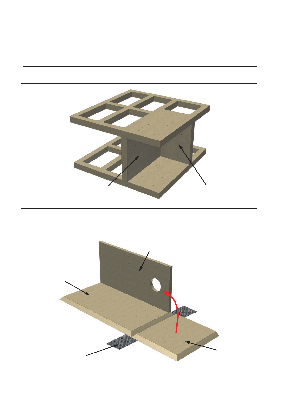
Schritt 1: Aufbau des Mitteltongehäuses
Step 1: Assembling the midrange enclosure
Schritt 2: Zusammenbau von Seitenwand, Rückwand und Bodenplatte
Step 2: Assembling side panel, rear panel and bottom panel
Versteifungsbretter
Rückwand für Mitteltongehäuse
Seitenwand für Mitteltongehäuse
Rückwand
Seitenwand
Bodenplatte
Klebeband
Nach oben klappen
Nimrod
Montagehilfe zum Bausatz Nimrod
Assembly guide for speaker kit Nimrod
Reinforcement panels
Rear panel for midrange enclosure
Side panel
Side panel for midrange enclosure
Rear panel
Fold up
Adhesive tape
8 HiFi Bauvorschläge 2020
Bottom panel
Page 9
Nimrod
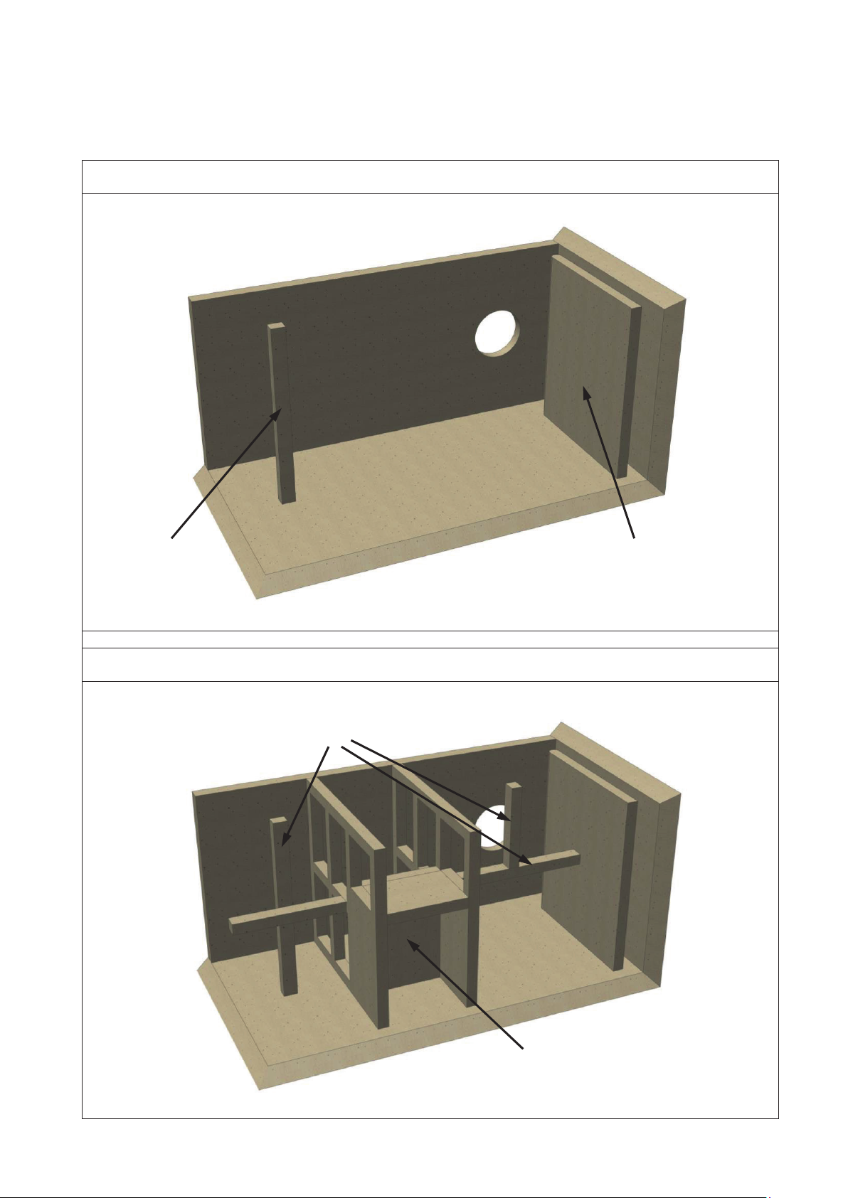
Schritt 3: Platzieren von Bassreflexbrett und obere horizontale Verstrebung
Step 3: Arrangement of bassreflex panel and top horizontal bracing strut
Schritt 4: Einsetzen des Mitteltongehäuses und Vervollständigung der Verstrebungen
Step 4: Insert the midrange enclosure and complete the bracing struts
Bassreflexbrett
Verstrebung
Verstrebungen
Mitteltongehäuse: Ausrichtung beachten!
Bracing strut
Bracing strut
Bassreflex panel
Midrange enclosure: Check orientation!
HiFi Bauvorschläge 2020 9
Page 10
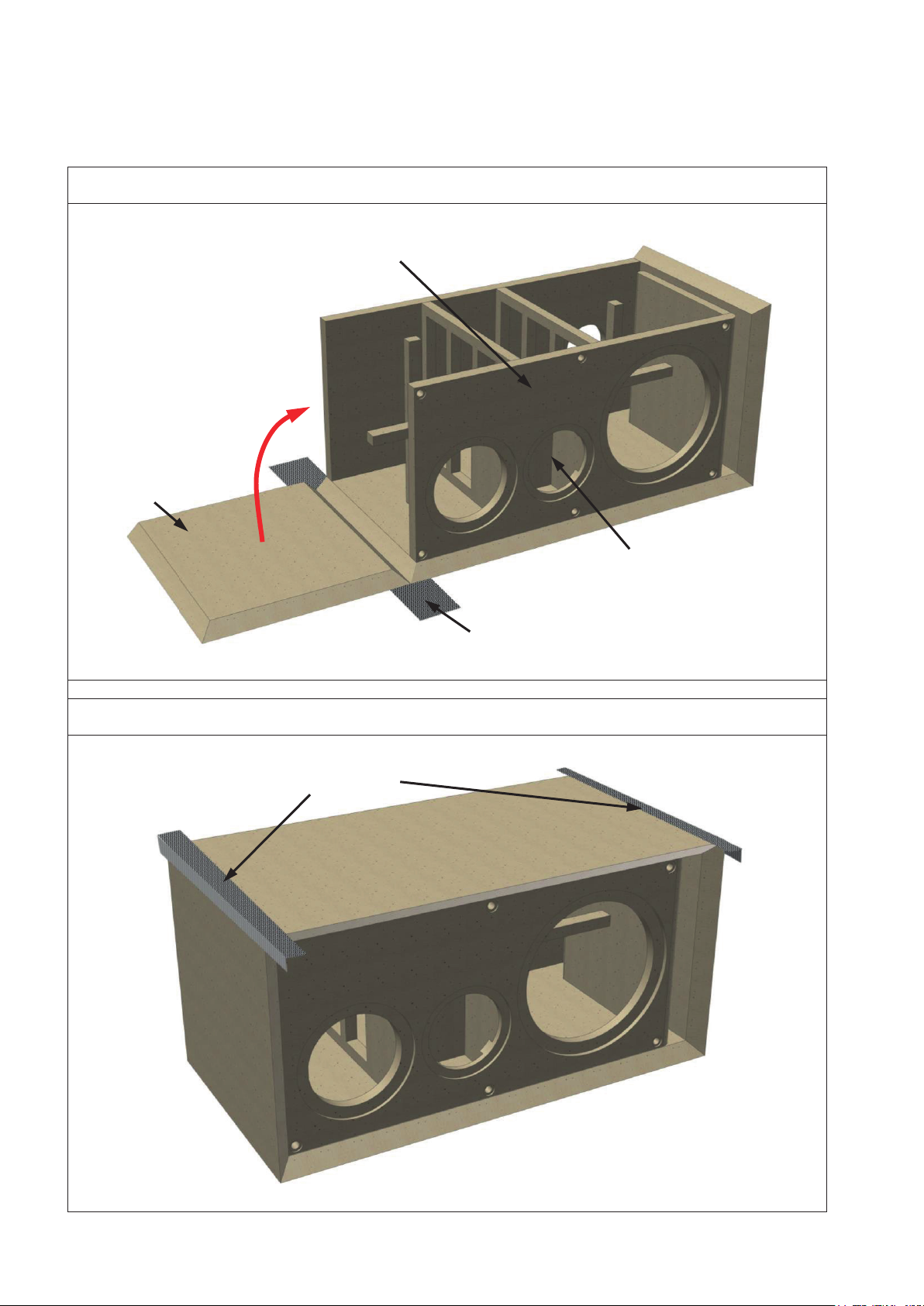
Nimrod
Schritt 5: Einsetzen der Frontplatte und verkleben des Deckels
Step 5: Installing the front and top panels
Schritt 6: Verkleben der Seitenplatte
Step 6: Gluing the side panel
Nach oben klappen
Klebeband
Frontplatte
Deckel
Auf Ausrichtung des Mitteltöners achten
Klebeband
Front panel
Fold up
Top panel
Adhesive tape
Pay attention to midrange orientation
Adhesive tape
10 HiFi Bauvorschläge 2020
Page 11
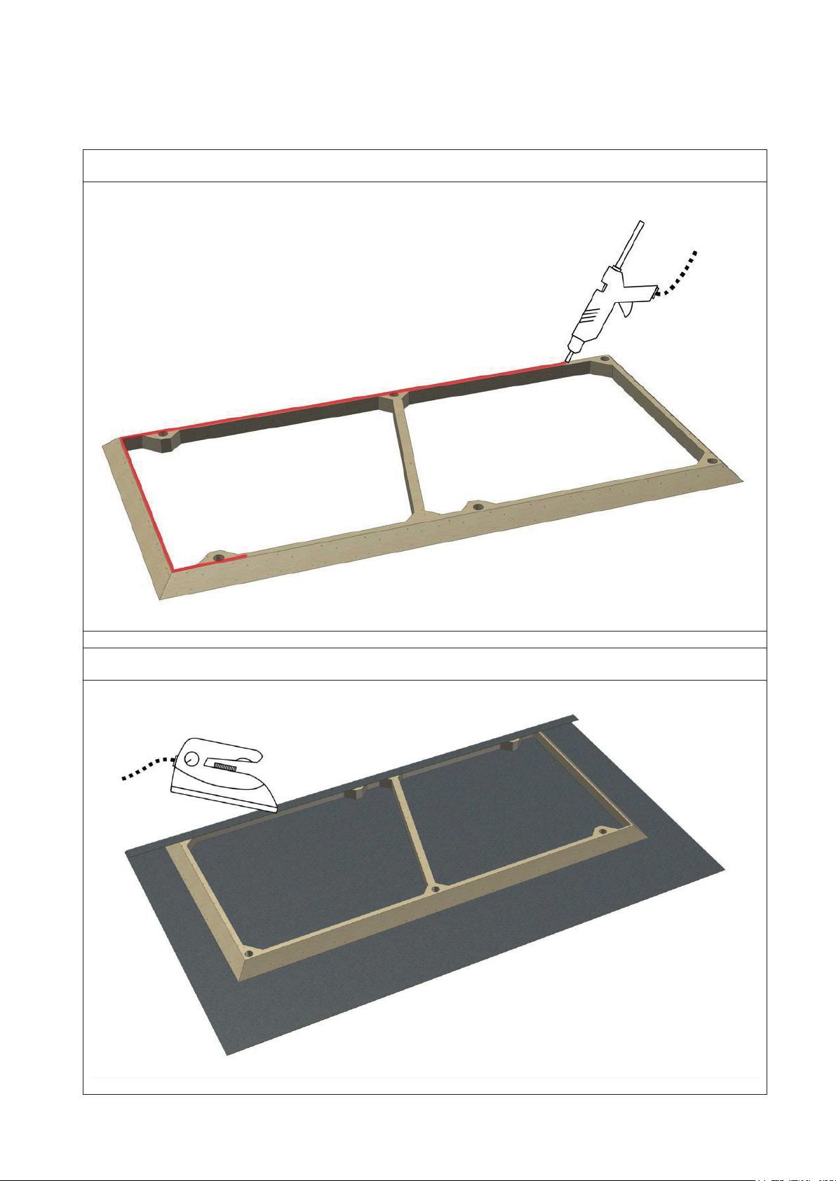
Nimrod
Schritt 7: Anbringen der Heißkleberspur auf die Rückseite des Rahmens
Step 7: Applying a bead of hot-melt glue to the back of the frame
Schritt 8: Auflegen des Bespannstoffs und befestigen mittels Bügeleisen
Step 8: Position the stretch material and fix it with an iron
HiFi Bauvorschläge 2020 11
Page 12
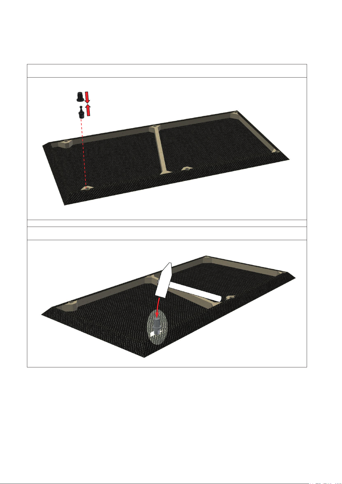
Nimrod
Schritt 9: Einsetzen der Rahmendübel, Teil 1
Step 9: Installing the frame dowels, part 1
Schritt 10: Einsetzen der Rahmendübel, Teil 2
Step 10: Installing the frame dowels, part 2
Connect the frame
dowel parts
12 HiFi Bauvorschläge 2020
Page 13
Nimrod
HiFi Bauvorschläge 2020 13
Page 14
Nimrod
Der Nageltrick / nail trick
14 HiFi Bauvorschläge 2020
Page 15
Nimrod
HiFi Bauvorschläge 2020 15
Page 16
Nimrod
16 HiFi Bauvorschläge 2020
Page 17
Nimrod
HiFi Bauvorschläge 2020 17
Page 18

Nimrod
18 HiFi Bauvorschläge 2020
 Loading...