

Page 1

VIPA System 300V
CPU | Manual
HB130E_CPU | Rev. 11/50
December 2011
Page 2

Copyright © VIPA GmbH. All Rights Reserved.
This document contai ns proprietary information of V IPA and is not to be discl osed or used except in accordance with applicable
agreements.
This material is protected by the copyright laws. It may not be reproduced, distri buted, or altered in any fashion by any entit y (either
internal or external to VIPA), except in accordance with applicable agreements, contracts or lic ensing, without the express written
consent of VIPA and t he business management owner of t he material.
For permission to reproduce or distribute, please contac t :
VIPA, Gesellschaft für Visualisi erung und P rozessautomatisierung mbH
Ohmstraße 4, D-91074 Herzogenaurach,Germany
Tel.: +49 (91 32) 744 -0
Fax.: +49 9132 744 1864
EMail: [email protected]
http://www.vipa.de
Note
Every effort has been made to ensure that the information contained in this document was complete and accurate at the time of
publishing. Nevertheless, the authors retain the right to modify the information. Thi s customer document describes all the hardware
units and functions k nown at t he present time. Descri pt i ons may be included for units which are not present at the customer site. The
exact scope of delivery is desc ri bed i n the respective purchase contract.
CE Conformity
Hereby, VIPA GmbH decl ares that the products and systems are in compliance with the essential requirem ent s and other relevant
provisions of the following directives:
• 2004/108/EC Electromagnetic Compatibility Directive
• 2006/95/EC Low Voltage Directive
Conformity is indic ated by the CE marking affixed to t he product.
Conformity Information
For more information regarding CE marking and Declaration of Conformity (DoC), please contact your local VIPA c ustomer service
organization.
Trademarks
VIPA, SLIO, S ys tem 100V, System 200V, System 300V, System 300S, System 400V, System 500S and Commander Compact are
registered trademarks of VIPA Gesellschaft für Visualisierung und Prozessautomatisierung mbH.
SPEED7 is a registered t rademark of profichip Gm bH.
SIMATIC, STEP, S INEC, S7-300 and S7-400 are registered trademarks of Siemens AG.
Microsoft und W i ndows are registered trademarks of Microsoft Inc., USA.
Portable Document Format (PDF) and Postscript are regi stered trademarks of Adobe Systems, Inc.
All other trademarks , logos and service or product m arks specified herein are owned by their respec tive companies.
Information product support
Contact your local VIP A Customer Service Organization representative if you wish to report errors or questions regarding the contents
of this document. If you are unable to locate a cus t omer service center, c ont act VIPA as follows:
VIPA GmbH, Ohm straße 4, 91074 Herzogenaurach, Germany
Telefax:+49 9132 744 1204
EMail: documentation@vi pa.de
Technical support
Contact your local VIP A Customer Service Organization representative if you encounter problem s with the product or have questions
regarding the product. If you are unable to l ocate a customer servi ce center, contact VIPA as follows:
VIPA GmbH, Ohm straße 4, 91074 Herzogenaurach, Germany
Telephone: +49 9132 744 1150 (Hotline)
EMail: [email protected]
Page 3

Manual VIPA System 300V Contents
Contents
About this manual....................................................................................1
Safety information.................................................................................... 2
Chapter 1
Safety Information for Users.................................................................1-2
General description of the System 300V..............................................1-3
Components.........................................................................................1-4
Chapter 2 Assembly and installation guidelines............................2-1
Overview..............................................................................................2-2
Installation dimensions.........................................................................2-3
Installation at the profile rail..................................................................2-4
Cabling.................................................................................................2-6
Installation Guidelines........................................................................2-10
Chapter 3 Hardware description .....................................................3-1
Introduction..........................................................................................3-2
Operating structure of a CPU...............................................................3-3
Function security of the VIPA CPUs.....................................................3-5
Application fields..................................................................................3-6
System overview..................................................................................3-8
Structure ............................................................................................3-13
Components.......................................................................................3-17
Technical Data...................................................................................3-23
Chapter 4 Deployment CPU 31x...................................................... 4-1
Fast introduction...................................................................................4-2
Hints for the deployment of the MPI interface.......................................4-4
Installation............................................................................................4-5
Start-up behavior..................................................................................4-6
Addressing...........................................................................................4-7
Project engineering..............................................................................4-9
Parameter adjustment CPU ...............................................................4-12
Project transfer...................................................................................4-13
Operating modes................................................................................4-19
Overall Reset .....................................................................................4-20
Firmware update................................................................................4-22
VIPA specific diagnostic entries.........................................................4-25
Using test functions for the control and monitoring of variables..........4-27
Chapter 5 Deployment CPU 31x with Profibus...............................5-1
Overview..............................................................................................5-2
Project engineering CPU with integrated Profibus master....................5-3
Deployment as Profibus DP slave........................................................5-5
Profibus installation guidelines.............................................................5-7
Commissioning and Start-up behavior................................................5-10
Basics..............................................................................1-1
HB130E - CPU - Rev. 11/50 i
Page 4

Contents Manual VIPA System 300V
Chapter 6 Deployment CPU 31x with TCP/IP..................................6-1
Principles..............................................................................................6-2
Protocols..............................................................................................6-4
Network planning .................................................................................6-8
IP address..........................................................................................6-10
Project Engineering of the CPU 31xNET............................................6-11
PG/OP communication.......................................................................6-24
Firmware update and reboot .............................................................. 6-27
Access control....................................................................................6-30
Activate clock master .........................................................................6-31
IP parameters.....................................................................................6-33
Activate IPC .......................................................................................6-34
Start-up behavior................................................................................6-35
System properties of the CPU 31xNET..............................................6-36
Communication to other systems.......................................................6-37
Test program for TCP/IP connections................................................6-40
Sample communication TCPTest - CPU 31xNET...............................6-47
Sample communication CPU 31xNET - CPU 31xNET........................6-57
Support for error search.....................................................................6-67
Appendix................................................................................................A-1
Index....................................................................................................A-1
ii HB130E - CPU - Rev. 11/50
Page 5

Manual VIPA System 300V About this manual
About this Manual
This manual describes t he operation of the CPU 31x in the System 300V
from VIPA. The text provides details on the hardware, the programming
and the functions integrated into the unit as well as Profibus and TCP/IP
applications.
Overview
Chapter 1: Basics
This introduction includes recommendations on the handling of the
modules of the VIPA System 300V and introduces you to central res.
decentral automation systems.
Chapter 2: Assembly and installation guidelines
All information that you need for installation and cabling of a PLC with
components of the System 300V.
Chapter 3: Hardware description
The CPUs 314 to 317 are available in different variants. This chapter
describes the specifications of these variants.
Chapter 4: Deployment CPU 31x
General information for operating the CPU31x like address allocation,
operating modes, usage of t he MMC and the MP-Interface.
Chapter 5: Deployment CPU 31x with Profibus
This chapter contains an description of the inst allation and configurat ion of
the System 300V CPUs via Profibus.
Chapter 6: Deployment CPU 31x with TCP/IP
This chapter describes the operating of the CPU31xNET and the
communication via TCP/IP.
HB130E - CPU - Rev. 11/50 1
Page 6
About this manual Manual VIPA System 300V
Objective and
contents
Target audience
Structure of the
manual
Guide to the
document
This manual describes t he CPUs 31x from VIPA which can be used at the
System 300V. It contains a descript ion of structure, project engineering and
technical data.
The manual is targeted at users who have a background in automation
technology.
The manual consists of chapters. Every chapter provides a self-contained
description of a specific topic.
The following guides are available in the manual:
• an overall table of contents at the beg inning of the manual
• an overview of the topics for every chapter
• an index at the end of the manual.
Availability
Icons
Headings
The manual is available in:
• printed form, on paper
• in electronic form as PDF-file (Adobe Acrobat Reader)
Important passages in the text are highlighted by following icons and
headings:
Danger!
Immediate or likely danger.
Personal injury is possible.
Attention!
Damages to property is likely if these warnings are not heeded.
Note!
Supplementary information and usef ul tips.
2 HB130E - CPU - Rev. 11/50
Page 7
Manual VIPA System 300V Safety information
Safety information
Applications
conforming with
specifications
Documentation
The CPUs 31x are constructed and manufactur ed for:
• System 300 components from VIPA and Siemens
• communication and process control
• general control and automation applications
• industrial applications
• operation within the environmental conditions specified in the technical
data
• installation into a cubicle
Danger!
This device is not certified for applications in
• in explosive environments (EX-zone)
The manual must be available to all personnel in the
• project design department
• installation department
• commissioning
• operation
Disposal
The following conditions must be met bef ore usi ng or commi ssioning
the components described in this manual:
• Modification to the process control system should only be carried out
when the system has been disconnected from power!
• Installation and modifications only by properly trained personnel
• The national rules and regulations of the respective country must be
satisfied (installation, safety, EMC ...)
National rules and regulations apply to the disposal of t he unit!
HB130E - CPU - Rev. 11/50 3
Page 8

Safety information Manual VIPA System 300V
4 HB130E - CPU - Rev. 11/50
Page 9

Manual VIPA System 300V Chapter 1 Basics
Chapter 1 Basics
Outline
Content
Main theme of this chapter is to give you an overview about the System
300V from VIPA. We will outline the possibilities of the installation of
central res. decentral systems.
This chapter also contains general inf ormation about the System 300V like
measurements, hints for inst allat ion and t he environm ent al conditions.
Topic Page
Chapter 1
Safety Information for Users.................................................................1-2
General description of the System 300V..............................................1-3
Components.........................................................................................1-4
Basics..............................................................................1-1
HB130E - CPU - Rev. 11/50 1-1
Page 10

Chapter 1 Basics Manual VIPA System 300V
Safety Information for Users
Handling of
electrostatically
sensitive modules
VIPA modules make use of highly integrated components in MOSTechnology. These components are extremely sensitive to over-voltages
that can occur during electrostatic discharges.
The following symbol is attached to modules that can be destroyed by
electrostatic discharges.
The symbol is located on the module, the module rack or on packing
material and it indicates the presence of electrostatically sensitive
equipment.
It is possible that electrostatically sensitive equipment is destroyed by
energies and voltages that are far less than the human threshold of
perception. These voltages can occur where persons do not discharge
themselves before handling electrostatically sensitive modules and they
can damage components thereby, causing the module to become
inoperable or unusable. Modules, damaged in this way, are normally not
immediately recognized. The according er ror may occur only after a while
of operation.
Modules that have been damaged by electrostatic discharges can f ail after
a temperature change, mechanical shock or changes in the electrical load.
Only the consequent implementation of protection devices and meticulous
attention to the applicable rules and regulat ions for handling the respective
equipment can prevent failures of electrostatically sensitive modules.
Shipping of modules
Modules must be shipped in the original packing mater ial.
Measurements and
alterations on
electrostatically
sensitive modules
When you are conducting measurements on electrostatically sensitive
modules you should take the following precautions:
• Floating instruments must be discharged before use.
• Instruments must be grounded.
Modifying electrostatically sensitive modules you should only use soldering
irons with grounded tips.
Attention!
Personnel and instruments should be grounded when working on
electrostatically sensitive modules.
1-2 HB130E - CPU - Rev. 11/50
Page 11
Manual VIPA System 300V Chapter 1 Basics
General description of the System 300V
The System 300V
decentral
The System 300V is a modular automation system for middle and high
performance needs, that you can use either distributed or non-distributed.
The single modules are directly clipped to a 530 mm backplane and are
connected together with the help of bus clips at t he backside.
The single modules of the VIPA System 300V are design compatible to
Siemens. Due to the compatible backplane bus it is no problem to mix the
modules from VIPA and Siemens.
The CPUs of the System 300V are instruction set compatible to S7-300
from Siemens. The CPUs are programmed via the VIPA programming
software WinPLC7 or the SIMATIC manager from Siemens or other
available programming tools.
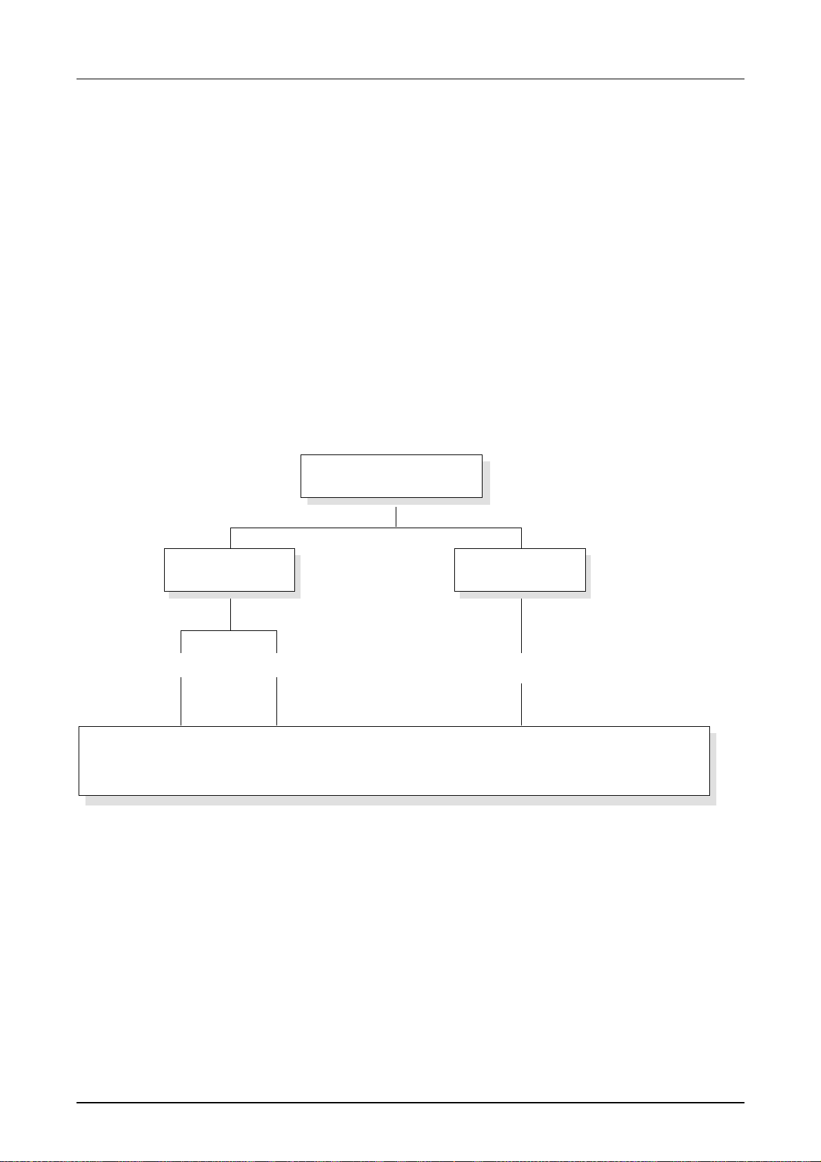
The following picture illustrates the performance range of the
System 300V:
System 300V
central
Profibus
PLC-CPUCAN
for STEP®7 from Siemens
Periphery
Dig. IN / Dig. OUT / Anal. IN / Anal. OUT / PS
HB130E - CPU - Rev. 11/50 1-3
Page 12

Chapter 1 Basics Manual VIPA System 300V
Components
Central system
Decentral system
Peripheral
modules
The System 200V series consists of a number of PLC-CPUs. These are
programmed in STEP
7 from Siemens. Herefore you may use WinPLC7
from VIPA or the SIMATI C m anager from Siemens.
CPUs with integrated Ethernet interfaces or additional serial interfaces
simplify the integration of the PLC into an existing network or the
connection of additional peripheral equipment .
The application program is saved in Flash or an additional plug -in memory
module.
Because of the automatic addressing, up to 32 peripheral modules can be
called by the System 300V CPUs.
In combination with a Profibus DP master and slave the PLC-CPUs or the
PC-CPU form the basis f or a Profibus-DP network in accordance with DIN
19245-3.
The DP network can be configured with the hardware configurator from
Siemens. Together with the hardware configuration you transfer your
project into the CPU via MPI. Another component of the decentral system
is the CAN-Slave. It allows the link-up to the fieldbus system CANopen.
A large number of peripheral modules are available f rom VIPA, for example
digital as well as analog inputs/outputs.
These peripheral modules can be deployed central as well as decentral.
Dimensions/
Weight
Installation
• Profile rail 530mm
• Peripheral modules with recessed labeling
• Dimensions of the basic enclosure:
1tier width: (W xHxD) in mm: 40x125x120
2tier width: (W xHxD) in mm: 80x125x120
3tier width: (W xHxD) in mm: 120x125x120
Please regard that the power supply and header modules like CPUs and
couplers may only plugged-in at the left side.
Power Supply I/O PeripheryCPU
PS307/5A
DC24V
VOLTAGE
230
SELECTOR
ON
OFF
L1
N
IN AC 120/230V
2.2/1.3A
50-60Hz
OUT DC 24V/5A
L+
X1
M
DC 24V
+
L+
-
M
+
L+
-
M
PS DVI CF PB-DP
CPU314NET
X5
PLC
VIPA 314-3SL01
X2 X3
MP I
DI 16xDC24V
PWR
RUN
STOP
SF
FRCE
MMC
MMC
DESL
RUN
STOP
MRES
X2
34
2
VIPA 321-1BH00
.0
.1
.2
.3
.4
.5
.6
.7
SM321
.0
.1
.2
.3
.4
.5
.6
.7
X2
34
1-4 HB130E - CPU - Rev. 11/50
Page 13

Manual VIPA System 300V Chapter 1 Basics
Reliability
Environmental
conditions
Green Cable
for project
engineering
• Wiring by means of spring pressure connections (CageClamps) at the
front connector
• Core cross-section 0.08...2.5mm
2
or 1.5 mm2
• Total isolation of the wiring at m odule change
• Potential separation of all modules to the backplane bus
• Burst/ESD acc. IEC 61000-4-2/I EC 61000- 4- 4 (up to level 3)
• Shock resistance acc. IEC 60068-2-6 / I EC 60068- 2- 27 ( 1G /12G)
• Operating temperature: 0 ... +60°C
• Storage temperature: -25 ... +70°C
• Relative humidity: 5...95% without condensation
• Ventilation by means of a fan is not required
For project engineering of your DP slave you may transfer your projects
from your PC to the CPU serial via MPI by using the "Green Cable". Please
also regard the hints to the Gr een Cable in this chapter!
Integrated
power supply
Compatibility
Every Profibus slave has an internal power supply. This power supply
requires DC 24V. In addition to the electronics on the bus coupler, the
supply voltage is also used to power any modules connected to the
backplane bus. Please note that the maximum curr ent that the integrated
power supply can deliver to the backplane bus is 3.5A.
The power supply is protected against reverse polarity and overcurrent.
The digital in-/ output modules of the System 300V f rom VIPA are pin and
function compatible to Siemens.
The project engineering happens in t he SIMATIC manager from Siemens.
Note!
For programming of a System 300V CPU from VIPA please use always the
CPU 315-2DP (6ES7 315-2AF03 V1.2) from Siemens in the hardware
catalog.
Please note the Profibus address 1 of t he CPU 31x is system dependent
reserved.
For the project engineering, a thorough knowledge of the Siemens
SIMATIC manager and the hardware configurator is required!
HB130E - CPU - Rev. 11/50 1-5
Page 14

Chapter 1 Basics Manual VIPA System 300V
1-6 HB130E - CPU - Rev. 11/50
Page 15

Manual VIPA System 300V Chapter 2 Assembly and installation guidelines
Chapter 2 Assembly and installation guidelines
Outline
Content
In this chapter you will find all information, r equired for the installation and
the cabling of a process control with the component s of the System 300V.
Topic Page
Chapter 2
Overview..............................................................................................2-2
Installation dimensions.........................................................................2-3
Installation at the profile rail..................................................................2-4
Cabling.................................................................................................2-6
Installation Guidelines........................................................................2-10
Assembly and installation guidelines............................2-1
HB130E - CPU - Rev. 11/50 2-1
Page 16
Chapter 2 Assembly and installation guidelines Manual VIPA System 300V
Overview
General
Profile rail
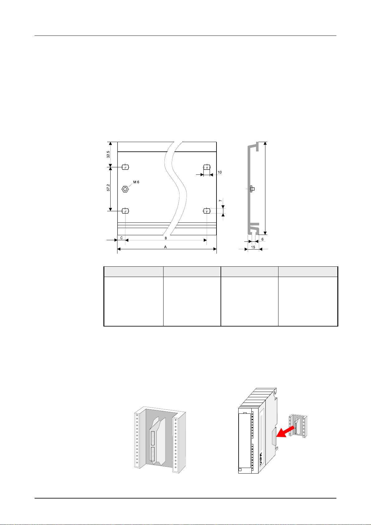
The single modules are directly installed on a prof ile rail and connected via
the backplane bus coupler. Bef ore installing the modules you have to clip
the backplane bus coupler to the module f r om the backside.
The backplane bus coupler are included in the delivery of the peripheral
modules.
122
G
Bus connector
Order number A B C
VIPA 390-1AB60 160mm 140mm 10mm
VIPA 390-1AE80 482mm 466mm 8.3mm
VIPA 390-1AF30 530mm 500mm 15mm
VIPA 390-1AJ30 830mm 800mm 15mm
VIPA 390-9BC00* 2000mm
* Unit pack: 10 pieces
no Drillings
15mm
For the communication between the modules the System 300V uses a
backplane bus connector. The back plane bus connector are included in the
delivering of the peripheral modules and are clipped at the module from
behind before installing it to the profile rail.
2-2 HB130E - CPU - Rev. 11/50
Page 17
Manual VIPA System 300V Chapter 2 Assembly and installation guidelines
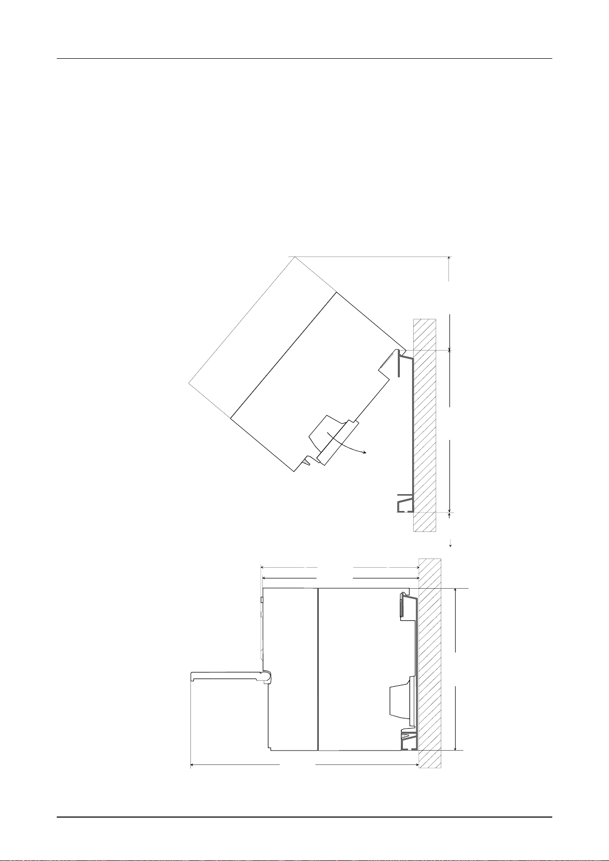
Installation dimensions
Overview
Dimensions Basic
enclosure
Dimensions
Here follows all the important dimensions of the System 300V.
1tier width (WxHxD) in mm: 40 x 125 x 120
2tier width (WxHxD) in mm: 80 x 125 x 120
3tier width (WxHxD) in mm: 120 x 125 x 120
65mm
122mm
40mm
Installation
dimensions
175mm
125mm
120mm
125 mm
HB130E - CPU - Rev. 11/50 2-3
Page 18
Chapter 2 Assembly and installation guidelines Manual VIPA System 300V
Installation at the profile rail
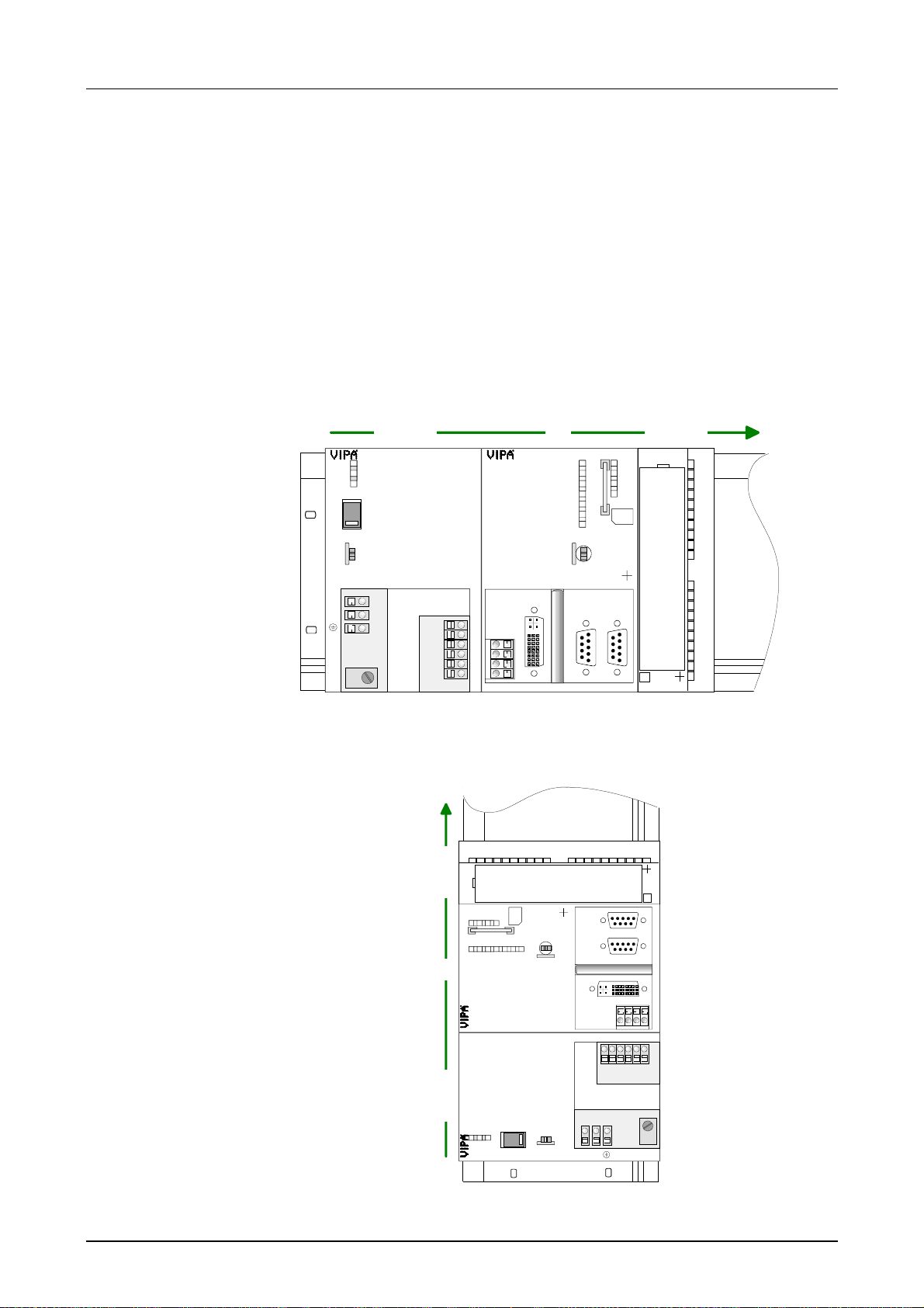
Structure:
You may install the System 300V as well horizontal as vertical. Please
regard the allowed environment temperatures:
• horizontal structure: from 0 t o 60°
• vertical structure: from 0 to 40°
The horizontal structur e always starts at the lef t side with the power supply
and the CPU, then you plug-in the peripheral modules beside to the right.
You may plug-in maximum 32 peripheral modules to the CPU.
Power Supply I/O PeripheryCPU
MMC
X2
3
4
VIPA 321-1BH00
DI 16xDC24V
.0
.1
.2
.3
.4
.5
.6
.7
SM321
.0
.1
.2
.3
.4
.5
.6
.7
X2
3
4
PS307/5A
DC24V
VOLTAGE
230
SELECTOR
ON
OFF
L1
N
IN AC 120/230V
2.2/1.3A
50-60Hz
OUT DC 24V/ 5A
L+
M
L+
M
L+
M
CPU314NET
X5
X1
DC 24V
+
+
-
PS DVI CF PB-DP
PLC
PWR
RUN
STOP
SF
FRCE
MMC
DESL
RUN
STOP
MRES
VIPA 314-3SL01
X2 X3
2
MP I
The vertical structure is turned for 90° against the clockwise direction.
MMC
.7
.0.1.2.3.4.5.6
SM321
34
X2
RUN
STOP
MRES
DESL
VIPA 314-3SL01
X5
SELECTOR
ON
OFF
L1
X2 X3
DC 24V
X1
L+ML+ML+
N
+-+
.7
234
X
VIPA 321-1BH 00
2
MP I
-
PS DVI CF PB-DP
M
Power Supply I/O PeripheryCPU
.0.1.2.3.4.5.6
DI 16xDC24V
PWR
RUN
STOPSFFRCE
PLC
CPU314NET
2.2/1.3A
PS307/5A
IN AC 120/230V
DC24V
MMC
50-60Hz
OUT DC 24V/5A
VOLTAGE
230
2-4 HB130E - CPU - Rev. 11/50
Page 19
Manual VIPA System 300V Chapter 2 Assembly and installation guidelines
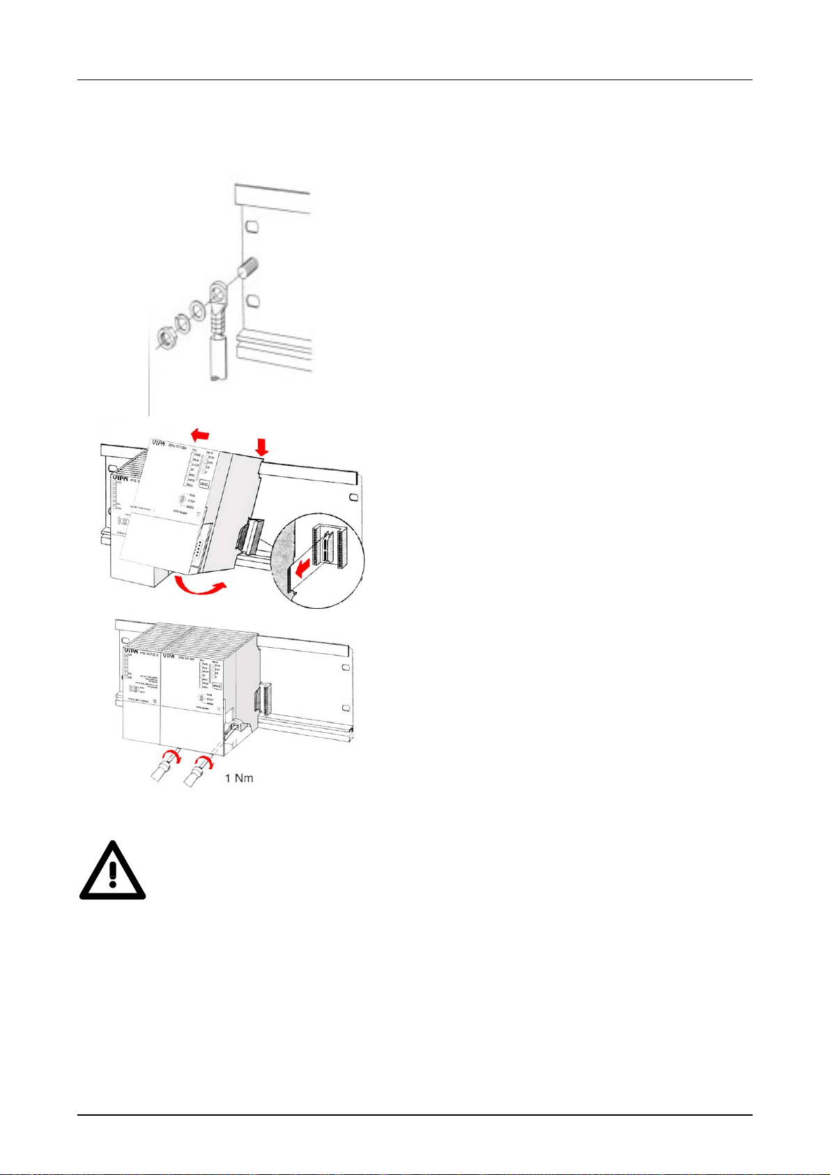
Approach
• Bolt the profile rail with the background (screw
size: M6), so that you still have minimum 65mm
space above and 40mm below the profile rail.
• If the back ground is a grounded metal or device
plate, please look for a low-impedance connection between profile rail and background.
• Connect the profile rail with the protected earth
conductor. For this purpose there is a bolt with
M6-thread.
• The minimum cross-section of the cable to the
protected earth conductor has to be 10mm
2
.
• Stick the power supply to the profile r ail and pull it
to the left side to t he grounding bolt of the pr ofile
rail.
• Fix the power supply by screwing.
• Take a bus coupler and click it at t he CPU from
behind like shown in the picture.
• Stick the CPU to the profile rail right from the
power supply and pull it to the power supply.
• Click the CPU downwards and bolt it like shown.
• Repeat this procedure with the peripheral
modules, by clicking a backplane bus coupler,
stick the module right from the modules you've
already fixed, click it downwards and connect it
with the backplane bus coupler of the last module
and bolt it.
Danger!
• Before installing or overhauling the System 300V, the power supplies
must be disconnected from voltage ( pull the plug or remove the fuse)!
• Installation and modifications only by properly trained personnel!
HB130E - CPU - Rev. 11/50 2-5
Page 20
Chapter 2 Assembly and installation guidelines Manual VIPA System 300V
Cabling
Overview
CageClamp
technology (gray)
1
The power supplies and CPUs are exclusively delivered with CageClamp
contacts. For the signal modules the front connectors are available from
VIPA with screw contacts. In the following all connecting types of the power
supplies, CPUs and input/output modules are described.
Danger!
• Before installation or overhauling, the power supplies must be
disconnected from voltage (pull the plug or remove the fuse)!
• Installation and modifications only by properly trained personnel!
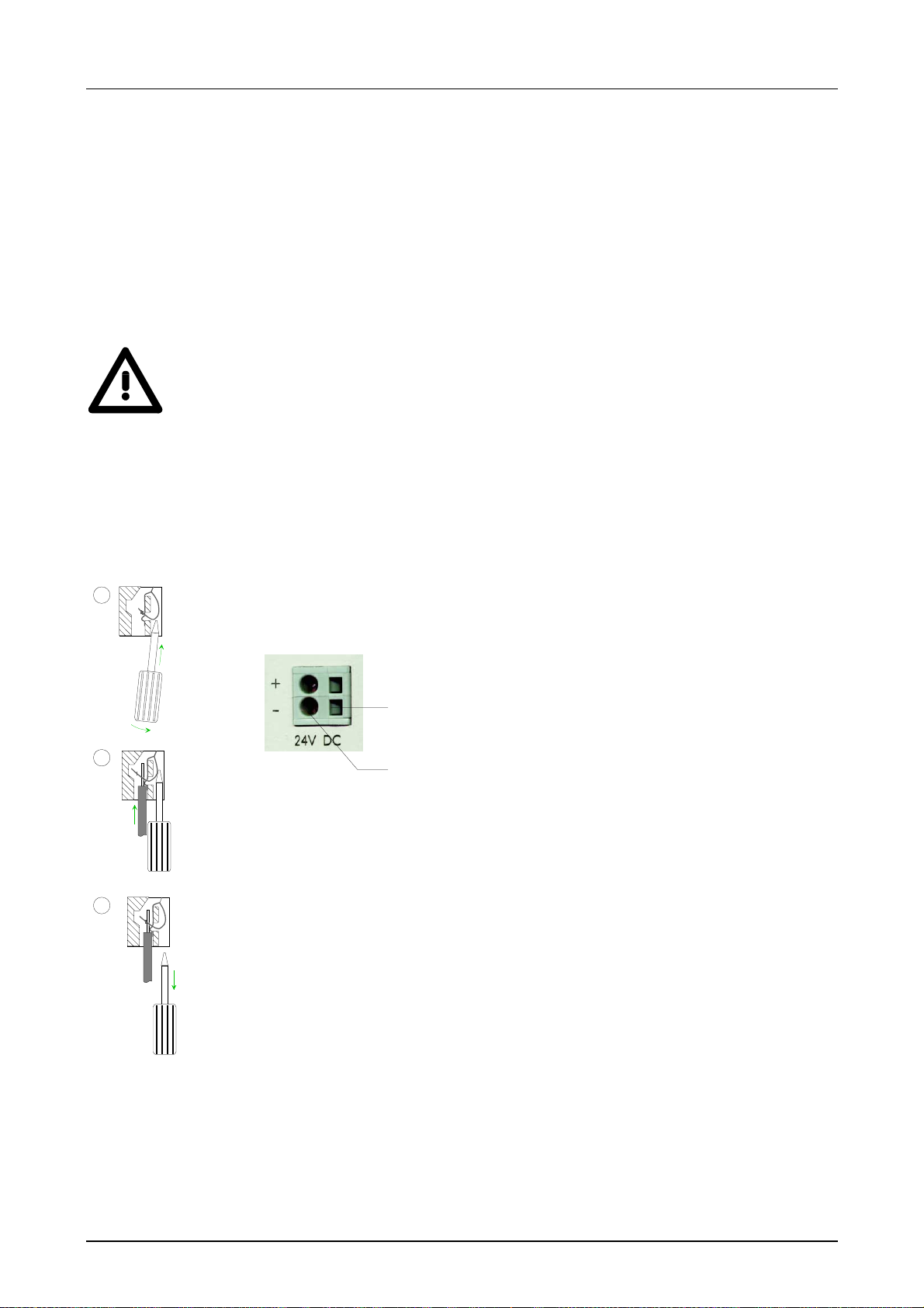
For the cabling of power supplies, bus coupler s and parts of the CPU, g ray
connectors with CageClamp technology are used.
2
You may connect wires with a cross-section of 0.08mm
to 2.5mm2. You
can use flexible wires without end case as well as stiff wires.
[1] Rectang ular opening for screwdriver
[2] Round opening for wires
1
2
2
The picture on the left side shows the cabling st ep by step from top view.
• To conduct a wire you plug a fitting screwdriver obliquely into the
rectangular opening like shown in the pictur e.
3
• To open the contact spring you have to push the screwdriver in the
opposite direction and hold it.
• Insert the insulation str iped wire into the round opening. You may use
wires with a cross-section from 0.08mm
2
to 2.5mm2.
• By removing the screwdriver the wire is connected safely with the plug
connector via a spring.
2-6 HB130E - CPU - Rev. 11/50
Page 21
Manual VIPA System 300V Chapter 2 Assembly and installation guidelines
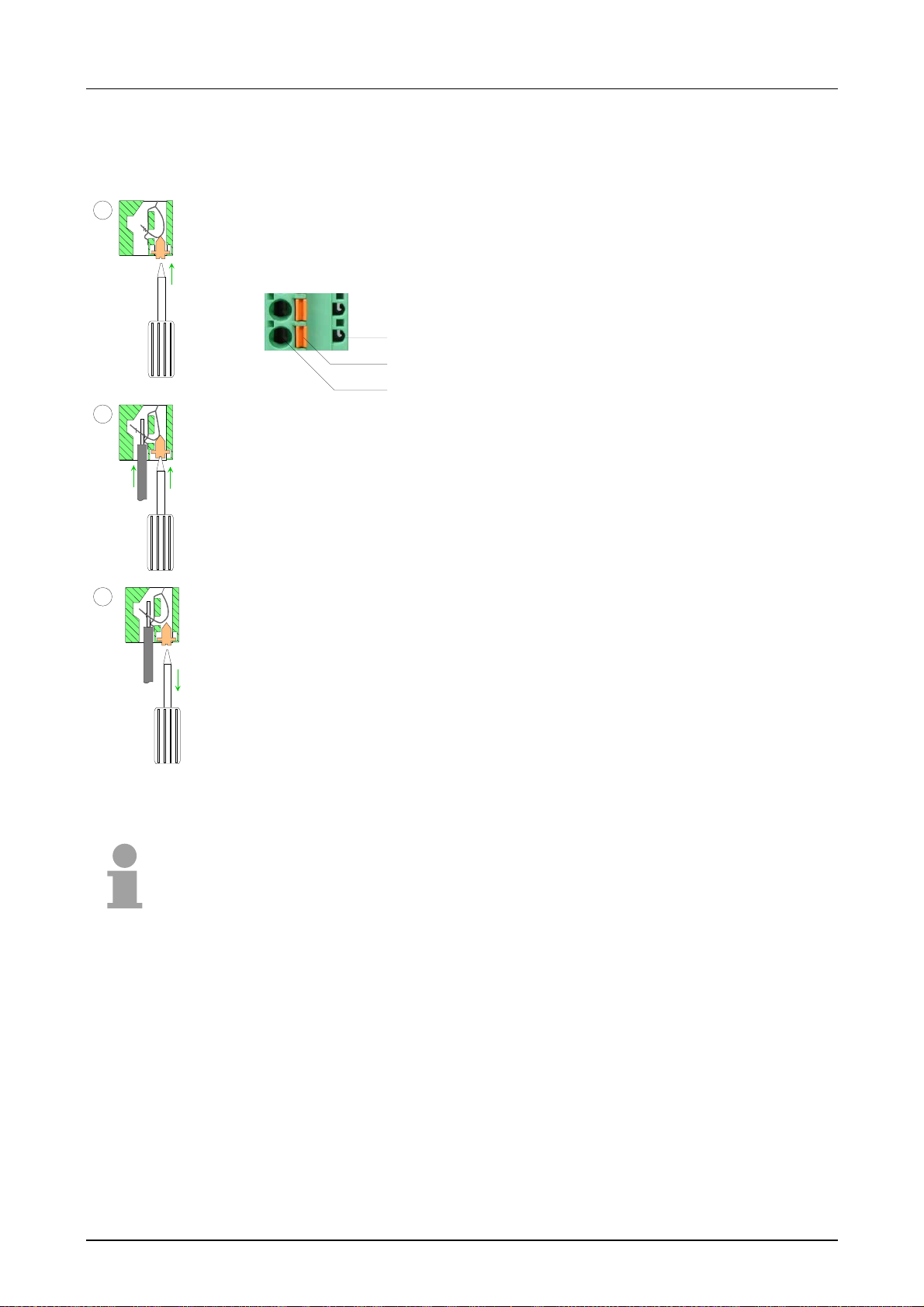
CageClamp
technology (green)
1
2
3
For the cabling of e.g. the power supply of a CPU, green plugs with
CageClamp technology are deployed.
Here also you may connect wires with a cross-section of 0.08mm2 to
2.5mm
2
. You can use flexible wires without end case as well as stiff wires.
[1] Test point for 2mm test tip
1
[2] Locking ( or ange) for screwdriver
[3] Round opening for wires
2
3
The picture on the left side shows the cabling st ep by step from top view.
• For cabling you push the locking vertical to the inside with a suiting
screwdriver and hold the screwdriver in this position.
• Insert the insulation str iped wire into the round opening. You may use
wires with a cross-section from 0.08mm
• By removing the screwdriver the wire is connected safely with the plug
connector via a spring.
2
to 2.5mm2.
Note!
In opposite to the gray connection clamp f rom above, the green connection
clamp is realized as plug that can be clipped off carefully even if it is still
cabled.
HB130E - CPU - Rev. 11/50 2-7
Page 22
Chapter 2 Assembly and installation guidelines Manual VIPA System 300V
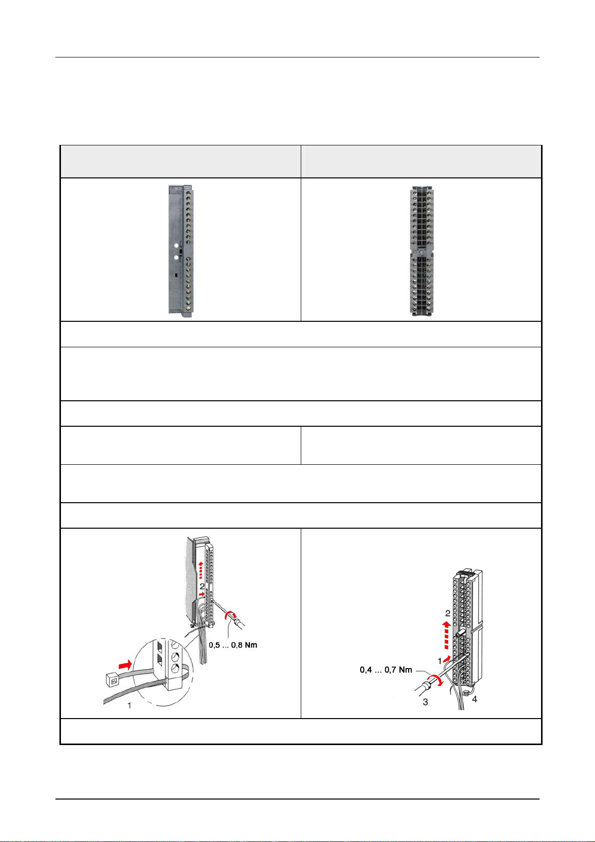
Front connectors
of the in-/output
modules
20pole screw connection
Open the front flap of your I/O module.
Bring the front connect or in cabling position.
Herefore you plug the fr ont connector on the module until it locks. In this position the front
connector juts out of the m odule and has no cont act yet.
In the following the cabling of the three variants of the front-facing
connector is shown:
For the I/O modules the following plugs are available at VIPA:
40pole screw connection
VIPA 392-1AJ00
VIPA 392-1AM00
Deisolate your wires. If needed, use core end cases.
Thread the included cable binder into the f r ont
connector.
If you want to lead out your cables from the bot t om of the module, start with the cabling from
bottom to top, res. from top to bottom, if the cables should be led out at the top.
Bolt also the connection screws of not cabled screw clamps.
Put the included cable binder around the cable
bundle and the front connector.
Fix the cable binder for the cable bundle.
2-8 HB130E - CPU - Rev. 11/50
continued ...
Page 23
Manual VIPA System 300V Chapter 2 Assembly and installation guidelines
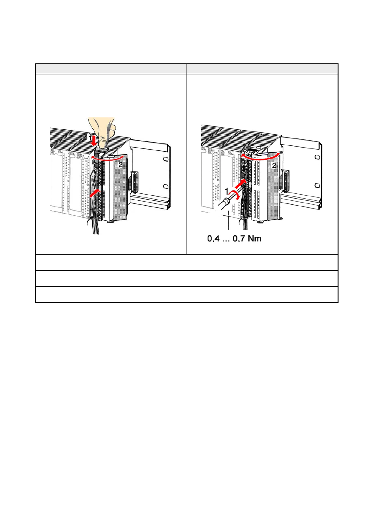
... continue
20pole screw connection 40pole screw connection
Push the release key at the front connect or on
the upper side of the module and at the sam e
time push the front connector int o the module
until it locks.
Now the front connector is electrically connected with your module.
Bolt the fixing screw of the front connector.
Close the front flap.
Fill out the labeling strip to mark the single channels and push the strip into the front flap.
HB130E - CPU - Rev. 11/50 2-9
Page 24

Chapter 2 Assembly and installation guidelines Manual VIPA System 300V
Installation Guidelines
General
What means
EMC?
Possible
interference
causes
The installation guidelines contain information about the interference free
deployment of System 300V systems. There is the descr iption of the ways,
interference may occur in your control, how you can make sure the
electromagnetic digestibilit y (EMC), and how you manage the isolat ion.
Electromagnetic digestibility (EMC) means the ability of an electrical
device, to function error free in an electromagnetic environment without
being interferenced res. without int er ferencing the environment.
All System 300V components are developed for the deployment in hard
industrial environments and fulf ill high demands on the EMC. Nevertheless
you should project an EMC planning before installing the components and
take conceivable interference causes into account.
Electromagnetic interferences may interfere your control via different ways:
• Fields
• I/O signal conductors
• Bus system
• Current supply
• Protected earth conductor
Depending on the spreading medium (lead bound or lead free) and the
distance to the interference cause, interferences to your control occur by
means of differ ent coupling mechanisms.
One differs:
• galvanic coupling
• capacitve coupling
• inductive coupling
• radiant coupling
2-10 HB130E - CPU - Rev. 11/50
Page 25

Manual VIPA System 300V Chapter 2 Assembly and installation guidelines
Basic rules for
EMC
In the most times it is enough to take care of some elementary rules to
guarantee the EMC. Please regard the f ollowing basic rules when installing
your PLC.
• Take care of a correct area-wide grounding of the inactive metal parts
when installing your components.
- Install a central connection between the ground and the protected
earth conductor system.
- Connect all inactive metal extensive and impedance-low.
- Please try not to use aluminum parts. Aluminum is easily oxidizing
and is therefore less suitable f or grounding.
• When cabling, take care of the correct line routing.
- Organize your cabling in line groups (high voltage, current supply,
signal and data lines).
- Always lay your high voltage lines and signal res. data lines in
separate channels or bundles.
- Route the signal and data lines as near as possible beside ground
areas (e.g. suspension bars, met al r ails, tin cabinet).
• Proof the correct fixing of the lead isolation.
- Data lines must be laid isolated.
- Analog lines must be laid isolated. When transmitting signals with
small amplitudes the one sided laying of the isolation may be
favorable.
- Lay the line isolation extensively on a isolation/protected earth con-
ductor rail directly after the cabinet entry and fix the isolation with
cable clamps.
- Make sure that the isolation/protected earth conductor rail is
connected impedance-low with the cabinet.
- Use metallic or metallized plug cases for isolated data lines.
• In special use cases you should appoint special EMC actions.
- Wire all inductivities with erase links, that ar e not addressed by the
System 300V modules.
- For lightening cabinets you should prefer incandescent lamps and
avoid luminescent lamps.
• Create an homogeneous reference potential and ground all electrical
operating supplies when possible.
- Please take care for the targeted employment of the grounding
actions. The grounding of the PLC is a protection and functionality
activity.
- Connect installation parts and cabinets with the System 300V in star
topology with the isolation/protected earth conductor system. So you
avoid ground loops.
- If potent ial differences between installation parts and cabinets occur,
lay sufficiently dimensioned potential compensation lines.
HB130E - CPU - Rev. 11/50 2-11
Page 26

Chapter 2 Assembly and installation guidelines Manual VIPA System 300V
Isolation of
conductors
Electrical, magnetical and electromagnetical interference fields are
weakened by means of an isolation, one talks of absorption.
Via the isolation rail, that is connected conductive with the rack,
interference currents are shunt via cable isolation to the ground. Hereby
you have to make sure, that the connection to the protected earth conductor is impedance-low, because otherwise the interference currents may
appear as interference cause.
When isolating cables you have to regard the following:
• If possible, use only cables with isolation tangle.
• The hiding power of the isolation should be higher than 80%.
• Normally you should always lay the isolation of cables on both sides.
Only by means of the both-sided connect ion of the isolat ion you achieve
a high quality interference suppr ession in the higher frequency area.
Only as exception you may also lay the isolation one-sided. Then you
only achieve the absorption of the lower frequencies. A one-sided
isolation connection may be convenient, if:
- the conduction of a potential compensating line is not possible
- analog signals (some mV res. µA) are transferr ed
- foil isolations (static isolations) are used.
• With data lines always use metallic or metallized plugs for serial
couplings. Fix the isolation of the data line at the plug rack. Do not lay
the isolation on the PIN 1 of the plug bar!
• At stationary operation it is convenient to deisolate the isolated cable
interruption free and lay it on the isolat ion/ protected earth conductor line.
• To fix the isolation tangles use cable clamps out of metal. The clamps
must clasp the isolation extensively and have well contact.
• Lay the isolation on an isolation rail directly after t he entr y of t he cable in
the cabinet. Lead the isolation further on to the System 300V module
and don't lay it on there again!
Please regard at installation!
At potential differences between the grounding points, there may be a
compensation current via the isolation connected at both sides.
Remedy: Potential compensation line
2-12 HB130E - CPU - Rev. 11/50
Page 27

Manual VIPA System 300V Chapter 3 Hardware description
Chapter 3 Hardware description
Outline
Content
The CPUs 31x are available in different versions that ar e described in this
chapter. In addition to the hardware description the chapter also contains
installation and commissioning instructions and applications for the
memory modules of the System 300V f a m ily.
The technical data conclude the chapter.
Topic Page
Chapter 3
Introduction..........................................................................................3-2
Operating structure of a CPU...............................................................3-3
Function security of the VIPA CPUs.....................................................3-5
Application fields..................................................................................3-6
System overview..................................................................................3-8
Structure ............................................................................................3-13
Components.......................................................................................3-17
Technical Data...................................................................................3-23
Hardware description ..................................................... 3-1
HB130E - CPU - Rev. 11/50 3-1
Page 28

Chapter 3 Hardware description Manual VIPA System 300V
Introduction
General
Types
A CPU is an intelligent module. Here your driver software is processed.
Depending on your performance needs, you are able to choose between 4
different CPUs. The more power the chosen CPU has, the more user
memory it has. This is composed of load memory for the project
engineering and work memory for the program compiled from the project
engineering.
These CPUs are conceived for middle and large applications with
integrated 24V-Power supply. Additionally every CPU has a MMC slot at
the frontside. Every CPU has a MPI slot and is instruction compatible to
®
STEP
7 from Siemens.
The performance of the CPU series 314...317 corresponds to the S7-300
CPU-series from Siemens (except CPU 318) .
This CPUs series allows you the access to the peripheral modules of t he
System 300V. Via standardized com mands and prog ram s you may request
sensors and control actors. The CPU is parameterized by means of the
integrated MP
2
I-Interface.
The CPU 31x family is available in 4 different CPU versions with each 4
variants:
• CPU 31x SPS-CPU with DP slave
• CPU 31xDPM SPS-CPU with DP slave/master
• CPU 31xNET SPS-CPU with DP slave, Ethernet TCP/IP-Int erface,
4port Switch
• CPU 31xNET SPS-CPU with DP slave/master, Ethernet T CP/ I P-
Interface, 4port Switch
Versions
The following CPU versions are available:
CPU Work memory
in kBytes
Load memory
in kBytes
CPU 314 96 144
CPU 315 192 256
CPU 316 256 512
CPU 317 512 1024
Note!
The further description in this manual refers to the complete CPU family
CPU 31x. The CPUs 314...317 are funct ionally identical and they only differ
in their range of mem or y.
3-2 HB130E - CPU - Rev. 11/50
Page 29

Manual VIPA System 300V Chapter 3 Hardware description
Operating structure of a CPU
General
Cyclic processing
Timer processing
Alarm controlled
processing
Priority based
processing
A CPU supports the following modes of oper ation:
• cyclic operation
• timer processing
• alarm controlled operation
• priority based processing
Cyclic processing represents the major portion of all the processes that
are executed in the CPU. Identical sequences of operations are repeated in
a never ending cycle.
Where a process requires control signals at constant intervals you can
initiate certain operations based upon a timer, e.g. not critical monitoring
functions at one-second intervals.
If a process signal requir es a quick response you would allocate this signal
to an alarm controlled procedure. An alarm can activate a procedure in
your program.
The above processes are handled by the CPU in accordance with their
priority. Since a timer or an alarm event requires a quick reaction, the
CPU will interrupt the cyclic processing when these high-priority events
occur to react to the event. Cyclic processing will resume, once the
reaction has been processed. This means that cyclic processing has the
lowest priority.
CPU 31x
Applications
System routine
User application
HB130E - CPU - Rev. 11/50 3-3
The program that is pr esent in every CPU is divided as follows:
• System routine
• User application
The system routine organizes all those functions and procedures of the
CPU that are not related to a specific control application.
This consists of all the f unctions that are required for the processing of a
specific control application. The operating modules provide the interf aces
to the system routines.
Page 30

Chapter 3 Hardware description Manual VIPA System 300V
Operands of the
CPU 31x
Process image
and periphery
Bit memory
Timers and
counters
Data blocks
The following series of operands is available for programming the
CPU 31x:
• Process image and periphery
• Bit memory
• Timers and counters
• Data blocks
The user application can quickly access the process image of the inputs
and outputs PAA/PAE. You may manipulate the f o llowing types of data:
- individual Bits
- Bytes
- Words
- Double words
You may also gain direct access to peripheral modules via the bus from
user application. The following types of dat a ar e available:
- Bytes
- Words
- Blocks
The bit memory is an area of memory that is accessible by means of
certain operations. Bit memory is intended t o store f requent ly used working
data.
You may access the following types of data:
- individual Bits
- Bytes
- Words
- Double words
In your program you may load cells of the timer with a value between 10ms
and 9990s. As soon as the user application executes a start-operation, the
value of this timer is decremented by the interval that you have specified
until it reaches zero.
You may load counter cells with an initial value (max. 999) and increm ent
or decrement these when required.
A data block contains constants or variables in the form of bytes, words or
double words. You may always access the current data block by means of
operands.
You may access the following types of data:
- individual Bits
- Bytes
- Words
- Double words
3-4 HB130E - CPU - Rev. 11/50
Page 31

Manual VIPA System 300V Chapter 3 Hardware description
Function security of the VIPA CPUs
Security
mechanisms
Event concerns Effect
RUN → STOP
central digital outputs The outputs are set to 0V.
central analog outputs The voltage supply for the output channels is
decentral outputs The outputs are set to 0V.
decentral inputs The inputs are read constantly from the slave and
STOP → RUN
res. Power on
central analog outputs The behavior of the outputs at restart can be
decentral inputs The inputs are read constantly from the slave and
RUN general The program execution happens cyclically and can
PII: = Process image inputs
PIQ: = Process image outputs
The CPUs include security mechanisms like a Watchdog (100ms) and a
parameterizable cycle time surveillance (parameterizable min. 1ms) that
stop res. execute a RESET at the CPU in case of an error and set it into a
defined STOP state.
The VIPA CPUs are developed function secure and have the following
system properties:
general
general First the PII is deleted, the call of the OB 100
BASP (Befehls-Ausgabe-Sperre, i.e. command
output lock) is set.
switched off.
the recent values are put at disposal.
follows. After the execution of t he OB, the BASP is
set back and the cycle starts with:
Delete PIO → Read PII → OB 1.
preset.
the recent values are put at disposal.
therefore be foreseen:
Read PII → OB 1 → Write PIQ.
HB130E - CPU - Rev. 11/50 3-5
Page 32
Chapter 3 Hardware description Manual VIPA System 300V
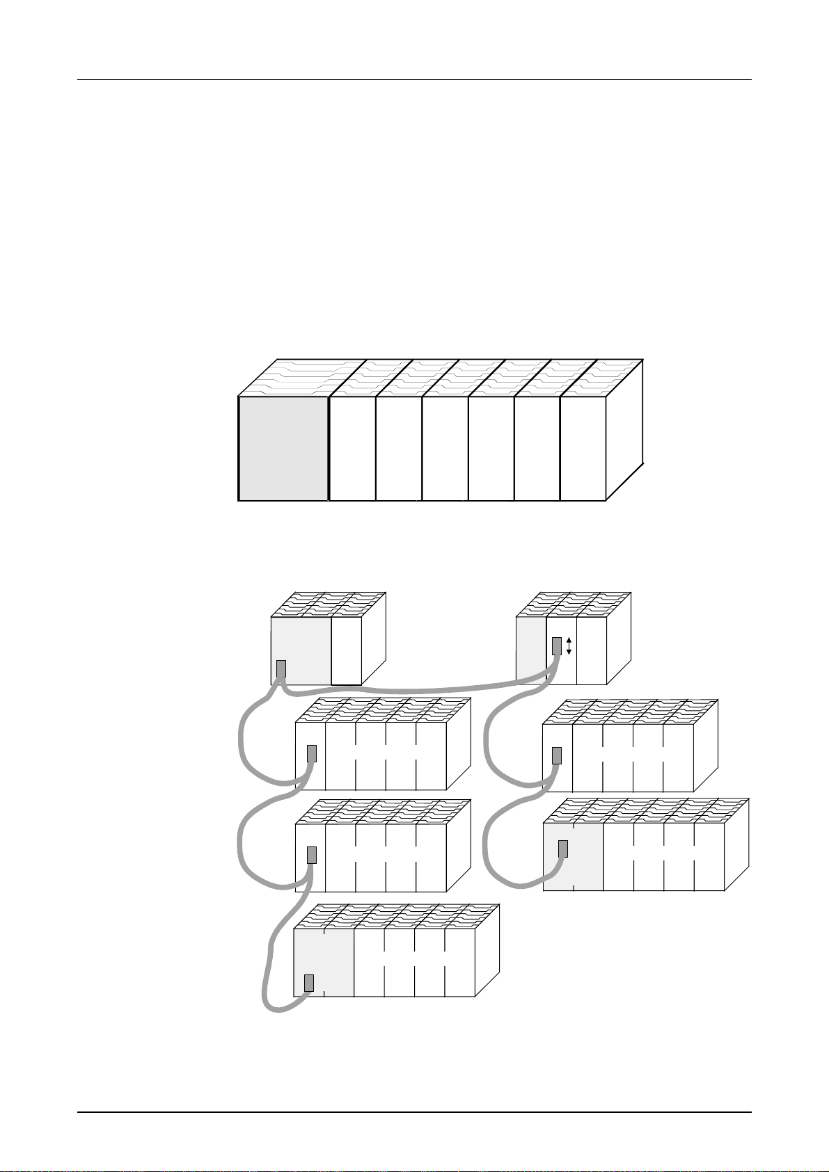
Application fields
With the help of this CPU series you can access the peripher al modules of
the System 300V f rom VIPA. You may request sensors and cont rol actors
via standardized commands and program s. One CPU is able to manage a
maximum of 32 modules in one line.
Application
example
Central compact solution
CPU
CPU 31x
AI 8 AO 2
DIO 16
Decentral system via Profibus
System 300 System 200
CPU 31xDPM
CPU
3, 4, 6
2
DO 16
DO 32
CPU IM 208
DI 32
2,5
IM 353
input/output periphery
2
IM 353
input/output periphery
3
CPU 31x
input/output periphery
4
IM 253
input/output periphery
5
CPU 21x DP
input/output periphery
6
3-6 HB130E - CPU - Rev. 11/50
Page 33
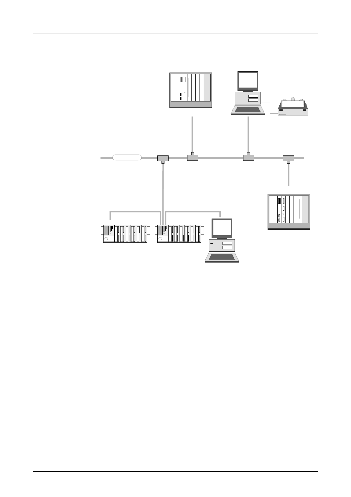
Manual VIPA System 300V Chapter 3 Hardware description
Operation via TCP/IP
VIPA Rack-135U
Visualizat ion an d
shop floor data collection
via OPC-Server
CP 143 TCP/IP
TCP/IP
VIPA Rack-135U
System 300V
CPU31xNET
System 300V
CP 143 TCP/IP
CPU31xNET
HB130E - CPU - Rev. 11/50 3-7
Page 34

Chapter 3 Hardware description Manual VIPA System 300V
System overview
CPU 31x
• Instruction compatible to STEP
®
7 by Siemens
• Configuration via the Siemens SIMATIC Manager
• Integrated 24V Power supply
• MP
2
Interface: MPI (4 st atic / 8 dynamic connections) or serial point-to-
point coupling to the PC
• LEDs for status and diagnostics
• Battery buffer for RAM and clock
• Slot for MMC as external storage medium for programs and data
• Internal Flash ROM for saving the project engineering at battery failure
• Possibility of firmware update via MMC
• Slot for CompactFlash
Type II (only at CP version)
• Integrated controller for the System 300V peripheral modules
• Integrat ed Pr ofibus-DP-Slave
• E/A address range digital/analog 1024Byte
• Work memory 96 ... 512kByte
• Load memory 144 ... 1024kByte
• 256 Timer
• 256 Counter
• 8192 Bit memories
3-8 HB130E - CPU - Rev. 11/50
Page 35
Manual VIPA System 300V Chapter 3 Hardware description
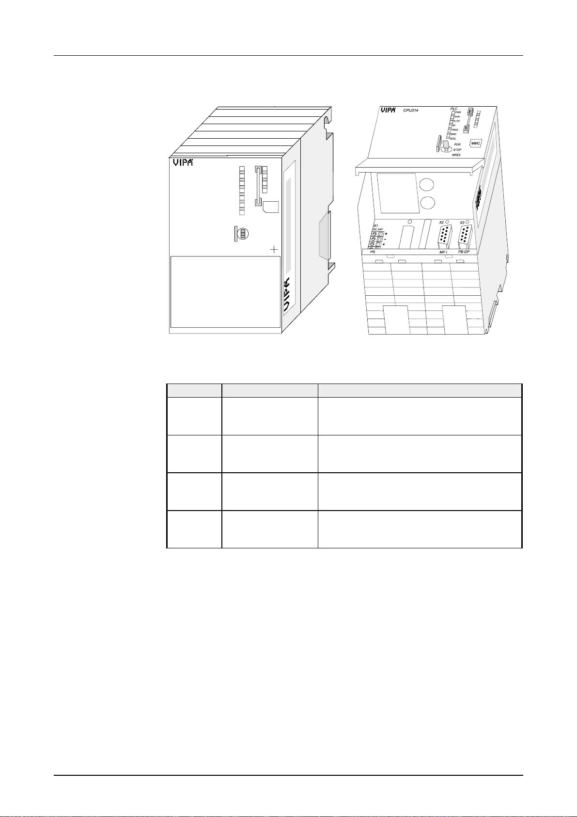
CPU 31x
X1
DC 24V
+
-
+
-
CPU314
PLC
PWR
RUN
STOP
SF
FRCE
MMC
DESL
RUN
STOP
MRES
VIPA 314-1sl01
X2 X3
MMC
X2
3
4
Ordering data
CPU 31x
Type Order number Description
CPU 314 VIPA 314-1SL01 SPS CPU 314 with DP slave
96kB W or k / 144kB Load memory
CPU 315 VIPA 315-1SL01 SPS CPU 315 with DP slave
192kB W or k / 256kB Load memory
CPU 316 VIPA 316-1SL01 SPS CPU 316 with DP slave
256kB W or k / 512kB Load memory
CPU 317 VIPA 317-1SL01 SPS CPU 317 with DP-Slave
512kB W or k-/ 1MB Load memory
HB130E - CPU - Rev. 11/50 3-9
Page 36
Chapter 3 Hardware description Manual VIPA System 300V
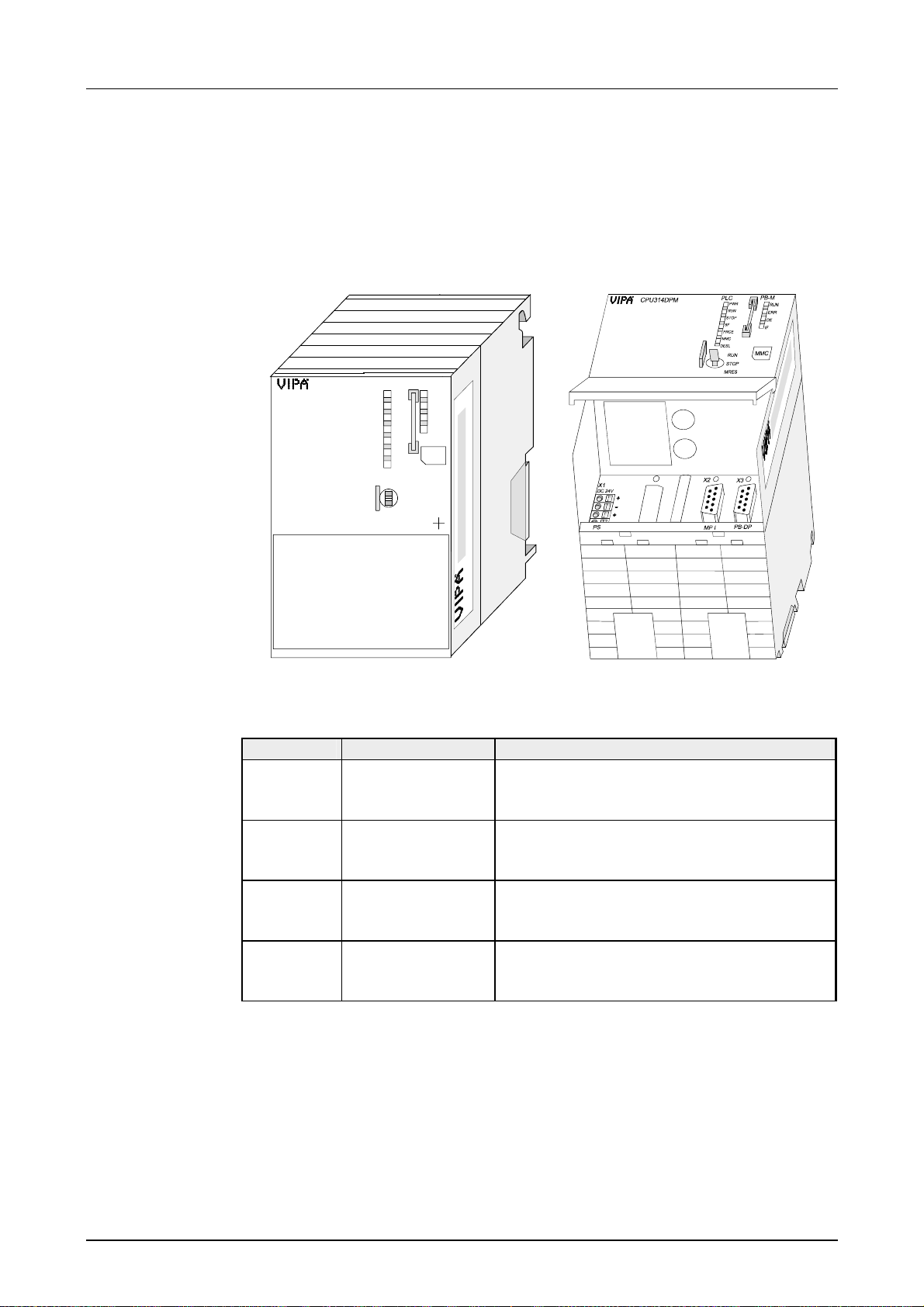
CPU 31xDPM
Like CPU 31x additionally with:
• integrated Profibus- DP m aster with Auto RUN instead of DP slave
• status display for Profibus-DP m ast er
X1
DC 24V
CPU314DPM
X5
+
-
+
-
PLC
PWR
RUN
STOP
SF
FRCE
MMC
DESL
RUN
STOP
MRES
VIPA 314-2DP01
X2 X3
PB-M
MMC
RUN
ERR
DE
IF
X2
3
4
Ordering data
CPU 31xDPM
Type Order number Description
CPU 314 VI PA 314- 2DP01 SPS CPU 314 with DP master
96kB W or k / 144kB Load memory
CPU 315 VI PA 315- 2DP01 SPS CPU 315 with DP master
192kB W or k / 256kB Load memory
CPU 316 VI PA 316- 2DP01 SPS CPU 316 with DP master
256kB W or k / 512kB Load memory
CPU 317 VI PA 317- 2DP01 SPS CPU 317 with DP master
512kB W or k / 1MB Load memory
3-10 HB130E - CPU - Rev. 11/50
Page 37
Manual VIPA System 300V Chapter 3 Hardware description
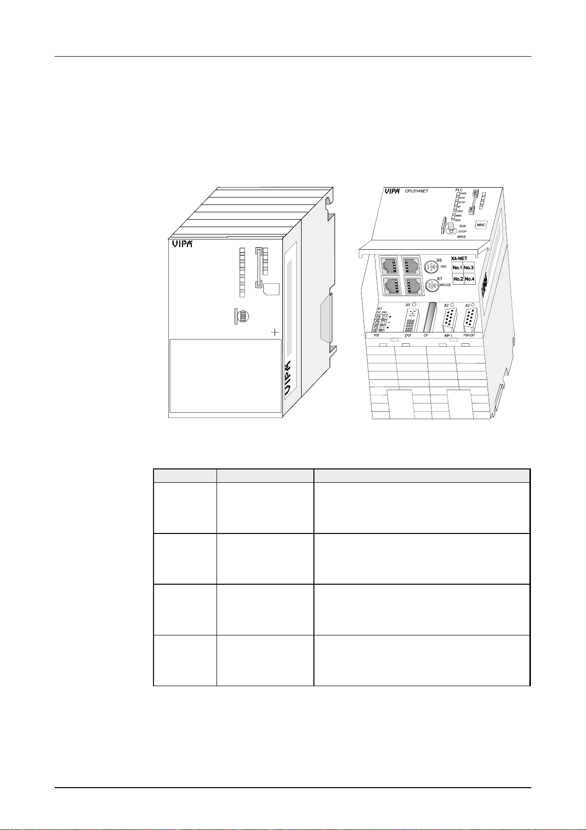
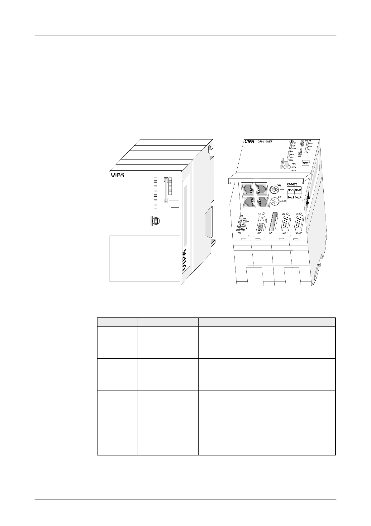
CPU 31xNET
Like CPU 31x additionally with:
• integrated TCP/I P-CP with Auto RUN
• integrated 4port Switch
PLC
PWR
RUN
STOP
SF
FRCE
MMC
DESL
RUN
STOP
MRES
VIPA 314-3SL01
X2 X3
MMC
X2
3
4
X1
DC 24V
CPU314NET
X5
+
-
+
-
Ordering data
CPU 31xNET
Type Order number Description
CPU 314 VI PA 314- 3SL01 SPS CPU 314 with DP slave, Ethernet
TCP/IP-Interface, 4port Switch,
96kB W or k / 144kB Load memory
CPU 315 VI PA 315- 3SL01 SPS CPU 315 with DP slave, Ethernet
TCP/IP-Interface, 4port Switch,
192kB W or k / 256kB Load memory
CPU 316 VI PA 316- 3SL01 SPS CPU 316 with DP slave, Ethernet
TCP/IP-Interface, 4port Switch,
256kB W or k / 512kB Load memory
CPU 317 VI PA 317- 3SL01 SPS CPU 317 with DP slave, Ethernet
TCP/IP-Interface, 4port Switch,
512kB W or k / 1MB Load memory
HB130E - CPU - Rev. 11/50 3-11
Page 38
Chapter 3 Hardware description Manual VIPA System 300V
CPU 31xNET with
DP master
Like CPU 31x additionally with:
• integrated TCP/I P-CP with Auto RUN
• integrated 4port Switch
• integrated Profibus- DP m aster with Auto RUN instead of DP slave
• status display for Profibus-DP m ast er
PLC
CPU314NET
PWR
RUN
STOP
SF
FRCE
MMC
DESL
RUN
STOP
MRES
VIPA 314-3DP01
PB-M
MMC
RUN
ERR
DE
IF
X2
3
4
Ordering data
CPU 31xNET
with DP master
X5
X1
DC 24V
+
-
+
-
X2 X3
Type Order number Description
CPU 314 VI PA 314- 3DP01 SPS CPU 314 with DP master, Ethernet
TCP/IP-Interface, 4port Switch,
96kB W or k / 144kB Load memory
CPU 315 VI PA 315- 3DP01 SPS CPU 315 with DP master, Ethernet
TCP/IP-Interface, 4port Switch,
192kB W or k / 256kB Load memory
CPU 316 VI PA 316- 3DP01 SPS CPU 316 with DP master, Ethernet
TCP/IP-Interface, 4port Switch,
256kB W or k / 512kB Load memory
CPU 317 VI PA 317- 3DP01 SPS CPU 317 with DP master, Ethernet
TCP/IP-Interface, 4port Switch,
512kB W or k / 1MB Load memory
3-12 HB130E - CPU - Rev. 11/50
Page 39
Manual VIPA System 300V Chapter 3 Hardware description
Structure
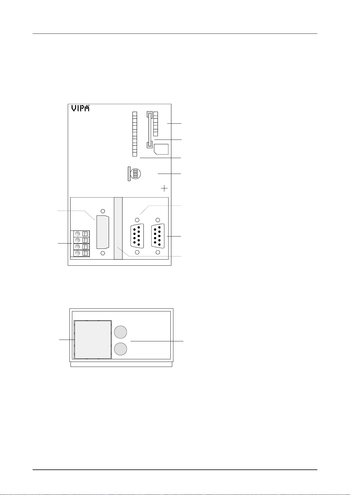
CPU 31x
31x-1SL01
5
X1
DC 24V
6
Underside view
1
PS MP I PB-DP
CPU314
PLC
PWR
RUN
STOP
SF
FRCE
MMC
DESL
RUN
STOP
MRES
VIPA 314-1SL01
X2 X3
MMC
X2
3
[1] deactivated LEDs
[2] MMC slot
1
2
3
4
4
[3] LEDs of the CPU part
[4] Operating mode switch CPU
The following components are under
the front flap
[5] Clipping for DVI slot
[6] Slot for DC 24V Power supply
[7] MP
2
[8] RS485 Pr ofibus interface
7
[9] Clipping for CompactFlash slot
I interface
+
+
-
2
8
9
For later expansions there are places for an Ether net slot res. switch slot,
keyboard and mouse (as PS2-Connection) on the underside of the front
flap:
2
[1] Clipping for Ethernet slot
res. Switch
[2] Clipping for keyboard res.
mouse PS2 slots
HB130E - CPU - Rev. 11/50 3-13
Page 40
Chapter 3 Hardware description Manual VIPA System 300V
P
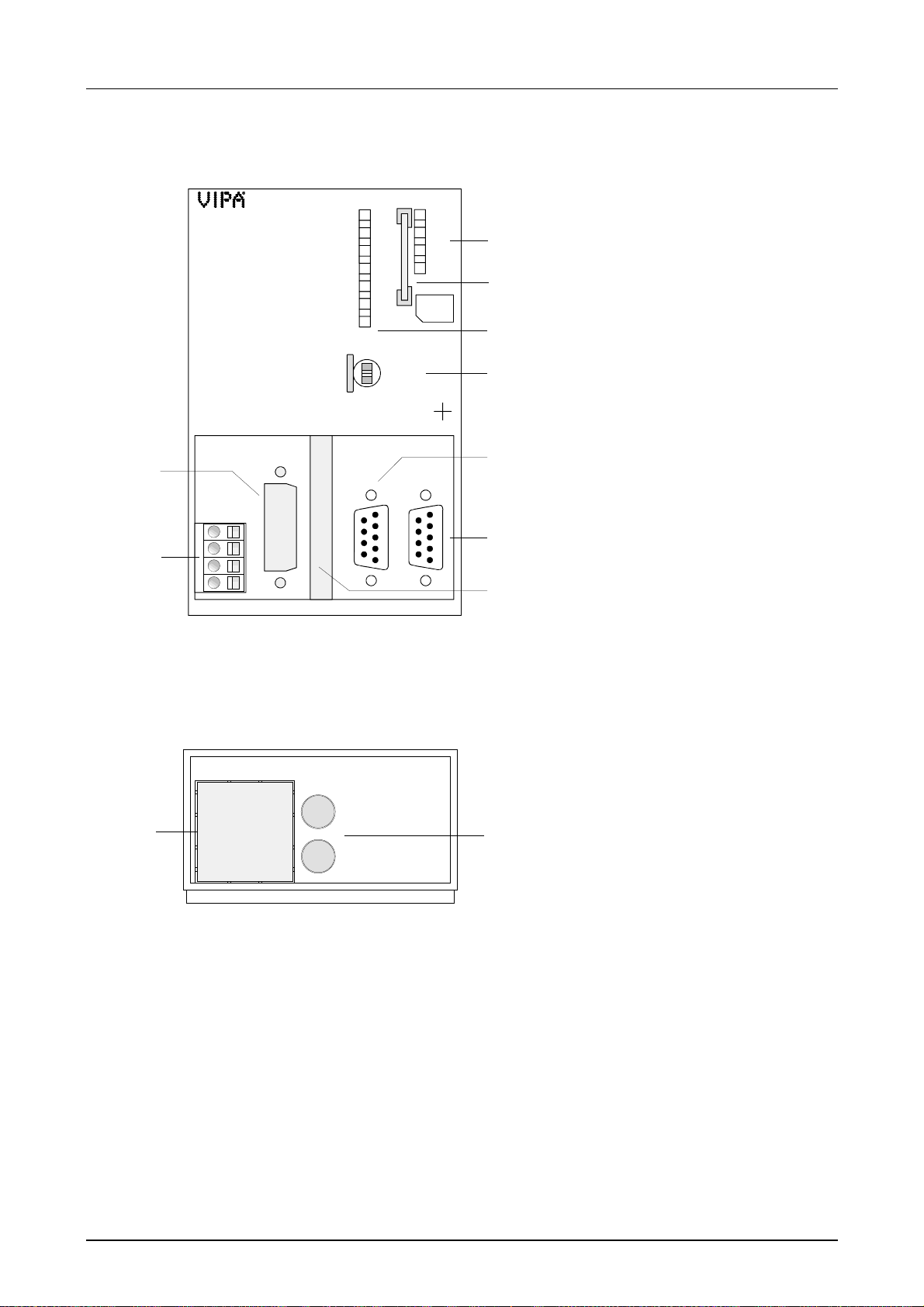
CPU 31xDPM
31x-2DP01
5
X1
DC 24V
6
Underside view
1
CPU314DPM
PLC
PWR
RUN
STOP
SF
FRCE
MMC
DESL
PB-M
RUN
ERR
DE
IF
MMC
RUN
STOP
MRES
VIPA 314-2DP01
X2 X3
+
+
-
PS MP I PB-DP
2
For later expansions there are places for an Ethernet slot res. Switch slot,
keyboard and mouse (as PS2-Connection) on the underside of the front
flap:
X2
3
[1] LEDs of the integrated Profibus D
[2] MMC slot
[3] LEDs of the CPU part
1
[4] Operating mode switch CPU
2
3
4
4
The following components are
under the front flap
[5] Clipping for DVI slot
[6] Slot for DC 24V Power supply
[7] MP
2
I interface
[8] RS485 Pr ofibus interface
[9] Clipping for CompactFlash slot
7
8
9
[1] Clipping for Ethernet slot
res. Switch
[2] Clipping for keyboard res.
2
mouse PS2 slots
3-14 HB130E - CPU - Rev. 11/50
Page 41
Manual VIPA System 300V Chapter 3 Hardware description
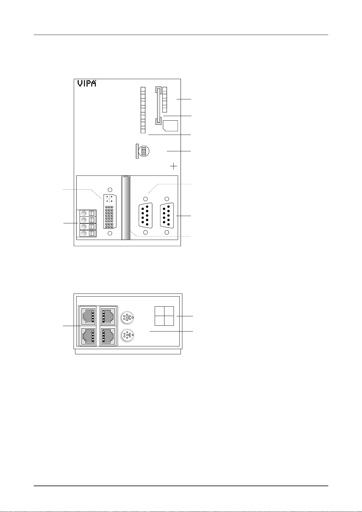
CPU 31xNET
31x-3SL01
5
X1
DC 24V
6
Underside view
X4
1
CPU314NET
X5
PLC
PWR
RUN
STOP
SF
FRCE
MMC
DESL
RUN
STOP
MRES
VIPA 314-3SL01
X2 X3
MMC
+
+
-
PS DVI CF PB-DP
MP I
2
The connections for Ethernet, keyboard and mouse are under a fr ont flap
that you may raise.
X6
KBD
X7
MOUSE
X4-NET
No.1 No.3
No.2 No.4
X2
3
[1] deactivated LEDs
[2] MMC slot
1
[3] LEDs of the CPU part
[4] Operating mode switch CPU
2
3
4
4
The following components are
under the front flap
[5] DVI slot
[6] Slot for DC 24V Power supply
[7] MP
2
I interface
[8] RS485 Pr ofibus interface
7
[9] CompactFlash slot
8
9
[1] 4por t Switch for twisted pair
connection to the Ethernet
2
[2] Assignment of the 4port
Switch
3
[3] Jacks for keyboard res.
mouse
HB130E - CPU - Rev. 11/50 3-15
Page 42
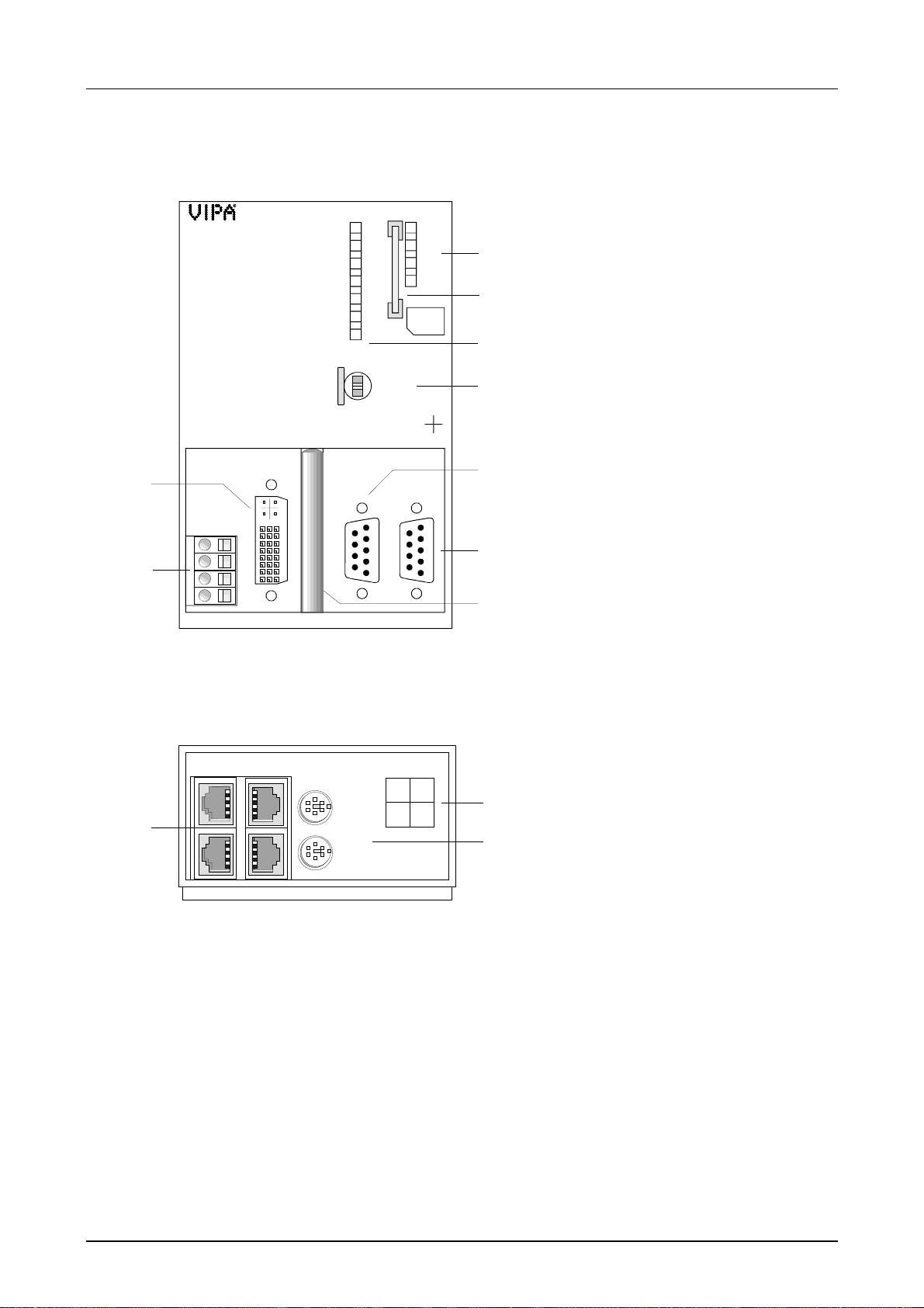
Chapter 3 Hardware description Manual VIPA System 300V
CPU 31xNET
31x-3DP01
5
X1
DC 24V
6
PS DVI CF PB-DP
Underside view
X4
1
CPU315NET
X5
+
+
-
PLC
PWR
RUN
STOP
SF
FRCE
MMC
DESL
RUN
STOP
MRES
VIPA 315-3DP01
X2 X3
2
MP I
PB-M
RUN
ERR
DE
IF
MMC
X2
3
1
2
3
4
4
7
8
9
[1] LEDs of the integrated
Profibus DP master
[2] MMC slot
[3] LEDs of the CPU part
[4] Operating mode switch CPU
The following components are
under the front flap
[5] DVI slot
[6] Slot for DC 24V Power supply
[7] MP
2
I interface
[8] RS485 Pr ofibus interface
[9] CompactFlash slot
The connections for Ethernet, keyboard and mouse are beneath a front
flap that you may raise.
X6
KBD
X7
MOUSE
X4-NET
No.1 No.3
No.2 No.4
2
3
[1] 4port Switch for twisted pair
connection to the Ethernet
[2] Assignment of the 4port
Switch
[3] Jacks for keyboard res.
mouse
3-16 HB130E - CPU - Rev. 11/50
Page 43

Manual VIPA System 300V Chapter 3 Hardware description
Components
LEDs
CPU-Part
To display the status the CPU has two rows of LEDs on t he frontside, one
for the CPU and one for t he Pr ofibus-DP master.
The following tables show you the usage of the LEDs and the according
colors:
Label Color Meaning
PWR yellow CPU-Part is provided with internal 5V
RUN green CPU is in the operating mode RUN
STOP yellow CPU is in the operating mode STOP
SF red blinks at system errors(Hardware-defect)
FRCE yellow blinks as soon as variables are forced (fixed)
MMC yellow blinks at MMC access
DESL yellow shows Profibus DP slave activity, if the integrated
Profibus master is deactivated
Note!
All LEDs of the CPU part are blinking three times, when accessing an
invalid MMC or when the MMC is pulled out during the reading process.
Profibus DP
master part
Name Color Meaning
RUN green Only RUN blinks: the DP master is in RUN. The
DP-Slaves are called and the outputs are 0
("clear"-Status).
RUN+DE are blinking: the DP master is in
"operate"-Status. It Exchanges dat a with the DPSlaves.
ERR red blinks at a slave failure
DE yellow DE (Data exchange) shows communication via
Profibus-DP.
IF red Init err or at wrong parametrization.
HB130E - CPU - Rev. 11/50 3-17
Page 44
Chapter 3 Hardware description Manual VIPA System 300V
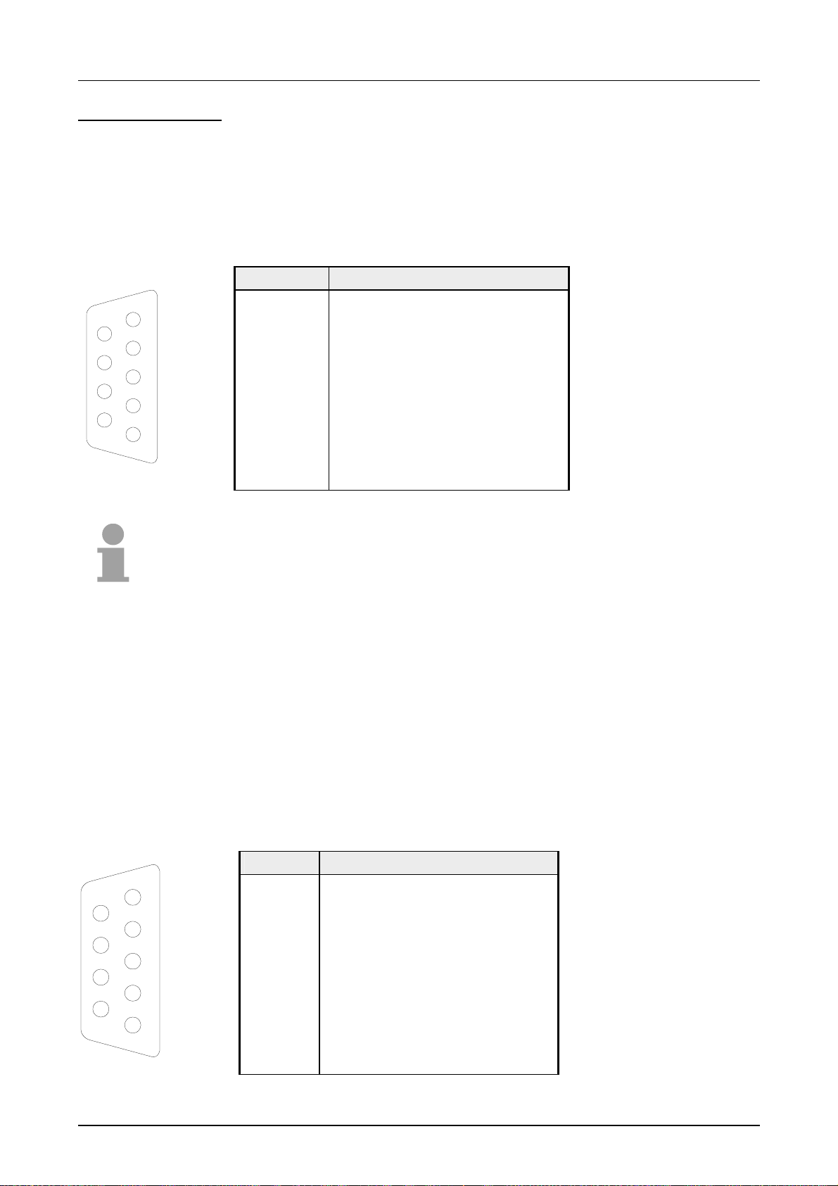
Jacks and Plugs
Profibus-interface
PB DP
5
9
4
8
3
7
2
6
1
The recent CPU includes the following jack s res. plugs:
Via the 9pin RS485-interface you link up the int egr ated Pr of ibus-DP m aster
to your Profibus network. The RS485 jack has the following pin
assignment:
9pin jack
Pin Occupation
1 Shield
2 n.c.
3 RxD/TxD-P (Line B)
4 RTS
5 M5V
6 P5V
7 n.c.
8 RxD/TxD-N (Line A)
9 n.c.
Note!
Please make sure to activate the terminating resistors at the bus ends!
2
Interface
MP
2
The MP
I interface handles the data exchange bet ween CPU and PC. Via
a bus communication you may transfer applications and data between the
CPUs that are connected via MPI.
For a serial transfer from your PC you normally need a MPI transducer.
Alternatively you may use the "Green Cable" (Order No. : 950-0KB00). fr om
VIPA, that allows a serial connection without transducer. The "Green
Cable" may only be used directly and exclusively at CPUs with MP
2
I
interface. Please also regard the hints in the chapter "Deployment CPU
31x"!
2
The MP
I jack has the following pin assignm ent :
9pin jack
Pin Assignment
5
9
4
8
3
7
2
6
1
1 reserved (do not connect )
2 M24V
3 RxD/TxD-P (Line B)
4 RTS
5 M5V
6 P5V
7 P24V
8 RxD/TxD-N (Line A)
9 n.c.
3-18 HB130E - CPU - Rev. 11/50
Page 45
Manual VIPA System 300V Chapter 3 Hardware description
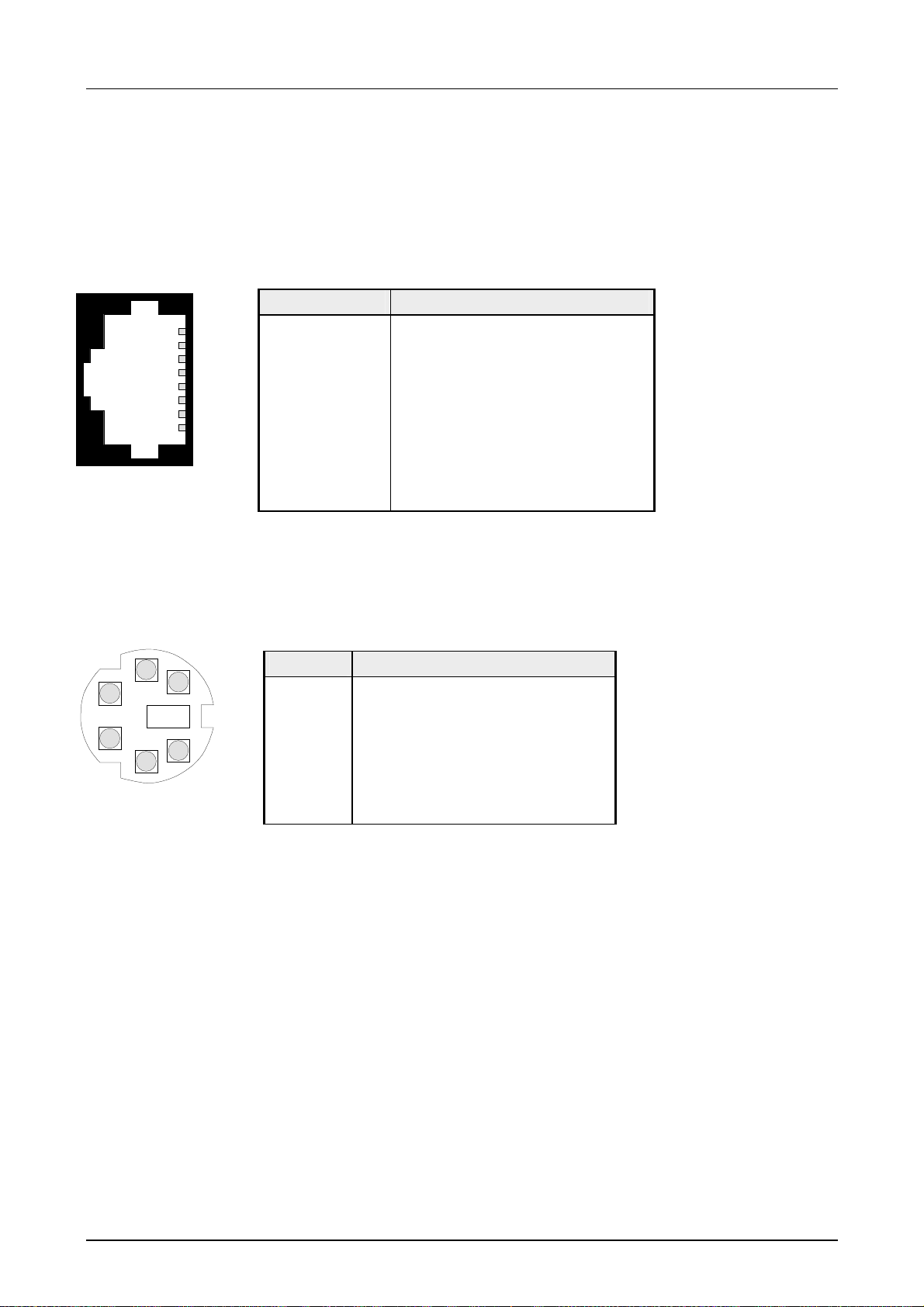
EthernetConnection
PS2 jack
KBD/MOUSE
3
1
2
4
The twisted-pair jacks are used to build-up a twisted-pair network in star
topology. This allows you to connect up to 4 Ethernet components, where 1
connection has to be deployed as uplink port to the ongoing network. The
uplink port is detected automatically.
This jack has the following pin assignment:
8pin RJ45 jack:
Pin Signal
1
2
3
4
5
6
7
8
1 Transmit +
2 Transmit 3 Receive +
4 5 6 Receive 7 8 -
The pin assignment of the two PS2 jacks is identical. Connect your
keyboard to the jack marked with "KBD" and your mouse to the jack
marked with "MOUSE".
Pin Assignment
5
1 + KBD-Data (I/O)
2 reserved
6
3 GND
4 +5V
5 + KBD-Clock (I/O)
6 reserved
HB130E - CPU - Rev. 11/50 3-19
Page 46
Chapter 3 Hardware description Manual VIPA System 300V
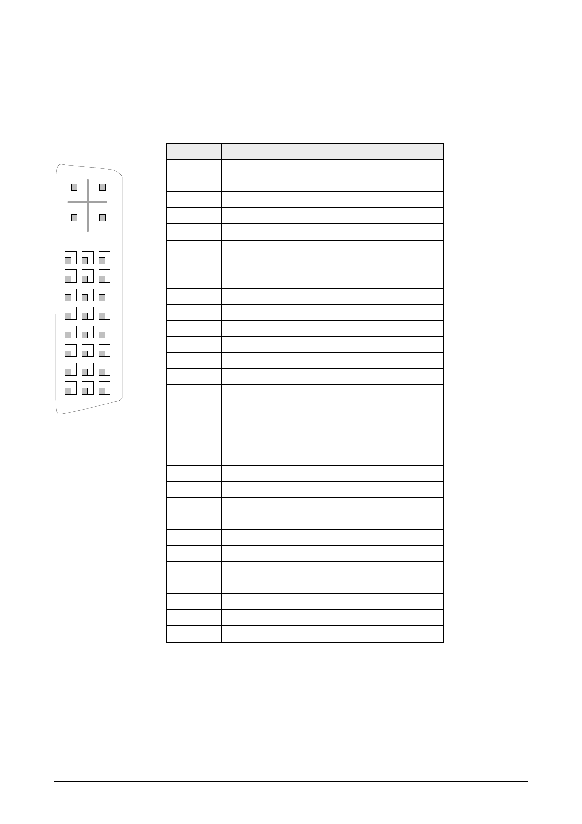
DVI jack
C2
C1
16
8
7
6
5
4
3
2
1
9
C4
C5
C3
24
23
22
21
20
19
18
17
The DVI jack is suitable f or analog and digital displays and monitors with a
max. resolution of 1280x1024pixel.
The jack has the following pin assig nm ent :
Pin Signal
C1 Analog Red
C2 Analog Green
C3 Analog Blue
C4 Analog Horizontal Sync
C5 Analog RGB Return
1 T.M.D.S Data22 T.M.D.S Data2+
3 T. M.D.S Data2/4 Shield
4 T.M.D.S Data45 T.M.D.S Data46 DDC Clock
7 DDC Data
8 Analog Ver t ical Sync
9 T.M.D.S Data110 T.M.D.S Data1+
11 T.M.D.S Data1/3 Shield
12 T.M.D.S Data313 T.M.D.S Data3+
14 +5V Power
15 Ground (return for +5V, HSync and VSync)
16 Hot Plug Detect
17 T.M.D.S Data018 T.M.D.S Data0+
19 T.M.D.S Data0/5 Shield
20 T.M.D.S Data521 T.M.D.S Data5+
22 T.M.D.S Clock Shield
23 T.M.D.S Clock+
24 T.M.D.S Clock-
3-20 HB130E - CPU - Rev. 11/50
Page 47

Manual VIPA System 300V Chapter 3 Hardware description
Memory of the
CPU
The following storage t echnologies are deployed at the CPU 31x:
Memory Type Description
Load memory battery
buffered RAM
Here is the battery buff ered program code and data block s also
in off-state.
Work memory RAM During program execution, the program code and data blocks
are stored in the work memory.
Internal Flash Flash-ROM With a copy command you may store the program code and
data blocks in the internal Flash-ROM. A read access happens
only at empty buffer battery.
MMC Flash-ROM External memory card for project engineering of CPU and DP
master and for f irmware update of CPU, DP master and CP.
With a copy command you may store the program code and
data blocks from t he CPU to MMC.
CompactFlash
Flash-ROM
The CompactFlashis only used with the CPU 31xNET and
serves as external data memory.
Load memory
The load memory is a battery buffer ed RAM where the program code and
data blocks are stored during project engineering.
Work memory
Internal Flash
MultiMediaCard
"MMC"
After power-on of the CPU, it transfer s the program code and data blocks
from the load memory in the unbuffered work memory.
In addition to t he load memory, every CPU 31x has an internal Flash-RO M.
With the Copy-RAM-to-ROM command in the STEP
7 Manager from
Siemens, the program code and data blocks are transferred to the internal
Flash-ROM and stored permanently.
An access to the data in the internal Flash-ROM happens only at empty
buffer batt ery after boot-up when no MMC is plugged-in.
The Multi Media Card, in short MMC, is an external memory module and
can be ordered via the order no.: VIPA 953- 0KX10.
CPU, CP and Profibus-DP master may use the CPU simultaneously for
project engineering and firmware update.
The MMCs are preformatted with the file system FAT16. With every
common MMC reading device, the MMC is linked-up to your PC as external
drive. This allows to create progr ams at the PC, to copy them onto MMC
and transfer them t o the VIPA CPU by plugging-in the MMC.
More detailed information is to find in the chapter "Deployment CPU 31x"
CompactFlash
Type II
As soon as a PC ( CPU 31xNET) is integrated, it uses a CompactFlash of
the type I or II for the external data storage.
This slot for the CompactFlash
is marked with "CF".
HB130E - CPU - Rev. 11/50 3-21
Page 48

Chapter 3 Hardware description Manual VIPA System 300V
Power supply
X1
DC 24V
+
-
+
-
PS
Battery backup for
clock and RAM
The CPU has an integrated power supply. The power supply has to be
provided with DC 24V (20,4 ... 28,8V). For this serves the double DC 24V
slot, that is underneath the flap.
Due to the double slot you may directly deduct DC 24V from the not used
connection pair for front provided modules.
Via the power supply not only the internal electronic is provided with
voltage, but by means of the backplane bus also the connected
System 300V modules.
The internal power supply may be strained with maximum 3.5A.
The internal electronic is galvanically connected with the supply voltage.
The power supply is protected against polarity inversion and overvoltage.
A rechargeable battery is installed on every CPU 31x to safeguard the
contents of t he RAM when power is removed. This battery is also used to
buffer the int ernal clock.
The rechargeable bat tery is maintained by a charging circuit that receives
its power from the internal power supply and that maintain the clock and
RAM for a max. period of 30 days.
Operating mode
switch
RUN/STOP/MRES
With t he operating mode switch you may switch the CPU between STOP
and RUN. The operating mode START is driven automatically from the
CPU between STOP and RUN.
Placing the switch to Memory Reset (MRES), you request an overall reset.
3-22 HB130E - CPU - Rev. 11/50
Page 49

Manual VIPA System 300V Chapter 3 Hardware description
Technical Data
CPU 31x
General
Electrical Data VIPA 314 ... VIPA 317
Power supply DC 24V
Current consumption max. 1.1A
Dissipation power max. 2W
Status display (LEDs) via LEDs on the frontside
Integrated Profibus-interface DP slave
Slots / Interfaces:
2
I
MP
Profibus
Battery buffer / clock yes / Lithium-Battery, 30 Days Buffer
Output voltage to backplane bus max. 3.5A
Bit memory 8192
Timers / Counters 256 / 256
Modules FBs 1024, FCs 1024
Combination with peripheral modules
Max. number of modules 32
Max. digital E/A (I/O) 32
Max. analog E/A (I/O) 16
Addressable E/A (I/O)
digital channels
analog channels
Measurements and Weight
Measurements (HxWxL) in mm 80x125x120
Weight in g 200g
2
I-interface for data transmission:
MP
4 static / 8 dynamic connections(187kBaud)
RS232: 38,4kBaud
RS485 Profibus-DP slave
DBs 2047
1024
1024
Module Specific
CPU 314 CPU 315 CPU 316 CPU 317
Program memory 96kByte 192kByte 256kByte 512kByte
Load memory 144kByte 256kByte 512kByte 1MB
Typical processing
0.18 / 0.78 0.18 / 0.78 0.18 / 0.78 0.18 / 0.78
time Bit/Word
(ms/k commands)
Order No.: VIPA 314-1SL01 VI PA 315-1SL01 VIPA 316-1SL01 VIPA 317-1SL01
HB130E - CPU - Rev. 11/50 3-23
Page 50

Chapter 3 Hardware description Manual VIPA System 300V
CPU 31xDPM
Electrical Data VIPA 314 ... 317
Like CPU 31x additionally with
DP master
Status display (LEDs) like CPU 31x additionally with LEDs for the Profibus-DP
Profibus interf ace
Connection 9-pin SubD-slot
Network topology linear bus, active bus termination at both ends, tap line
Medium isolated drilled twisted pair-cable, isolation may be left
Transfer rate 9.6kBaud to 12MBaud
Total length without repeater 100m at 12Mbaud,
Max. number of partners 32 stations in every segment without repeater;
Measurements and Weight
Measurements (WxHxL) in mm 80x125x120
Weight 200g
master
possible
depending on environmental conditions.
with repeater up to 1000m
with Repeater expandable to 126.
Module Specific
CPU 314DPM CPU 315DPM CPU 316DPM CPU 317DPM
Program memory 96kByte 192kByte 256kByte 512kByte
Load memory 144kByte 256kByte 512kByte 1MB
Typical processing
time
Bit/W ord (ms/k
commands)
Order No.:
with DP slave
0.18 / 0.78 0.18 / 0.78 0.18 / 0.78 0.18 / 0.78
VIPA 314-2DP01 VIPA 315-2DP01 VIPA 316-2DP01 VIPA 317-2DP01
3-24 HB130E - CPU - Rev. 11/50
Page 51

Manual VIPA System 300V Chapter 3 Hardware description
CPU 31xNET
Electrical Data VIPA 314 ... 317
Like CPU 31x additionally:
Ethernet TCP/IP Interface
4port Switch
DVI-slot when expanded to Ethernet
Memory
CompactFlash
Ethernet Interface
Network topology 4port Switch, RJ45 for Twisted-Pair-Ethernet
Medium Twisted Pair
Transfer Rate 10/100MBit
Total length max. 100m per Segment
Measurements and Weight
Measurements (WxHxL) in mm 80x125x120
Weight 200g
Module Specific
CPU 314NET CPU 315NET CPU 316NET CPU 317NET
Program memory 96kByte 192kByte 256kByte 512kByte
Load memory 144kByte 256kByte 512kByte 1MB
Typical processing
0.18 / 0.78 0.18 / 0.78 0.18 / 0.78 0.18 / 0.78
time Bit/Word (ms/k
commands)
Order number
VIPA 314-3SL01 VIPA 315-3SL01 VIPA 316-3SL01 VIPA 317-3SL01
with DP-Slave
Order No. with
VIPA 314-3DP01 VIPA 315-3DP01 VIPA 316-3DP01 VIPA 317-3DP01
DP-Slave/Master
HB130E - CPU - Rev. 11/50 3-25
Page 52

Chapter 3 Hardware description Manual VIPA System 300V
3-26 HB130E - CPU - Rev. 11/50
Page 53

Manual VIPA System 300V Chapter 4 Deployment CPU 31x
Chapter 4 Deployment CPU 31x
Outline
Content
This chapter describes the deployment of a CPU 31x together with the
peripheral modules of the System 300V. The description applies to those
modules that have been inserted together with the CPU on one profile rail
and are connected via the backplane bus.
Besides commissioning and start-up behavior you will find here also a
description of the project engineering, parameterization, operating modes
and test functions.
This information also basically applies to the deployment of the CPU 31x
with integrated communication part.
Topic Page
Chapter 4
Fast introduction...................................................................................4-2
Hints for the deployment of the MPI interface.......................................4-4
Installation............................................................................................4-5
Start-up behavior..................................................................................4-6
Addressing...........................................................................................4-7
Project engineering..............................................................................4-9
Parameter adjustment CPU ...............................................................4-12
Project transfer...................................................................................4-13
Operating modes................................................................................4-19
Overall Reset .....................................................................................4-20
Firmware update................................................................................4-22
VIPA specific diagnostic entries.........................................................4-25
Using test functions for the control and monitoring of variables..........4-27
Deployment CPU 31x......................................................4-1
Note!
This informat ion is valid for all the CPUs described in this manual, since the
HB130E - CPU - Rev. 11/50 4-1
back panel communication between the CPU and the peripheral modules is
the same for all models of CPU!
Page 54

Chapter 4 Deployment CPU 31x Manual VIPA System 300V
Fast introduction
Compatibility
Connection to
Profibus-DP
The System 300V CPU is instruction compatible to the programming
language STEP
®
7 from Siemens and may be programmed via the
SIMATIC manager from Siemens.
A large function library is delivered in this package.
Note!
For programming of a System 300V CPU from VIPA please use always the
CPU 315-2DP (6ES7 315-2AF03) from Siemens in the hardware catalog.
For the project engineering, a thorough knowledge of the hardware
configurator from Siemens is required!
When using t he System 300V as intelligent slave, the configuration works
via the hardware configurator by Siemens by means of "configured
stations" as CPU 31x.
The configurat ion of the opt ional integ rat ed Prof ibus m aster t ak es place via
the hardware configurator f rom Siemens. T he project may be saved on the
MMC.
Deployment of the
CP part of the
CPU 31xNET
MultiMediaCard
as external
storage medium
The CP integrated in the CPU 31xNET is projected by WinNCS. The
project engineering may be executed online via Ethernet or offline by
means of a MMC.
The CP supports PU/OP functionality for up to 64 participants and is
accessible by the "PLC" functions via Ethernet.
WinNCS allows you to execute a firmware update online and password
protected or to reboot the CP par t independently from the CPU.
The access rights to the CP are restricted by means of IP list that are
transferred at proj ect engineering.
With an invalid CP pr oject engineer ing , the pr oject at t he CP is deleted and
the CP reboots with the default IP address.
Firmware and project engineering are stor ed at a DOC (DiscOnChip).
CPU, CP and Profibus master use the MultiMediaCard (MMC) as external
storage medium. The MMC is available from VIPA.
With an O verall r eset , it is automatically read from MMC.
4-2 HB130E - CPU - Rev. 11/50
Page 55
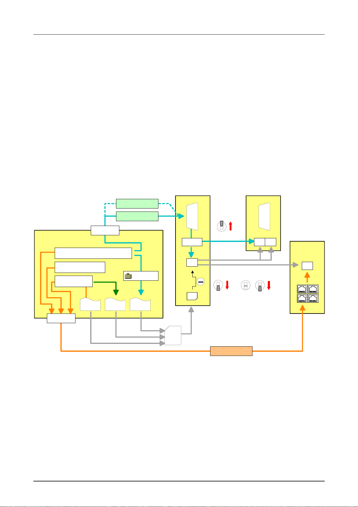
Manual VIPA System 300V Chapter 4 Deployment CPU 31x
Green Cable
Integrated
power supply
Access options for
project engineering
and firmware update
PC
For project engineering of your DP slave you may transfer your projects
from your PC to the CPU serial via MPI by using the "Green Cable". Please
also regard the hints to the Gr een Cable in this chapter.
Every CPU res. bus coupler comes with an integrat ed power supply. The
power supply has to be supplied with DC 24V. By means of the supply
voltage, the bus coupler electronic is supplied as well as the connected
modules via backplane bus. Please reg ar d t hat the integrated power supply
may supply the backplane bus with max. 3.5A.
The power supply is protected against inverse polarity and overcurrent.
The following overview shows all access options for project engineering
and firmware update.
CPU DP-Master
MPI Adapter
Green Cable
MP2I
CPU
RN
DP
RS232
Power ON
Proj.
RAM
Firmw.Proj.
Flash
CP
Hardware Configurator
SIMATIC Manager
from Siemens
WinNCS
firmware
ncs file wld file
RJ45
System data
MMC
Project engineering/Firmware
RAM
MMC
RN
Overall_Reset
ST
MR
Proj./Firmw.
3Sec.
Ethernet
Tip
Proj./Firmw.
DOC
TP
TP
TP TP
HB130E - CPU - Rev. 11/50 4-3
Page 56
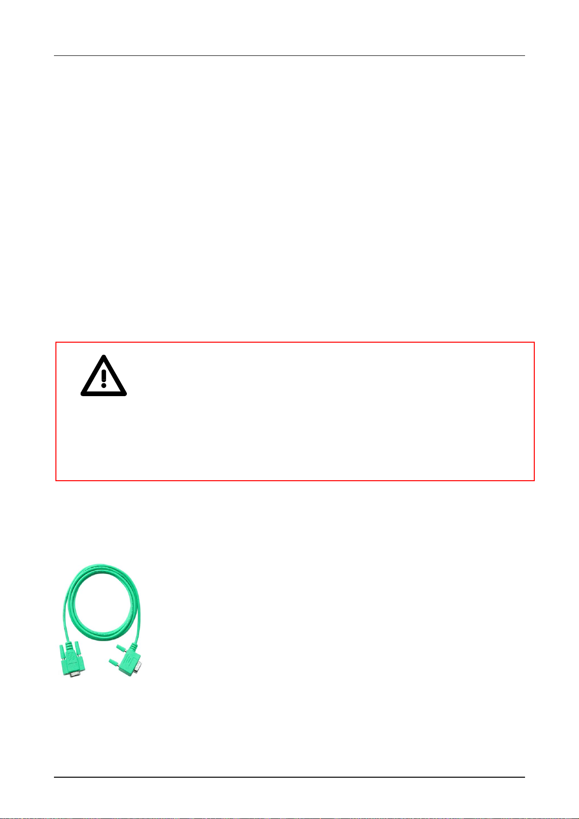
Chapter 4 Deployment CPU 31x Manual VIPA System 300V
Hints for the deployment of the MPI interface
2
What is MP2I?
The MP
• MPI interface
• RS232 interface
Please regard that the RS232 functionality is only available by using the
Green Cable from VIPA.
I jack combines 2 interf aces in 1:
Deployment as
MPI interface
Deployment as
RS232 interface only
via "Green Cable"
The MP interface provides the data transf er between CPUs and PCs. In a
bus communication you may transfer programs and data between the
CPUs interconnected via MPI.
Connecting a common MPI cable, the MPI jack supports the full MPI
functionality.
Important notes for the deployment of MPI cables!
Deploying MPI cables at the CPUs from VIPA, you have to mak e sure that
Pin 1 is not connected. This may cause transfer problems and in some
cases damage the CPU!
Especially Profibus cables from Siemens, like e.g. the 6XV1 830-1CH30,
must not be deployed at MP
2
I jack.
For damages caused by nonobservance of these notes and at improper
deployment, VIPA does not take liabilit y!
For the serial data transfer from your PC, you normally need a MPI
transducer. Fortunately you may also use the "Green Cable" from VIPA.
You can order this under the order no. VI PA 950-0KB00.
The "Green Cable" supports a serial point-to-point connection for data
transfer via the MP
2
I jack exclusively for VIPA CPUs.
4-4 HB130E - CPU - Rev. 11/50
Page 57
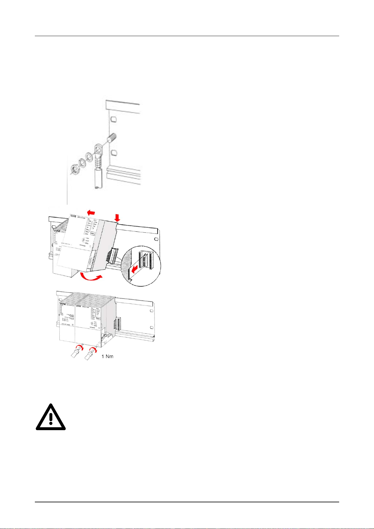
Manual VIPA System 300V Chapter 4 Deployment CPU 31x
Installation
Approach
• Bolt the profile rail with the background (screw
size: M6), so that you still have minimum 65mm
space above and 40mm below the profile rail.
• If the back ground is a grounded metal or device
plate, please look for a low-impedance connection between profile rail and backgr ound.
• Connect the profile rail with the protected earth
conductor. For this purpose there is a bolt with
M6-thread.
• The minimum cross-section of the cable to the
protected earth conductor has to be 10mm
2
.
• Stick the power supply to the profile r ail and pull it
to the left side to t he grounding bolt of the pr ofile
rail.
• Fix the power supply by screwing.
• Take a bus coupler and click it at the CPU from
behind like shown in the picture.
• Stick the CPU to the profile rail right from the
power supply and pull it to the power supply.
• Click the CPU downwards and bolt it like shown.
• Repeat this procedure with the peripheral
modules, by clicking a backplane bus coupler,
stick the module right from the modules you've
already fixed, click it downwards and connect it
with the backplane bus coupler of the last module
and bolt it.
More details see chapter "Cabling and installation specificat ions"
Danger!
• Before installing or overhauling the System 300V, the power supplies
must be disconnected from voltage (pull the plug or remove the fuse)!
• Installation and modifications only by properly trained personnel!
HB130E - CPU - Rev. 11/50 4-5
Page 58
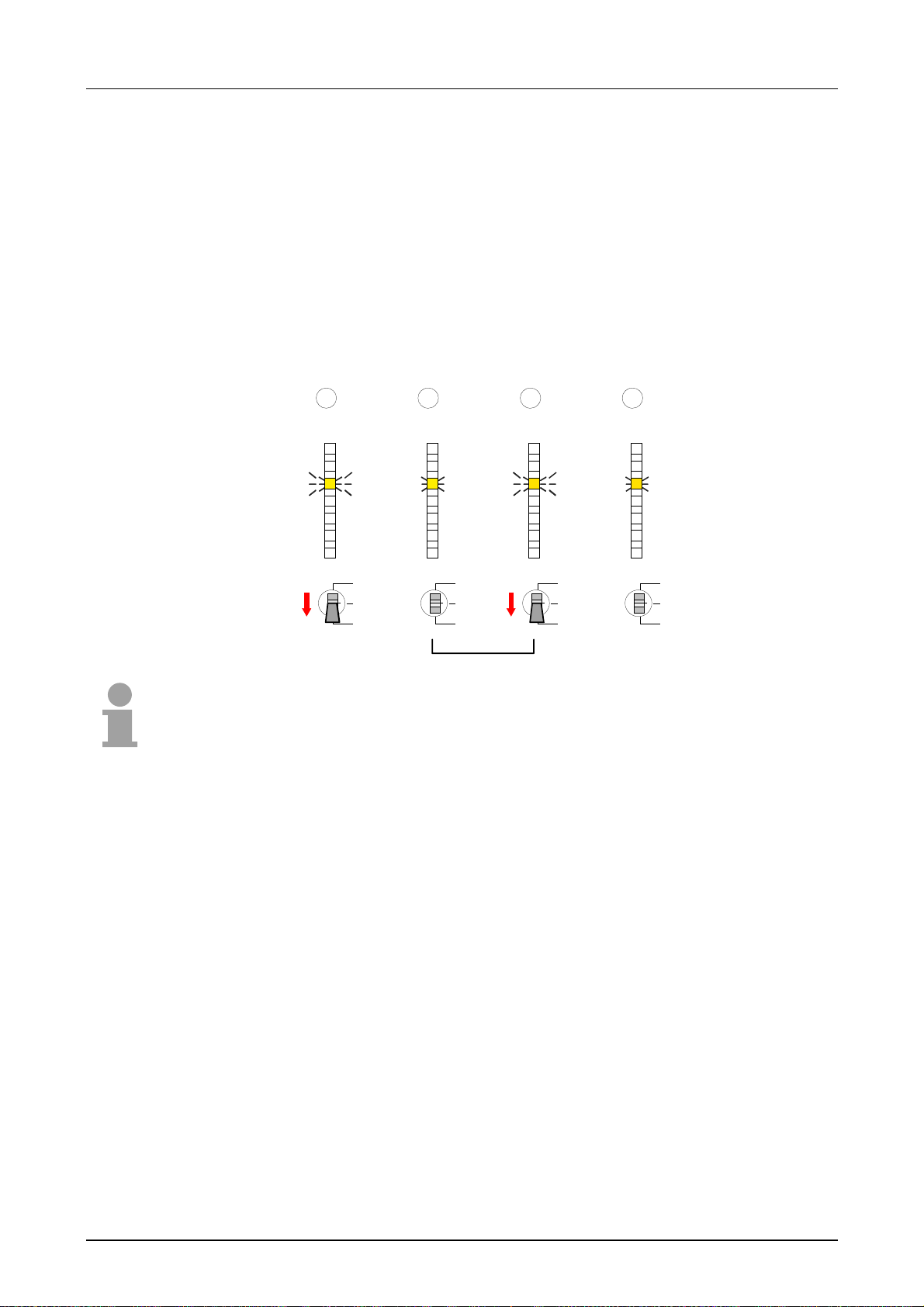
Chapter 4 Deployment CPU 31x Manual VIPA System 300V
Start-up behavior
Turn on power
supply
After the power supply has been switched on, the CPU changes to the
operating mode the operating m ode lever shows.
Now you may transfer your project to the CPU via MPI from your
configuration t ool res. plug in a MMC with your project and run an Overall
reset.
Overall reset
Default boot
procedure, as
delivered
The following picture shows the approach once more:
1 2 3 4
3 Sec.
PLC
PWR
RUN
STOP
SF
FRCE
MMC
DESL
RUN
STOP
MRES
PLC
PWR
RUN
STOP
SF
FRCE
MMC
DESL
RUN
STOP
MRES
3 Sec.
PLC
PWR
RUN
STOP
SF
FRCE
MMC
DESL
RUN
STOP
MRES
PLC
PWR
RUN
STOP
SF
FRCE
MMC
DESL
RUN
STOP
MRES
Note!
The transfer of the application program from the MMC into the CPU takes
always place after an Overall reset!
When the CPU is delivered it has been reset. After a STOP
→RUN
transition the CPU switches to RUN without progr am .
Boot procedure with
valid data in the CPU
The CPU switches to RUN with the program st ored in the battery buffer ed
RAM.
Boot procedure
with empty battery
The accumulator/battery is automatically loaded via the integrated power
supply and guarantees a buffer f or max. 30 days. If this time is exceeded,
the accu may be totally discharged. This means that the battery buffered
RAM is deleted.
In this state the CPU executes an Overall reset. If a MMC is plugged in, the
application on the MMC is transferred into the RAM. Otherwise the CPU
accesses the application in the internal Flash and transf ers this one to the
RAM.
Depending on the chosen operating mode, t he CPU switches to RUN res.
remains in STOP.
This event is stored in the diagnostic buffer as: "Start Overall reset
automatically (unbuffer ed POWER_ON)" .
4-6 HB130E - CPU - Rev. 11/50
Page 59
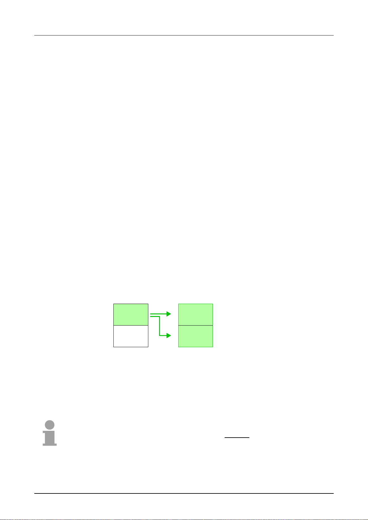
Manual VIPA System 300V Chapter 4 Deployment CPU 31x
Addressing
Automatic
addressing
Up to 32 modules
in one row
Signal states in
the process image
To provide specific addressing of the installed peripheral modules, certain
addresses must be allocated in the CPU.
The CPU contains a peripheral area (addresses 0 ... 1023) and a process
image of the inputs and the outputs (for every address 0 ... 127).
When the CPU is init ialized, it automatically assigns peripheral addresses
to the digital input/output m odules starting from 0.
When no hardware project engineering is available, analog modules are
stored at the automatic address allocation on even addresses start ing with
128.
In the hardware configurator from Siem ens you may parameterize maximum
up to 8 modules per row. When using the System 300V CPUs from VIPA you
may control up to 32 modules by distributing the modules you want to
parameterize on the first 8 Plug-ins. Although the modules that are behind on
the profile rail are not visible, they are included into the addressing range of
the CPU by means of the automatic addressing.
The signal states of the lower addresses (0 ... 127) are additionally saved
in a special memory area called the
process image.
The process image this divided into two parts:
• process image to the inputs (PAE)
• process image to the outputs (PAA)
Peripheral area
0
.
.
Digital modules
.
127
128
.
Analog modules
.
.
1023
Process image
0
.
.
.
127
0
.
Outputs
.
.
127
Inputs
PAE
PAA
The process image is updated automatically when a cycle has been
completed.
Read/write access
You may access the modules by means of r ead or write operations on the
peripheral bytes or on the process image.
Note!
Please remember that you can access diff erent modules by means of read
and write operations on the same address.
Digital and analog modules have separate address r anges at the aut omat ic
address allocation.
Digital modules: 0 ... 127, Analog modules: 128 ... 1023
HB130E - CPU - Rev. 11/50 4-7
Page 60
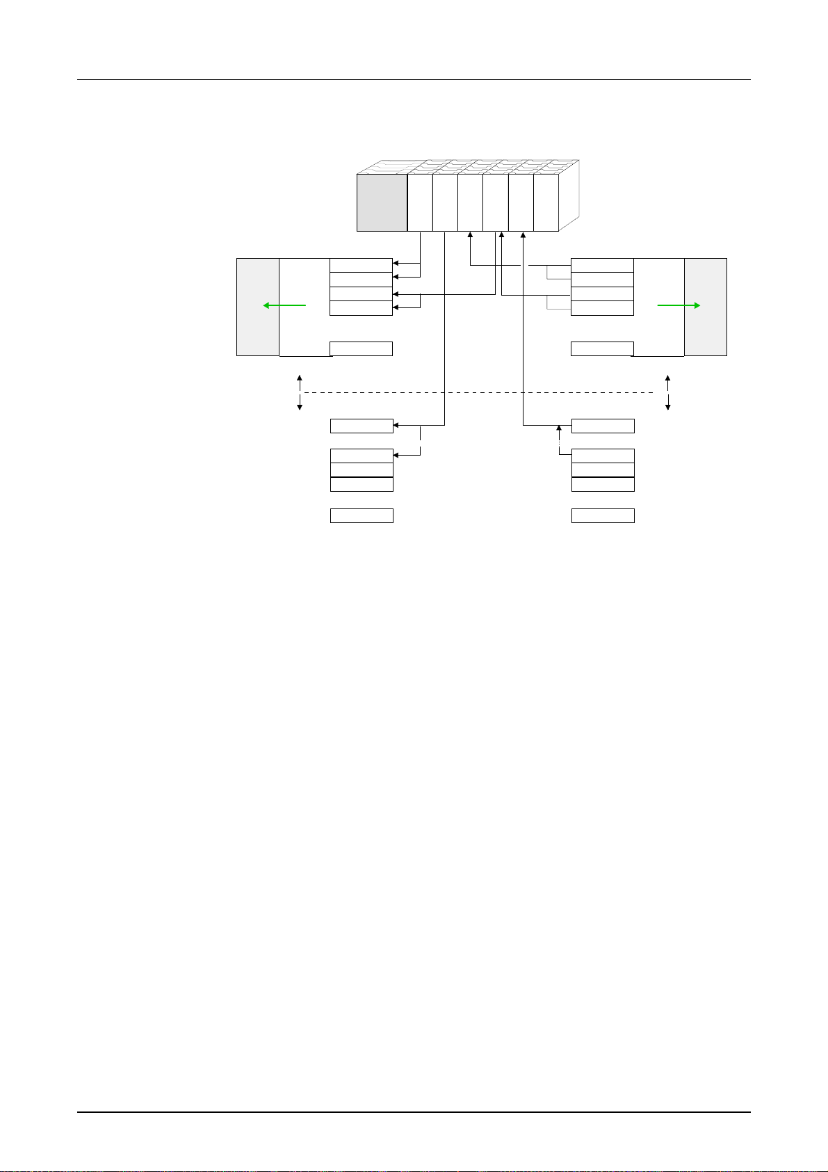
Chapter 4 Deployment CPU 31x Manual VIPA System 300V
Example for the
automatic address
allocation
The following figure illust rates the automatic address allocation:
PAE
rel. Adr. Peripheral area
0
Input byte 0
1
Input byte 1
2
Input byte 2
3
Input byte 3
.
.
.
127
digital
analog
128
.
.
.
143
144
145
.
.
.
1023
.
.
.
Input byte 127
Input byte 0
Input byte 15
Input byte 16
Input byte 17
Input byte 1023
Slot no.: 1 2 3 4 5 6
CPU 31x
.
.
.
.
.
.
AI 8x12Bit
DI 16xDC24V
.
.
.
DO 16xDC24V
DIO 16xDC24V
AO 4x12Bit
Peripheral area rel. Adr
Output byte 0
Output byte 1
Output byte 2
Output byte 3
.
.
.
Output byte 127
Output byte 0
.
.
.
Output byte 7
Output byte 8
Output byte 9
.
.
.
Output byte 1023
1023
0
1
2
3
.
.
.
127
digital
analog
128
.
.
.
135
136
137
.
.
.
PAA
Change address
allocation by
project
engineering
You may change the address allocation with the help of the SIMATIC
manager from Siemens at any time. This allows you to get also analog
modules into the process image area (0 ... 127) and digital modules above
address 127.
The preparation for the project engineering and the approach are
described on the following pages.
4-8 HB130E - CPU - Rev. 11/50
Page 61

Manual VIPA System 300V Chapter 4 Deployment CPU 31x
Project engineering
Overview
To be compatible to the Siemens SIMATIC manager, you have to configure the System
300V CPUs from VIPA as
Profibus address
1 is reserved
The description below ref ers to modules t hat are at the same bus tog ether
with the CPU 31x from VIPA.
In order to address the installed peripheral modules individually, specific
addresses in the CPU have to be assigned to them.
The allocation of addresses and the config uration of the installed modules
is a function of the Siemens SI MATIC manager.
The project engineering of the CPU 31x, the Profibus components and
System 300V modules from VIPA happens in the Siemens SIMATIC
manager.
The parameterization of t he Ethernet com ponents tak es place via the VIPA
parameterization tool WinNCS.
With the help of the VIPA Green Cable you may transfer your project from
the PC into the CPU via the MPI interface.
You may also copy your project with a common MMC reading device to a
MMC and transfer it into the CPU by means of an Overall reset.
CPU 315-2DP (6ES7 315-2AF03 V1.2)!
Please regard that t he Profibus address 1 is reserved for t he system. You
should not use the address 1!
Fast introduction
HB130E - CPU - Rev. 11/50 4-9
• Start Siemens SIMATIC manager with new project and configure
Siemens CPU 315-2DP (6ES7 315-2AF03 V1.2). The CPUs 31x from
VIPA have to be included into the hardware configurator from Siemens
as
CPU 315-2DP (6ES7 315-2AF03 V1.2).
• The modules are linked-up in the plugged-in sequence starting with
slot 4.
• Via double click on the CPU or the modules you may parameterize
them.
• When deploying a CPU 31xDP with a master system t he CPU can be
connected as slave system CPU 31x by means of "configured stations".
A condition is that the slave system was projected before.
• Save and transfer your project.
In the following these points are more near described.
Page 62
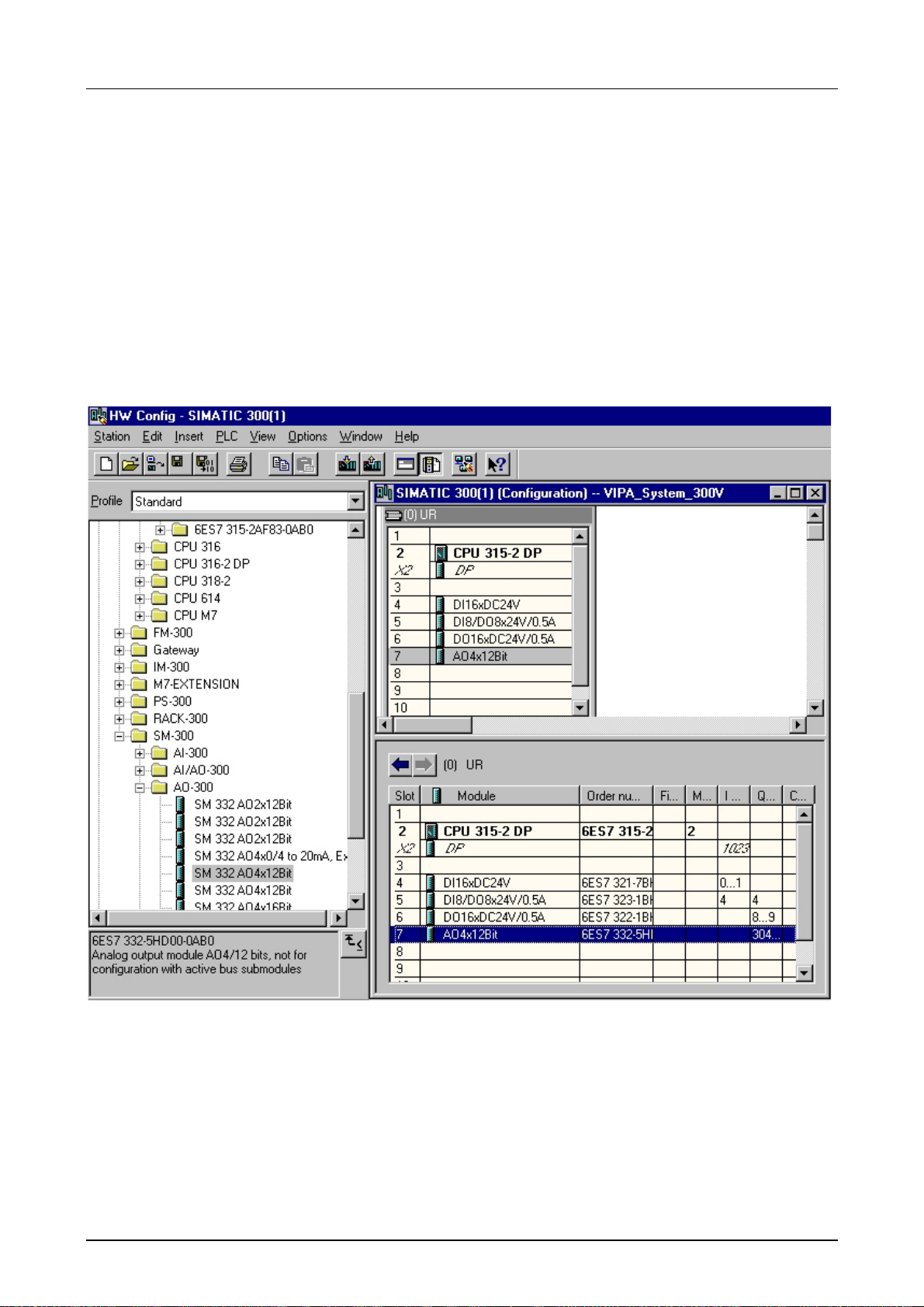
Chapter 4 Deployment CPU 31x Manual VIPA System 300V
Approach of the
project
engineering
This is the approach to configur e the modules that are on the bus beside
the CPU:
• Create a new project.
• Add the CPU 315-2DP (6ES7 315-2AF03-0AB0 V1.2) from the
hardware catalog.
You will find this at
• Link-up your System 300V modules in the plugged-in sequence starting
Simatic 300 > CPU 300 > CPU 315-2 DP.
with slot 4.
• If needed, parameterize the CPU res. the modules. The parameter
window appears as soon as you double click on the according module.
• Save your project.
4-10 HB130E - CPU - Rev. 11/50
Page 63
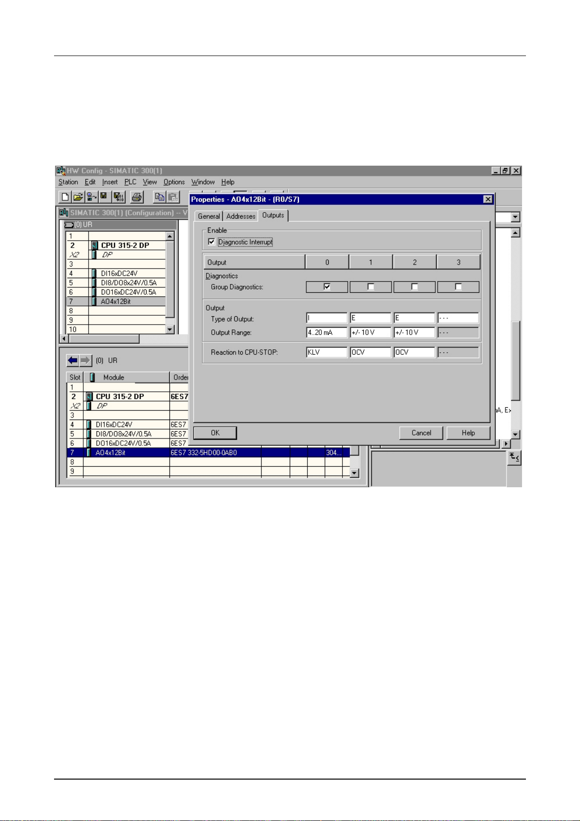
Manual VIPA System 300V Chapter 4 Deployment CPU 31x
Parameterization
of modules
System 300V modules are able to receive parameter data f rom the CPU.
Via deployment of the SIMATIC manager from Siemens you may define
parameters for param et erizable System 300V modules at any time.
Therefore you double- click at the placed module you want to paramet erize.
In the now opening dialog window the parameters can be changed.
Transfer project
The data transmission e.g. takes place via MPI. If your programming
system don't has a MPInterface, you may use the Green cable f rom VIPA
to establish a serial point-to-point connect ion.
The "Green Cable" has t he order number VIPA 950-0KB00 and may only
be used with VIPA CPUs with MP
2
I interface.
• Connect your PG with the CPU
• With PLC > Upload Station in your conf iguration tool you transfer your
project into the CPU.
• Plug in a MMC and transfer your application program to the MMC with
PLC > Copy RAM to ROM.
• During the write process, the "MMC"-LED at the CPU is blink ing. Due to
system reasons, the ready write process is announced a little bit too
soon. The write process is only finished when the LED extinguishes.
HB130E - CPU - Rev. 11/50 4-11
Page 64
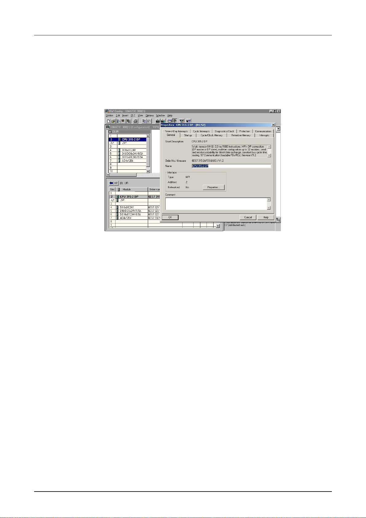
Chapter 4 Deployment CPU 31x Manual VIPA System 300V
Parameter adjustment CPU
Outline
Approach
Supported
parameters
The general parameter s concerning the CPU section of your System 300V
have to be configured in t he hardware configurator from Siemens under the
properties of the CPU 315-2 DP.
With a double click at the CPU 315-2 DP you reach the parameterization
window for your CPU. Via the register tabs you may access all parameters
of your System 300V CPU.
Please regard, that at t his t im e not all parameters are supported.
The following parameters are evaluated by the CPU at this time:
General:
MPI address of the CPU
Baud rate (19.2kBaud, 187k Baud)
maximum MPI address
Startup:
Startup when expected/actual
configuration dif fer
"Finished" message by modules
Transfer of par am eters to modules
Retentive memory:
Number of Memory bytes
starting with MB0
Number of S7 Timers starting
with T0
Number of S7 Counters start ing
with C0
Protection:
Level of protection ...password
Time-of-Day Interrupts:
OB10: active
execution
start date
time-of-day
Cyclic Interrupts:
OB35: execution
Cycle Clock Memory:
Scan Cycle monitoring time
Scan Cycle load from
communication
OB85: Call up at I/O access error
Clock bit memory with memory
byte no.
4-12 HB130E - CPU - Rev. 11/50
Page 65
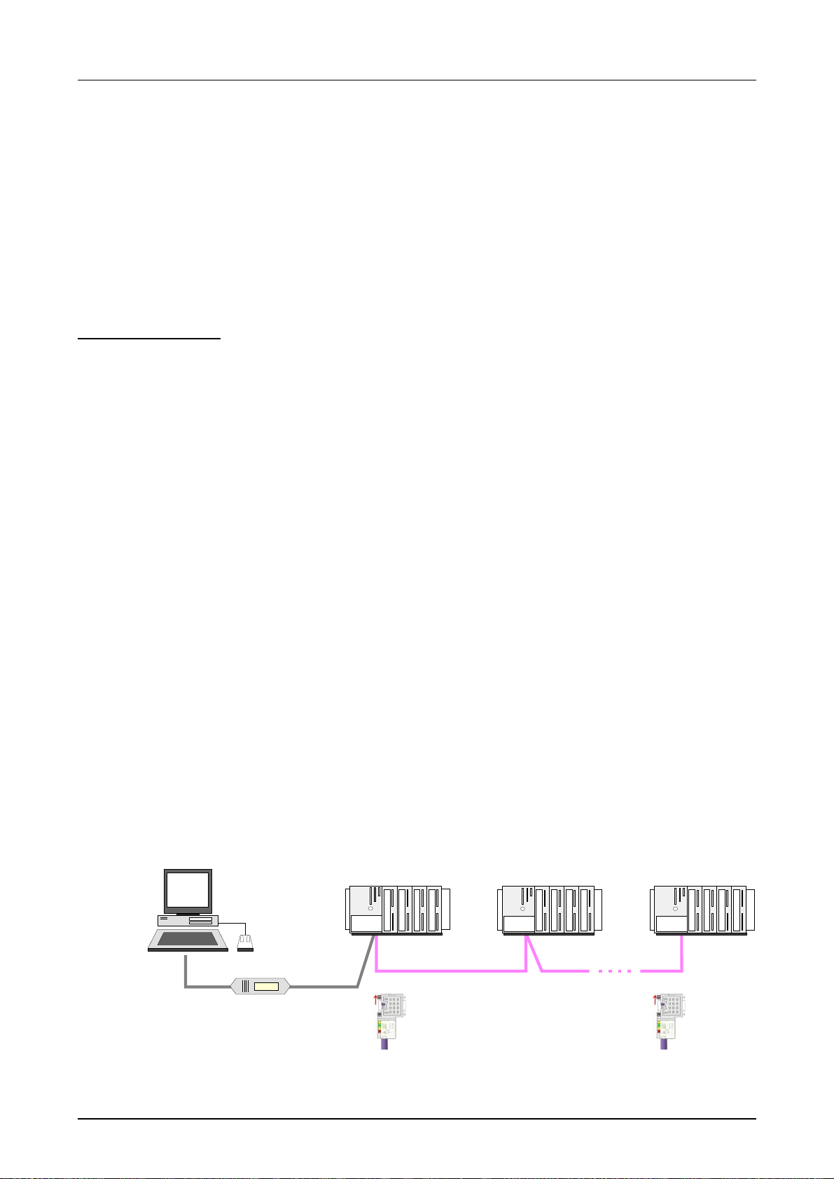
Manual VIPA System 300V Chapter 4 Deployment CPU 31x
Project transfer
Overview
Transfer via MP2I
resp. Profibus
Transfer with MPI
Programming
cable via MP
resp. Profibus
Terminating resistor
2
I
There are 3 possibilities for t he transfer of your proj ect into the CPU:
• Transfer via MP
2
I
• Transfer via Profibus (not for startup)
• Transfer via MMC by using a card reader
• Transfer via Ethernet (only CPU 31xNET)
Depending upon CPU 31x you have the following transfer options:
• Transfer via MPI Programming cable (MPI/Profibus Communication)
• Transfer via Green Cable (Serial Communication via MP
2
I - not
Profibus)
The MPI programming cables are available at VIPA in different variants.
The employment of the cables is identical. The cables provide a bus
enabled RS485 plug for the MP
2
I jack of the CPU and a RS232 res. USB
plug for the PC.
Due to the RS485 connection you may plug the MPI programming cables
directly to a already plugged MPI plug on the MP
2
I jack. Every bus
participant identifies itself at the bus with an unique MPI address, in the
course of which the address 0 is reserved for prog ramming devices. The
structure of a MPI net is in the principal identical with the structure of a
1.5MBaud Profibus net. I.e. the sam e rules are valid and you use the same
components for the build-up. The single participants are connected with
each other via bus interface plugs and Profibus cables. Your CPU 31x
supports transfer rates of up to 1.5MBaud. Per default the MPI net runs
with 187.5kBaud. VIPA CPUs are delivered with MPI address 2.
A cable has to be terminated with its surge impedance. For this you switch
on the terminating resistor at the first and the last participant of a network
or a segment.
Please make sure that the participants with the activated terminating
resistors are always provided with voltage during start-up and operat ion.
STEP7
from Siemens
MPI programming cable
Terminating
MPI-/Profibus net
Terminating
HB130E - CPU - Rev. 11/50 4-13
Page 66

Chapter 4 Deployment CPU 31x Manual VIPA System 300V
Approach transfer
via MP
2
I
Approach transfer
via Profibus
A maximum of 32 PG/OP connections is supported by MPI. The transfer
via MPI takes place with the following proceeding:
• Connect your PC to the MPI jack of your CPU via a MPI programming
cable.
• Load your project in the SIMATIC Manager fr om Siemens.
• Choose in the menu Options > Set PG/PC interface
• Select in the according list the "PC Adapter (MPI)"; if appropriate you
have to add it first, then click on [Properties].
• Set in the register MPI the transfer parameters of your MPI net and type
a valid
address.
• Switch to the register Local connection
• Set the COM port of the PCs and the transf er rate 38400Baud for the
MPI programming cable fr om VIPA.
• Via PLC > Load to module you may transfer your project via MPI to the
CPU and save it on a MMC via
PLC > Copy RAM to ROM if one is
plugged.
Transfer via Profibus is only available by DP master, if project ed as master
and assigned with a Profibus address before. A maximum of 31 PG/OP
connections is supported by Profibus. The tr ansf er via MPI takes place with
the following proceeding:
• Connect your PC to the MPI jack of your CPU via a MPI programming
cable.
• Load your project in the Siemens SIMATIC Manager.
• Choose in the menu Options > Set PG/PC interface
• Select in the according list the "PC Adapter (Profibus)"; if appropriate
you have to add it first, then click on [ Pr operties].
• Set in the register Profibus the transf er paramet ers of your Profibus net
and type a valid
Profibus address. The Profibus address must be
assigned to the DP master by a project before.
• Switch to the register Local connection
• Set the COM port of the PCs and the transf er rate 38400Baud for the
MPI programming cable fr om VIPA.
• Via PLC > Load to module you may transfer your proj ect via Profibus to
the CPU and save it on a MMC via
PLC > Copy RAM to ROM if one is
plugged.
4-14 HB130E - CPU - Rev. 11/50
Page 67
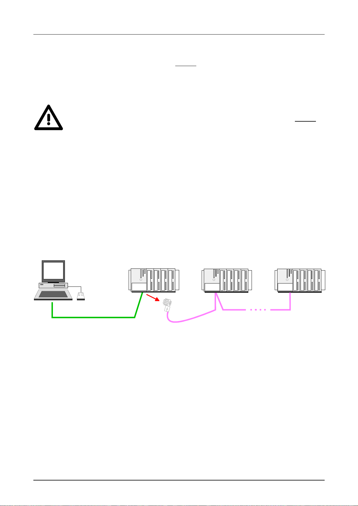
Manual VIPA System 300V Chapter 4 Deployment CPU 31x
Transfer with
Green Cable only
2
at MP
I
Approach
The "Green Cable" is a programming and download cable that may
exclusively be plugged directly
plugging the Green Cable to a MP
connection between the COM interface of your PC and the MP
to VIPA components with MP2I jack. By
2
I jack you may establish a serial
2
I interface
of your CPU.
Attention!
Please regard that you may plug the "Green Cable" exclusively directly to
the MP
2
I interfaces of VIPA-CPUs!
• Connect the PC and CPU with the Green Cable.
• Load your project in the SIMATIC Manager fr om Siemens.
• Choose in the menu Options > Set PG/PC interface
• Select in the according list the "PC Adapter (MPI)"; if appropriate you
have to add it first, then click on [Properties].
• Switch to the register Local connection
• Set the COM port of t he PCs and the transfer rate 38400Baud for the
MPI programming cable from VIPA. The settings in the register
MPI are
ignored at the usage of the Green Cable.
• Via PLC > Load to module you may transfer your project to the CPU
and save it on a MMC via
PLC > Copy RAM to ROM if one is plugged.
STEP7
from Siemens
Green Cable
MPI net
HB130E - CPU - Rev. 11/50 4-15
Page 68

Chapter 4 Deployment CPU 31x Manual VIPA System 300V
Hints for the
Green Cable
The Green Cable is a gr een connection cable, manufactured exclusively for
the deployment at VIPA System components.
The Green Cable is a programming and download cable for VIPA CPUs
2
MP
I jack and VIPA fieldbus masters. The Green Cable from VIPA is
available under the order no. VIPA 950-0KB00.
The Green Cable allows you to:
• transfer projects serial
Avoiding high hardware needs (MPI transducer, etc.) you may realize a
serial point-to-point connection via the Green Cable and the MP
2
I jack.
This allows you to connect components to your VIPA-CPU t hat are able
to communicate serial via an MPI adapter like e.g. a visualization
system.
• execute firmware updates of the CPUs and f ieldbus masters
Via the Green Cable and an upload application you may update the
firmware of all recent VIPA CPUs with MP
2
I jack and certain fieldbus
masters (see Note).
Important notes for the deployment of the Green Cable
Nonobservance of the following notes may cause damages on system
components.
For damages caused by nonobservance of the following notes and at
improper deployment, VIPA does not take liability!
Note to the application area
The Green Cable may exclusively deployed directly at the concerning jacks
of the VIPA components (in between plugs are not permitted). E.g. a MPI
cable has to be disconnected if you want to connect a Green Cable.
At this time, the following components support Green Cable:
VIPA CPUs with MP
2
I jack and fieldbus masters from VIPA.
Note to the lengthening
The lengthening of the Green Cable with another Green Cable res. The
combination with further MPI cables is not permitted and causes damages
of the connected components!
The Green Cable may only be lengthened with a 1:1 cable (all 9 Pins are
connected 1:1).
4-16 HB130E - CPU - Rev. 11/50
Page 69

Manual VIPA System 300V Chapter 4 Deployment CPU 31x
Transfer via
MMC
Transfer
MMC→
→RAM→→→→ROM
→→
Transfer
RAM→→→→MMC→→→→ROM
Transfer control
As external storage medium a MMC is deployed. The MMC (Memory Card)
serves as external transfer medium f or programs and firmware for, among
others, it provides the PC compatible FAT16 file system. With an overall
reset or PowerON the MMC is automatically read. There may be stored
several projects and sub-directories on a MMC storage module. Please
consider that the curr ent project is stored in t he root directory and has one
of the in the following described file names.
Always after overall reset and PowerON the CPU tries to load a user
program from the MMC into the battery-buffered RAM or in the Flash
memory. Here the following file names may be assigned to the project
depending upon the desired functionality:
• S7PROG.WLD
After overall reset the user program S7PROG.WLD is transferred into
the battery-buffered RAM.
• S7PROGF.WLD (starting with Firmware-Versi on V. 3.8.6)
After overall reset the user program S7PROG.WLD is transferred into
the battery-buffered RAM and additionally into the Flash memory. An
access to the Flash memory takes only place at empty battery of the
buffer and when no MMC with user program is plugged-in.
• AUTOLOAD.WLD
After PowerON the user program AUTOLOAD.WLD is transferred into
the battery-buffered RAM.
When the MMC has been plugged-in, the write command stores the
content of the battery-buffered RAM as
write command is controlled by means of the Siemens hardware
configurator via
"MMC"-LED of the CPU is blinking. When the LED expires the write
process is finished. Simult aneously a write process into the internal Flash
memory of the CPU takes place.
After a write process onto the MMC, an according ID event is written into
the diagnostic buffer of the CPU. To monitor the diagnosis entries, you
select
the register "Diagnostic Buffer" you reach the diagnosis window.
The following events may occur:
More information to the event IDs may be found at the end of this chapter.
Note!
If the size of the user applicat ion exceeds the user memory of the CPU, the
content of the MMC is not transferred to the CPU.
Execute a compression before the transfer, for this does not happen
automatically.
PLC > Module Information in the Siemens SIMATIC Manager. Via
Event-ID Meaning
0xE100 MMC access error
0xE101 MMC error file system
0xE102 MMC error FAT
0xE200 MMC writing finished
0xE300 Internal Flash writing finished
PLC > Copy RAM to ROM. During the write process the
S7PROG.WLD at the MMC. The
HB130E - CPU - Rev. 11/50 4-17
Page 70

Chapter 4 Deployment CPU 31x Manual VIPA System 300V
Transfer via
Ethernet
Besides of the transfer via MPI res. MMC you may configure the CPU via
the CP portion when using the CPU 31xNET.
Here all block functions are supported like e.g. load, alter, monitor and
save blocks.
All "PLC" functions except of "Har dware diag nosis" are available.
Up to 64 participants may access simultaneously.
Preconditions
The following software packag es are installed:
- SIMATIC manager from Siemens V.5.1 or V.5.2 with SP1
- SIMATIC NET
Approach
•
Start the SIMATIC manager f rom Siemens, load your proj ect and select
the wanted interface for the online driver under
Interface
• Choose an interface par am eterization that refers t o your net work PCI card
like e.g.:
TCP/IP->3Com EtherLink 10/100 PCI
• Transfer the wanted blocks and system data via the PLC functions into
your CPU.
More detailed information is to be f ound at chapter "Deployment CPU 31x
with TCP/IP" at "PG/OP communication".
.
Options > PG/PC
4-18 HB130E - CPU - Rev. 11/50
Page 71

Manual VIPA System 300V Chapter 4 Deployment CPU 31x
Operating modes
Outline
Operating mode
STOP
The CPU can be in one of 3 operating modes:
• Operating mode STOP
• Operating mode START -UP
• Operating mode RUN
Certain conditions in t he operating modes START-UP and RUN require a
specific reaction from the system program. In this case the application
interface is often provided by a call to an organization block that was
included specifically for this event.
• The application program is not processed.
• If there has been a processing before, the values of counters, timers,
flags and the process image are retained during the transition to the
STOP mode.
• Outputs are inhibited, i.e. all digital outputs are disabled.
• RUN-LED off
• STOP-LED on
Operating mode
START-UP
Operating mode
RUN
• During the transit ion from STOP to RUN a call is issued t o the start-up
organization block OB 100. The length of this OB is not limited. The
processing time f or this O B is not monit ored. The st art -up OB m ay issue
calls to other blocks.
• All digital outputs are disabled during the start-up, i.e. outputs are
inhibited.
• RUN-LED blinks
• STOP-LED off
When t he CPU has completed the start-up OB, it assumes the operating
mode RUN.
• The application program in OB 1 is processed in a cycle. Under the
control of alarms other pr ogram sections can be included in the cycle.
• All timers and counters being start ed by the program are active and the
process image is updated with every cycle.
• The BASP-signal (outputs inhibited) is deactivated, i.e. all digital outputs
are enabled.
• RUN-LED on
• STOP-LED off
HB130E - CPU - Rev. 11/50 4-19
Page 72
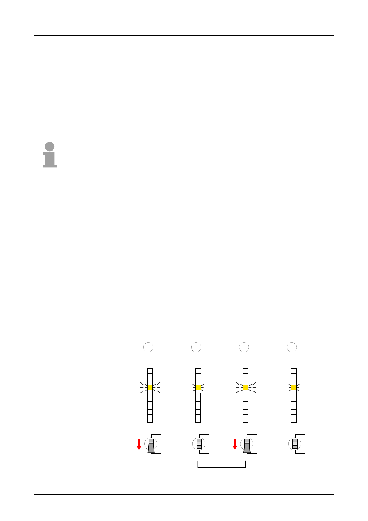
Chapter 4 Deployment CPU 31x Manual VIPA System 300V
Overall Reset
Outline
Overall reset by
means of the
function selector
During the overall reset the entire user memory (RAM) is erased. Data
located in the memory card is not affected.
You have 2 options to initiate an overall reset:
• initiate the overall reset by means of the function selector switch
• initiate the overall reset by means of t he Siem ens SIMATIC manager
Note!
You should always issue an overall reset to your CPU before loading an
application program into your CPU to ensure that all blocks have been
cleared from the CPU.
Condition
The operating mode of the CPU is STOP. Place the function selector on
the CPU in position "STOP"
→ the STOP-LED is on.
Overall reset
• Place the function selector in the position MRES and hold it in this
position for app. 3 seconds.
→ The STOP-LED changes f rom blink ing t o
permanently on.
• Place the function selector in the posit ion STOP and switch it to MRES
and quickly back to STOP within a period of less t han 3 seconds.
→ The STOP-LED blinks (o verall r eset procedure).
• The overall reset has been completed when the STOP-LED is on
permanently.
→ The STOP-LED is on.
The following figure illust rates the above procedure:
1 2 3 4
PLC
PWR
RUN
STOP
SF
FRCE
MMC
DESL
RUN
3 Sec.
STOP
MRES
PLC
PWR
RUN
STOP
SF
FRCE
MMC
DESL
RUN
STOP
MRES
3 Sec.
PLC
PWR
RUN
STOP
SF
FRCE
MMC
DESL
RUN
STOP
MRES
PLC
PWR
RUN
STOP
SF
FRCE
MMC
DESL
RUN
STOP
MRES
4-20 HB130E - CPU - Rev. 11/50
Page 73

Manual VIPA System 300V Chapter 4 Deployment CPU 31x
Overall reset by
means of the
Siemens SIMATIC
manager
Automatic reload
Condition
The operating mode of t he CPU must be STOP.
You may place the CPU in STOP mode by the menu command
PLC > Operating mode.
Overall reset
You may request the overall reset by means of the menu command
Clean/Reset
.
PLC >
In the dialog window you may place your CPU in STOP mode and start t he
overall reset if this has not been done as yet.
The STOP-LED blinks during the overall reset procedure.
When the STOP-LED is on permanently the overall reset procedure has
been completed.
At this point the CPU attempts to reload the parameters and the program
from the memory card.
→ The MMC-LED blinks.
When the reload has been completed, the LED is extinguished. The
operating mode of the CPU will be STOP or RUN, depending on the
position of the function select or
Reset to factory
setting
The following approach deletes the internal RAM of the CPU completely
and sets it back to the delivery state.
Please regard that the MPI address is also set back to default 2!
• Push down the reset lever for app. 30 seconds. T he ST-LED blink s.
After a few seconds the LED turns t o static light. Count the number
of static light phases because now the LED switches between static
light and blinking.
• After the 6
th
static light you release the reset lever and push it down
again shortly. Now the g reen RUN-LED is on once. T his means t hat
the RAM is totally deleted.
• Turn the power supply off and on again.
HB130E - CPU - Rev. 11/50 4-21
Page 74
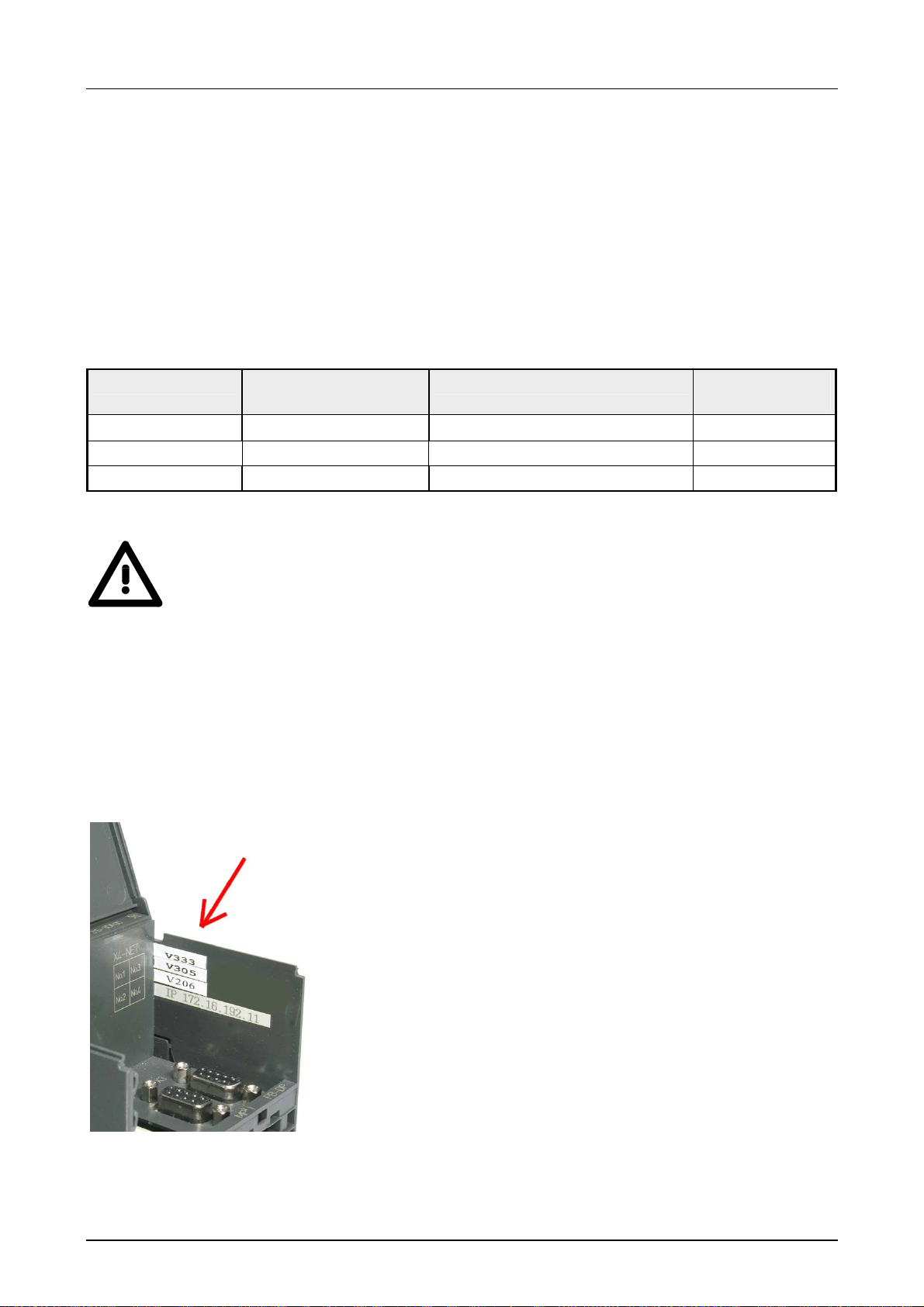
Chapter 4 Deployment CPU 31x Manual VIPA System 300V
r
Firmware update
Outline
At all CPUs of the System 300V you may execute a firmware update via
MMC starting with firmware version 3.3.0.
The latest 2 firmware versions are to find in the service area at
www.vipa.de.
By means of reserved file names in the CPU 31x you may transfer the
firmware updates per MMC for the following components:
Component Possible with
CPU version
CPU V. 3.3.3
Profibus master V. 3.0.5 Bb000089.version dpm00.bin
File name at server New file name
at MMC
order no.
_release.version
firmware.bin
*)
CP V. 2.0.6 Bb000125.version Bb000125.rtb
*)
When deploying the CPU firmware version V 3.3.3, the fil e name of the firmware update has to be dpm.bin!
Attention!
When installing a new firmware you have to be extremely careful. Under
certain circumstances you m ay destroy the CPU, f or example if the voltage
supply is interrupted during transfer or if the fir mware file is defective.
In this case, please call the VIPA-Hotline!
Please regard that the version of the update firmware has to be different
from the existing f irmware otherwise no update is executed.
Seek
firmware version
If you didn't execute a firmware update yet, there are labels beneath the
front flap at the right side showing the according firmware versions in
following sequence:
.
CPU firmware version
DP-Master firmware version
CP firmware version
Beneath the CP firmware version is a label with the
original IP address of the CP.
You may display the current fir mware version of your CPU
via the SIMATIC manager from Siem ens.
To display the firmware version, you go online with the
CPU via your PU res. PC and start the SIMATIC manage
from Siemens.
Via
PLC > Module status, regist er "General", the current
firmware version is evaluated and displayed.
4-22 HB130E - CPU - Rev. 11/50
Page 75

Manual VIPA System 300V Chapter 4 Deployment CPU 31x
Load firmware and
transfer it to MMC
with reserved
name
Transfer firmware
from MMC into
CPU
• Go to www.vipa.de/support/firmware
• Navigate to System 300V. Here the according firmware can be found.
• Download the firmware file. The according struct ure of the file name can
be found in the table above for renam ing.
• Rename the file and transf er this file onto a MMC.
• Get the RUN-STOP lever of your CPU in position STOP.
• Turn off t he voltage supply.
• Plug the MMC with the fir mware into the CPU. Please take care of the
correct plug-in direction of the MMC.
• Turn on the voltage supply.
• After a short boot-up time, the alternate blinking of the LEDs SF and
FRCE shows that the firmware file has been found on the MMC.
• You start the transf er of the f irmware as soon as you tip the RUN/ST OP
lever downwards to MRES within 10s. The CPU shows the transfer via a
LED blink line.
• During the update process, the LEDs SF, FRCE and MMC are
alternately blinking. This may last several m inut es.
• The update is successful finished when all CPU-LEDs are on. I f t hey are
blinking fast, an error occurred.
Note!
Starting with the WinNCS version 3.1.1 you may update the firmware of the
CP online via the parameterization window. This function is supported by
starting with CP firmware version 2.1.2.
For more detailed information see chapter "Deployment CPU 31x under
TCP/IP".
HB130E - CPU - Rev. 11/50 4-23
Page 76
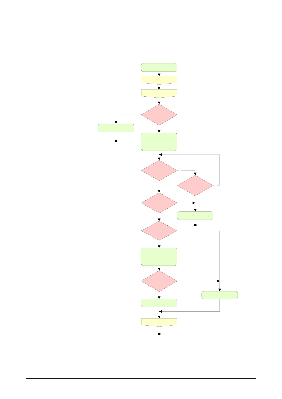
Chapter 4 Deployment CPU 31x Manual VIPA System 300V
Flowchart for
firmware update
The following flowchart illustrat e s t he CPU behavior at firmware update:
Power Off
Plug-in MMC
Power On
Switch=Stop?
n
CPU goes in RUN
blinking alternately
y
LED
SF and FRCE are
Switch=MR?
n
y
Update/Config
file(s) on
MMC?
y
File(s) OK?
Product name. .
y
FW Update/Config.
SF, FRCE, MMC are
blinking alternately
(ready) with
error?
n
All LEDs are on
10 seconds
passed?
n
CPU goes in STOP
n
y
y
n
All LEDs are blinking
Power Off
4-24 HB130E - CPU - Rev. 11/50
Page 77
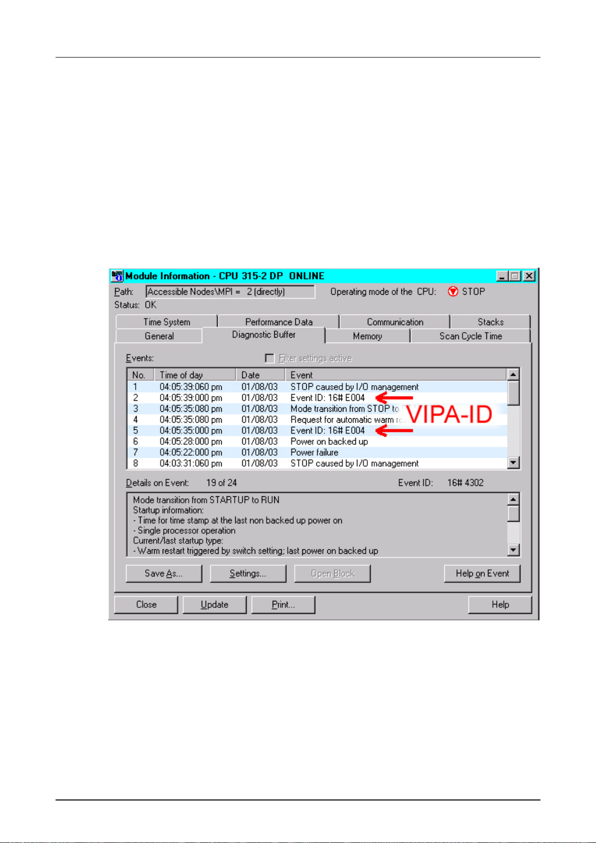
Manual VIPA System 300V Chapter 4 Deployment CPU 31x
VIPA specific diagnostic entries
Entries in the
diagnostic buffer
Monitoring the
diagnostic entries
You may read the diagnostic buff er of the CPU via the Siemens SIMATIC
Manager. Besides of the standard entr ies in the diagnostic buffer , the VIPA
CPUs support some additional specific entries in form of event-IDs.
To monitor the diagnostic entries you choose the option
Information
Buffer" you reach the diag nostic window:
in the Siemens SIMATIC Manager. Via the register "Diagnostic
PLC > Module
The diagnosis is independent from the operating mode of the CPU. You
may store a max. of 100 diagnostic entr ies in t he CPU.
The following page shows an overview of the VIPA specific Event-IDs.
HB130E - CPU - Rev. 11/50 4-25
Page 78

Chapter 4 Deployment CPU 31x Manual VIPA System 300V
Overview of the
Event-IDs
Event-ID Description
0xE003 Error at access to I/O devices
Zinfo1: I/O address
Zinfo2: Slot
0xE004 Multiple parameterization of a I/O address
Zinfo1: I/O address
Zinfo2: Slot
0xE005 Internal error - Please contact the VIPA-Hotline!
0xE006 Internal error - Please contact the VIPA-Hotline!
0xE007 Configured in-/output bytes do not fit into I/O area
0xE008 Internal error - Please contact the VIPA-Hotline!
0xE009 Error at access to standard back plane bus
0xE010 Not defined module group at backplane bus recognized
Zinfo2: Slot
Zinfo3: Type ID
0xE011 Master project engineering at Slave-CPU not possible or wrong slave config uration
0xE012 Error at parameterization
0xE013 Error at shift register access t o VBUS digital modules
0xE014 Error at Check_Sys
0xE015 Error at access to the master
Zinfo2: Slot of the m aster (32=page frame mast er )
0xE016 Maximum block size at master transfer exceeded
Zinfo1: I/O address
Zinfo2: Slot
0xE017 Error at access to integrated slave
0xE018 Error at mapping of the master I /O devices
0xE019 Error at standard back plane bus system recognition
0xE01A Error at recognition of the operating m ode (8 / 9 Bit)
0xE0CC Communicat ion error MPI / Serial
0xE100 MMC access error
0xE101 MMC error file system
0xE102 MMC error FAT
0xE104 MMC error at saving
0xE200 MMC writing finished (Copy Ram to Rom)
0xE210 MMC reading finished (reload after overall reset)
0xE300 Internal Flash writing ready (Copy RAM to ROM)
4-26 HB130E - CPU - Rev. 11/50
Page 79

Manual VIPA System 300V Chapter 4 Deployment CPU 31x
Using test functions for the control and monitoring of variables
Outline
Debug
> Monitor
For troubleshooting purposes and to display the stat us of certain variables
you can access certain test functions via the menu item
Siemens SIMATIC manager.
The status of the operands and t he VKE can be displayed by means of the
test function
You can modify and/or display the status of variables by means of the test
function
This test function displays the curr ent status and the VKE of the different
operands while the program is being executed.
It is also possible to enter corrections t o t he program.
Note!
When using the test function “Monitor” the PLC m ust be in RUN mode!
The processing of statuses can be interrupted by means of jump
commands or by timer and process-related alarms. At the breakpoint the
CPU stops collecting data for t he status display and instead of the req uired
data it only provides the PG with data containing the value 0.
For this reason, jumps or time and pr ocess alarms can result in the value
displayed during program execution remaining at 0 for the items below:
• the result of the log ical oper ation VKE
• Status / AKKU 1
• AKKU 2
• Condition byte
• absolute memory address SAZ. In this case SAZ is f ollowed by a "?".
The interruption of the processing of statuses does not change the
execution of the pr ogr am. It only shows that the data displayed is no longer
valid from the point on, where the interr upt occurred.
Debug > Monitor.
PLC > Monitor/Modify Variables.
Test of the
HB130E - CPU - Rev. 11/50 4-27
Page 80

Chapter 4 Deployment CPU 31x Manual VIPA System 300V
PLC >
Monitor/Modify
Variables
This test function returns the condition of a selected operand (inputs,
outputs, flags, data word, counters or timers) at the end of programexecution.
This information is obtained from the process image of the selected
operands. During the "processing check " or in operating mode STOP the
periphery is read directly from the inputs. Otherwise only the process
image of the selected operands is displayed.
Control of outputs
It is possible to check the wiring and proper operation of output-modules.
You can set outputs to any desired status with or without a control
program. The process image is not modified but outputs are no longer
inhibited.
Control of variables
The following variables may be modified:
I, Q, M, T, C and D.
The process image of binary and digital operands is modified
independently of the operating mode of the CPU 31x.
When the operating mode is RUN the program is executed with the
modified process variable. When the program continues they may,
however, be modified again without notification.
Process variables are controlled asynchronously to the execution sequence
of the program.
4-28 HB130E - CPU - Rev. 11/50
Page 81

Manual VIPA System 300V Chapter 5 Deployment CPU 31x with Profibus
Chapter 5 Deployment CPU 31x with Profibus
Overview
Content
Content of this chapter is the deployment of the CPU 31x with Profibus.
After a short overview the project engineering and parameterization of a
CPU 31x with integrated Profibus part VI PA is shown.
Here you will also get inf orm ation how the Prof ibus par t can be used as DP
master and DP slave.
The chapter is finished by hints for com missioning and start-up behavior.
Topic Page
Chapter 5
Overview..............................................................................................5-2
Project engineering CPU with integrated Profibus master....................5-3
Deployment as Profibus DP slave........................................................5-5
Profibus installation guidelines.............................................................5-7
Commissioning and Start-up behavior................................................5-10
Deployment CPU 31x with Profibus...............................5-1
HB130E - CPU - Rev. 11/50 5-1
Page 82

Chapter 5 Deployment CPU 31x with Profibus Manual VIPA System 300V
Overview
Profibus DP
CPU with
DP master
Deployment of the
DP-Master with
CPU
Profibus address
1 is reserved
DP slave operation
Profibus is an international standard applicable to an open and serial
fieldbus for building, manufacturing and process automation that can be
used to create a low (sensor-/actuator level) or medium (process level)
performance network of programmable logic controllers.
Profibus comprises an assortment of compatible versions. The following
details refer to Profibus DP.
Profibus DP is a special protocol intended mainly f or automation tasks in a
manufacturing environm ent. DP is very fast , of fer s Plug'n' Play facilities and
provides a cost-effective alternative to parallel cabling between PLC and
remote I/O. Profibus DP was designed for high-speed data communication
on the sensor-actuator level.
The data transfer referred to as "Data Exchange" is cyclical. During one
bus cycle, the master reads input values from t he slaves and writes output
information to the slave.
The Profibus DP master is to configure via the hardware config urator from
Siemens. Therefore you have to choose the Siemens-CPU 315-2AF03 in
the hardware configurator from Siemens.
The transmission of your project engineering into the CPU tak es place by
means of MPI. This is internally passing on your project data to the
Profibus master part. During the start-up the DP master automatically
mappes his data areas into the address area of the CPU. A configurat ion of
the CPU part is not required. As external storage medium the Prof ibus DP
master uses the MultiMediaCard (MMC) together with the CPU.
Via the Profibus DP master up to 125 Pr ofibus DP slaves may be coupled
to the CPU. The DP master comm unicates with the DP slaves and links up
its data areas with the address area of the CPU. There may be created
maximal 1024Byte Input and 1024Byte Output data.
At every POWER ON res. OVERALL RESET the CPU fetches the I/O
mapping data from t he master. At DP slave failure, the ER-LED is on and
the OB 86 is requested. If this is not available, the CPU switches to STOP
and BASP is set.
As soon as the BASP signal comes from t he CPU, the DP m aster is setting
the outputs of the connected peripher y to zero. The DP master remains in
the operating mode RUN independent f rom the CPU.
Please regard that the Prof ibus address 1 is reserved for the system. The
address 1 should not be used!
For the deployment in an super-ordinated master system you first have to
project your slave system as CPU 315-2DP (6ES7 315-2AF03- 0AB0/V1.2)
in Slave operation with configured in-/output areas. Afterwards you
configure your master system. Assign your slave system to your master
system. The assignment to your m aster systems happens for VIPA CPUs
31x with DP slave/master via Configured stations and for VIPA CPUs 31x
with DP slave via VIPA GSD file. Here drag the slave system from the
hardware catalog and drop it on the master system, onto the master
system, choose your slave system and connect it.
5-2 HB130E - CPU - Rev. 11/50
Page 83

Manual VIPA System 300V Chapter 5 Deployment CPU 31x with Profibus
Project engineering CPU with integrated Profibus master
Outline
Preconditions
For the project engineering of the Prof ibus DP master you have to use the
hardware manager from Siemens. Your Profibus projects are transferred
via MPI to the CPU 31xDPM by means of the "PLC" functions. The CPU
passes the data on to the Profibus DP mast er .
For the project engineering of the Profibus DP m aster in the CPU 31xDPM
the following preconditions have to be fulfilled:
• Hardware-Manager from Siemens has to be installed.
• With deployment of a DP Slave the appr opriate GSD is to be inst alled. I f
the slave system is a CPU 31x from VIPA no GSD is necessary.
• There is a transfer possibilit y between conf iguration tool and CPU 31x.
Note!
For the project engineering of the CPU and the Profibus DP master a
thorough knowledge of the STEP
®
7 manager and the hardware
configurator from Siemens is required!
Install Siemens
Hardware
configurator
Configure
DP master
®
The hardware configurator is a part of the STEP
7 projecting tool from
Siemens. It serves the project engineering. The modules that may be
configured here, are list ed in t he har dware catalog.
With deployment of a DP Slave the appropriate GSD is to be installed. If
the slave system is a CPU 31x from VIPA no GSD is necessary.
• Create a new project System 300.
• Add a profile rail from t he har dware cata log.
• In the hardware catalog the CPU with Profibus ma st er is listed as:
Simatic300/CPU-300/CPU315-2DP/6ES7 315-2AF03-0AB0
• Insert the CPU 315-2DP (6ES7 315-2AF03-0AB0).
• Type the Profibus address of your mast er ( e.g. 2).
• Click on DP, choose the operating mode "DP master" at object
properties and confirm your entry with OK.
• Click on "DP" with the right mouse button and choose "add master
system".
• Create a new Profibus subnet via NEW.
HB130E - CPU - Rev. 11/50 5-3
Page 84
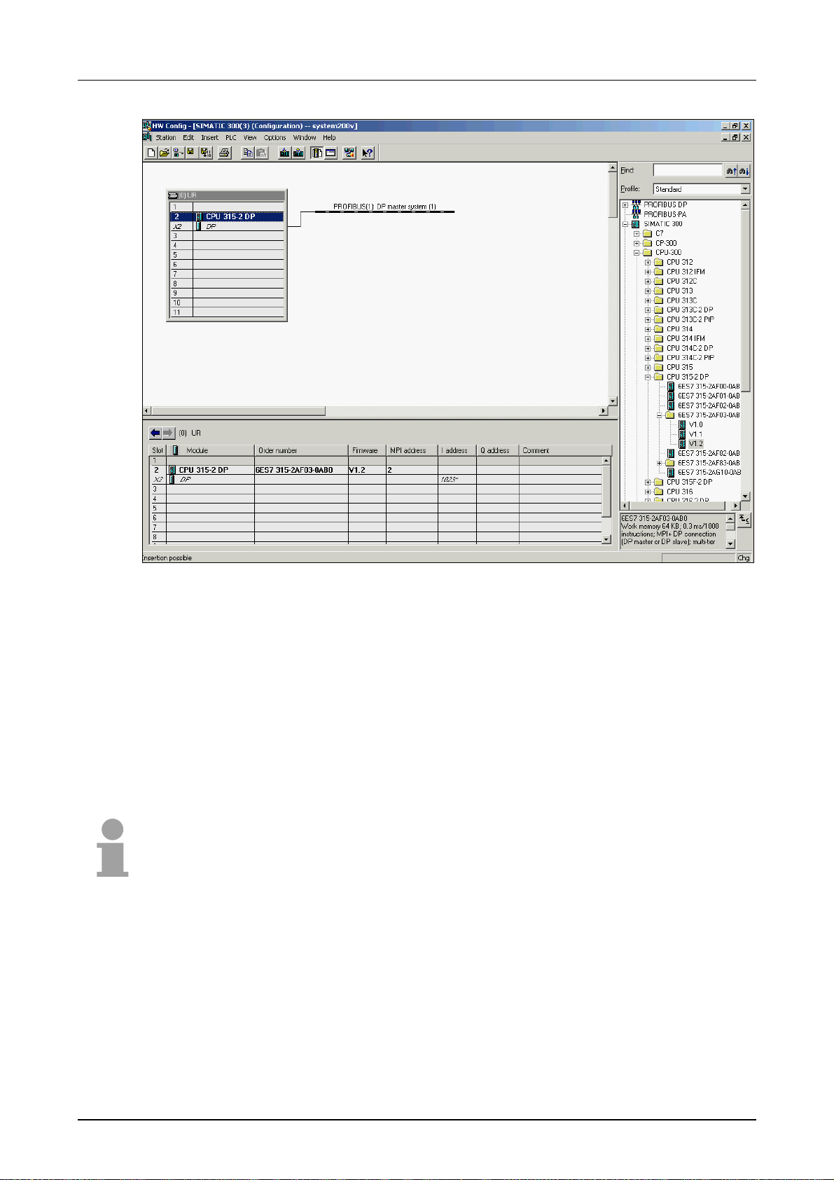
Chapter 5 Deployment CPU 31x with Profibus Manual VIPA System 300V
Slave operation
with firmware
3.4.0 or higher
Now the project engineer ing of your Prof ibus DP master is f inished. Please
link up now your DP slaves with periphery to your DP master.
• For the project engineering of Profibus DP slaves you search the
concerning Profibus DP slave in the hardwar e catalog and drag&drop it
in the subnet of your master.
• Assign a valid Profibus address to the DP slave.
• Link up the modules of your DP slave system in the plugged sequence
and add the addresses that should be used by the modules.
• If needed, parameterize the modules.
Note!
If you deploy an IM153 from Siemens with a VIPA CPU 31xDPM, please
use the "compatible" DP slave modules.
These are listed in the hardware catalog at PROFIBUS DP/
Additional Field Devices/Compatible Profibus DP-Slaves.
Starting with the CPU firmware 3.4. 0, you may deploy your DP master also
as DP slave. The approach is described on the f ollowing page at Project
engineering of the CPU with integrated Profibus slave".
Transfer project
Details about project transfer can be found at chapter "Deployment CPU
31x" at "Project transfer".
5-4 HB130E - CPU - Rev. 11/50
Page 85

Manual VIPA System 300V Chapter 5 Deployment CPU 31x with Profibus
Deployment as Profibus DP slave
Fast introduction
Project
engineering of
the slave section
The deployment of the Prof ibus section as "intelligent" DP slave happens
exclusively at master systems that may be configured in the Siemens
SIMATIC manager. The following steps are required:
• Start the Siemens SIMATIC manager and configure a CPU 315-2DP
with the operating mode DP slave.
• Connect to Profibus and configure the in-/output area for the slave
section.
• Save and compile your project.
• Configure another station as CPU 315-2DP with operating mode DP
master.
• Connect to Profibus and configure the in- /output ranges for the master
section
• Save and compile your project.
In the following these steps are more det ailed.
• Start the Siemens SIMATIC manager with a new project.
• Insert a SIMATIC 300 station and name it as "...DP slave"
• Open the hardware configurator and insert a profile rail from the
hardware catalog.
• Place the following Siemens CPU at slot 2:
CPU 315-2DP (6ES7 315-2AF03-0AB0 V1.2)
• Add your modules according to the real hardware assembly.
• Connect the CPU to Profibus, set a Prof ibus address >1 (preferably 3)
and switch the Profibus section via operating mode to "slave operation" .
• Via Configuration you define the in-/output address area of the slave
CPU that shall be assigned to the DP slave.
• Save, compile and transfer your project.
Slave section
Standard bus
Slot
1
2
X2
X1
3
Module
CPU 315-2
DP
MPI/DP
I/O devices
...
Object properties
Operating mode: DP slave
Connect: Profibus
Profibus address: > 1
Configuration:
Input area
Output area
HB130E - CPU - Rev. 11/50 5-5
Page 86
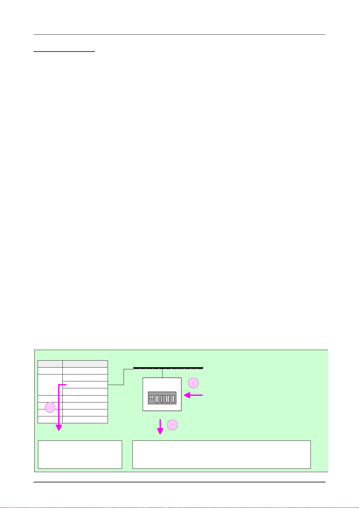
Chapter 5 Deployment CPU 31x with Profibus Manual VIPA System 300V
Project
engineering of the
master section
Assignment
Assignment VIPA
CPU 31x with DP
slave/master
Assignment VIPA
CPU 31x with DP
slave
• Insert another SIMATIC 300 station and name it as "...DP master".
• Open the hardware configurator and insert a profile rail from the
hardware catalog.
• Place the following Siemens CPU at slot 2:
CPU 315-2DP (6ES7 315-2AF03-0AB0 V1.2)
• Add your modules according to the real hardware assembly.
• Connect the CPU to Profibus, set a Prof ibus address >1 (preferably 2)
and switch the Profibus section via operating mode to "master
operation".
Dependent on the used VIPA CPU 31x of the slave part the assignment
happens either via Configured stations or by installing the VIPA GSD file
VIPA802F.gsd.
• Connect your slave system to the master system by dragging the " CPU
31x" from the hardware catalog at configured stations onto the master
system and select your slave system.
• In the service area of www.vipa.de the GSD file VIPA802F.gsd will be
found. Install this GSD at your har dware catalog.
• Connect your slave system to the master system by dragging the " CPU
31xDP" of the hardware catalog from Additional field devices > I/O >
VIPA_System_300V onto the master system.
Connection
• Open the Configuration at Object proper ties of your slave system.
• Via double click to the according configuration line you connect the
according input address area on the master CPU to the slave output
data and the output address area to the slave input data. Data
consistency can only be guaranteed for one unit! The choice "Data
consistency by length" is not supported.
• Save and compile your project.
Master section
Standard bus
Slot
1
2
X2
X1
3
1
Object pr op erties
Operating mode: DP master
Connect : P r ofibus
Profibus address: > 1
Module
CPU 315-2
DP
MPI/DP
I/O devices
...
DP master system
CPU with DP slave/master:
S7-300
3
Object properties
Configuration:
Input area slave CPU = Output area master-CPU
Output area slave CPU = Input area Master-CPU
2
Hardware catalog: CPU 31x from
Configured stations
CPU with DP slave:
Hardware catalog: CPU 31x DP from
Additional field devi ces > I/O > System300V
(VIPA802F.gsd)
5-6 HB130E - CPU - Rev. 11/50
Page 87

Manual VIPA System 300V Chapter 5 Deployment CPU 31x with Profibus
Profibus installation guidelines
Profibus in
general
• A Profibus DP network may only be built up in linear struct ur e.
• Profibus DP consists of minimum one segment with at least one master
and one slave.
• A master has always be deployed together with a CPU.
• Profibus supports max. 126 participants.
• Per segment a max. of 32 part icipant s is per m it t ed.
• The max. segment length depends on t he baud r at e:
9.6 ... 187.5kBaud → 1000m
500kBaud → 400m
1.5MBaud → 200m
3 ... 12MBaud → 100m
• Max. 10 segments may be built up. The segments are connected via
repeaters. Every repeater counts for one par ticipant.
• All participants are communicat ing with the same baudrate. The slaves
adjust themselves automatically on the baudrate.
• The bus has to be terminated at both ends.
• Master and slaves are free combinable.
Transfer medium
As transfer medium Profibus uses an isolated twisted-pair cable based
upon the RS485 interface.
The RS485 interface is working with voltag e differences. Though it is less
irritable from influences than a voltage or a cur rent interface. You ar e able
to configure the network as well linear as in a tree structure. Your VIPA
CPU 31x includes a 9pin slot where you connect the Profibus coupler into
the Profibus network as a slave.
Max. 32 participants per segment are permitted. The segments are
connected via repeaters. The maximum seg ment length depends on the
transfer rate.
Profibus DP uses a transfer rate between 9.6kBaud and 12MBaud, the
slaves are following automatically. All participants are communicating with
the same baudrate.
The bus structure of RS485 allows an easy connection res. disconnection
of stations as well as starting the system step by step. Later expansions
don’t have any influence on stations that are already integrated. The
system realizes automatically if one par tner had a f ail down or is new in the
network.
HB130E - CPU - Rev. 11/50 5-7
Page 88
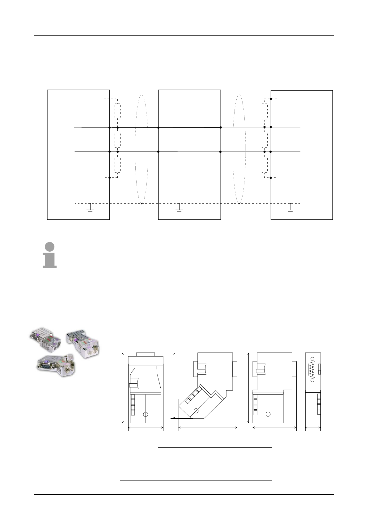
Chapter 5 Deployment CPU 31x with Profibus Manual VIPA System 300V
Bus connection
Master
RxD/TxD-P(B)
RxD/TxD-N(A)
Shield
The following picture illustrates the terminating resist ors of the respective
start and end station.
Slave
6
P5V P5V
330 330
3
220 220
8
330 330
5
M5V M5V
3
8
RxD/TxD-P(B)
RxD/TxD-N(A)
Shield
3
8
Slave
6
RxD/TxD-P(B)
3
RxD/TxD-N(A)
8
5
Shield
"EasyConn" Bus
connector
Note!
The Profibus line has to be term inated with its ripple resistor. Please make
sure to terminate the last participants on the bus at both end by activating
the terminating resistor .
In systems with more than two stations all partners are wired in parallel.
For that purpose, the bus cable must be feed-through uninterrupted.
Via the order number VIPA 972-0DP10 you may order the bus connector
"EasyConn". This is a bus connector with switchable terminating resistor
and integrated bus diagnostic.
0°
A
A
45°
90°
A
B
B
B
C
0° 45° 90°
A 64 61 66
B 34 53 40
C 15,8 15,8 15,8
all in mm
5-8 HB130E - CPU - Rev. 11/50
Page 89
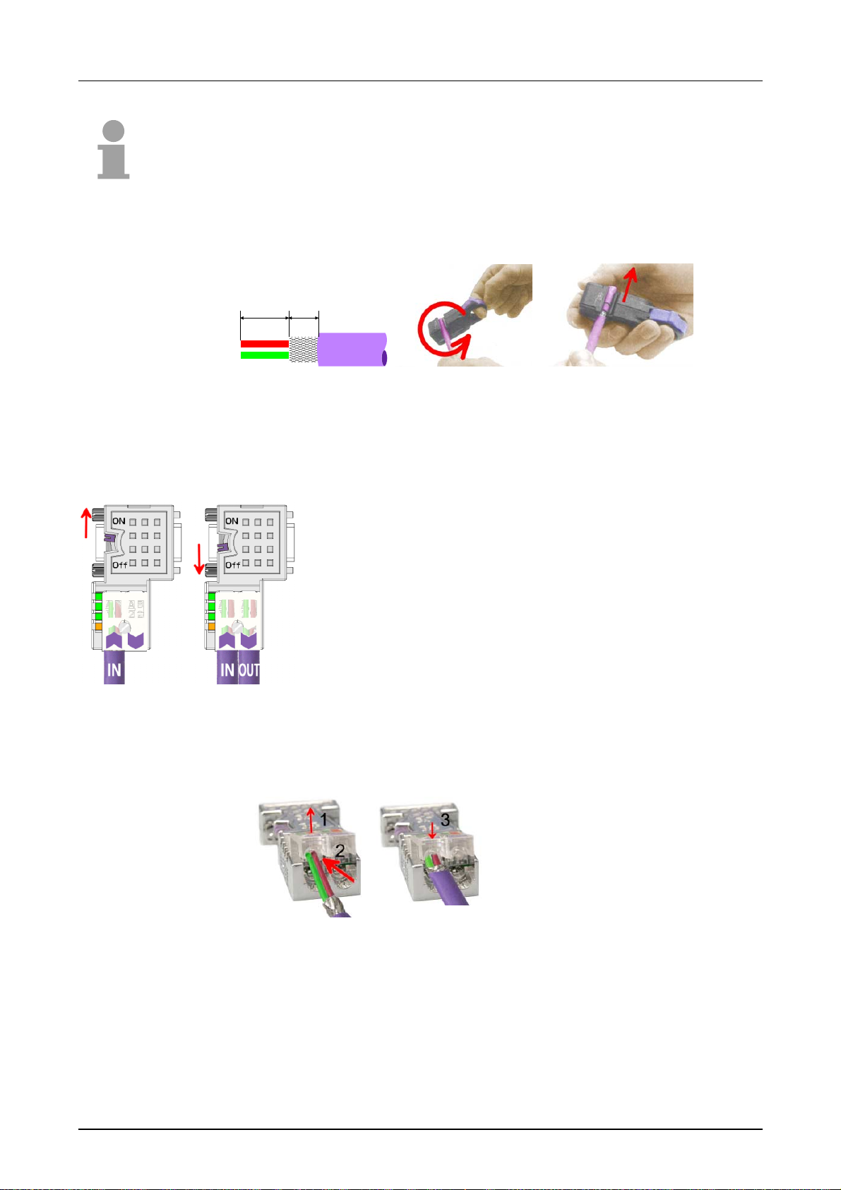
Manual VIPA System 300V Chapter 5 Deployment CPU 31x with Profibus
Note!
To connect this plug, please use the standard Profibus cable type A
(EN50170). Starting with release 5 you also can use highly flexible bus
cable: Lapp Kabel order no.: 2170222, 2170822, 2170322.
Under the order no. 905-6AA00 VIPA offers the "EasyStrip" de-isolating
tool, that makes the connection of the EasyConn much easier.
11 6
Dimensions in mm
Termination with
"EasyConn"
The "EasyConn" bus connector is provided with a switch that is used to
activate a terminating resistor.
Attention!
The terminating resistor is only effective, if the connector
is installed at a slave and the slave is connected to a
power supply.
Note!
A complete description of installation and deployment of
the terminating resistors is delivered with the connector .
Assembly
• Loosen the screw.
• Lift contact-cover.
• Insert both wires into the ducts provided
(watch for the correct line color as below!)
• Please take care not to cause a short
circuit between screen and data lines!
• Close the contact cover.
• Tighten screw
(max. tightening torque 4Nm).
Please note:
The green line must be connected to A, the red line to B!
HB130E - CPU - Rev. 11/50 5-9
Page 90

Chapter 5 Deployment CPU 31x with Profibus Manual VIPA System 300V
Commissioning and Start-up behavior
Start-up on
delivery
Online with bus
parameter without
slave project
Slave
configuration
CPU state controls
DP master
Master behavior at
CPU RUN
Master behavior at
CPU RUN
In delivery the CPU is overall reset . T he Profibus part is deactivated and its
LEDs are off after Power ON.
The DP master can be served with bus parameters by means of a
hardware configuration. As soon as these are transferred the DP master
goes online with his bus parameter. This is shown by the RUN LED. Now
the DP master can be contacted via Profibus by means of his Profibus
address. In this state the CPU can be accessed via Profibus to get
configuration and DP slave project.
If the master has received valid configuration data, he switches to Data
Exchange with the DP Slaves. This is indicated by the DE-LED.
After Power ON respectively a receipt of a new hardware configur ation the
configuration data and bus parameter were transferred to the DP mast er.
The DP master does not have any operation switch. His state is controlled
by the RUN/STOP state of the CPU.
Dependent on the CPU state the following behavior is shown by the DP
master:
• The global control command "Operate" is sent to the slaves by the
master. Here the DE-LED is ON.
• Every connected DP slave is cyclically attended with an output telegram
containing recent output data.
• The input data of the DP slaves were cyclically transferred to the input
area of the CPU.
• The global control command "Clear" is sent to the slaves by the master.
Here the DE-LED is blinking.
• DP slaves with fail safe mode were provided with output telegram length
"0".
• DP slaves without fail safe mode were provided with the whole output
telegram but with output data = 0.
• The input data of the DP slaves were furt her cyclically transferred t o the
input area of the CPU.
5-10 HB130E - CPU - Rev. 11/50
Page 91

Manual VIPA System 300V Chapter 6 Deployment CPU 31x w ith TCP/IP
Chapter 6 Deployment CPU 31x with TCP/IP
Outline
Content
The following chapter describes the deployment of the CPU 31xNET and
the communication with TCP/IP.
Topic Page
Chapter 6
Principles..............................................................................................6-2
Protocols..............................................................................................6-4
Network planning .................................................................................6-8
IP address..........................................................................................6-10
Project Engineering of the CPU 31xNET............................................6-11
PG/OP communication.......................................................................6-24
Firmware update and reboot .............................................................. 6-27
Access control....................................................................................6-30
Activate clock master .........................................................................6-31
IP parameters.....................................................................................6-33
Activate IPC .......................................................................................6-34
Start-up behavior................................................................................6-35
System properties of the CPU 31xNET..............................................6-36
Communication to other systems.......................................................6-37
Test program for TCP/IP connections................................................6-40
Sample communication TCPTest - CPU 31xNET...............................6-47
Sample communication CPU 31xNET - CPU 31xNET........................6-57
Support for error search.....................................................................6-67
Deployment CPU 31x with TCP/IP..................................6-1
HB130E - CPU - Rev. 11/50 6-1
Page 92

Chapter 6 Deployment CPU 31x with TCP/IP Manual VIPA System 300V
Principles
Network (LAN)
Twisted Pair
A network res. LAN (Local Area Net work) provides a link between diff erent
stations that enables them to communicat e with each other.
Network stations can consist of PCs, I PCs, TCP/IP adapters, etc.
Network stations are separated by a minimum distance and connected by
means of a network cable. The combination of network stations and the
network cable represent a complete segment .
All the segments of an network form the Ethernet (physics of a net work ) .
In the early days of net working the Triaxial- (yellow cable) or thin Ethernet
cable (Cheapernet) was used as communication medium. This has been
superseded by the twisted pair network cable due to its immunity to
interference. The CPU 31xNET m odule has a twisted-pair connector.
The twisted pair cable consists of 4 cores that are twisted toget her in pairs.
Due to these twists, this system provides an increased level of immunity to
electrical interference.
Where the coaxial Ethernet networks are based on a bus topology the
twisted pair network is based on a point-to-point scheme.
The network that may be established by means of this cable has a star
topology. Every station is connected to the hub/switch by means of a
separate cable. The hub/switch provides the interf ace t o t he Et hernet.
Hub
Switch
The hub is the central element that is r equired to implement a twisted pair
Ethernet network.
It is the job of the hub to regenerate and to amplify the signals in both
directions. At the same time it must have the facility to detect and process
segment wide collisions and to relay this information. The hub is not
accessible by means of a separate network address since it is not visible to
the stations on the network.
A hub has provisions to interface with thin- and/or thick-Ethernet or to
another hub res. switch.
A switch also is a central element for realizing Ethernet on Twisted Pair.
Several stations res. hubs are connected via a switch. Afterwards they are
able to communicate with each other via the switch without interf ering the
network. An intelligent hardware analyzes the incoming teleg rams of every
port of the switch and passes them collision free on to the destination
stations of the switch. A switch optimizes the bandwidth in every connected
segment of a network. Switches enable exclusive connections between the
segments of a network chang ing at request.
6-2 HB130E - CPU - Rev. 11/50
Page 93
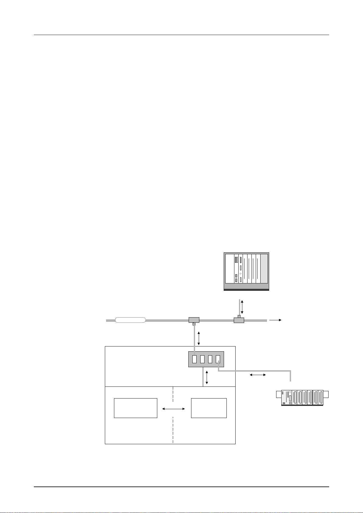
Manual VIPA System 300V Chapter 6 Deployment CPU 31x w ith TCP/IP
Access Control
Communication
Ethernet supports the principle of random bus accesses: every station on
the network accesses the bus independently as and when required. These
accesses are coordinated by a CSMA/CD (Carrier Sense Multiple
Access/Collision Detection) scheme: every station "listens" on the bus
cable and receives communication messages that are addressed to it .
Stations only initiate a transmission when the line is unoccupied. In the
event that to participants should start transmitting simultaneously, they will
detect this and stop transmitting, to restart after a random delay time has
expired.
The internal CP of the CPU 31xNET is dir ectly connected to the CPU 31x
by means of a Dual-Port-RAM. The Dual- Port-RAM is divided into 4 equal
segments called page fram es.
These 4 page frames are available at t he CPU as Standard-CP-Interface.
Data is exchanged by means of standard handler blocks (SEND and
RECEIVE).
The communication under TCP/IP is controlled by means of connections.
These are defined by means of the VIPA configuration tool WinNCS and
transferred into the CPU via the Twisted-Pair connector.
For details on the configuration, please refer to the WinNCS manual
(HB91)
VIPA Rack-135U
VIPA Rack-135U
Ethernet
Ethernet
CPU 31x NET
Anwender-
Application
programm
program
(SEND, RECEIVE)
(SEND, RECEIVE)
4port Switch
Daten
Daten
HTBs
HTBs
Frames
Frames
Frames
CPCPU
CPCPU
Verbindungen
Connections
parametriert
configured
mit WinNCS
with WinNCS
CP 143 H1 / TCP/IP
CP 143 H1 / TCP/IP
Frames
Frames
Frames
Frames
additional interfaces
System 200V
System 200V
CPU 21x NET
CPU 21x NET
HB130E - CPU - Rev. 11/50 6-3
Page 94

Chapter 6 Deployment CPU 31x with TCP/IP Manual VIPA System 300V
Protocols
Outline
TCP/IP
Protocols define a set of instructions or standar ds that enable computer to
establish communication connections and exchange information as error
free as possible.
A commonly established protocol for the standardization of the complete
computer communication is the so called ISO/OSI layer model, a model
based upon seven layers with rules for the usage of hardware and
software.
More detailed information about the ISO/OSI layer model is to find in the
chapter "Principles".
The CPU 31xNET from VIPA uses the following protocols that are
described in the following:
• TCP/IP
• UDP
• RFC1006
TCP/IP protocols are available on all m ajor systems. At the bot tom end t his
applies to simple PCs, through to the typical mini-computer up to
mainframes (TCP/IP implementations also exist for IBM-systems) and
special processors like vector processors and parallel comput er s.
For the wide spread of internet accesses and connections, T CP/IP is often
used to assemble heterogeneous system pools.
TCP/IP, standing f or Transmission Control Protocol and Internet Protocol,
collects a various range of protocols and f unct ions.
TCP and IP are only two of the protocols required for the assembly of a
complete architecture. The application layer provides programs like "FTP"
and "Telnet" for t he PC.
The application layer of the Ethernet portion of the CPU 31xNET is defined
with the user application using the standard handling block s .
These user applications use the transport layer with the protocols TCP and
UDP for the data transfer which themselves communicate via the IP
protocol with the internet layer.
6-4 HB130E - CPU - Rev. 11/50
Page 95

Manual VIPA System 300V Chapter 6 Deployment CPU 31x w ith TCP/IP
IP
The internet protocol covers the network layer (Layer 3) of the ISO/OSI
layer model.
The purpose of IP is to send data pack ages f r om on PC t o another passing
several other PCs. These data packages are referred to as datagrams.
The IP doesn't guarantee the correct sequence of the datagrams nor the
delivery at the receiver.
For the unambiguous identification between sender and receiver 32Bit
addresses (IP addresses) are used that are normally written as four octets
(exactly 8Bit), e.g. 172.16.192. 11.
These internet addresses are defined and assigned worldwide from the
DDN network (Defense Department Network), thus every user may
communicate with all other TCP/IP users.
One part of the address specifies the network, the rest serves the
identification of the participants inside the network. The boarder between
the network and the host port ion is variable and depends on the size of the
network.
To save IP addresses, so called g ateways are used that have one official
IP address and cover the network. Then the network can use any IP
address.
TCP
UDP
The TCP (Transmission Control Protocol) bases directly on the IP and thus
covers the transport layer (layer 4) of the OSI layer model. TCP is a
connection orientated end-to-end protocol and serves the logic connection
between two partners.
TCP guarantees the correct sequence and reliability of the data transfer.
Therefore you need a relative large pr otocol overhead that slows down the
transfer speed.
Every datagram gets a header of at least 20 octets. This header also
contains a sequence number identifying the series. This has the
consequence that the single datagrams may reach the destination on
different ways through the network.
The UDP (User Datagram Protocol) is a connection f ree transpor t protocol.
It has been defined in the RFC768 (Request for Comment). Compared to
TCP, it has much fewer characteristics.
The addressing happens via port numbers.
UDP is a fast unsafe protocol for it doesn't care about missing data
packages nor about their sequence.
HB130E - CPU - Rev. 11/50 6-5
Page 96

Chapter 6 Deployment CPU 31x with TCP/IP Manual VIPA System 300V
RFC1006
Properties
The TCP transport service works stream orientated. This m eans that data
packages assembled by the user not necessarily have to receive the
partner in the sam e packaging. Packages may reach the partner and the
package borders are not recog nized.
However, most applications require a message or ient ation.
This means that you need another protocol above TCP. This purpose is
defined in the protocol RFC1006. The protocol definition describes the
function of an I SO t ransport inter f ace (ISO 8072) basing upon the t ranspor t
interface TCP (RFC793).
The basic protocol of RFC1006 is nearly identical to TP0 (Transport
Protocol, Class 0) in ISO 8073.
For RFC1006 is run as pr otocol for TCP, the decoding takes place in the
data section of the TCP package.
• The project engineering happens via VIPA WinNCS V 3.02 or higher .
• With RFC1006 only SEND and RECEIVE commands are permissible.
• If the CP should act as an active partner, a SEND order must be
projected, should it act as an passive partner you have to project a
RECEIVE order.
• For every SEND order, the CP automatically creates a RECEIVE order
and vice versa. The assignment of order numbers for the automat ically
created orders is following this rules:
- SEND commands may only hav e odd order numbers. The automa tically generated RECEIV E order gets the next high er even order
number. (Example: SEND, ANR:5 → RECEI VE, ANR:6)
- RECEIVE commands may only have ev en order numbers. The auto matically created SEND order gets the next lower odd
order number. (Example: RECEIVE, ANR:2 → SEND, ANR:1)
• Automatically created orders are not monit or ed in WinNCS.
• For the addressing TSAPs are used instead of ports besides of the IP
address.
• The TSAP definition differentiates between small letters and capit als.
• The maximum length of TSAPs is 8 signs. The length has to be preset
in WinNCS.
• Independently from the used protocol t he standar d SEND and RECEIVE
commands of the PLC are necessary for data transfer.
6-6 HB130E - CPU - Rev. 11/50
Page 97
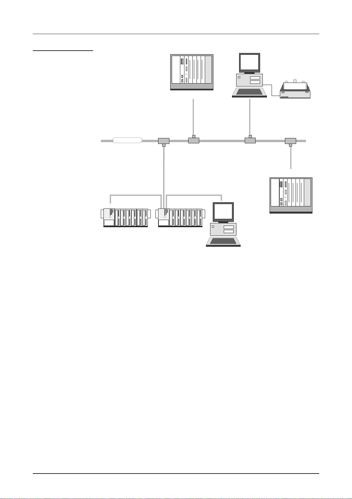
Manual VIPA System 300V Chapter 6 Deployment CPU 31x w ith TCP/IP
Example of a
TCP/IP application
System 300V
TCP/IP
VIPA Rack-135U
CP 143 TCP/IP
System 300V
Visualization and
shop floor data collection
via OPC-Server
VIPA Rack-135U
CP 143 TCP/IP
CPU31xNET
CPU31xNET
HB130E - CPU - Rev. 11/50 6-7
Page 98

Chapter 6 Deployment CPU 31x with TCP/IP Manual VIPA System 300V
Network planning
General
Standards and
guidelines
ANSI American National St andards Institute
The main property of the bus structure is that it consists of a single physical
connection. The physical communication medium consists of :
• one or more electrical cables (twisted pair cable)
• coaxial cable (Triaxial cable)
• fiber optic cables
The applicable rules and reg ulations must be satisfied in or der to establish
reliable communications between the differ ent stations.
These agreements define the form of the data protocol, the method of
access to the bus and other principles that are important for reliable
communications.
The VIPA CPU 31xNET was developed in accordance with the standards
defined by ISO.
International and national committees have def ined the following standards
and guidelines for networking t echnologies:
The ANSI X3T9.5 standard cur rently defines the provisions for high speed
LAN’s (100 MB/s) based on fiber optic technology.
(FDDI) Fiber Distributed Data Interface.
CCITT Committee Consultative Internationale de Telephone et Telegraph.
Amongst others, this advisory committ ee has pr oduced t he pr ovisions for
the connection of industrial networks (MAP) to office networks (TOP) on
Wide Area network s (WAN).
ECMA European Computer Manufact ur er s Associat ion.
Has produced various MAP and TOP standards.
EIA Electrical Industries Association (USA)
This committee has issued standard def initions like RS-232 (V.24) and
RS-511.
IEC International Electrotechnical Commission.
Defines certain special standards, e.g . for the Field bus.
ISO In t ernational Organization for Standardization.
This association of national standards organizations developed the OSImodel (ISO/TC97/SC16). It provides the framework f or the standardization
of data communications. ISO standards are included in different nat ional
standards like for example UL and DIN.
IEEE Institute of Electrical and Electr onic Engineers (USA).
The project-group 802 deter mines LAN-standards for transf er rates of 1 to
20MB/s. IEEE standards often for m the basis for ISO-standards, e.g. IEEE
802.3 = ISO 8802.3.
6-8 HB130E - CPU - Rev. 11/50
Page 99
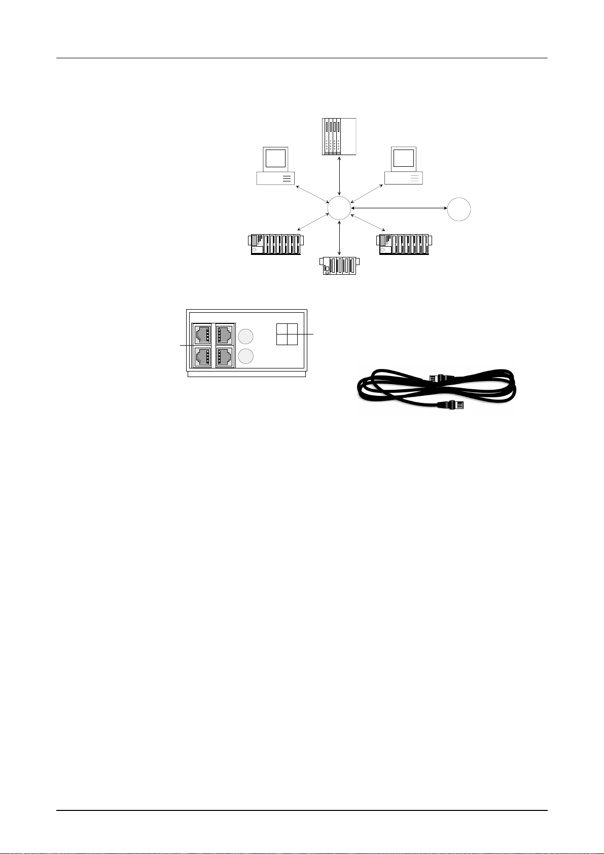
Manual VIPA System 300V Chapter 6 Deployment CPU 31x w ith TCP/IP
Overview over the
components
A twisted pair network can only be constructed with a star topology.
Hub/
Switch
Hub/
Switch
CPU 31xNET Twisted pair cable
X4
1
X4-NET
No.1 No.3
No.2 No.4
At twisted pair cable has four conductors
twisted together in pairs. The different
2
conductors have a diameter of 0.4 to
0.6mm.
Restrictions
Analyzing the
requirements
[1] 4port Switch
[2] Switch assignment
There are a few restrictions and rules that must be taken into account
using twisted pair:
• Maximum number of hub elements per segment 2
• Maximum length of one segment 100m
• What is the size of the area that must be served by the network?
• How many network segments provide the best solution for t he physical
(space, interference relat ed) condit ions encount er ed on site?
• How many network stations (SPS, IPC, PC, transceiver, bridges if
required) must be connected to the cable?
• What is the distance between the different stations on the network?
• What is the expected “growth rate” and the expected number of
connections that must be catered for by the system?
• What data amount has to be handled (band width, accesses/sec.)?
Drawing a
network diagram
Draw a diagram of the network. Identify every hardware item (i.e. station
cable, hub, switch). Observe the applicable rules and restrictions.
Measure the distance between all components to ensure that the maximum
length is not exceeded.
HB130E - CPU - Rev. 11/50 6-9
Page 100

Chapter 6 Deployment CPU 31x with TCP/IP Manual VIPA System 300V
IP address
IP address
structure
Initial Address
The IP address is a 32Bit address that m ust be unique within the network.
The IP address consists of 4 numbers t hat are separated by a full stop.
The structure of an IP addr ess is as follows:
Range: 000.000.000.000 to 255.255.255. 255
The network administrator also defines IP addresses.
The broadcast address (transmit a m essage to all stations) is always:
255.255.255.255
Attention!
Certain IP addresses are restricted e. g. 000.000. 000.000 These addr esses
are reserved for special services!
When the CPU 31xNET is first turned on, the module has an predef ined
initial IP address.
This address is available from a label that has been att ached to the side of
the module res. in the protocol added to your CPU.
At the first commissioning , the CP por tion has the f ollowing default set tings
for IP address and subnet mask:
IP Address: 172.16. 192.11
Subnet Mask: 255.255.255. 0
Starting with W inNCS version V 3.12 you have the comfortable possibility
to search stations in the Ethernet, to import their project engineering an to
change their IP addresses without changing the I P cir c uit .
xxx.xxx.xxx.xxx
Attention!
Please regard! If you change t he I P Addr ess of the CP by using
6-10 HB130E - CPU - Rev. 11/50
[Change IP], the configuration inside the CP is cleared.
 Loading...