

VIPA CPU 21xCAN Series, CPU 21xDP Series, CPU 214, CPU 21x-2BT02 Series, CPU 214-2BT02 Series Manual
...Page 1

Manual
VIPA CPU 21x
Order No.: VIPA HB103E
Rev. 05/45
Page 2

Lerrzeichen
Page 3

Manual VIPA CPU 21x About this Manual
The information in this m anual is supplied without warranties. Inf ormat ion is
subject to change without notice.
© Copyright 2005 VIPA, Gesellschaft für Visualisierung und Prozess-
automatisierung mbH
Ohmstraße 4, D-91074 Herzogenaurach,
Tel.: +49 (91 32) 744 -0
Fax.: +49 (91 32) 744-144
EMail: [email protected]
http://www.vipa.de
Hotline: +49 (91 32) 744-114
All rights reserved
Disclaimer of
liability
Trademarks
The contents of this manual was carefully examined to ensure that it
conforms with the described hardware and software.
However, discrepancies can not be avoided. The specifications in this
manual are examined regularly and corrections will be included in
subsequent editions.
We gr atefully accept suggestions f or im pr ovement .
VIPA
is a registered trademark of VIPA Gesellschaft für
Visualisierung und Prozessautomatisierung mbH
STEP
is a registered trademark of Siemens AG.
Any other trademarks referred to in the text are the trademarks of the
respective owner and we acknowledge their registration.
Subject to change to cater for technical progress.
Page 4

About this Manual Manual VIPA CPU 21x
About this manual
This manual describes the operation of the CPU 21x in the System 200V from
VIPA. The text provides details on the hardware, the programming and the
functions integrated into the unit as well as Profibus and Ethernet applications.
Outline
Chapter 1: Principles
This introduction includes recommendat ions on the handling of the m odule
as well as information about applications and implementation for CPU
modules. You may also read details about the mode of operation of the
CPU 21x.
Chapter 2: Hardware description
Different versions of the CPU are available This chapter describes these
versions in detail.
Chapter 3: Deployment of the CPU 21x
This chapter describes the deployment of the CPU section together with
the peripheral modules of the System 200V that are installed on the same
bus rail.
Chapter 4: Deployment of the CPU 21x-2BT10 under TCP/IP
This chapter describes applications of the CPU 21x-2BT10 and the
communication of the CP using T CP/ IP.
The CP is parameterizable with NetPro from Siemens.
Chapter 5: Deployment of the CPU 21x-2BT02 under H1 / TCP/IP
This chapter describes applications of the CPU 21x-2BT02 and the H1
resp. TCP/IP communication procedure of the CP.
The CP is parameterizable with WinNCS.
Chapter 6: Deployment of the CPU 21xDPM
Content of this chapter is the deployment and project engineering of the
CPU 21xDPM with integrated Profibus-DP master. Besides t he description
of the DP master operating modes you will also find information about the
start-up behaviour and the commissioning.
Chapter 7: Deployment of the CPU 21xDP
Topic of this chapter is the CPU 21xDP (int elligent slave). You will find the
description of the deployment, configuration and parameter definition for
the CPU 21xDP under Profibus.
Chapter 8: Deployment of the CPU 21xCAN
Content of this chapter is the employment of the CPU 21xCAN under
CANopen. Here you’ll find all information required for the usage of the
integrated CAN master.
Subject to change to cater for technical progress.
Page 5

Manual VIPA CPU 21x About this Manual
Chapter 9: Deployment of the CPU 21xSER- 1
Content of this chapter is the deployment of the CPU 21xSER-1 with
RS232C/RS485 interface..
Chapter 10: Deployment of the CPU 21xSER-2
Content of this chapter is the deployment of the CPU 21x-2BS02 with two
RS232C interfaces.
Chapter 11: Integrated OBs, SFBs, SFCs
Here you find the description of the int egr ated VIPA-specific SFCs, like e.g.
the SFCs for the CP communication.
Chapter 12: Command list
This chapter lists all available commands of the CPU in alphabetical order.
Subject to change to cater for technical progress.
Page 6

About this Manual Manual VIPA CPU 21x
Subject to change to cater for technical progress.
Page 7

Manual VIPA CPU 21x Contents
Contents
User considerations................................................................................. 1
Safety information.................................................................................... 2
Chapter 1
Principles.........................................................................1-1
Safety information for users .................................................................1-2
Hints for the deployment of the MPI interface.......................................1-3
Hints for the Green Cable from VIPA...................................................1-4
Overview System 200V........................................................................1-5
Function security of the VIPA CPUs.....................................................1-6
General description of the System 200V..............................................1-7
Overview CPU 21x...............................................................................1-8
Hints for project engineering ................................................................1-9
Application fields................................................................................1-13
Features.............................................................................................1-14
Operating modes of a CPU................................................................1-15
CPU 21x programs.............................................................................1-16
CPU 21x operands.............................................................................1-16
Chapter 2 Hardware description .....................................................2-1
System overview..................................................................................2-2
Structure ............................................................................................2-11
Components.......................................................................................2-13
Block diagram....................................................................................2-22
Technical data....................................................................................2-23
Chapter 3 Deployment CPU 21x...................................................... 3-1
Assembly..............................................................................................3-2
Start-up behavior..................................................................................3-3
Address allocation................................................................................3-4
Project engineering..............................................................................3-6
Configuration of the CPU parameters ..................................................3-9
Project transfer...................................................................................3-11
Operating modes................................................................................3-14
Overall Reset .....................................................................................3-15
Firmware update................................................................................3-17
Using test functions for the control and monitoring of variables..........3-20
Chapter 4 Deployment of the CPU 21x-2BT10 with TCP/IP........... 4-1
Industrial Ethernet in automation..........................................................4-2
ISO/OSI reference model.....................................................................4-3
Principles..............................................................................................4-6
Protocols..............................................................................................4-7
IP address and subnet .......................................................................4-10
Network planning ...............................................................................4-12
Communication possibilities of the CP ...............................................4-15
Function overview.............................................................................. 4-18
Fast introduction.................................................................................4-19
Hardware configuration......................................................................4-23
Configure connections........................................................................4-26
SEND/RECEIVE with PLC program...................................................4-32
Project transfer...................................................................................4-37
NCM diagnostic – Help for error diagnostic........................................4-39
Coupling to other systems.................................................................. 4-42
Example communication CPU21x-2BT10...........................................4-45
HB103E - Rev. 05/45 i
Page 8

Contents Manual VIPA CPU 21x
Chapter 5 Deployment CPU 21x-2BT02 with H1 / TCP/IP ..............5-1
Principles..............................................................................................5-2
Network planning .................................................................................5-7
Ethernet and IP addresses...................................................................5-9
Project Engineering of the CPU 21x-2BT02.......................................5-11
Configuration example CPU 21x-2BT02.............................................5-24
Start-up behavior................................................................................5-35
System properties of the CPU 21x-2BT02..........................................5-36
Communication to other systems.......................................................5-38
Test program for TCP/IP connections................................................5-41
Chapter 6 Deployment of the CPU 21xDPM....................................6-1
Principles..............................................................................................6-2
Project engineering CPU with integrated Profibus-DP master..............6-5
Project transfer.....................................................................................6-9
DP master operating modes...............................................................6-12
Commissioning and Start-up behavior................................................6-13
Chapter 7 Deployment of the CPU 21xDP.......................................7-1
Principles..............................................................................................7-2
CPU 21xDP configuration.....................................................................7-7
DP slave parameters..........................................................................7-12
Diagnostic functions...........................................................................7-15
Internal status messages to CPU.......................................................7-18
Profibus Installation guidelines...........................................................7-20
Commissioning...................................................................................7-26
Example.............................................................................................7-28
Chapter 8 Deployment CPU 21xCAN...............................................8-1
Principles CAN-Bus..............................................................................8-2
Project engineering of the CPU 21xCAN..............................................8-4
Modes................................................................................................8-13
Process image of the CPU 21xCAN................................................... 8-14
CANopen - Messages........................................................................8-16
Object directory..................................................................................8-21
Chapter 9 Deployment CPU 21xSER-1............................................9-1
Fast introduction...................................................................................9-2
Protocols and procedures ....................................................................9-3
Deployment of the serial interface........................................................9-7
Principles of data transfer.....................................................................9-8
Parameterization................................................................................9-10
Communication..................................................................................9-14
Modbus slave function codes.............................................................9-20
Modbus – Example communication....................................................9-24
Chapter 10 Deployment CPU 21xSER-2..........................................10-1
Principles............................................................................................10-2
Protocols and Procedures..................................................................10-3
RS232C interface ............................................................................... 10-7
Communication..................................................................................10-8
Initialize interfaces..............................................................................10-9
Interface parameters........................................................................10-11
Interface communication..................................................................10-14
ii HB103E - Rev. 05/45
Page 9

Manual VIPA CPU 21x Contents
Chapter 11 Integrated OBs, SFBs, SFCs........................................ 11-1
Integrated OBs and SFBs ..................................................................11-3
Integrated standard SFCs..................................................................11-4
VIPA specific SFCs............................................................................11-6
Include VIPA library............................................................................11-7
SFC 216 SER_CFG...........................................................................11-8
SFC 217 SER_SND......................................................................... 11-10
SFC 218 SER_RCV......................................................................... 11-11
SFC 219 CAN_TLGR.......................................................................11-12
SFC 220 MMC_CR_F......................................................................11-15
SFC 221 MMC_RD_F......................................................................11-17
SFC 222 MMC_WR_F ..................................................................... 11-18
SFC 223 PWM.................................................................................11-19
SFC 224 HSC..................................................................................11-21
SFC 225 HF_PWM ..........................................................................11-23
SFC 227 - TD_PRM.........................................................................11-25
SFC 228 - RW_KACHEL..................................................................11-27
Page frame communication - Parameter.......................................... 11-29
Page frame communication - Parameter transfer.............................11-32
Page frame communication - Source res. destination definition.......11-33
Page frame communication - Indicator word ANZW ......................... 11-36
Page frame communication - Parameterization error PAFE.............11-43
SFC 230 - SEND.............................................................................. 11-44
SFC 231 - RECEIVE........................................................................ 11-45
SFC 232 - FETCH ............................................................................ 11-46
SFC 233 - CONTROL...................................................................... 11-47
SFC 234 - RESET............................................................................ 11-48
SFC 235 - SYNCHRON....................................................................11-49
SFC 236 - SEND_ALL......................................................................11-50
SFC 237 - RECEIVE_ALL................................................................11-51
SFC 238 - CTRL1 ............................................................................11-52
Chapter 12 Instruction list............................................................... 12-1
Alphabetical instruction list.................................................................12-2
Abbreviations .....................................................................................12-5
Registers............................................................................................12-7
Addressing examples.........................................................................12-8
Math instructions..............................................................................12-11
Block instructions............................................................................. 12-13
Program display and null instruction instructions..............................12-14
Edge-triggered instructions ..............................................................12-14
Load instructions.............................................................................. 12-15
Shift instructions...............................................................................12-18
Setting/resetting bit addresses.........................................................12-19
Jump instructions.............................................................................12-20
Transfer instructions.........................................................................12-22
Data type conversion instructions..................................................... 12-25
Comparison instructions................................................................... 12-26
Combination instructions (Bit)...........................................................12-27
Combination instructions (Word)......................................................12-33
Timer instructions.............................................................................12-33
Counter instructions......................................................................... 12-34
VIPA specific diagnostic entries .......................................................12-35
Appendix...............................................................................................A-1
Index....................................................................................................A-1
HB103E - Rev. 05/45 iii
Page 10

Contents Manual VIPA CPU 21x
iv HB103E - Rev. 05/45
Page 11

Manual VIPA CPU 21x User considerations
User considerations
Objective and
contents
Target audience
Structure of the
manual
Guide to the
document
Availability
Icons
Headings
This manual describes the CPU 21x as well as all the versions of the
product. It contains a description of the construction, project implementation and the application of the product .
The CPU 21x is compatible with all System 200V components of VIPA.
The manual is targeted at users who have a background in automation
technology and PLC-programming.
This manual consists of 12 chapters. Every chapter provides the
description of one specific topic.
This manual provides the following guides:
• An overall table of contents at the beg inning of the manual
• An overview of the topics for every chapter
• An index at the end of the manual.
The manual is available in:
• printed form on paper
• in electronic form as PDF-file (Adobe Acrobat Reader)
Important passages in the text are highlighted by following icons and
headings:
Danger!
Immediate or likely danger.
Personal injury is possible.
Attention!
Damages to property is likely if these warnings are not heeded.
Note!
Supplementary information and usef ul tips.
HB103E - Rev. 05/45 1
Page 12

Safety information Manual VIPA CPU 21x
Safety information
Application
specifications
Documentation
The CPU 21x is constructed and manufactured for
• all VIPA System 200V components
• communication and process control
• general control and automation tasks
• industrial applications
• operation within the environmental conditions specified in the technical
data
• installation into a cubicle
Danger!
This device is not certified for applications in
• explosive environments (EX-zone)
The manual must be available to all personnel in the
• project design department
• installation department
• commissioning
• operation
Disposal
The following conditions must be met bef ore usi ng or commi ssioning
the components described in this manual:
• Modification to the process control system should only be carried out
when the system has been disconnected from power!
• Installation and modifications only by properly trained personnel
• The national rules and regulations of the respective country must be
satisfied (installation, safety, EMC ...)
National rules and regulations apply to the disposal of t he unit!
2 HB103E - Rev. 05/45
Page 13

Manual VIPA CPU 21x Chapter 1 Principles
Chapter 1 Principles
Outline
Contents
This introduction contains references on the handling and information
about application areas and usage of the CPU m odules.
It also provides certain suggestions on the approach when programming
the module and the CPU specifications that ar e important in this respect.
Below follows a description of:
• Safety information f or users
• Construction and operation of the CPU 21x
• Programming principles
Topic Page
Chapter 1
Safety information for users .................................................................1-2
Hints for the deployment of the MPI interface.......................................1-3
Hints for the Green Cable from VIPA...................................................1-4
Overview System 200V........................................................................1-5
Function security of the VIPA CPUs.....................................................1-6
General description of the System 200V..............................................1-7
Overview CPU 21x...............................................................................1-8
Hints for project engineering ................................................................1-9
Application fields................................................................................1-13
Features.............................................................................................1-14
Operating modes of a CPU................................................................1-15
CPU 21x programs.............................................................................1-16
CPU 21x operands.............................................................................1-16
Principles.........................................................................1-1
HB103E - Rev. 05/45 1-1
Page 14

Chapter 1 Principles Manual VIPA CPU 21x
Safety information for users
Handling of
electrostatically
sensitive modules
VIPA modules make use of highly integrated components in MOStechnology. These components are extremely sensitive to over-voltages
that may occur during electrostatic discharges.
The following symbol is attached to modules that can be destroyed by
electrostatic discharges:
The symbol is located on the module, the module rack or on packing
material and it indicates the presence of electrostatically sensitive
equipment.
It is possible that electrostatically sensitive equipment is destroyed by
energies and voltages that are far less than the human threshold of
perception. These voltages may occur where persons do not discharge
themselves before handling electrostatically sensitive modules and they
may damage components thereby causing the module to become
inoperable or unusable. Modules that have been damaged by electrost atic
discharge are usually not detected immediately. T he respective failure may
become apparent after a period of operation.
Components damaged by electrostatic discharges can fail after a
temperature change, mechanical shock or changes in the electrical load.
Only the consistent implementation of protective devices and meticulous
attention to the applicable rules and regulat ions for handling the respective
equipment is able to prevent failur es of electrostatically sensitive modules.
Shipping of
modules
Measurements
and alterations on
electrostatically
sensitive modules
1-2 HB103E - Rev. 05/45
Please ship the modules exclusively in the original packing material.
When you are conducting measurements on electrostatically sensitive
modules you should take the following precautions:
• Floating instruments must be discharged before use.
• Instruments must be grounded.
You should only use soldering irons with grounded tips when you are
making modifications on elect r ost atically sensitive modules.
Attention!
Personnel and instruments should be grounded when working on
electrostatically sensitive modules.
Page 15

Manual VIPA CPU 21x Chapter 1 Principles
Hints for the deployment of the MPI interface
What is MP
2
I?
Deployment as
MP interface
2
The MP
I jack combines 2 interf aces in 1:
• MP interface
• RS232 interface
Please regard that the RS232 functionality is only available by using the
Green Cable from VIPA.
The MP interface provides the data transf er between CPUs and PCs. In a
bus communication you may transfer programs and data between the
CPUs interconnected via MPI.
Connecting a common MPI cable, the MPI jack supports the full MPI
functionality.
Important notes for the deployment of MPI cables!
Deploying MPI cables at the CPUs from VIPA, you have to mak e sure that
Pin 1 is not connected. This may cause transfer problems and in some
cases damage the CPU!
Especially Profibus cables from Siemens, like e.g. the 6XV1 830-1CH30,
must not be deployed at MP
2
I jack.
For damages caused by nonobservance of these notes and at improper
deployment, VIPA does not take liabilit y!
Deployment as
RS232 interface only
via "Green Cable"
For the serial data transfer from your PC, you normally need a MPI
transducer. Fortunately you may also use the "Green Cable" from VIPA.
You can order this under the order no. VIPA 950-0KB00.
The "Green Cable" supports a serial point-to-point connection for data
transfer via the MP
2
I jack exclusively for VIPA CPUs.
Please regard the hints for the deployment of the "Green Cable" on the
following page.
HB103E - Rev. 05/45 1-3
Page 16

Chapter 1 Principles Manual VIPA CPU 21x
Hints for the Green Cable from VIPA
What is the
Green Cable?
The Green Cable is a gr een connect ion cable, m anufactured exclusively for
the deployment at VIPA System components.
The Green Cable is a programming and download cable for VIPA CPUs
with MP
2
I jack and VIPA fieldbus masters. T he Green Cable from VIPA is
available under the order no. VIPA 950-0KB00.
The Green Cable allows you to:
• transfer projects serial
Avoiding high hardware needs (MPI transducer, et c.) you may realize a
serial point-to-point connection via the Green Cable and the MP
This allows you to connect components to your VIPA-CPU that are able
to communicate serial via an MPI adapter like e.g. a visualization
2
I jack.
system.
• execute firmware updates of the CPUs and f ieldbus masters
Via the Green Cable and an upload application you may update the
firmware of all recent VIPA CPUs with MP
2
I jack and certain fieldbus
masters (see Note).
Important notes for the deployment of the Green Cable
Nonobservance of the following notes may cause damages on system
components.
For damages caused by nonobservance of the following notes and at
improper deployment, VIPA does not take liability!
Note to the application area
The Green Cable may exclusively deployed directly
of the VIPA components (in between plugs are not permitted). E.g. a MPI
at the concerning jacks
cable has to be disconnected if you want to connect a Green Cable.
At this time, the following component s support the Green Cable:
2
VIPA CPUs with MP
I jack and fieldbus master from VIPA.
Note to the lengthening
The lengthening of the Green Cable with another Green Cable res. The
combination with further MPI cables is not permitted and causes damages
of the connected components!
The Green Cable may only be lengthened with a 1:1 cable (all 9 Pins are
connected 1:1).
1-4 HB103E - Rev. 05/45
Page 17
Manual VIPA CPU 21x Chapter 1 Principles
Overview System 200V
The System 200V
decentral
The System 200V is a modular automation system for low and middle
range of perf ormance that you may use either cent ralized or decentralized.
The single modules are directly clipped to a 35mm DIN rail and are
connected together with the help of special bus clips.
The following picture shows the range of per formance of the System 200V:
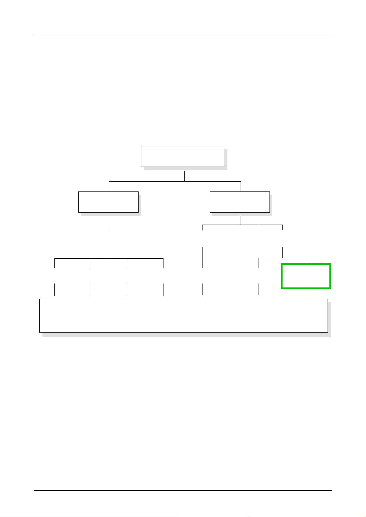
System 200V
central
DP 200V
PC 200V
PLC 200V
Profib u s Devic e N e t C A N Inter b u s PC-C PU P L C-CPU P L C-C PU
for STEP®5 of Siemens for STEP®7 of Siemens
peripheral
Dig. IN / Dig. OUT / Anal. IN / Anal. OUT / FM / CP
Overview
Manuals
The current manual describes the PLC-CPU f amily CPU 21x compatible to
STEP
The description of the PLC-CPU- family CPU 24x compatible to STEP
Siemens is available in the manual No. HB99.
The peripheral modules, PCs and decentr alized peripheral equipment are
to find in the manual HB97 " System 200V". T his manual also cont ains hints
for installation and commissioning of the System 200V.
7 by Siemens.
5 by
HB103E - Rev. 05/45 1-5
Page 18

Chapter 1 Principles Manual VIPA CPU 21x
Function security of the VIPA CPUs
The CPUs include security mechanisms like a Watchdog (100ms) and a
parameterizable cycle time surveillance (parameterizable min. 1ms) that
stop res. execute a RESET at the CPU in case of an error and set it into a
defined STOP state.
The VIPA CPUs are developed function secure and have the following
system properties:
Event concerns Effect
RUN → STOP
central digital outputs The outputs are set to 0V.
central analog outputs The voltage supply for the output channels is
decentral outputs The outputs are set to 0V.
decentral inputs The inputs are read constantly from the slave and
STOP → RUN
res. Power on
central analog outputs The behavior of the outputs at restart can be
decentral inputs The inputs are read constantly from the slave and
RUN general The program execution happens cyclically and can
PII: = Process image inputs
PIO: = Process image outputs
general
general First the PII is deleted, the call of the OB100
BASP (Befehls-Ausgabe-Sperre, i.e. command
output lock) is set.
switched off.
the recent values are put at disposal.
follows. After the execution of t he OB, the BASP is
set back and the cycle starts with:
Delete PIO → Read PII → OB1.
preset.
the recent values are put at disposal.
therefore be foreseen:
Read PII → OB1 → Write PIO.
1-6 HB103E - Rev. 05/45
Page 19
Manual VIPA CPU 21x Chapter 1 Principles
General description of the System 200V
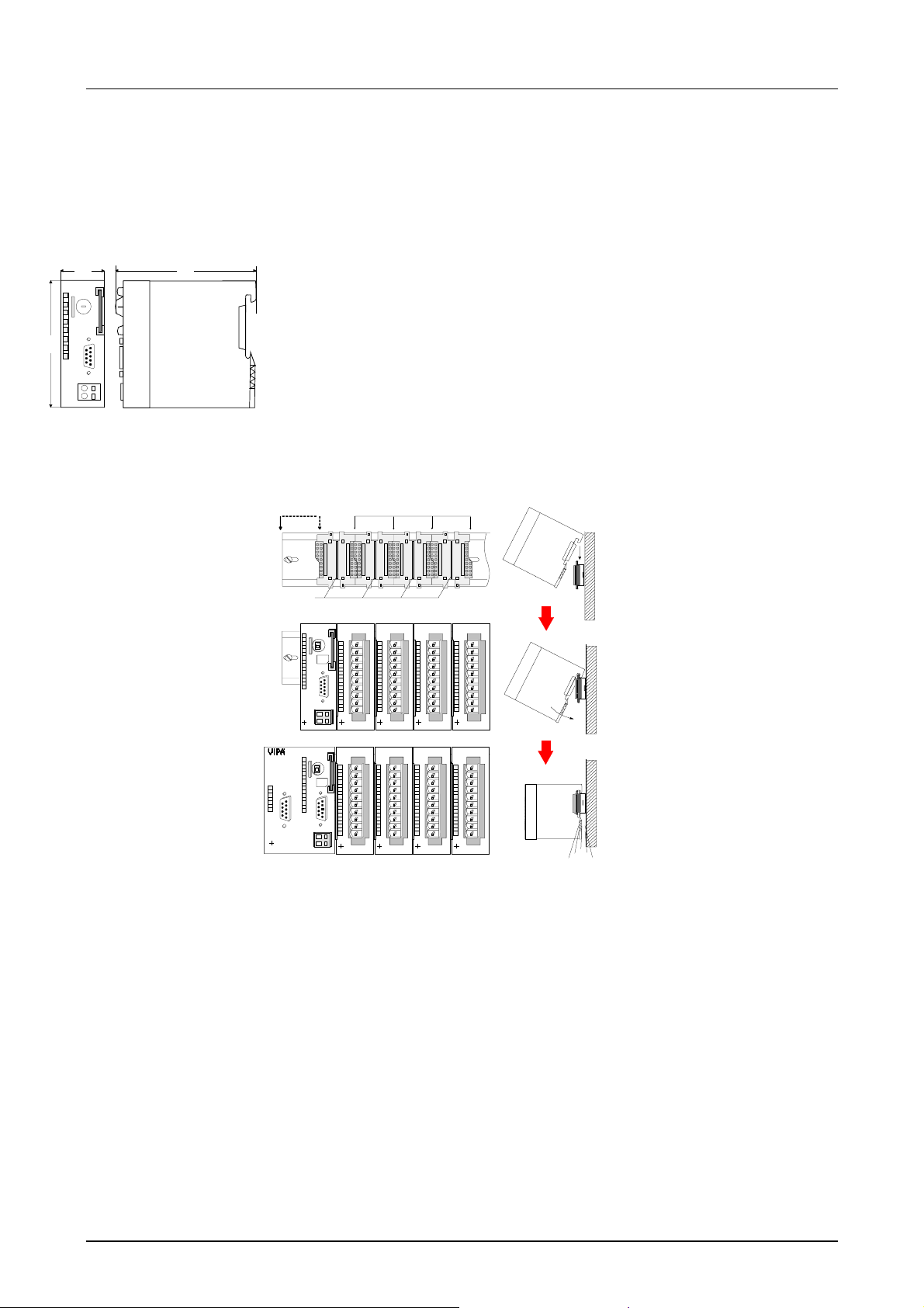
Structure /
Dimensions
W
D
• Norm profile head rail 35mm
• Peripheral modules with labeling strip
• Measurements basic module:
Single width: (HxWxD) in mm: 76x25.4x80; in inches: 3x1x3
Double width: (HxWxD) in mm: 76x50.8x80; in inches: 3x2x3
H
Installation
Please note, that you have to plug in the CPU only at plug-in location 1
resp. 1 and 2 (if double width).
12
3
[1] CPU if double width
[2] CPU single width
[3] peripheral modules
[4] leading bars
ER
RD
DE
X2
34
VIPA 216-2BP02
IM 253 CAN
ADR.
DC
24V
X5
X2
67
34
VIPA 253-1CA00
VIPA 216-2BA01
CPU 216DP
D
P
DC
24V
4
CPU 216
R
PW
ER
S
RD
PW
BA
SF
FC
MC
DC24V
+
+
-
-
R
S
PW
SF
FC
MC
+
-
MMC
01
MMC
RN
ST
MR
M
2
P
I
X1
1
1
2
2
RN
ST
MR
M
2
P
I
X1
1
2
SM 221
DI 8xDC24V
.0
.1
.2
.3
.4
.5
.6
.7
2
X
34
VIPA 221-1BF00
SM 221
DI 8xDC24V
.0
.1
.2
.3
.4
.5
.6
.7
2
X
34
VIPA 221-1BF00
SM 221
DI 8xDC24V
1
.0
2
.1
3
.2
4
.3
5
.4
6
.5
7
.6
8
.7
9
I0
2
X
34
VIPA 221-1BF00
SM 221
DI 8xDC24V
1
.0
2
.1
3
.2
4
.3
5
.4
6
.5
7
.6
8
.7
9
I0
2
X
34
VIPA 221-1BF00
SM 221
DI 8xDC24V
1
.0
2
.1
3
.2
4
.3
5
.4
6
.5
7
.6
8
.7
9
I0
2
X
34
VIPA 221-1BF00
SM 221
DI 8xDC24V
1
.0
2
.1
3
.2
4
.3
5
.4
6
.5
7
.6
8
.7
9
I0
2
X
34
VIPA 221-1BF00
SM 221
DI 8xDC24V
1
.0
2
.1
3
.2
4
.3
5
.4
6
.5
7
.6
8
.7
9
I0
2
X
34
VIPA 221-1BF00
SM 221
DI 8xDC24V
1
.0
2
.1
3
.2
4
.3
5
.4
6
.5
7
.6
8
.7
9
I0
2
X
34
VIPA 221-1BF00
1
2
3
4
5
6
7
8
9
I0
1
2
3
4
5
6
7
8
9
I0
Clack
Operating security
• Plug in via CageClamps at the front-facing connector, core cross-
section 0.08...2.5mm
2
resp. 1.5 mm2 (18pin plug)
• Total isolation of the cables during module changes
• Potential separation of all modules to the backplane bus
• EMC-proof ESD/Burst acc. EN61000-4-2/EN61000-4-4
to Level 3: 8kV/2.5kV
• Shock resistance acc. IEC 60068-2-6 / I EC 60068- 2- 27 ( 1G /12G)
Environmental
conditions
• Operating temperature: 0... +60°C
• Storage temperature: -40... +85°C
• Relative humidity: 95% without condensation
• fan-less operation
HB103E - Rev. 05/45 1-7
Page 20

Chapter 1 Principles Manual VIPA CPU 21x
Overview CPU 21x
General
Products
A CPU is an intelligent module. Your controlling programs are executed
here. You are able to select one of three CPUs, depending on the
performance required f r om your system. The hig her t he perf ormance of the
CPU, the more user memory is available.
The CPUs 21x are intended for small to medium applications and have an
integrated 24V power supply. The CPUs contain a standard processor with
internal program memory for the storage of user-programs. In addition,
every CPU 21x is equipped with a socket for a memory module, which is
located on the front.
Every CPU has an MPI-interface and is instruction set compatible with
®
STEP
performance as the Siemens STEP
7 from Siemens. The CPU series 214...216 have similar
®
7 CPU series.
This series of CPUs provides access to the peripheral modules of the
System 200V. You may quer y sensors and control actuators by means of
standardized commands and programs. The unit can address a maximum
of 32 modules. You may parameterize the CPU via the integrated MPIinterface.
The VIPA CPUs 21x are available in three differ ent performance categor ies
with 8 versions each:
• CPU 21x PLC-CPU
• CPU 21x-2BT02 PLC-CPU with Ethernet interface with H1 / TCP-IP
• CPU 21x-2BT10 PLC-CPU with Ethernet interface with TCP-IP
• CPU 21xDP PLC-CPU with Profibus slave
• CPU 21xDPM PLC-CPU with Profibus master
• CPU 21xSER-1 PLC-CPU with 1 serial interface
• CPU 21xSER-2 PLC-CPU with 2 serial interfaces
• CPU 21xCAN PLC-CPU with CANopen master
In all three performance categories, the CPUs 21x are available as
CPU 214, 215 and 216. Within these three performance categories, the
CPUs are visually on the same lines. With rising number the scope of
performance of a CPU 21x is increasing .
Note!
The remainder of this description ref ers to all CPUs of the VIPA CPU 21x
family!
1-8 HB103E - Rev. 05/45
Page 21

Manual VIPA CPU 21x Chapter 1 Principles
Hints for project engineering
Outline
Preconditions
For the project engineering of the CPU 21x and the other System 200V
modules connected to the same VIPA bus, you use the hardware
configurator from Siemens.
To address the directly plugged peripher al modules, you have to assign a
special address in the CPU to every one.
The address allocation and the parameterization of the modules takes
place in the SIMATIC manager fr om Siemens in form of a virtual Profibus
system. For the Profibus interface is standardized software sided, the
functionality is guaranteed by including a GSD-file into the SIMATIC
manager from Siemens.
Transfer your project into the CPU via the MPI interface.
For the project engineering of your CPU 21x the following requirements
have to be fulfilled:
• SIMATIC manager from Siem ens is installed at your PC resp. PG.
• The GSD-file for the System 200V is included to the hardware
configurator. Actual GSD files can be found at ftp://ftp.vipa.de/support.
• serial connection to the CPU (e.g. via "Green Cable" from VIPA)
Compatibility to
SIMATIC manager
from Siemens via
vipa_21x.gsd
GSD-file
Note!
The configuration of the CPU requires a thorough knowledge of the
Siemens SIMATIC manager and the hardware conf igurator!
The project engineer ing of a CPU 21x takes place via the SIMATIC manager from Siemens in form of a virtual Profibus system with the
CPU 315-2DP as basic.
Due to the standardized Profibus interface VIPA is able to support the
complete functionality of t he System 200V family in the SIMATIC manager
from Siemens by including the GSD-file vipa_21x.gsd.
To be compatib le with the SIMATIC manager from Siemens, t he following
steps have to take place:
• Project the Profibus-DP master system with CPU 315-2DP
(6ES7 315-2AF03 V1.2).
• Add Profibus slave "VIPA_CPU21x" from the HW catalog with address 1.
• Include the CPU 21x at the 1
st
slot of the slave system.
HB103E - Rev. 05/45 1-9
Page 22
Chapter 1 Principles Manual VIPA CPU 21x
A
Project
engineering
CPU 21x with
central periphery
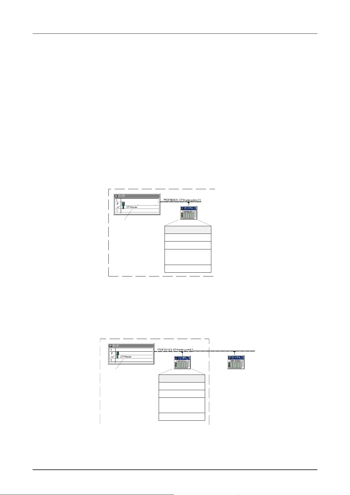
The following steps are necessary to project a CPU 21x in the hardware
configurator from Siemens:
• Start the hardware configurator from Siemens.
• Install the GSD-file VI PA_21x.gsd.
• Create a Profibus-DP master system with the CPU 315- 2DP.
• Include the master system from the hardware catalog in your slave
system "VIPA_CPU21x". You find this slave system in the hardware
catalog under Profibus-DP > Additional field devices > I/O >
VIPA_System_200V.
• Assign the address 1 to your slave system, so that the CPU is able to
recognize the system as central periphery system.
• Add your modules to the slave system in the same order you have
assembled them. Start with the CPU at t he 1
st
slot.
• Include then your System 200V modules.
CPU 21x
315-2DP (2AF03 -0AB0)
PB-
Addr.:1
PBAddr.:2
DP200V
Module
CPU 21x-xxxx
centralized periphery
.
.
.
centralized periphery
Master projecting
of the
CPU 21xDPM
When projecting a CPU 21xDPM you include the central modules like
described above. Slave systems that shall be connected t o the master are
added to the already existing master system:
CPU 21xDPM central
DP-Slaves decentral ...
PBAddr.:2
315-2DP (2AF03-0AB0)315-2DP (2AF03-0AB0)
PBAddr.:1
Module
CPU 21x-2BM02
centralized periphery
centralized periphery
.
.
.
DP200V
PB-
ddr.:3 ... 125
1-10 HB103E - Rev. 05/45
Page 23
Manual VIPA CPU 21x Chapter 1 Principles
Project
engineering of the
CPU 21xDP in a
master system
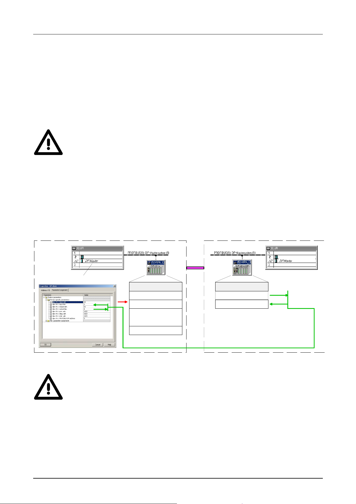
When configuring a CPU 21xDP, the central plugged-in modules are
parameterized like shown above.
Slave parameterization
As intelligent slave, the Profibus section maps its data areas into the
memory area of the CPU 21xDP. The assig nment of the areas is fixed via
the properties of t he CPU 21xDP. These ar eas have to be provided with an
according PLC program.
Attention!
The length values of input and output ar ea have to be identical to the byte
values of the master project eng ineering. Otherwise no Profibus communication is possible (slave failure).
Steps of project engineering in the DP master
• Configure the CPU with DP master system ( addr ess 2)
• Add Profibus slave VIPA_CPU2xxDP of VIPA04d5.gsd
• Assign Profibus input and output ar ea st ar ting with plug-in location 0
Slave: (VIPA_CPU21x of VIPA_21x.gsd)
Master: (VIPA_CPU21xDP of VIPA04d5.gsd)
315-2DP (2A F03-0AB0)
PBAdr.:2
IN
OUT
PBAdr.:1
centralized periphery
centralized periphery
DP200V CPU21x
Module
CPU 21x-2BP02
.
.
.
PBAdr.:5
Module
Output (Bytes)
Input m(Byte s)
315-2DP (2AF03-0AB0 )
Attention!
When using an IM 208DP master at a CPU 21x with firmware version
higher v3.0, you have to make sure that the master itself also has a
firmware version higher v3.0; otherwise the deployment of the IM 208DP is
not possible.
The according firmware version is to find on the label attached at the
backside of each module.
HB103E - Rev. 05/45 1-11
Page 24

Chapter 1 Principles Manual VIPA CPU 21x
Project
engineering
CPU 21xNET
Project
engineering
CPU 21xSER-1
Project
engineering
CPU 21xSER-2
The project engineering of network connections via Ethernet for the
CPU 21x-2BT02 can be carried out with WinNCS from VIPA and for the
CPU21x-2BT10 with SIMATIC Manager using NetPro.
The CP communication for the CPU 21x-2BS12 or CPU 21x-2BS32 is
accomplished via a send buffer and a receive buffer with a size of 256Byte.
Parameterization at runtime has to be carried out with the SFC 216
(SER_CFG). For all protocols except ASCII the parameters have to be
stored in a DB. Writing or reading the send buffer respectively receive
buffer can be controlled with the SFC 217 (SER_SND) respectively with the
SFC 218 (SER_RCV).
The CP of the CPU 21x-2BS02 is directly connected to the CPU part
through a Dual-Port-RAM, also called "page f rame". At the CPU this page
frame is available as standard CP interface. Communication on the
respective protocols is controlled by connection comm ands which have to
be programmed in the user application.
At this the VIPA-SFCs 230 ... 238 are used.
The parameter transfer to the communication processor (CP) is done at
runtime using a SEND (SFC 230) with order number 201. The parameters
have to be stored in a DB whose set-up depends on the desired protocol.
To activate the parameters a RESET ( SFC 234) has to be carried out with
order no. 0 after the SEND.
Project
engineering
CPU 21xCAN
Note!
Please regard that the commands SEND, RECEIVE, FETCH and RESET
require a preceding "VKE"=1 ot herwise they are not executed.
The project engineering of CANopen master will be done with WinCoCT
(Windows CANopen Configuration Tool) from VIPA.
Please export your project as wld file from WinCoCT, which can be
imported into the Hardware Configurator from Siemens. Therefor please
start a virtual Profibus system "VIPA_CPU21x" and integrate the CPU
21xCAN (VIPA 21x-2CM02) at slot 0.
1-12 HB103E - Rev. 05/45
Page 25
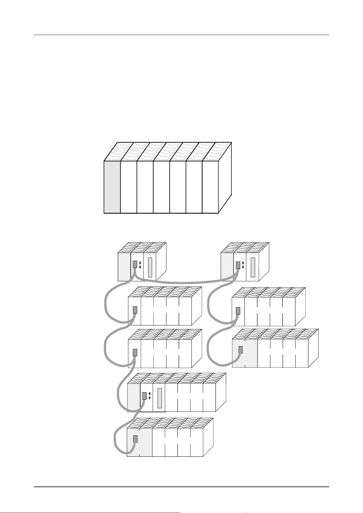
Manual VIPA CPU 21x Chapter 1 Principles
Application fields
Overview
Application
example
This series of CPU modules provides access to the per ipheral modules of
the VIPA System 200V. You can use a set of standard commands and
programs to interrogate sensors and actuators. One single CPU may
address a maximum of central 32 modules.
Compact centralized configuration
CPU
CPU 21x
AI 4 AO 4 DIO 8 DO 16
DO 8 Count
Decentralized configuration using Profibus
CPU IM 208
CPU IM 208
1,3
IM 253
Input/output periphery
1
IM 253
Input/output periphery
2
CPU IM 208
5
CPU 21x DP
2,4
IM 253
Input/output periphery
4
CPU 21x DP
Input/output periphery
5
Input/output periphery
Input/output periphery
3
HB103E - Rev. 05/45 1-13
Page 26
Chapter 1 Principles Manual VIPA CPU 21x
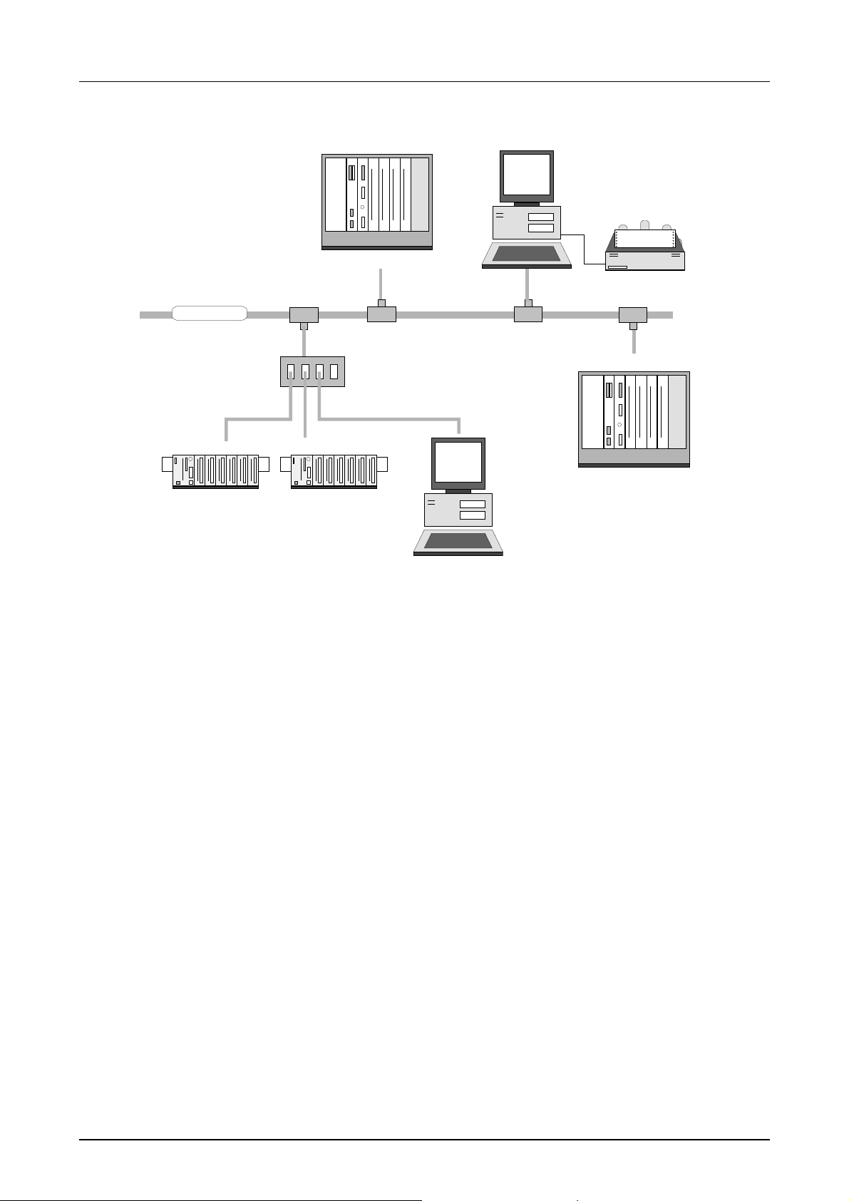
Application based on TCP/IP
TCP/IP
System 200V
CPU 21x NET
System 200V
CPU 21x NET
VIPA Rack-135U
CP 143 TCP/IP
Hub
Visualization and
shop floor data collection
via DDE-server
VIPA Rack-135U
CP 143 TCP/IP
Features
The PLC-CPUs are employed as program executor.
They support the input/output modules and process the data from the
function modules.
• Quick programm ing due to the compatibility with STEP
7 from Siemens.
• The compact construction requires less space.
• Enhanced flexibility provided by up to 32 function modules (DIG I/O,
ANA I/O, SSI, pulse counter, communication modules, etc.).
• Additional function modules can be added quickly and easily by means
of plug-in bus extension options.
• User-friendly maintenance using a PC via MPI.
• Optional Ethernet or Prof ibus interface.
1-14 HB103E - Rev. 05/45
Page 27

Manual VIPA CPU 21x Chapter 1 Principles
Operating modes of a CPU
General
Cyclic processing
Timer processing
These CPUs are intended for small and m edium sized applications and are
supplied with an integrated 24V power supply. The CPU contains a
standard processor with internal pr ogram memory. In combinat ion with the
System 200V peripherals the unit provides a powerful solution for process
automation applications within the System 200V family.
A CPU supports the following modes of oper ation:
• cyclic processing
• timer processing
• alarm controlled processing
• priority based processing
Cyclic processing represents the major portion of all the processes that
are executed in the CPU. Identical sequences of operations are repeated in
a never ending cycle.
Where a process requires control signals at constant intervals you can
initiate certain operations based upon a timer, e.g. not critical monitoring
functions at one-second intervals.
Alarm controlled
operation
Priority based
processing
If a process signal requir es a quick response you would allocate this signal
to an alarm controlled procedure. An alarm may activate a procedure in
your program.
The above processes are handled by the CPU in accordance with their
priority. Since a timer or an alarm event requires a quick reaction the CPU
will interrupt the cyclic processing when these high-priority events occur to
react to the event. Cyclic processing will resume once the reaction has
been processed. This means that cyclic processing has the lowest priority.
HB103E - Rev. 05/45 1-15
Page 28

Chapter 1 Principles Manual VIPA CPU 21x
CPU 21x programs
Overview
System routine
User program
The program that is pr esent in every CPU is divided as follows:
• System routine
• User program
The system routine organizes all those functions and procedures of the
CPU that are not related to a specific control application.
This consists of all the f unctions that are required for the processing of a
specific control application. The operating modules provide the interf aces
to the system routines.
CPU 21x operands
Overview
The following operands are available for pr ogramming the CPU 21x:
• Process image and periphery
• Bit memory/marker
• Timers and counters
• Data blocks
Process image
and periphery
1-16 HB103E - Rev. 05/45
The user program can quick ly access the process image of the inputs and
outputs PII/PIO. You may manipulate the following types of data:
- individual bits
- bytes
- words
- double words
You may also gain direct access to peripheral modules via the bus from
your user program. The following types of data are available:
- bytes
- words
- blocks
Page 29

Manual VIPA CPU 21x Chapter 1 Principles
Bit memory
Timer and counter
Data blocks
Bit memory is an ar ea of mem ory that is accessible to the user progr am by
means of certain operations. Bit memory is intended to store frequently
used working data.
You may access the following types of data:
- individual bits
- bytes
- words
- double words
With your program you may load a time cell with a value between 10ms
and 9990s. As soon as the user program executes a start operation the
value of this timer is decremented by the interval that you have specified
until it reaches zero.
You may load counter cells with an initial value (max. 999) and increm ent
or decrement this when required.
A data block contains constants or variables in form of bytes, words or
double words. You may always access the current data block by means of
operands.
You may access the following types of data:
- individual bits
- bytes
- words
- double words
HB103E - Rev. 05/45 1-17
Page 30

Chapter 1 Principles Manual VIPA CPU 21x
1-18 HB103E - Rev. 05/45
Page 31

Manual VIPA CPU 21x Chapter 2 Hardware description
Chapter 2 Hardware description
Outline
Contents
The CPUs 21x are available in different versions that are descr ibed in this
chapter. In addition to the hardware description the chapter also contains
installation and commissioning instructions and applications for the
memory modules.
The technical data conclude the chapter.
The following section contains descriptions of :
• the components of the CPUs along with controls and displays
• the modules integrated into t he CPU
• technical data
Topic Page
Chapter 2
System overview..................................................................................2-2
Structure ............................................................................................2-11
Components.......................................................................................2-13
Block diagram....................................................................................2-22
Technical data....................................................................................2-23
Hardware description .....................................................2-1
HB103E - Rev. 05/45 2-1
Page 32

Chapter 2 Hardware description Manual VIPA CPU 21x
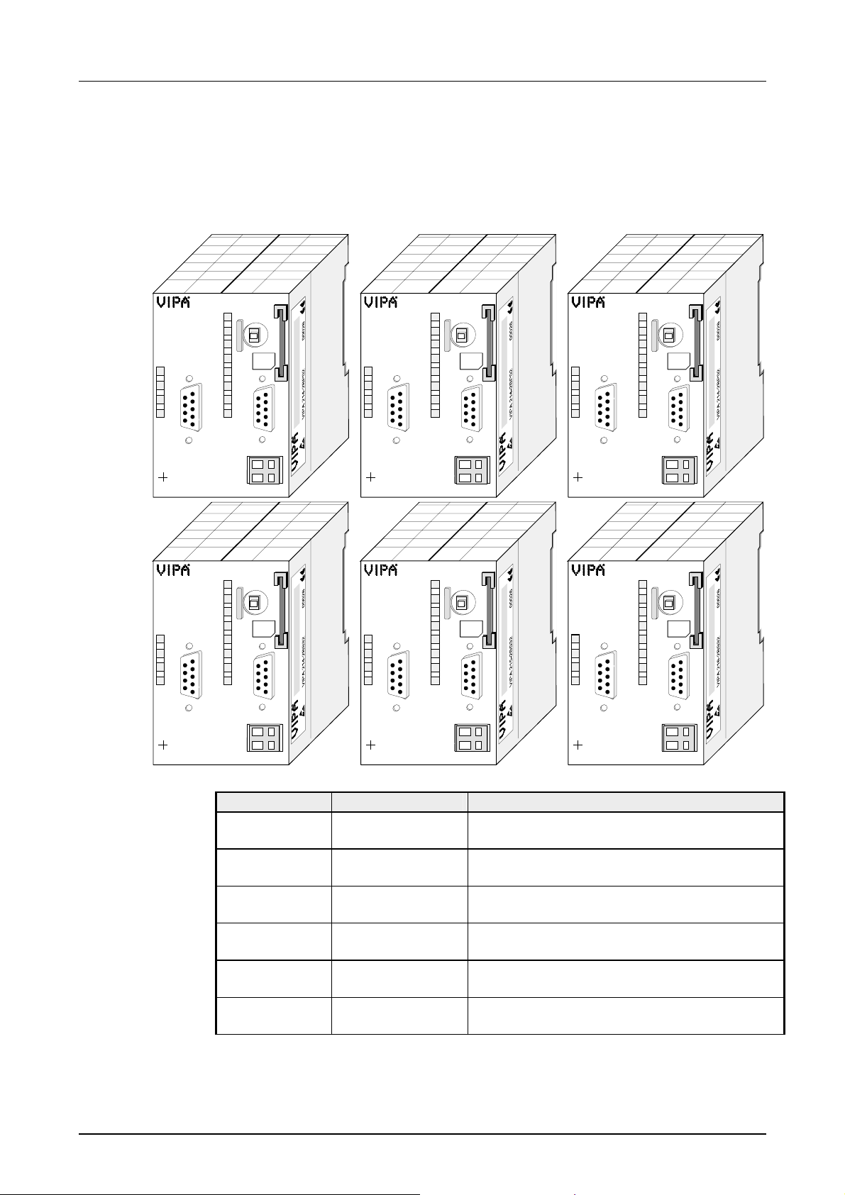
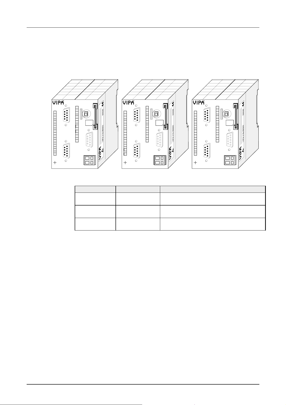
System overview
CPU versions
The CPU-21x family of products available from VIPA consists of 3 dif ferent
models each with 8 versions:
• CPU 21x PLC-CPU
• CPU 21x-2BT10 PLC-CPU with Ethernet interface with TCP-IP
• CPU 21x-2BT02 PLC-CPU with Ethernet interface with H1 / TCP-IP
• CPU 21xDPM PLC-CPU with Profibus master
• CPU 21xDP PLC-CPU with Profibus slave
• CPU 21xCAN PLC-CPU with CAN master
• CPU 21xSER-1 PLC-CPU with 1 serial interface
• CPU 21xSER-2 PLC-CPU with 2 serial interfaces
All CPUs 21x are available as CPU 214, 215 and 216. The CPUs 214,
215 and 216 are functionally identical and their only difference is the
memory size.
Note!
The remainder of this description refers to all CPUs of the CPU 21x family.
Properties
®
• Instruction set compatible to Siem ens STEP
7
• Configuration by means of the Siemens SIMATIC manager
• Integrated 24V power supply
• Total address range:
1024Byte inputs, 1024Byte outputs (128Byte process image each)
• 48...128kByte of work m em ory
• 80…192kByte of load memory
• Battery backed clock
• Memory-card slot
• MPI interface
• Integrated V-Bus controller for controlling System 200V peripherals
• User programs can be saved to the external memory card ( MMC)
• 256 timer
• 256 counter
• 8192 Bit memories
2-2 HB103E - Rev. 05/45
Page 33
Manual VIPA CPU 21x Chapter 2 Hardware description
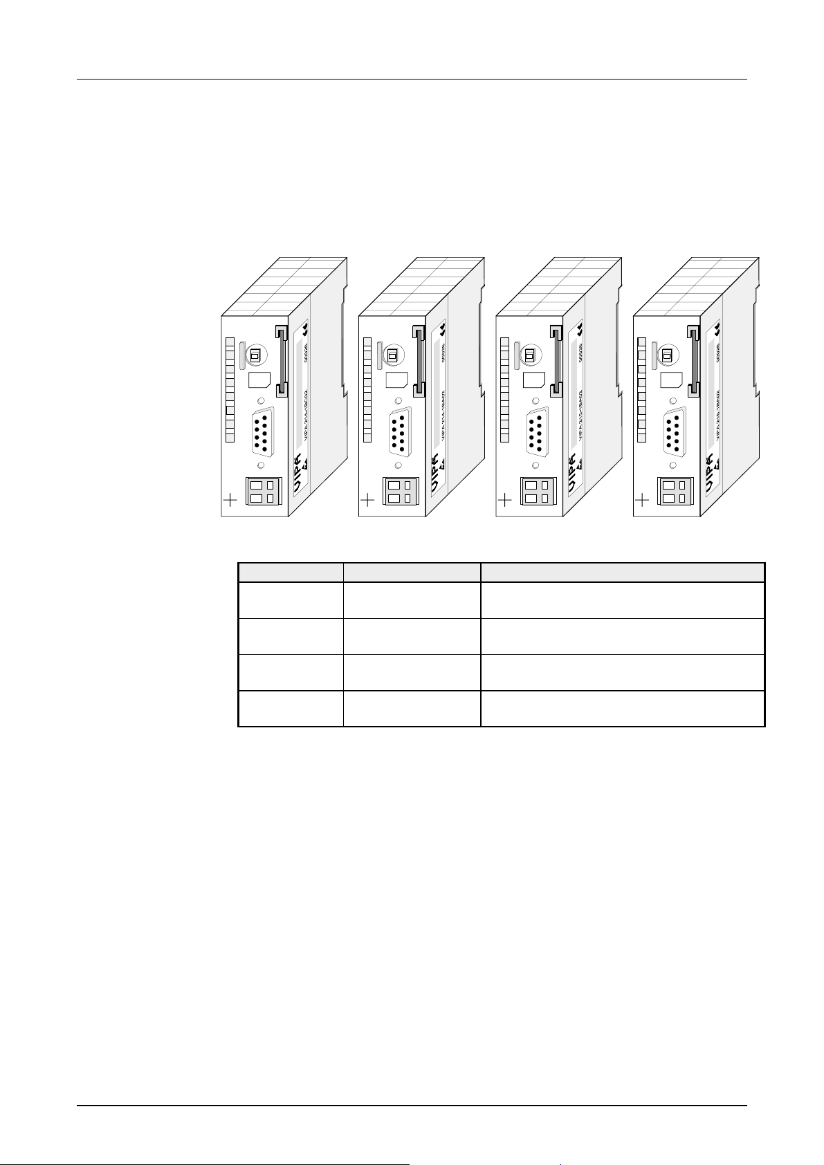
CPU 21x
• Instruction set compatible with Siemens STEP7
• MPI interface for data t r ansfer between PC and CPU
• Status LEDs for operating m ode and diagnostics
• External memory card (MMC)
• "On board" memory
CPU 214
RN
ST
R
MR
S
MMC
PW
SF
FC
MC
DC
24V
X2
34
VIPA 214-1BC02
X1
+
-
M
2
P
I
1
2
CPU 214
RN
ST
R
MR
S
MMC
PW
SF
FC
MC
DC
24V
X2
34
VIPA 214-1BA02
X1
+
-
CPU 215
RN
ST
R
MR
S
MMC
PW
M
2
P
I
1
2
SF
FC
MC
DC
24V
X2
34
VIPA 215-1BA02
X1
+
-
M
2
P
I
1
2
CPU 216
R
S
PW
SF
FC
MC
DC
+
24V
-
X2
34
VIPA 216-1BA02
MMC
RN
MR
ST
M
2
P
I
X1
1
2
Order data
CPU 21x
Type Order number Description
CPU 214C VIPA 214-1BC02 PLC CPU 214 with
32/40KB of work/load memory
CPU 214 VIPA 214-1BA02 PLC CPU 214 with
48/80KB of work/load memory
CPU 215 VIPA 215-1BA02 PLC CPU 215 with
96/144KB of work/load memory
CPU 216 VIPA 216-1BA02 PLC CPU 215 with
128/192KB of work/load memory
HB103E - Rev. 05/45 2-3
Page 34
Chapter 2 Hardware description Manual VIPA CPU 21x
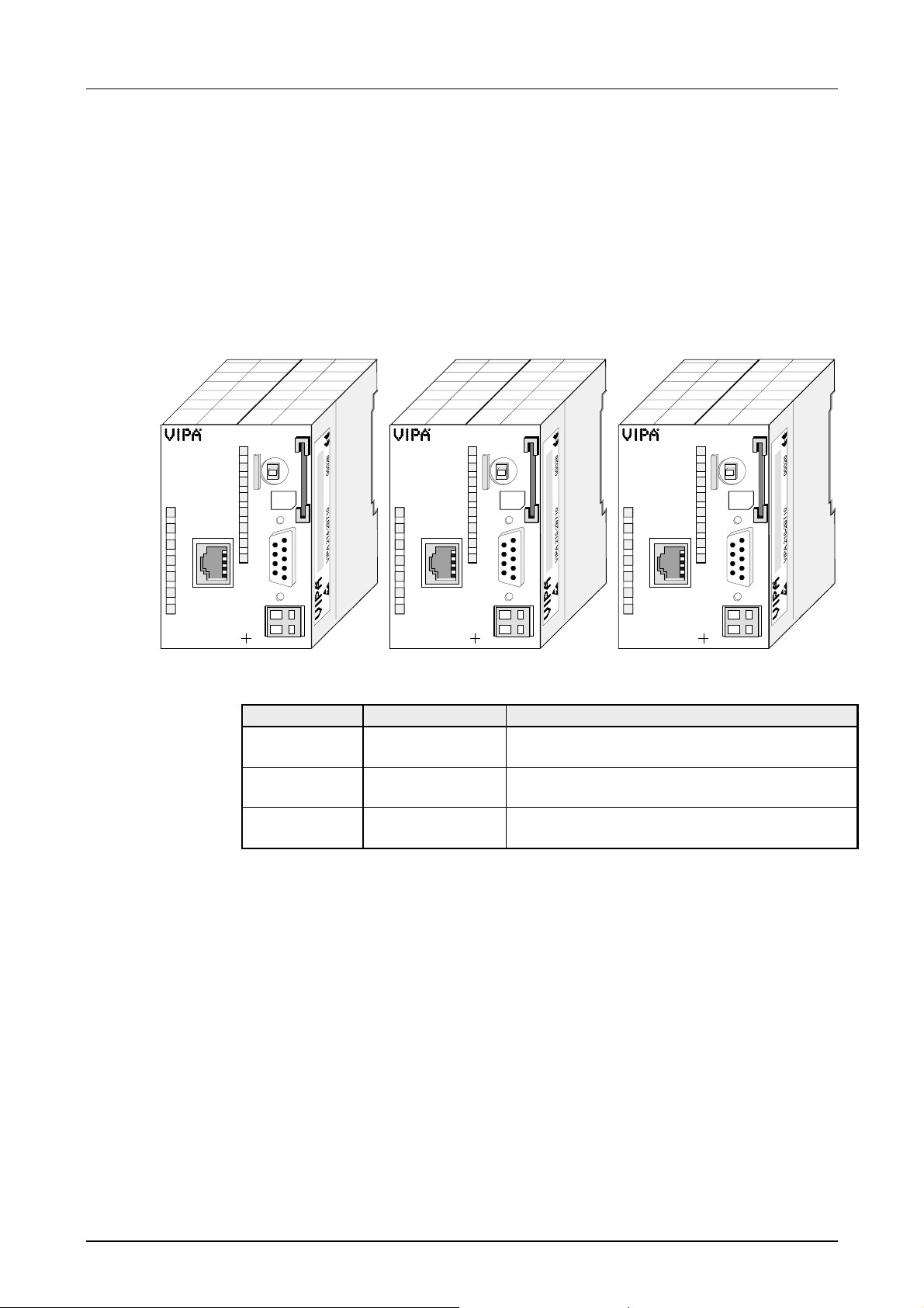
CPU 21x-2BT10
RN
10/100
ST
IF
L/A
S
VIPA 214-2BT10
CPU 214NET
R
S
PW
TP
SF
FC
MC
DC
24V
2
X
34
Identical to CPU 21x, additionally with:
• Integrated Ethernet CP 243 ( c om pat ible to CP 343)
• Direct connection to twisted pair Ethernet via RJ45 jack
• Protocols TCP/IP, UDP and RFC1006
• Transfer rate 10/ 100MBit/s
• PG/OP channel
• CP configurable with NetPro from Siemens
CPU 215NET
RN
ST
MR
MMC
TP
RN
10/100
M
2
P
I
X1
+
1
-
2
ST
IF
L/A
S
VIPA 215-2BT10
DC
24V
X
34
R
S
PW
SF
FC
MC
2
RN
ST
MR
MMC
M
2
P
I
X1
1
+
-
2
VIPA 216-2BT10
RN
ST
IF
L/A
S
CPU 216NET
TP
10/100
DC
24V
X
34
R
S
PW
SF
FC
MC
2
RN
ST
MR
MMC
M
2
P
I
X1
+
-
1
2
Order data
CPU 21xNET
Type Order number Description
CPU 214NET VIPA 214-2BT10 PLC CPU 214 with Ethernet and
48/80KB of work/load memory
CPU 215NET VIPA 215-2BT10 PLC CPU 215 with Ethernet and
96/144KB of work/load memory
CPU 216NET VIPA 216-2BT10 PLC CPU 216 with Ethernet and
128/192KB of work/load memory
2-4 HB103E - Rev. 05/45
Page 35
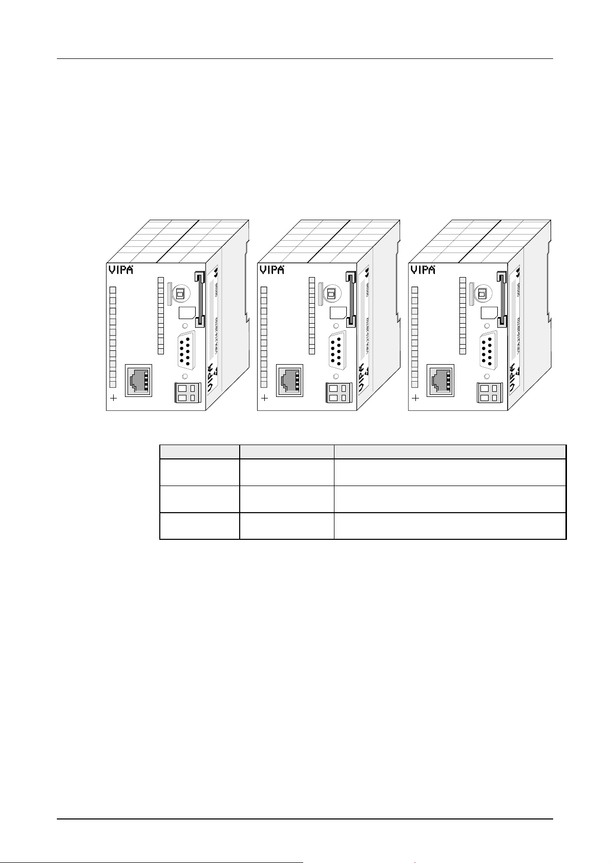
Manual VIPA CPU 21x Chapter 2 Hardware description
CPU 21x-2BT02
PW
Tx
Rx
TP
IX-Data
2
X
34
VIPA 214-2BT02
Identical to CPU 21x, additionally with:
• Integrated Ethernet CP 243
• Direct connection of twisted pair Ethernet via RJ45 jack
• Protocols H1, TCP/IP, UDP
• Transfer rate 10MBit/s
• CP parameterizable with W inNCS
CPU 214NET
R
S
MMC
PW
SF
FC
MC
DC
+
24V
-
RN
ST
MR
M
2
P
I
X1
1
2
X
34
VIPA 215-2BT02
PW
Tx
Rx
2
TP
IX-Data
CPU 215NET
R
S
MMC
PW
SF
FC
MC
DC
+
24V
-
RN
ST
MR
M
2
P
I
X1
1
2
CPU 216NET
PW
Tx
Rx
TP
IX-Data
2
X
34
VIPA 216-2BT02
DC
24V
R
S
PW
SF
FC
MC
RN
ST
MR
MMC
M
2
P
I
X1
+
-
1
2
Order data
CPU 21xNET
Type Order number Description
CPU 214NET VIPA 214-2BT02 PLC CPU 214 with Ethernet and
48/80KB of work/load memory
CPU 215NET VIPA 215-2BT02 PLC CPU 215 with Ethernet and
96/144KB of work/load memory
CPU 216NET VIPA 216-2BT02 PLC CPU 216 with Ethernet and
128/192KB of work/load memory
HB103E - Rev. 05/45 2-5
Page 36
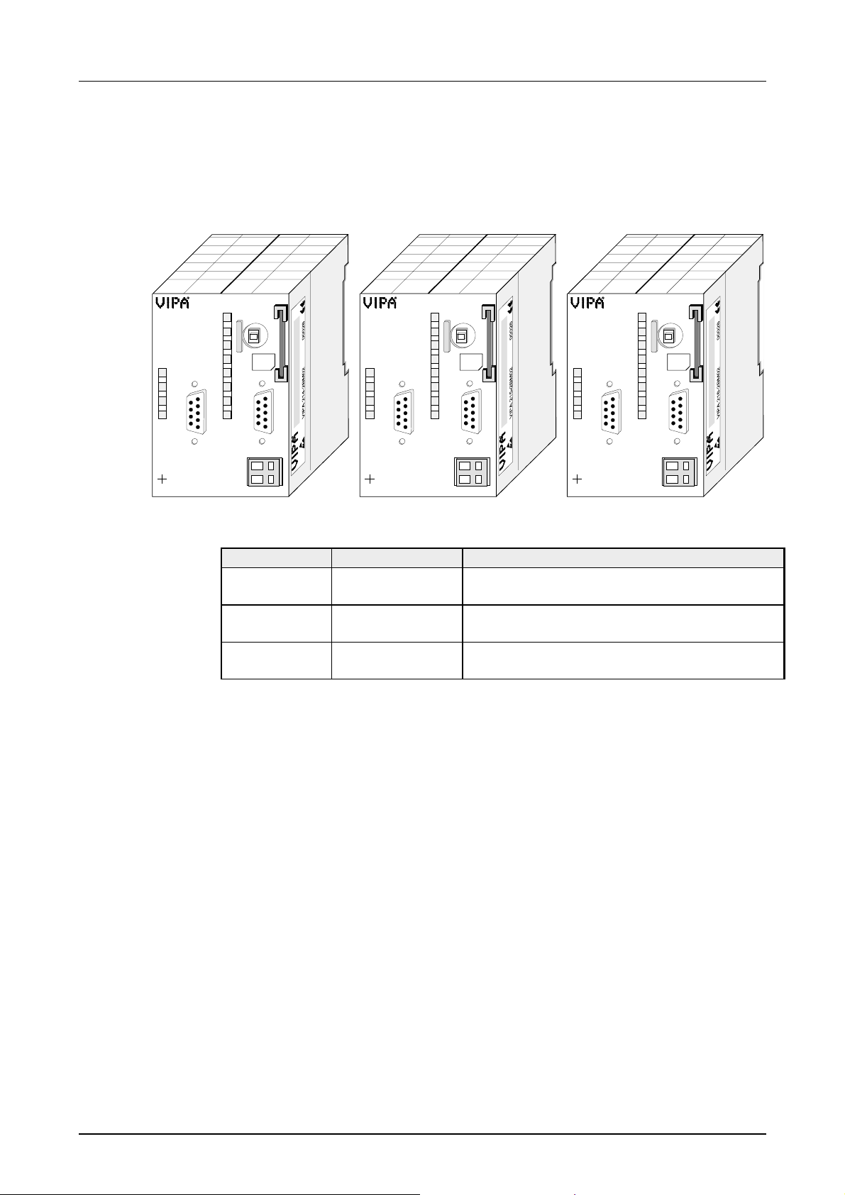
Chapter 2 Hardware description Manual VIPA CPU 21x
CPU 21xDPM
RN
IF
DE
ER
2
X
34
VIPA 214-2BM02
Identical to CPU 21x, additionally with:
• Integrated Prof ibus- DP m ast er
• Status-LEDs for Profibus status and diagnostics
CPU 214DPM
R
S
MMC
PW
SF
FC
D
MC
P
DC
+
24V
-
RN
ST
MR
M
2
P
I
X1
1
2
X
34
VIPA 215-2BM02
RN
IF
DE
ER
2
CPU 215DPM
R
S
MMC
PW
SF
FC
D
MC
P
DC
+
24V
-
RN
ST
MR
M
2
P
I
X1
1
2
CPU 216DPM
RN
IF
DE
D
ER
P
2
X
34
VIPA 216-2BM02
DC
24V
RN
R
ST
MR
S
MMC
PW
SF
FC
MC
M
2
P
I
X1
+
1
-
2
Order data
CPU 21xDPM
Type Order number Description
CPU 214DPM VIPA 214-2BM02 PLC CPU 214 with Profibus-DP mast er and
48/80KB of work/load memory
CPU 215DPM VIPA 215-2BM02 PLC CPU 215 with Profibus-DP mast er and
96/144KB of work/load memory
CPU 216DPM VIPA 216-2BM02 PLC CPU 216 with Profibus-DP mast er and
128/192KB of work/load memory
2-6 HB103E - Rev. 05/45
Page 37
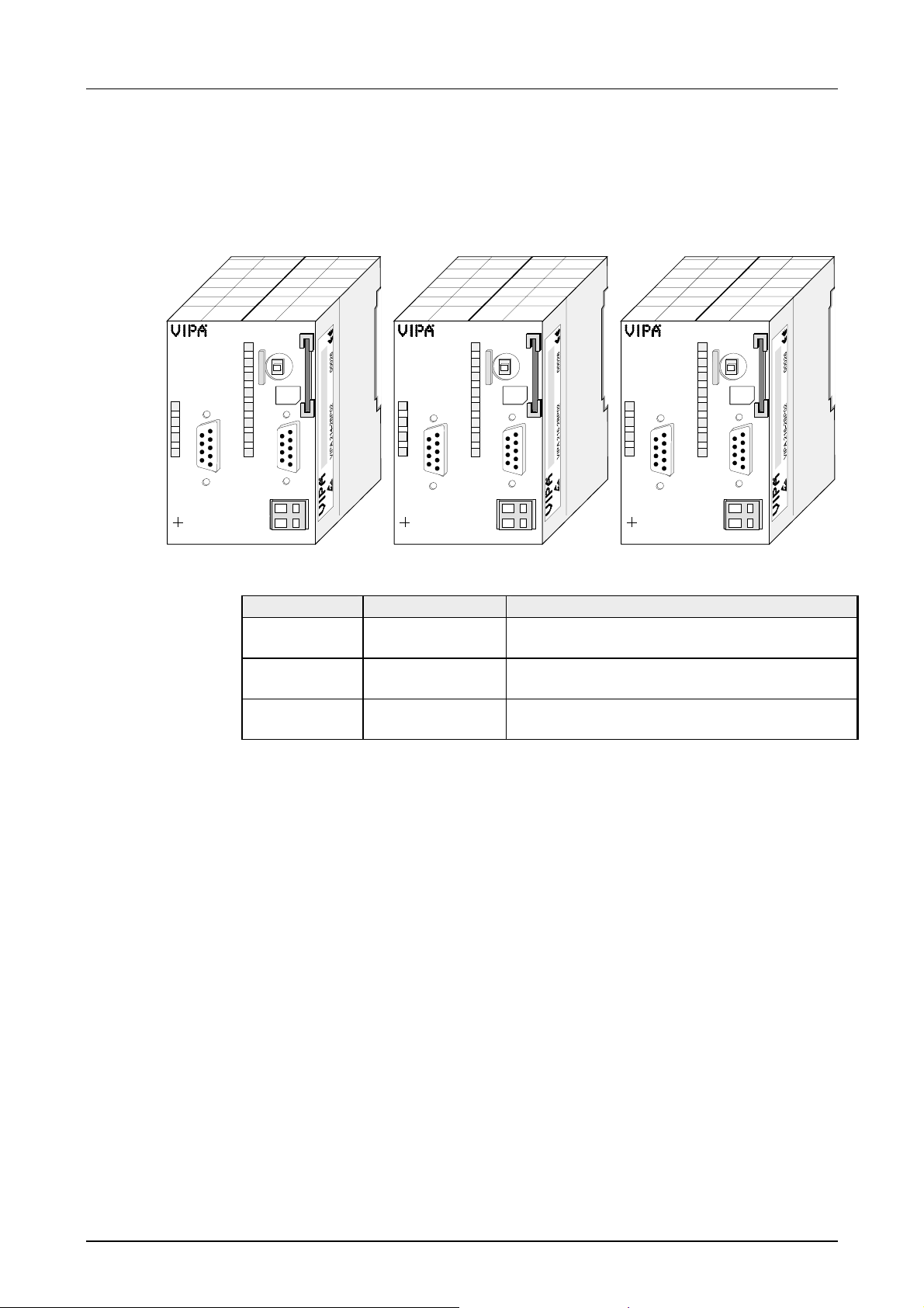
Manual VIPA CPU 21x Chapter 2 Hardware description
CPU 21xDP
X2
34
VIPA 214-2BP02
Identical to CPU 21x, additionally with:
• Integrated Prof ibus slave
• Status LEDs for Profibus status and diagnostics
CPU 214DP
RN
R
ST
MR
S
MMC
ER
RD
DE
PW
SF
FC
D
MC
P
DC
24V
M
2
P
I
X1
1
+
-
2
ER
RD
DE
X2
34
VIPA 215-2BP02
CPU 215DP
R
S
PW
SF
FC
D
MC
P
DC
+
24V
CPU 216DP
RN
ST
MR
MMC
ER
M
2
P
I
X1
1
-
2
RD
D
DE
P
X2
34
VIPA 216-2BP02
DC
24V
RN
R
ST
MR
S
MMC
PW
SF
FC
MC
M
2
P
I
X1
+
1
-
2
Order data
CPU 21xDP
Type Order number Description
CPU 214DP VIPA 214-2BP02 SPS CPU 214 with Profibus slave and
48/80KB of work/load memory
CPU 215DP VIPA 215-2BP02 SPS CPU 215 with Profibus slave and
96/144KB of work/load memory
CPU 216DP VIPA 216-2BP02 SPS CPU 216 with Profibus slave and
128/192KB of work/load memory
HB103E - Rev. 05/45 2-7
Page 38
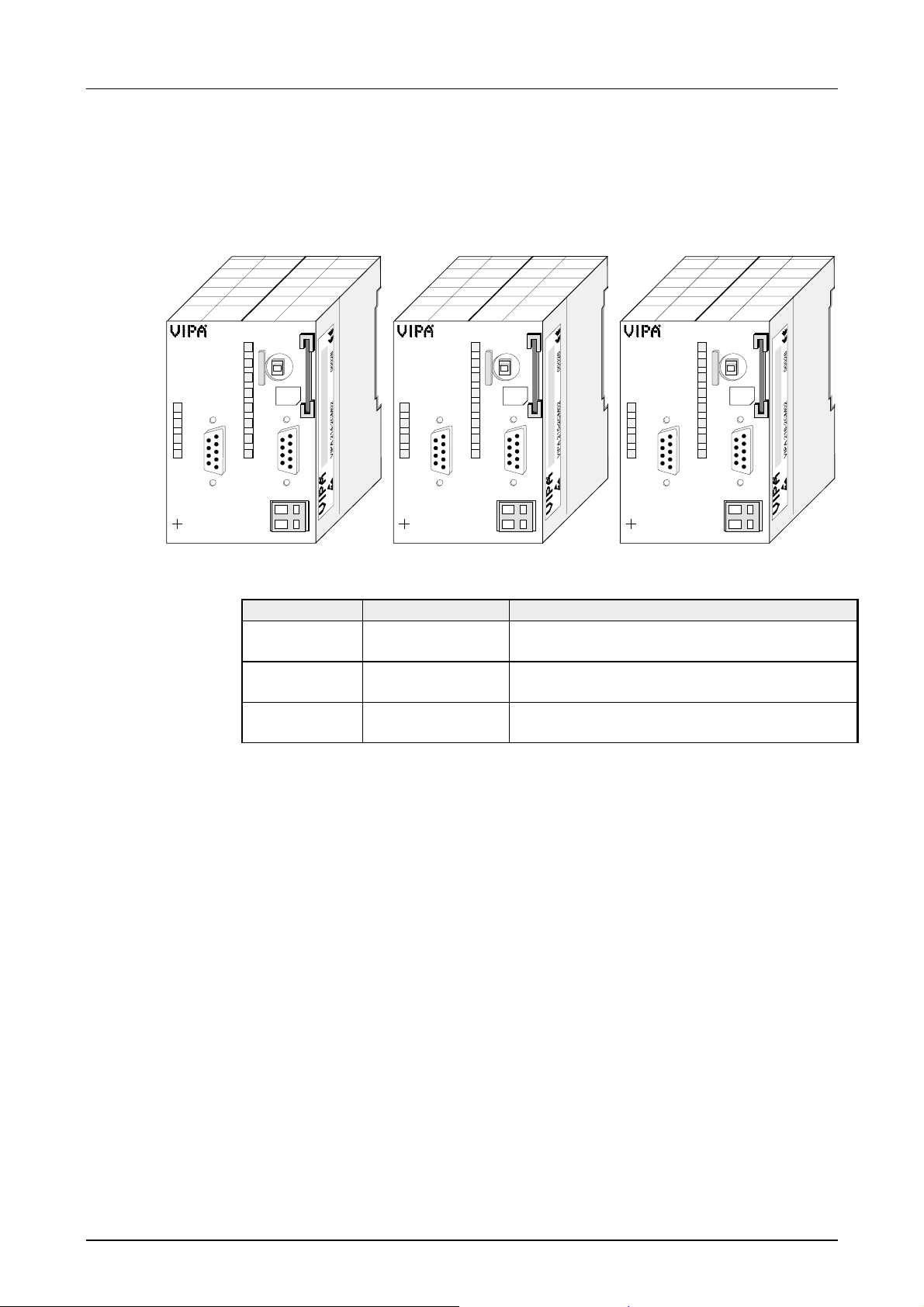
Chapter 2 Hardware description Manual VIPA CPU 21x
CPU 21xCAN
RN
IF
DE
ER
2
X
34
VIPA 214-2CM02
Identical to CPU 21x, additionally with:
• Integrated CAN master
• Status-LEDs for CAN status and diagnostics
CPU 214CAN
R
S
MMC
PW
SF
FC
C
A
MC
N
DC
+
24V
-
RN
ST
MR
M
2
P
I
X1
1
2
X
34
VIPA 215-2CM02
RN
IF
DE
ER
2
CPU 215CAN
R
S
MMC
PW
SF
FC
C
A
MC
N
DC
+
24V
-
RN
ST
MR
M
P
I
X1
CPU 216CAN
RN
R
ST
MR
S
DC
24V
MMC
PW
SF
FC
MC
M
2
P
I
X1
+
1
-
2
RN
IF
DE
2
1
2
2
X
34
VIPA 216-2CM02
C
A
ER
N
Order data
CPU 21xCAN
Type Order number Description
CPU 214CAN VIPA 214-2CM02 PLC CPU 214 with CAN master and
48/80KB of work/load memory
CPU 215CAN VIPA 215-2CM02 PLC CPU 215 with CAN master and
96/144KB of work/load memory
CPU 216CAN VIPA 216-2CM02 PLC CPU 216 with CAN master and
128/192KB of work/load memory
2-8 HB103E - Rev. 05/45
Page 39
Manual VIPA CPU 21x Chapter 2 Hardware description
CPU 21xSER-1
Rx
Tx
X2
34
VIPA 214-2BS12
Identical to CPU 21x, additionally with:
• Serial Communication via two COM interfaces (RS232C or RS485)
• LEDs for communication
CPU 214SER
R
S
PW
SF
C
FC
O
MC
M
DC
+
24V
-
MMC
RN
ST
MR
M
2
P
I
X1
1
2
X2
34
VIPA 215-2BS12
Rx
Tx
CPU 215SER
R
S
PW
SF
C
FC
O
MC
M
DC
+
24V
-
MMC
CPU 216SER
RN
ST
MR
Rx
C
M
2
P
I
X1
1
2
Tx
O
M
X2
34
VIPA 216-2BS12
DC
24V
RN
R
ST
MR
S
MMC
PW
SF
FC
MC
M
2
P
I
X1
+
1
-
2
Rx
Tx
X2
34
VIPA 214-2BS32
Order data
CPU 21xSER-1
CPU 214SER
R
S
PW
SF
C
FC
O
MC
M
DC
+
24V
-
MMC
RN
ST
MR
M
2
P
I
X1
1
2
X2
34
VIPA 215-2BS32
Rx
Tx
CPU 215SER
R
S
PW
SF
C
FC
O
MC
M
DC
+
24V
-
MMC
CPU 216SER
RN
ST
MR
Rx
C
M
2
P
I
X1
1
2
Tx
O
M
X2
34
VIPA 216-2BS32
DC
24V
RN
R
ST
MR
S
MMC
PW
SF
FC
MC
M
2
P
I
X1
+
1
-
2
Type Order number Description
CPU 214SER VIPA 214-2BS12 SPS CPU 214 with 1xRS232C interface and
48/80kByte of work/load memor y
CPU 215SER VIPA 215-2BS12 SPS CPU 215 with 1xRS232C interface and
96/144kByte of work/load memor y
CPU 216SER VIPA 216-2BS12 SPS CPU 216 with 1xRS232C interface and
128/192kByte of work/load memor y
CPU 214SER VIPA 214-2BS32 SPS CPU 214 with 1xRS485 interface and
48/80kByte of work/load memor y
CPU 215SER VIPA 215-2BS32 SPS CPU 215 with 1xRS485 interface and
96/144kByte of work/load memor y
CPU 216SER VIPA 216-2BS32 SPS CPU 216 with 1xRS485 interface and
128/192kByte of work/load memor y
HB103E - Rev. 05/45 2-9
Page 40
Chapter 2 Hardware description Manual VIPA CPU 21x
CPU 21xSER-2
RN
ER1
Rx1
Tx1
ER2
Rx2
Tx2
X2
4
3
VIPA 214-2BS02
Identical to CPU 21x, additionally with:
• Serial Communication via 2 RS232C interfaces
• LEDs for Communication
CPU 214SER
C
R
O
M
S
1
C
O
M
2
DC
24V
MMC
PW
SF
FC
MC
+
-
RN
ST
MR
M
2
P
I
X1
1
2
X2
4
3
VIPA 215-2BS02
RN
ER1
Rx1
Tx1
ER2
Rx2
Tx2
CPU 215SER
C
R
O
M
S
1
C
O
M
2
DC
24V
MMC
PW
SF
FC
MC
+
-
RN
ST
MR
M
2
P
I
X1
1
2
CPU 216SER
C
RN
O
M
ER1
1
Rx1
Tx1
ER2
Rx2
Tx2
C
O
M
2
X2
4
3
VIPA 216-2BS02
DC
24V
RN
R
ST
MR
S
MMC
PW
SF
FC
MC
M
2
P
I
X1
+
1
2
-
Order data
CPU 21xSER-2
Type Order number Description
CPU 214SER VIPA 214-2BS02 SPS CPU 214 with 2xRS232C interface
and 48/80kByte of work/load memor y
CPU 215SER VIPA 215-2BS02 SPS CPU 215 with 2xRS232C interface
and 96/144kByte of work/load memor y
CPU 216SER VIPA 216-2BS02 SPS CPU 216 with 2xRS232C interface
and 128/192kByte of work/load memor y
2-10 HB103E - Rev. 05/45
Page 41
Manual VIPA CPU 21x Chapter 2 Hardware description
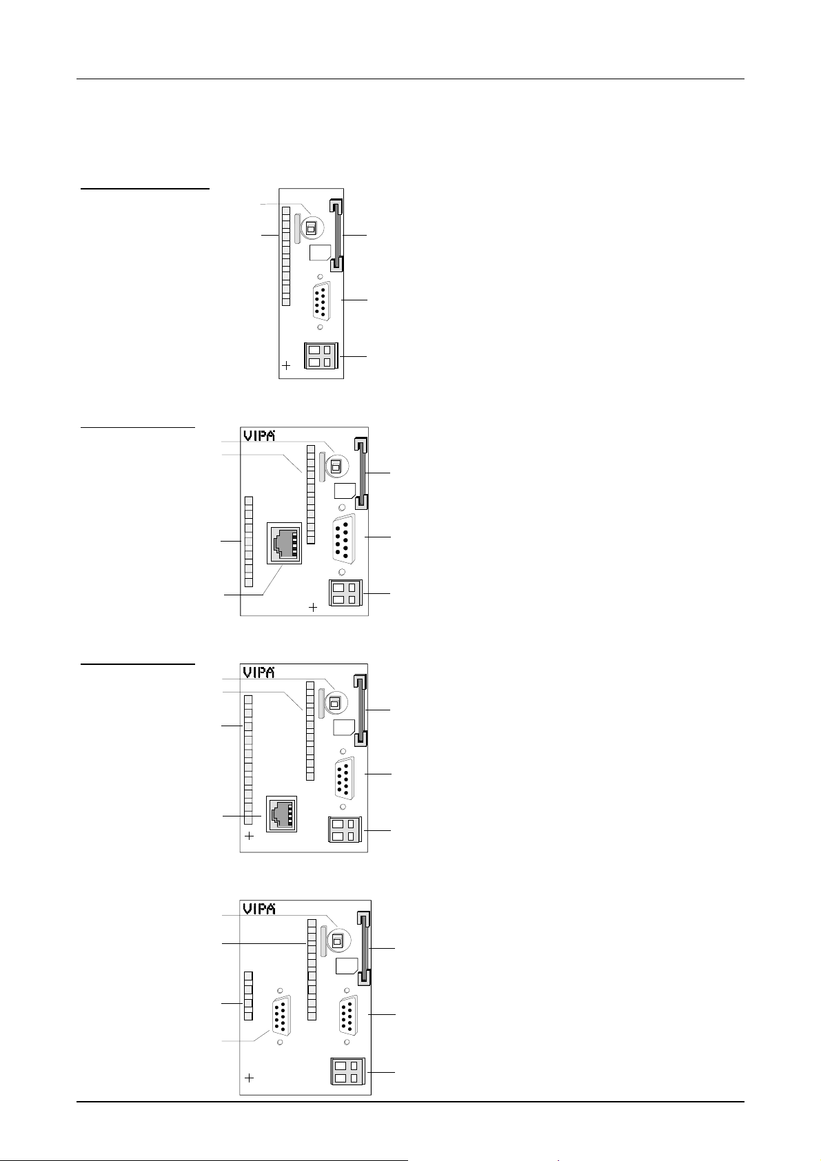
Structure
Front view
CPU 21x
Front view
CPU 21x-2BT10
1
2
6
7
1
2
RN
ST
IF
L/A
S
VIPA 216-2BT10
CPU 216
RN
R
ST
MR
S
MMC
PW
SF
FC
MC
DC
+
24V
-
X2
34
VIPA 216-2BA02
CPU 216NET
R
S
PW
TP
SF
10/100
FC
MC
DC
+
24V
-
X2
34
[1] RUN/STOP/OVERALL RESET
function selector
3
M
2
P
X1
4
I
1
5
2
[2] Status indicator LEDs CPU
[3] Slot for MMC memory card
[4] MP
2
I interface
[5] Connector for 24V DC power supply
[1] RUN/STOP/OVERALL RESET
function selector
2
I interface
MMC
RN
ST
MR
3
[2] Status indicator LEDs CPU
[3] Slot for MMC memory card
[4] MP
M
2
P
4
I
[5] Connector for 24V DC power supply
[6] Status indicator LEDs Ethernet
[7] RJ45 jack f or twisted pair Ethernet
X1
1
5
2
Front view
CPU 21x-2BT02
1
2
6
7
CPU 216NET
PW
Tx
Rx
TP
IX-Data
2
X
4
3
VIPA 216-2BT02
DC
24V
RN
R
ST
MR
S
MMC
PW
SF
FC
M
P
MC
X1
+
-
3
2
I
4
1
5
2
[1] RUN/STOP/OVERALL RESET
function selector
[2] Status indicator LEDs CPU
[3] Slot for MMC memory card
[4] MP
2
I interface
[5] Connector for 24V DC power supply
[6] Status indicator LEDs Ethernet
[7] RJ45 jack f or twisted pair Ethernet
Front view
CPU 21xDPM
1
2
6
7
CPU 216DPM
RN
IF
DE
D
ER
P
2
X
34
VIPA 216-2BM02
DC
24V
RN
R
ST
MR
S
MMC
PW
SF
FC
MC
M
2
P
I
X1
1
+
-
2
[1] RUN/STOP/OVERALL RESET
function selector
[2] Status indicator LEDs CPU
3
[3] Slot for MMC memory card
[4] MP
2
I interface
[5] Connector for 24V DC power supply
4
[6] Profibus-DP mast er status indicator
LEDs
[7] Profibus interface
5
HB103E - Rev. 05/45 2-11
Page 42
Chapter 2 Hardware description Manual VIPA CPU 21x
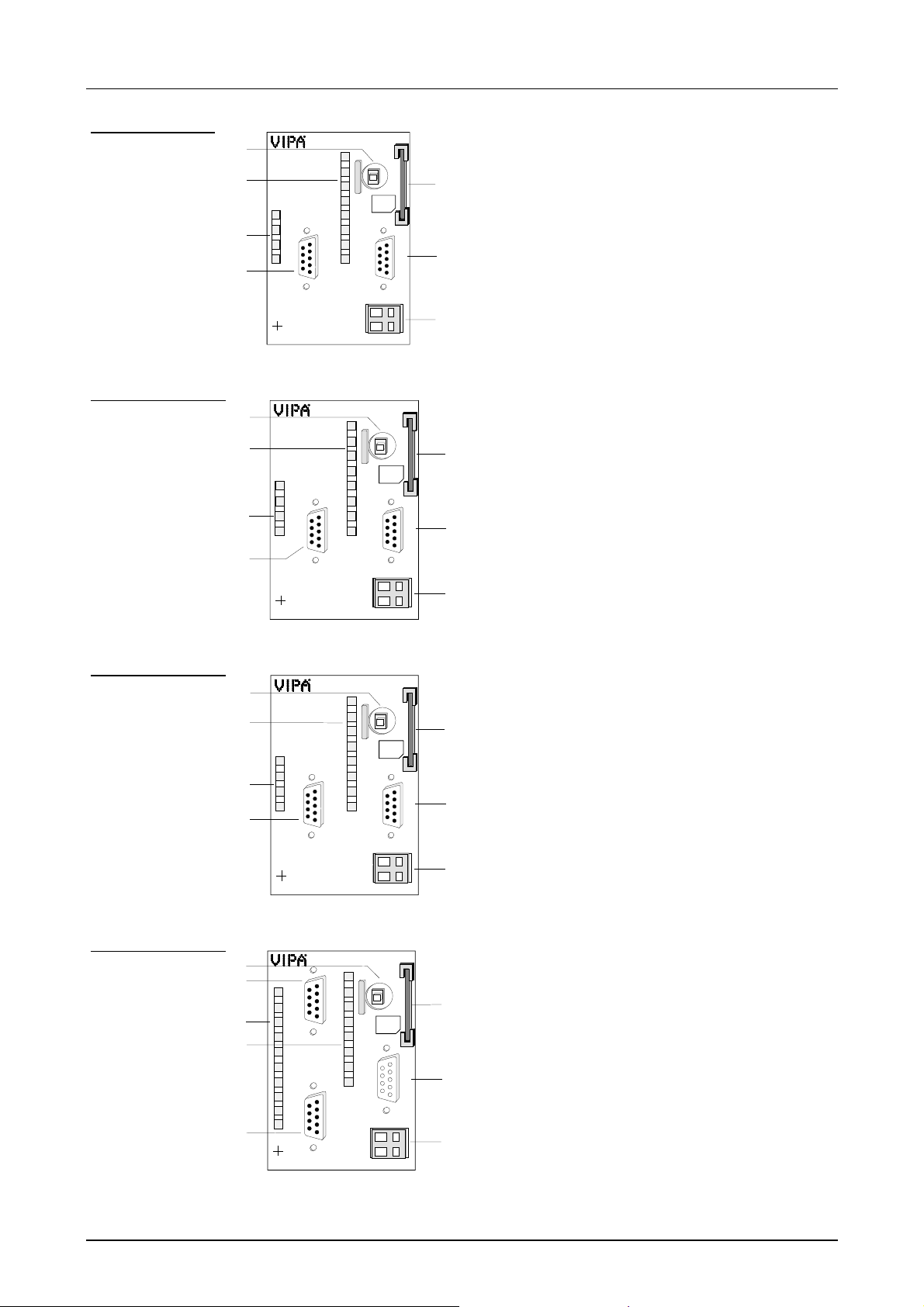
Front view
CPU 21xDP
Front view
CPU 21xCAN
1
2
6
7
1
2
6
7
ER
RD
DE
X2
34
VIPA 216-2BP02
RN
IF
DE
ER
2
X
34
VIPA 216-2CM02
CPU 216DP
R
S
PW
SF
FC
D
MC
P
DC
+
24V
-
CPU 216CAN
R
S
PW
SF
FC
C
A
MC
N
DC
+
24V
-
MMC
MMC
[1] RUN/STOP/OVERALL RESET
RN
ST
MR
3
[2] Status indicator LEDs CPU
[3] Slot for MMC memory card
[4] MP
M
2
P
I
4
[5] Connector for 24V DC power supply
[6] Status indicator LEDs Pr ofibus-DP
function selector
2
I interface
slave
X1
1
5
2
[7] Profibus DP inter face
[1] RUN/STOP/OVERALL RESET
RN
ST
MR
[2] Status indicator LEDs CPU
3
[3] Slot for MMC memory card
[4] MP
M
2
P
I
X1
1
2
[5] Connector for 24V DC power supply
4
[6] LEDs status indicator CAN mast er
[7] CAN interface
5
function selector
2
I interface
Front view
CPU 21xSER-1
Front view
CPU 21xSER-2
1
2
6
7
1
7
6
2
8
Rx
Tx
X2
34
VIPA 216-2BS12
RN
ER1
Rx1
Tx1
ER2
Rx2
Tx2
2
X
34
VIPA 216-2BS02
CPU 216SER
R
S
MMC
PW
SF
FC
C
O
MC
M
DC
+
24V
-
CPU 216SER
C
R
O
M
S
1
C
O
M
2
DC
24V
MMC
PW
SF
FC
MC
+
-
[1] RUN/STOP/OVERALL RESET
RN
ST
MR
[2] Status indicator LEDs CPU
3
[3] Slot for MMC memory card
[4] MP
M
2
P
I
X1
1
2
[5] Connector for 24V DC power supply
4
[6] LED status indicator comm unicat ion
[7] RS232C interface ( only 21x-2BS12)
5
function selector
2
I interface
RS485 interface (only 21x-2BS32)
[1] RUN/STOP/OVERALL RESET
RN
ST
MR
[2] Status indicator LEDs CPU
3
[3] Slot for MMC memory card
[4] MP
M
2
P
I
[5] Connector for 24V DC power supply
4
[6] LED status indicator comm unicat ion
function selector
2
I interface
[7] RS232C interface 1
X1
1
2
[8] RS232C interface 2
5
2-12 HB103E - Rev. 05/45
Page 43

Manual VIPA CPU 21x Chapter 2 Hardware description
Components
CPU 21x
LEDs
Function selector
RN/ST/MR
The components of the CPU 21x that are descr ibed here are components
of all the CPUs presented in this manual.
The CPUs 21x have a number of LEDs that are used to diagnose bus
conditions and to display the status of a program. The table below
describes the diagnostic LEDs and the according colors.
These LEDs are part of every CPU in this manual.
Name Color Description
PW gr een Indicates CPU power on.
R green CPU st atus is RUN.
S yellow CPU status is STOP.
SF red Is turned on if a system error is detected
(hardware defect)
FC yellow Is turned on when variables are forced (fixed).
MC yellow This LED blinks when the MMC is accessed.
You can select the operating mode ST OP ( ST) and RUN (RN) by means of
the function selector. The CPU aut omatically executes the operating mode
START-UP when the mode changes f r om STOP to RUN.
You may issue an overall reset by placing t he switch in the Memory Reset
(MR) position.
MMC slot memory
card
Power supply
HB103E - Rev. 05/45 2-13
You may install a VIPA MMC memory card in this slot as external storage
device (Order No.: VIPA 953-0KX00) .
The access to the MMC takes always place after an overall reset.
The CPU has an internal power supply. This is connected to an external
supply voltage via two terminals located on the front of the unit.
The power supply requires DC 24V (20,4 ... 28,8V). In addition to the
electronic circuitry of the CPU this supply voltage is used for the modules
connected to the backplane bus.
The electronic circuitry of the CPU is not dc-insulated from the supply
voltage. The power supply is protected against r everse polarity and short
circuits.
Note!
Please ensure that the polarity of the supply voltage is cor r ect.
Page 44
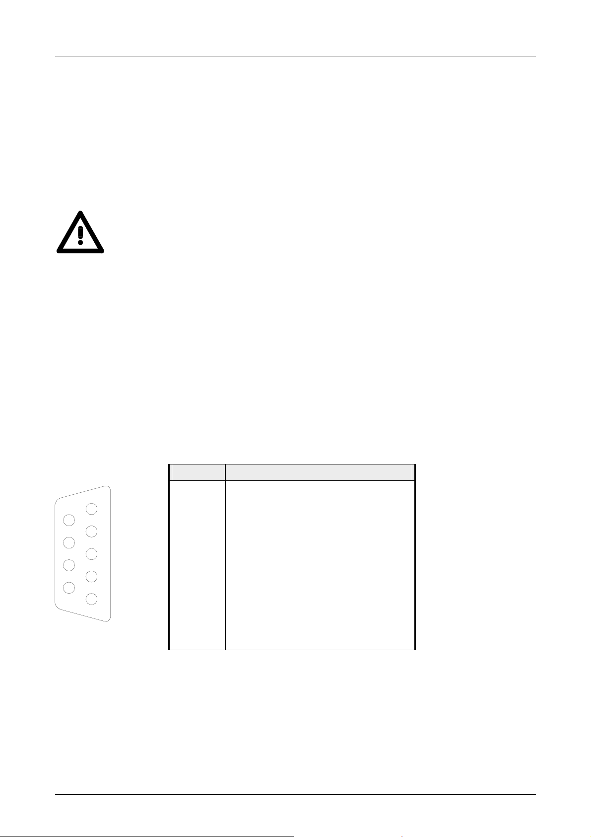
Chapter 2 Hardware description Manual VIPA CPU 21x
Battery backup for
clock and RAM
2
I interface
MP
5
9
4
8
3
7
2
6
1
A rechargeable battery is installed on every CPU 21x to safeguard the
contents of the RAM when power is removed. This battery is also used to
buffer the inter nal clock.
The rechargeable bat tery is maintained by a charging circuit that receives
its power from the internal power supply and that maintain the clock and
RAM for a max. period of 30 days.
Attention!
The CPU will operate only if the battery is healthy.
The CPU will STOP when t he batter y is faulty. In t his case the CPU should
be checked. Please contact VIPA!
The MPI unit provides the link for the dat a transfer between the CPU and
the PC. Via bus communication you are able to exchange programs and
data between different CPUs that ar e linked over MPI.
For a serial exchange between the partners you normally need a special
MPI-converter. But now you are also able to use the VIPA "Green Cable"
(Order-No. VIPA 950-0KB00), which allows you to establish a serial peerto-peer connection over the MPI interface.
Please regard the notes about the "G r een Cable" in chapter "Principles"!
2
The pin assignment of the MP
I jack is as follows:
9pin jack
Pin Assignment
1 reserved (must not be connect ed)
See Hints for the deployment of the
MPI interface in chapter "Priciples".
2 M24V
3 RxD/TxD-P (Line B)
4 RTS
5 M5V
6 P5V
7 P24V
8 RxD/TxD-N (Line A)
9 n.c.
2-14 HB103E - Rev. 05/45
Page 45
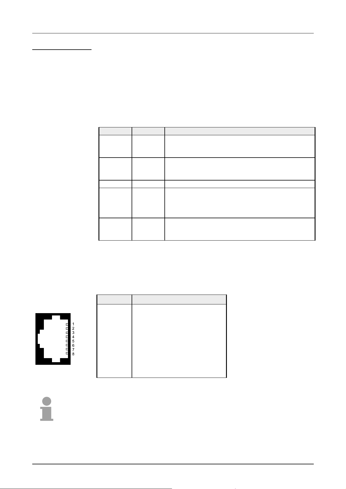
Manual VIPA CPU 21x Chapter 2 Hardware description
CPU 21x-2BT10
LEDs
In addition to the components described in the sect ion on the CPU 21x the
CPU 21x-2BT10 module is provided with further LEDs and an Ethernet
interface located at the left-hand side of the module.
The LEDs are located on the left -hand side of the front panel and indicat e
communication activities.
The table below shows the color and the meaning of these LEDs.
Name Color Description
RN green CP RUN
On: CP project is loaded
Off: CP is reset ( no pr oject)
ST yellow CP STOP
On: CP status is reset
Off: CP Proj ect is transferred
IF red On: Internal CP error
L/A green Link/Activity:
On: physically connected to Ethernet
Off: no physical connection to Ether net
Blinks: Ethernet activity
S green Transfer speed:
On: 100MBit
Off: 10MBit
Ethernet interface
An RJ45 jack provides the interface t o the twisted pair cable, required for
Ethernet. The pin assignment of this jack is as follows:
8pin RJ45 jack:
Pin Assignment
1 Transmit +
2 Transmit 3 Receive +
4 5 6 Receive 7 8 -
Note!
For more detailed information on twisted pair networks refer to chapter
"Deployment of the CPU 21x-2BT10".
HB103E - Rev. 05/45 2-15
Page 46
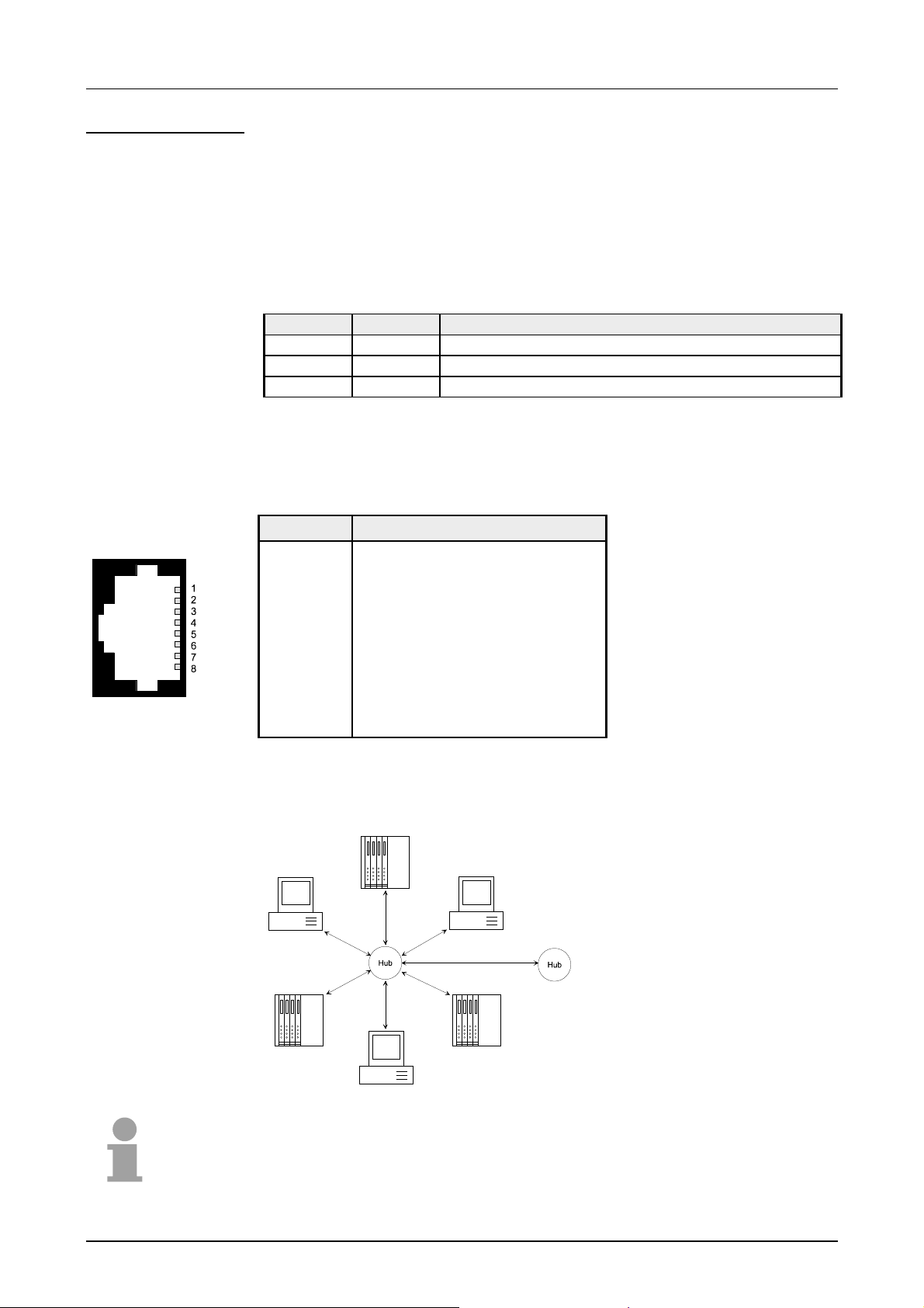
Chapter 2 Hardware description Manual VIPA CPU 21x
CPU 21x-2BT02
LEDs
Ethernet interface
In addition to the components described in the sect ion on the CPU 21x the
CPU 21x-2BT02 module is provided with further LEDs and an Ethernet
interface located at the left-hand side of the module.
The LEDs are located on the left -hand side of the front panel and indicat e
communication activities.
The table below shows the color and the meaning of these LEDs.
Name Color Description
PW green Indicates CPU power on
TxD green Transmit data
RxD green Receive data
An RJ45 jack provides the interface t o the twisted pair cable, required for
Ethernet. The pin assignment of this jack is as follows:
8pin RJ45 jack:
Pin Assignment
1 Transmit +
2 Transmit 3 Receive +
4 5 6 Receive 7 8 -
Star topology
A twisted pair network can only have a star topology. For this purpose a
hub is required as the central node:
Note!
For more detailed information on twisted pair networks refer to chapter
2-16 HB103E - Rev. 05/45
"Deployment of the CPU 21x-2BT02".
Page 47

Manual VIPA CPU 21x Chapter 2 Hardware description
CPU 21xDPM
LEDs
In addition to the components described in the sect ion on the CPU 21x the
CPU 21xDPM module is provided with 4 more LEDs and a Profibus
interface.
The LEDs are located in t he left half of the fr ont panel and they are used
for diagnostic purposes. The following table shows the color and the
significance of these LEDs.
Name Color Description
RN green DP-Master-RUN
On: Master status is RUN. The slaves are being
accessed and the outputs are 0 ("clear" state) .
On with DE: Master status is "operate". and is
communicating with the slaves.
IF red Initialization error
On: Error in Prof ibus configuration
DE yellow DE (Data exchange)
On: Indicates Profibus comm unicat ion act ivity.
ER red Error
On: Slave has failed
Profibus interface
5
9
4
8
3
7
2
6
1
The CPU 21xDPM is connected to the Profibus system by means of a 9pin
jack. The pin assignment of this interface is as shown:
9pin Profibus D-type jack:
Pin Assignment
1 Shield
2 n.c.
3 RxD/T xD-P ( L ine B)
4 RTS
5 M5V
6 P5V
7 n.c.
8 RxD/T xD-N (Line A)
9 n.c.
Note!
Refer to the chapter "Deployment of the CPU 21xDPM" for details on the
Profibus master.
HB103E - Rev. 05/45 2-17
Page 48

Chapter 2 Hardware description Manual VIPA CPU 21x
CPU 21xDP
LEDs
In addition to the components described in the sect ion on the CPU 21x the
CPU 21xDP module is provided with 3 more LEDs and a Profibus interface.
The LEDs are located in t he left half of the fr ont panel and they are used
for diagnostic purposes. The following table shows the color and the
significance of these LEDs.
Name Color Description
ER red Error
On: Error in Profibus par t detected respectively
CPU has been stopped.
Flashing (2Hz): Initialization error
Flashing (10Hz): Supply voltage < DC18V
Flashing alternately with RD: Conf iguration error
(error at Master configur at ion)
Flashing simultaneously with RD: Error in
parameterization
RD green Ready
On: Data transfer via back plane bus
Flashing: Self-test result is positive (READY) and
successful initialization
DE green DE (Data exchange)
On: Indicates an active Profibus communicat ion.
Profibus interface
5
9
4
8
3
7
2
6
1
The CPU 21xDP is connected to the Profibus system by means of a 9pin
jack. The pin assignment of this interface is as shown:
9pin Profibus D-type jack:
Pin Assignment
1 Shield
2 n.c.
3 RxD/T xD-P ( L ine B)
4 RTS
5 M5V
6 P5V
7 n.c.
8 RxD/T xD-N (Line A)
9 n.c.
Note!
Refer to the chapter "Deployment of the CPU 21xDP" for details on the
Profibus.
2-18 HB103E - Rev. 05/45
Page 49

Manual VIPA CPU 21x Chapter 2 Hardware description
CPU 21xCAN
LEDs
In addition to the components described in the sect ion on the CPU 21x the
CPU 21xCAN module is provided with 4 more LEDs and a CAN interface.
The LEDs are located in t he left half of the fr ont panel and they are used
for diagnostic purposes. The following table shows the color and the
significance of these LEDs.
Name Color Description
RN green CAN master RUN
ON: CAN master state is RUN
OFF: CAN master state is STOP
ER red Error
ON: During initialization and at slave failur e
OFF: All slaves are in the state "operational"
BA yellow BA (Bus active)
On: CAN bus communication respectively state
"operational"
Blinking (1Hz): State "pre-operational".
IF red Initialization
ON: Initialization error at wrong parameterization.
Off: I nitialization is OK.
CAN interface
1
6
2
7
3
8
4
9
5
Note!
If all LEDs are blinking with 1Hz, the CAN ma ster awaits valid parameters
from the CPU. If the CAN master is not supplied with parameters by the
CPU his LEDs get off after 5s.
The CPU 21xCAN is connected to the CAN system by means of a 9pin
plug. The pin assignment of this interface is as shown:
9pin CAN D-type plug:
Pin Assignment
1 reserved
2 CAN low
3 CAN Ground
4 reserved
5 Screen
6 Ground 24V
7 CAN high
8 reserved
9 +DC 24V
Note!
More details on the CAN master see chapter "Deployment CPU 21xCAN"!
HB103E - Rev. 05/45 2-19
Page 50

Chapter 2 Hardware description Manual VIPA CPU 21x
CPU 11xSER-1
LEDs
RS232C interface
1
6
2
7
3
8
4
9
5
Additional to the components described before, the CPU 21x with order no.
21x-2BS12 has an RS232C interface and the CPU 21x with order no.
21x-2BS32 an RS485 interface.
The LEDs are located in t he left half of the fr ont panel and they are used
for diagnostic purposes. The following table shows the color and the
significance of these LEDs.
Name Color Description
Rx g r een Interface receive data
Tx green Interface t r ansm it data
Via 9pin jack, you may establish a serial RS232C point-to-point connect ion.
The pin assignment of this interface is as shown:
9pin plug
(CPU 21x-2BS12)
Pin Assignment
1 CD2 RxD
3 TxD
4 DTR5 GND
6 DSR7 RTS8 CTS9 RI-
RS485 interface
Via 9pin slot, you may establish a serial RS485 bus connection. The pin
assignment of this interface is as shown:
9pin jack
(CPU 21x-2BS32)
Pin Assignment
1 n.c.
5
9
4
8
3
7
2
6
1
2 n.c.
3 RxD/T xD-P ( L ine B)
4 RTS
5 M5V
6 P5V
7 n.c.
8 RxD/T xD-N (Line A)
9 n.c.
2-20 HB103E - Rev. 05/45
Page 51

Manual VIPA CPU 21x Chapter 2 Hardware description
CPU 21xSER-2
LEDs
RS232C
interface
COM1, COM2
1
6
2
7
3
8
4
9
5
In addition to the components described in the sect ion on the CPU 21x the
CPU 21xSER-2 module is provided with more LEDs and two serial RS232C
interfaces.
The LEDs are located in t he left half of the fr ont panel and they are used
for diagnostic purposes. The following table shows the color and the
significance of these LEDs.
Name Color Description
RN green Communication processor runs
ER1 red Error Interface 1
Rx1 green Interface 1 receive data
Tx1 green Interface 1 transmit data
ER2 red Error Interface 2
Rx2 green Interface 2 receive data
Tx2 green Interface 2 transmit data
The CPU 21xSER-2 has got a communication processor with 2 RS232C
interfaces. The pin assignment of the interfaces is as follows:
9pin jack
Pin Assignment
1 CD2 RxD
3 TxD
4 DTR5 GND
6 DSR7 RTS8 CTS9 RI-
HB103E - Rev. 05/45 2-21
Page 52
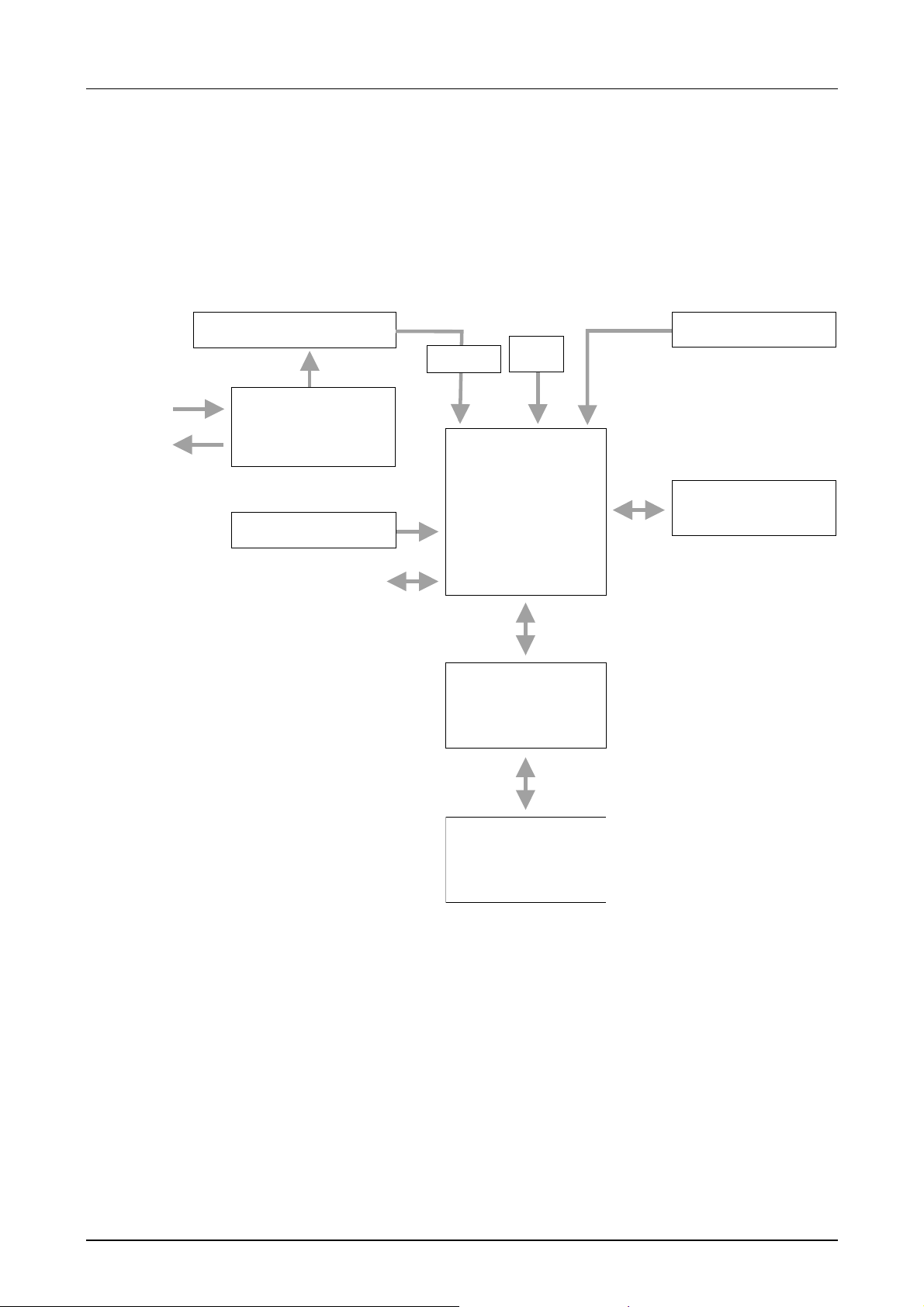
Chapter 2 Hardware description Manual VIPA CPU 21x
Block diagram
The following block diag ram shows the basic hardware construction of the
CPU 21x modules:
DC 24V
PW
Voltage monitor
Power
supply
Clock
PU/AG
RESET
interface circuitry
Pulse
Processor
System 200V
RUN/STOP/MR
Memory-Card
System 200V
backplane bus
2-22 HB103E - Rev. 05/45
Page 53

Manual VIPA CPU 21x Chapter 2 Hardware description
Technical data
CPU 21x
General
Electrical data VIPA 214-1BC02, VIPA 214-1BA02 ... VIPA 216-1BA02
Power supply DC 24V (20.4 ... 28.8V)
Current consumption max. 1.5A
Dissipation power max. 3.5W
Status indicators (LEDs) by means of LEDs located on the front
Connections / interfaces MP2I interface for data communication
Clock, memory/clock backup yes / Lithium accumulator, 30 days backup
Output current to backplane bus max. 3A
Bit memory 8192 Bit (M0.0…M255.7)
Timer 256 (T0...T255)
Counters 256 (Z0 ... Z255)
Number of Blocks FB
FC
DB
Total addressing space input / output 1024/1024Byte, each 128 Byte for process image (PA)
Process image Inputs 1024Bit (I0.0...I127.7)
Process image Outputs 1024Bit (O0.0...O127.7)
Combination with peripheral modules
max. no. of modules 32
max. digital I/O 32
max. analog I/O 16
Addressable inputs, outputs 1024 (digital), 128/128 (analog)
Dimensions and weight
Dimensions (WxHxD) in mm 25.4x76x80
Weight 80g
1024 (FB0...FB1023)
1024 (FC0...FC1023)
2047 (DB1...DB2047)
Module specific
CPU 214C CPU 214 CPU 215 CPU 216
Work memory 32kByte 48kByte 96kByte 128kByte
Load memory 40kByte 80kByte 144kByte 192kByte
Cycle time bit operations
Cycle time word operations
Order-No.: 214-1BC02 214-1BA02 215-1BA02 216-1BA02
HB103E - Rev. 05/45 2-23
0.18µs 0.18µs 0.18µs 0.18µs
0.78µs 0.78µs 0.78µs 0.78µs
Page 54

Chapter 2 Hardware description Manual VIPA CPU 21x
CPU 21x-2BT10
Electrical data VIPA 214-2BT10 ... VIPA 216-2BT10
Power supply DC 24V (20.4 ... 28.8V)
Current consumption max. 1.5A
Dissipation power max. 6W
Potential separation
Status indicator (LEDs) like CPU 21x additionally with LEDs for the Ethernet section
Connections/interfaces like CPU 21x additionally with RJ45 jack ( Et hernet)
Ethernet interface CP 243
Connector RJ45
Network topology Star topology
Medium Twisted pair
Transfer rate 10/100Mbit
Overall length max. 100m per segment
PG/OP channel 8 (32 with CP firmware version 1.7.4 and up)
Configurable connections: 16
Dimensions and weight
Dimensions (WxHxD) in mm 50.8x76x80
Weight 150g
≥ 500V AC to Ethernet
CPU 21x-2BT02
Electrical data VIPA 214-2BT02 ... VIPA 216-2BT02
Power supply DC 24V (20.4 ... 28.8V)
Current consumption max. 1.5A
Dissipation power max. 6W
Potential separation
Status indicator (LEDs) like CPU 21x additionally with LEDs for the Ethernet section
Connections/interfaces like CPU 21x additionally with RJ45 jack ( Et hernet)
Ethernet interface CP 243
Connector RJ45
Network topology Star topology
Medium Twisted pair
Transfer rate 10Mbit
Overall length max. 100m per segment
PG/OP channel Configurable connections: 32
Dimensions and weight
Dimensions (WxHxD) in mm 50.8x76x80
Weight 150g
≥ 500V AC to Ethernet
2-24 HB103E - Rev. 05/45
Page 55

Manual VIPA CPU 21x Chapter 2 Hardware description
CPU 21xDPM
Electrical Data VIPA 214-2BM02 ... VIPA 216-2BM02
Power supply DC 24V (20.4 ... 28.8V)
Current consumption max. 1.5A
Dissipation power max. 5W
Potential separation
Status monitoring (LEDs) like CPU 21x additionally with LEDs for the Profibus section
Adapters/interfaces like CPU 21x additionally with 9pin D-type jack (Profibus)
Profibus interface
Connector 9pin D-type jack
Network topology Linear bus, active bus termination at both ends
Medium Screened and drilled twisted pair cable. Depending on
Transfer rate 9.6kBaud up to 12MBaud
Overall length 100m at 12 MBaud without repeater, up to 1000m with repeater
max. no. of stations 32 stations on every segment without repeater. Expandable to
Combination with
peripheral modules
max. number of slaves 125
max. number of input bytes 1024
max. number of output bytes 1024
Dimensions and Weight
Dimensions (WxHxD) in mm 50.8x76x80
Weight 150g
≥ 500V AC to fieldbus
environment screening may be omitted.
126 stations with repeater.
CPU 21xDP
Electrical data VIPA 214-2BP02 ... VIPA 216-2BP02
Power supply DC 24V (20.4 ... 28.8V)
Current consumption max. 1.5A
Dissipation power max. 5W
Potential separation
Status indicator (LEDs) like CPU 21x additionally with LEDs for the Profibus sect ion
Adapters/interfaces like CPU 21x additionally with 9pin D-type jack (Profibus)
Profibus interface
Connector 9pin D-type jack
Network topology Linear bus, active bus termination at both ends
Medium Screened and drilled twisted pair cable. Depending on
Transfer rate 9.6kBaud up to 12MBaud
Overall length 100m at 12 MBaud without repeater, up to 1000m with repeater
max. no. of stations 32 stations on every segment without repeater.
Dimensions and weight
Dimensions (WxHxD) in mm 50.8x76x80
Weight 150g
≥ 500V AC to fieldbus
environment screening may be omitted.
Expandable to 126 stations with repeater.
HB103E - Rev. 05/45 2-25
Page 56

Chapter 2 Hardware description Manual VIPA CPU 21x
CPU 21xCAN
Electrical Data VIPA 214-2CM02 ... VIPA 216-2CM02
Power supply DC 24V (20.4 ... 28.8V)
Current consumption max. 1.5A
Dissipation power max. 5W
Potential separation
Status monitoring (LEDs) like CPU 21x additionally with LEDs for the CAN section
Adapters/interfaces like CPU 21x additionally with 9pin D-type jack (CAN)
CAN interface
Connector 9pin D-type jack
Network topology Linear bus, active bus termination at both ends
Medium Screened and drilled twisted pair cable. Depending on
Transfer rate 10kBaud up to 1MBaud
Overall length without repeater 1000m at 50kBaud
max. no. of stations 126 stations
Combination with
peripheral modules
max. number of slaves 125
max. number of TxPDOs 40
max. number of RxPDOs 40
max. number of input bytes 384
max. number of output bytes 384
Dimensions and Weight
Dimensions (WxHxD) in mm 50.8x76x80
Weight 150g
≥ 500V AC to fieldbus
environment screening may be omitted.
2-26 HB103E - Rev. 05/45
Page 57

Manual VIPA CPU 21x Chapter 2 Hardware description
CPU 21xSER-1
Module specific VIPA 214-2BS12...216-2BS12 VIPA 214-2BS32...216-2BS32
Power supply DC 24V (20.4 ... 28.8)
Current consumption max. 1.5A
Dissipation power max. 5W
Potential separation
Status indicator (LEDs) like CPU 21x
RS232C interface integrat ed yes RS485 interface integrat ed - yes
Dimensions and weight
Dimensions (WxHxD) in mm 50.8x76x80
Weight 150g
CPU 21xSER-2
Electrical data VIPA 214-2BS02 ... VIPA 216-2BS02
Power supply DC 24V (20.4 ... 28.8V)
Current consumption max. 1.5A
Dissipation power max. 5W
Potential separation Status indicator (LEDs) like CPU 21x additionally with LEDs for serial communication
Adapters/interfaces like CPU 21x additionally with
Interfaces
COM 1, COM 2 2 integrated RS232C interfaces
Dimensions and weight
Dimensions (WxHxD) in mm 50.8x76x80
Weight 150g
≥ 500V AC to serial interface
2x 9pin D-type jack (serial communication)
HB103E - Rev. 05/45 2-27
Page 58

Chapter 2 Hardware description Manual VIPA CPU 21x
2-28 HB103E - Rev. 05/45
Page 59

Manual VIPA CPU 21x Chapt e r 3 Depl oyment CPU 21x
Chapter 3 Deployment CPU 21x
Outline
Contents
This chapter describes the deployment of the CPU 21x together with the
peripheral modules of the System 200V.
Besides commissioning and start-up behavior you will find here also a
description of the project engineering, parameterization, operating modes
and test functions.
This information also basically applies to the deployment of the CPU 21x
with integrated communication part.
The following section contains a description of :
• Assembly and commissioning
• Principle of address allocation
• Project engineering and param eterization
• Deployment of MPI and MMC
• Operating modes and overall reset and f ir m ware update
• Usage of test funct ions
Topic Page
Chapter 3
Assembly..............................................................................................3-2
Start-up behavior..................................................................................3-3
Address allocation................................................................................3-4
Project engineering..............................................................................3-6
Configuration of the CPU parameters ..................................................3-9
Project transfer...................................................................................3-11
Operating modes................................................................................3-14
Overall Reset .....................................................................................3-15
Firmware update................................................................................3-17
Using test functions for the control and monitoring of variables..........3-20
Deployment CPU 21x......................................................3-1
Note!
This informat ion is valid for all the CPUs described in this m anual since the
HB103E - Rev. 05/45 3-1
backplane bus communication between the CPU and the peripheral
modules is the same for all models of this CPU!
Page 60
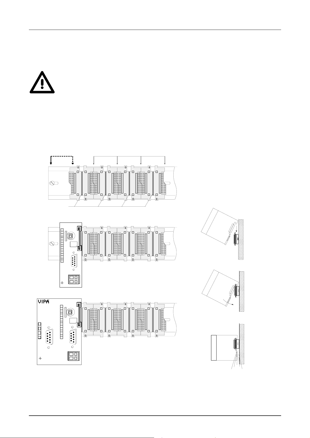
Chapter 3 Deployment CPU 21x Manual VIPA CPU 21x
Assembly
Attention!
It is mandatory to tur n off the power supply before you insert or rem ove any
CPU
1
2
modules!
Please note that the CPU may only be installed into plug- in location 1 or 2
(see figure below).
3
[1] CPU, double width
[2] CPU, single width
[3] Peripheral modules
[4] Guiding bars
ER
RD
D
DE
P
X2
34
VIPA 216-2BP02
4
CPU 216
R
S
MMC
PW
SF
FC
MC
DC
+
24V
-
X2
34
VIPA 216 -2 BA01
CPU 216DP
R
S
MMC
PW
SF
FC
MC
DC
+
24V
-
RN
ST
MR
➡➡
M
2
P
I
X1
1
2
RN
ST
MR
M
2
P
I
X1
1
2
Clack
For details on the assembly of System 200V modules please refer to the
System 200V manual (Order-No.: VI PA HB97).
3-2 HB103E - Rev. 05/45
Page 61
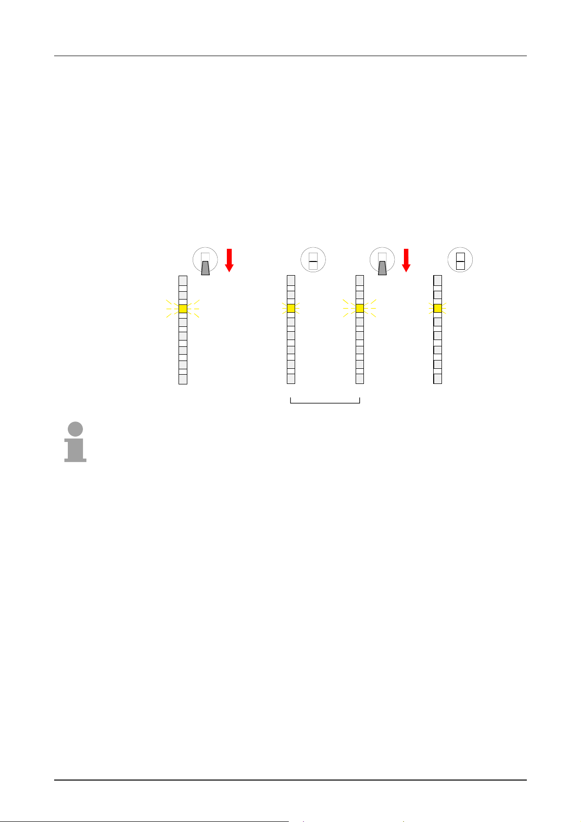
Manual VIPA CPU 21x Chapt e r 3 Depl oyment CPU 21x
Start-up behavior
Turn on
power supply
OVERALL_RESET
After turning on t he power supply, the CPU switches to the operating mode
that is fixed by the operating mode lever at t he CPU.
Now you may transfer your project from your projecting tool into the CPU
via MPI resp. plug-in a MMC containing your project and request an
OVERALL_RESET.
The following picture shows the approach:
RN
ST
MR
3Sec.
R
S
PW
SF
FC
MC
RN
ST
MR
R
PW
SF
FC
MC
S
3 Sec.
RN
ST
MR
PW
SF
FC
MC
RN
ST
MR
R
S
R
S
PW
SF
FC
MC
Note!
The transfer of the user application from the MMC into the CPU takes
always place after an OVERALL RESET!
Start-up after
delivery
Start-up with valid
data on the CPU
Start-up with
empty battery
After delivery the CPU is totally clear.
After a STOP→RUN transition, the CPU switches to RUN without
application.
The CPU switches to RUN with the application located in the battery
buffered RAM.
The battery is loaded directly via the integrated power supply and provides
a buffer for up to 30 days. If this time is exceeded, the battery may be
totally discharged and the battery buffered RAM is erased.
In this state the CPU starts an overall_reset. If a MMC is plugged in, the
program of the MMC is transferr ed into the RAM.
Depending on the selected oper ating mode the CPU switches to RUN resp.
stays in STOP.
This procedure is fixed in the diagnostic buf fer with this entry: "Automatic
start OVERALL_RESET (unbuffered POWER-ON)".
HB103E - Rev. 05/45 3-3
Page 62
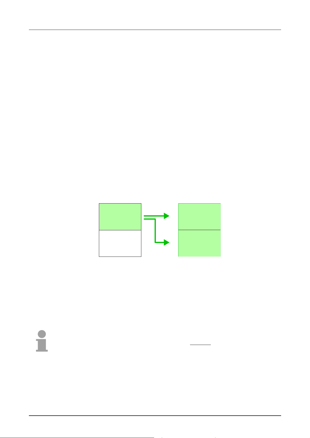
Chapter 3 Deployment CPU 21x Manual VIPA CPU 21x
Address allocation
Automatic
addressing
Signaling states in
the process image
To provide specific addressing of the installed peripheral modules, certain
addresses must be allocated in the CPU.
The CPU contains a peripheral area (addresses 0 ... 1023) and a process
image of the inputs and the outputs (for both each address 0 ... 127).
When the CPU is initialized it automatically assigns peripher al addresses to
the digital input/output modules st ar ting from 0.
If there is no hardware projecting, analog modules are allocated to even
addresses starting from addr ess 128.
The signaling states of the lower addresses (0 ... 127) are additionally
saved in a special memory area called the process image.
The process image is divided into two parts:
• process image of the inputs (PI I )
• process image of the outputs ( PI Q )
Peripheral area
0
.
.
Digital modules
.
127
128
.
Analog modules
.
.
1023
Process image
0
.
.
.
127
0
.
.
.
127
Inputs
Outputs
PII
PIQ
The process image is updated automatically when a cycle has been
completed.
Read/write access
You may access the modules by means of r ead or write operations on the
peripheral bytes or on the process image.
Note!
modules by means of read
Please remember that you may access differ ent
and write operations on the same address.
The addressing ranges of digital and analog modules are different when
they are addressed automatically.
Digital modules: 0 ... 127
Analog modules: 128 ... 1023
3-4 HB103E - Rev. 05/45
Page 63
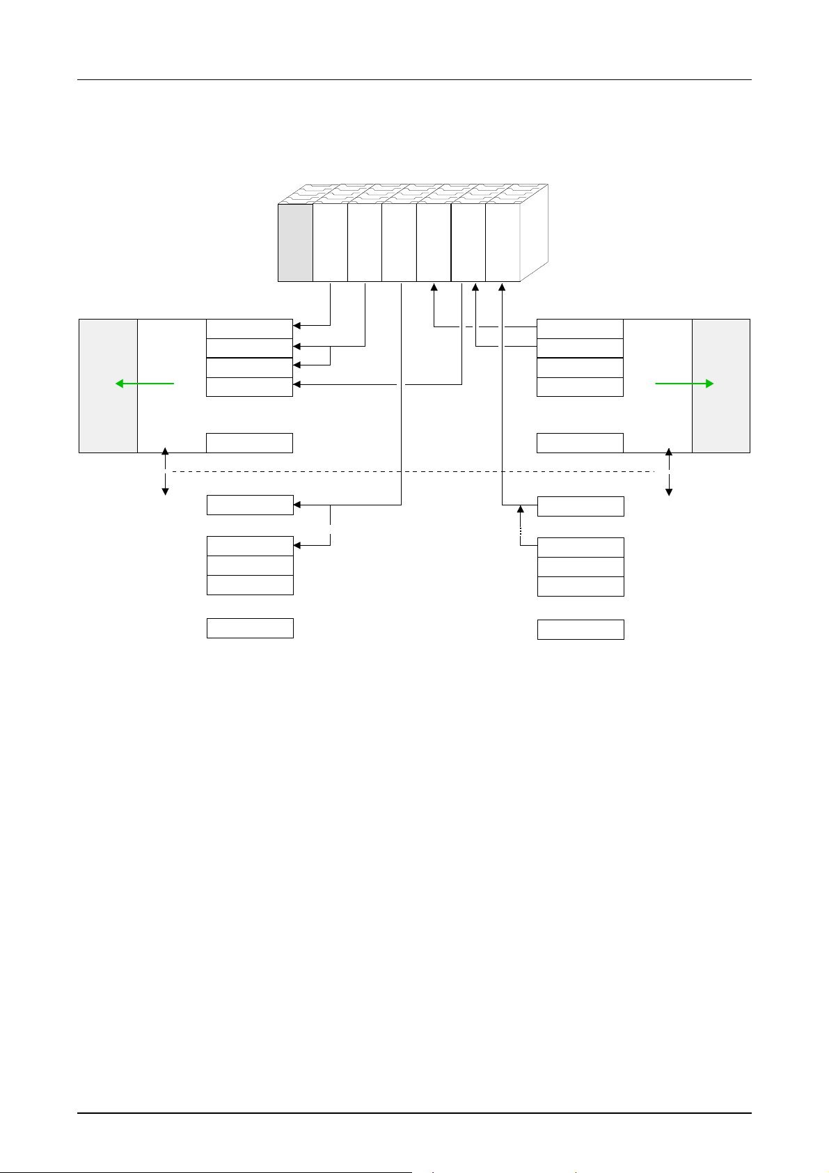
Manual VIPA CPU 21x Chapt e r 3 Depl oyment CPU 21x
Example for automatic address
allocation
PII
rel. Addr.
0
1
2
3
127
digital
analog
128
135
136
137
1023
Peripheral area
Input byte 0
Input byte 1
Input byte 2
Input byte 3
.
.
.
Input byte 127
Input byte 0
.
.
.
Input byte 7
Input byte 8
Input byte 9
.
.
.
Input byte 1023
The following figure illust r at es the automatic allocation of addresses:
.
.
.
.
.
.
.
.
.
Plug-in location: 1 2 3 4 5 6
DO 8xDC24V
DI 8xDC24V
CPU 21x
.
.
.
AI 4x12Bit
DI 16xDC24V
DIO 8xDC24V
AO 4x12Bit
Peripheral area
Output byte 0
Output byte 1
Output byte 2
Output byte 3
.
.
.
Output byte 127
Output byte 0
.
.
.
Output byte 7
Output byte 8
Output byte 9
.
.
.
Output byte 1023
rel. Addr
127
128
135
136
137
1023
0
1
2
3
.
.
.
digital
analog
.
.
.
.
.
.
PIQ
Modifying allocated
addresses by
configuration
You may change the allocated addresses at any time by means of the
Siemens SIMATIC Manager. In this way you may also change the addresses of analog modules to the range covered by the process image (0...127)
and address digital modules above 127.
The following pages describe the req uired preparations and the procedure
for this type of configuration.
HB103E - Rev. 05/45 3-5
Page 64

Chapter 3 Deployment CPU 21x Manual VIPA CPU 21x
Project engineering
General
Fast introduction
The following informat ion always refers to modules t hat have been installed
on the same bus adjacent to the CPU.
In order to address the installed peripheral modules individually, specific
addresses in the CPU have to be assigned to them.
The allocation of addresses and the config uration of the installed modules
is a function of the Siemens SIMATIC Manager where the modules appear
as a virtual Profibus system. For the Profibus interface is software
standardized, we are able to guarantee the complete functionality of the
System 200V together with the Siemens SIMATIC Manager by including a
GSD-file (german: GeräteStammDatei = GSD-file).
The project is transf erred serial to the CPU via the MPI interface or by use
of a MMC.
For the employment of the CPU 21x from VIPA using the Siemens
SIMATIC Manager the inclusion of the System 200V via the vipa GSD file
in the hardware catalog is required.
To be compatible with the Siemens SIMATIC Manager you have to execute
the following steps:
• Start the hardware conf igurator f rom Siemens and include vipa_21x.gsd
from VIPA.
• Configure CPU 315-2DP (315-2AF03 0AB00 V1.2) from Siemens and
create a new Profibus subnet.
• Attach the System "VIPA_CPU21x" to the subnet with ProfibusAddress 1, to be found at the hardware catalog at PROFIBUS DP >
Additional field devices > IO > VIPA_System_200V.
st
• Place always at the 1
from the hardware catalog.
• Include afterwards your System 200V modules in the location sequence.
• Save and transfer you project.
slot the corresponding CPU 21x, by taking it
Requirements
3-6 HB103E - Rev. 05/45
The following conditions must be f ulfilled for project engineering:
• The Siemens SIMATIC Manager is installed at PC respectively PU
• The GSD files have been included in Siemens hardware configurator
• Serial connection to the CPU (e.g. "Green Cable" from VIPA)
Note!
The configuration of the CPU requires a thorough knowledge of the
Siemens SIMATIC Manager and the hardware configurat or !
Page 65
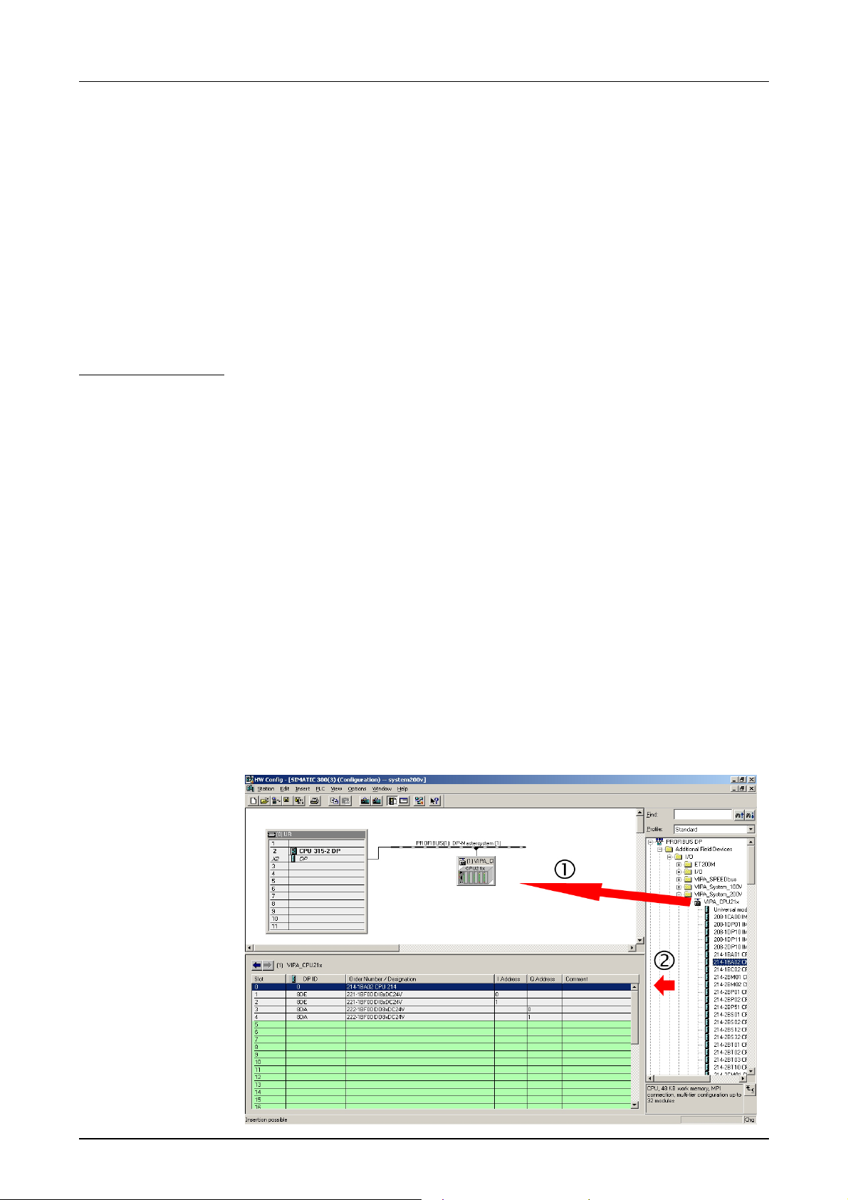
Manual VIPA CPU 21x Chapt e r 3 Depl oyment CPU 21x
Including the
GSD- file
Project engineering
CPU 21x
Project engineering
System 200V
modules
• Go to www.vipa.de > Service > Download > GSD- und EDS- Files >
Profibus and download the file Cx000023_Vxxx.
• Extract the file to your work directory. The vipa_21x.gsd (german)
respectively vipa_21x.gse (english) can be found at the directory
VIPA_System_200V.
• Start the Siemens hardware configur ator and close every project.
• Go to Options > Install new GSD file
• Navigate to the directory System_200V and choose the corresponding
file vipa_cpu21x.gsd (german) or vipa_cpu21x.gse ( english)
Now the modules of the VIPA System 200V are integrated in the hardware
catalog at Profibus-DP \ Additional field devices \ I/O \ VIPA_System_200V.
• Start the Siemens hardware configur ator with a new project and insert a
profil rail from t he hardware catalog.
• Place at the 1st possible slot the CPU 315-2DP (6ES7 315-2AF03 V1.2)
from Siemens.
• If your CPU 21x provides a DP master, you may now connect it to
Profibus and include your DP slaves.
The System 200V modules have to be configured after project engineering
of the CPU 21x as described below:
• Create a Profibus subnet (if not yet available).
• Attach the System "VIPA_CPU21x" to the subnet. The respective
entries are located in the hardware catalog under PROFIBUS DP >
Additional Field Devices > IO > VIPA_System_200V. Assign Profibus
address 1 to this slave.
st
• Place the VIPA CPU 21x that you want to deploy at the 1
plug-in
location of the configur ator by taking if from the hardware catalog.
• Include your System 200V modules in the location sequence behind it.
• Save your project.
HB103E - Rev. 05/45 3-7
Page 66
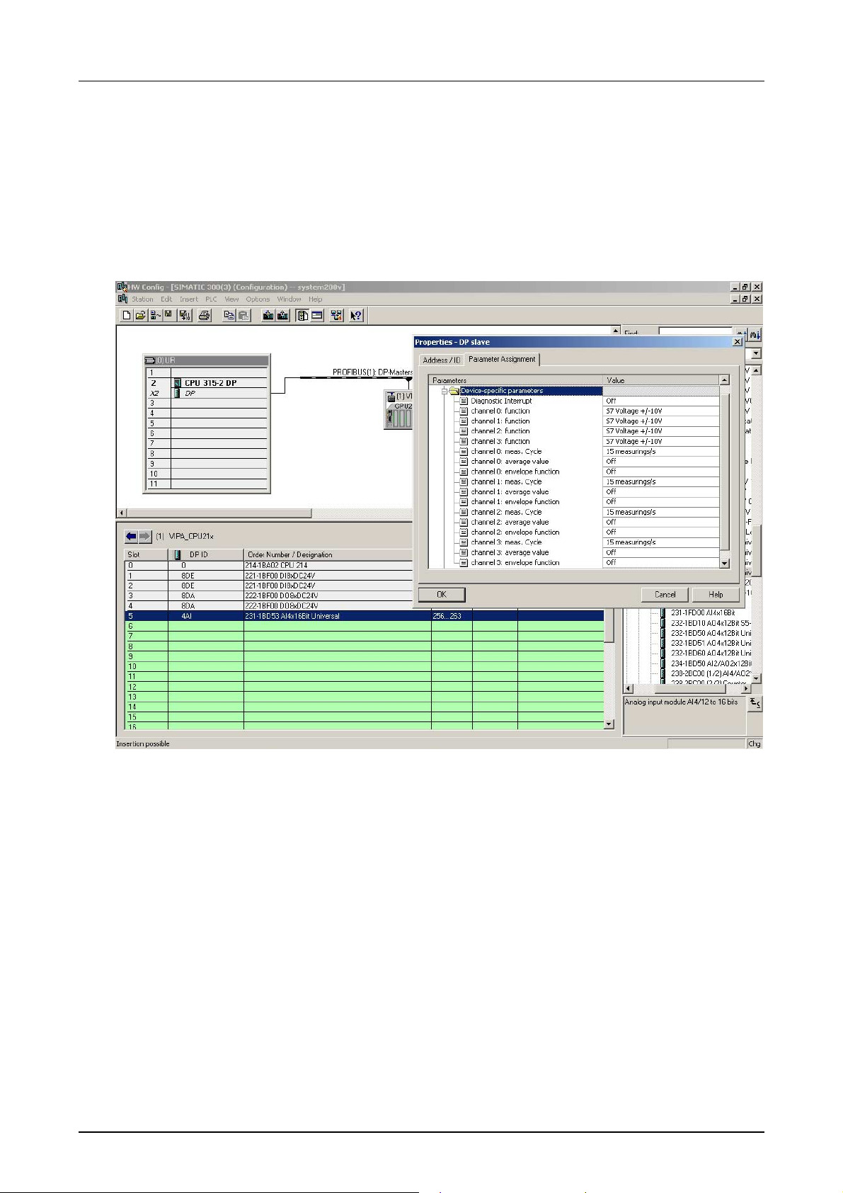
Chapter 3 Deployment CPU 21x Manual VIPA CPU 21x
Parameterization
System 200V
modules
System 200V modules may be supplied with up to 16Byte of configuration
data from t he CPU. T he use of the Siem ens SIMATIC Manager pr ovide the
option to supply parameters to the configurable System 200V modules at
any time.
For this purpose you have to double-click the respective module in the
plug-in diagram.
The following figure shows the configuration of a analog input module:
Transferring the
project
Data is transferred between the CPU and the PC via MPI. If your PG has
no MPI functionality you may use the VIPA "Green Cable" to send the data
serial by a peer-to-peer connection. The VIPA "Green Cable" has the
OrderNo. VIPA 950-0KB00 and may only be used at MP
2
I interfaces of
VIPA CPUs!
Please regard the notes about the "G r een Cable" in chapter 1!
• Connect your PG to the CPU
• Transfer the proj ect into the CPU by means of PLC > Load into module
in your project configurat ion t ool.
• Install an MMC and transfer the application program to the MMC by
clicking on PLC > Copy RAM to ROM.
• During the write oper ation the "MC"-LED of the CPU blinks. For internal
reasons the message signalizing completion of the write operation
arrives too soon. The write operation is only complete when the LED
gets off.
3-8 HB103E - Rev. 05/45
Page 67
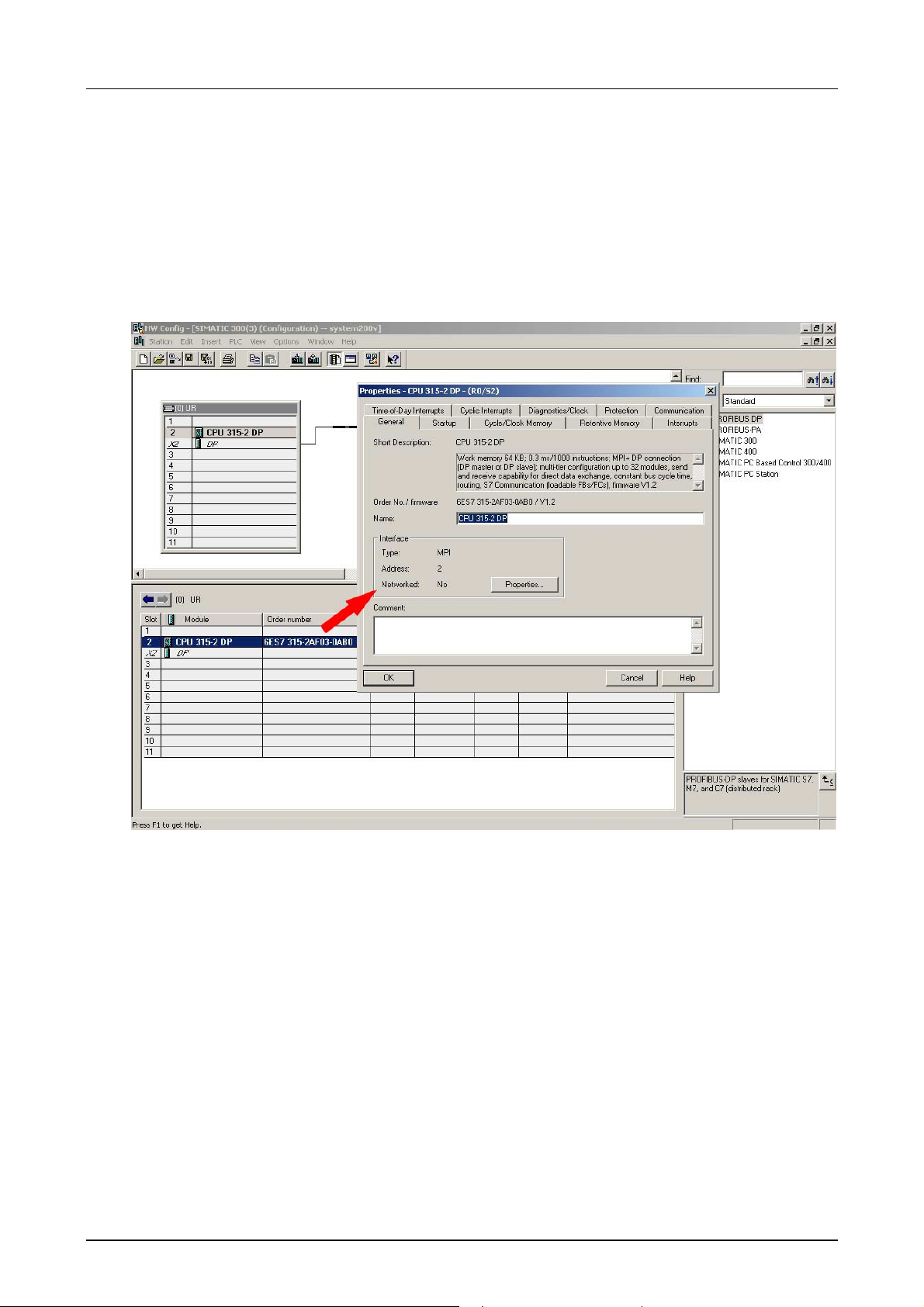
Manual VIPA CPU 21x Chapt e r 3 Depl oyment CPU 21x
Configuration of the CPU parameters
Outline
Except of the Profibus parameters of the CPU 21xDP the CPU
parameterization takes place in the parameter dialog of the CPU 315-
2DP. The parameterization of t he Prof ibus sect ion of the CPU 21xDP takes
place via the parameterization dialog of the CPU 21xDP.
Parameterization
CPU 21x under
CPU 315-2DP
HB103E - Rev. 05/45 3-9
Per double-click on the CPU 315-2DP you reach the parameterization window of your CPU 21x. Via the different registers you may access all
parameters of the CPU 315-2DP. The parameters are those of the
CPU 21x from VIPA.
Please regard, that at this t im e not all the parameters are supported.
Page 68

Chapter 3 Deployment CPU 21x Manual VIPA CPU 21x
Supported
parameters
The CPU 21x doesn't use all the parameters that may be defined in the
Siemens SIMATIC Manager.
The following parameters are cur r ently employed by the CPU:
General:
MPI address of the CPU
Baud rate (19.2kBaud, 187 kBaud)
maximum MPI address
Startup:
Startup when expected/actual
configuration dif fer
"Finished" message by modules
Transfer of par am et ers to modules
Retentive memory:
Number of Memory bytes
starting with MB0
Number of S7 Timers star t ing
with T0
Number of S7Counters starting
Time-of-Day Interrupts:
OB10: active
execution
start date
time-of-day
Cyclic Interrupts:
OB35: execution
Cycle Clock Memory:
Scan Cycle monitoring time
Scan Cycle load from
communication
OB85: Call up at I/O access error
Clock bit memory with memory
byte no.
with C0
Protection:
Level of protection
removable with password
Parameterization
Profibus section
of CPU 21xDP
You may reach the parameterization window for the Profibus sect ion of the
CPU 21x by double-clicking on the added System 200V-CPU under
VIPA_CPU21x.
Via the different registers you may access all Profibus parameters of the
CPU 21x.
More information is to find in t he chapter "Deployment CPU 21xDP".
3-10 HB103E - Rev. 05/45
Page 69

Manual VIPA CPU 21x Chapt e r 3 Depl oyment CPU 21x
Project transfer
Outline
Transfer via MPI
Terminating
resistor
There are two possibilities to transf er your pr oject into the CPU:
• Transfer via MPI
• Transfer via MMC when using a MMC programmer
The structure of a MPI network is principally the same than the one of a
1.5MBaud Profibus net. This means that the same rules are valid and for
both networks you use the same components for building.
Per default the MPI net runs with 187kBaud.
Every bus participant identifies itself at the bus with an unique MPI
address.
You link up the single participants via bus connectors and the Profibus bus
cable.
A line has to be terminated with its ripple resistor. For this you switch on
the terminating resistor at t he f irst and the last part icipant of a net work or a
segment.
Please take care that those participants with the terminating resistor are
supplied with power during start-up and operation.
Approach
• Connect your PG resp. PC with your CPU via MPI.
If your PG doesn't support MPI, you may use the VIPA "G reen Cable" t o
establish a point-to-point connection.
The "Green Cable" has the order number VIPA 950-0KB00 and may
only be used with MPI interface of VIPA CPUs.
• Configure the MPI interface of your PC.
• Via PLC > Load to module you transfer your project into the CPU.
• If you want to save your project on MMC additionally, plug-in a MMC and
transfer your user application via PLC > Copy RAM to ROM.
During the write process the "MC"-LED at the CPU is blinking. Due to
the system, the completion of the write oper ation arrives too soon. It is
only completed when the LED has been extinguished.
HB103E - Rev. 05/45 3-11
Page 70
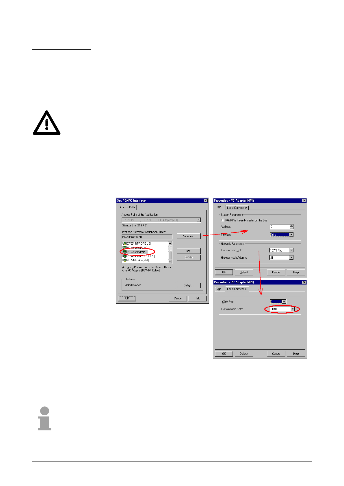
Chapter 3 Deployment CPU 21x Manual VIPA CPU 21x
Configure MPI
Approach
Hints for configuring a MPI interface are to find in the documentation of
your programming software. At this place only the usage of the "Green
Cable" from VIPA shall be shown, toget her with the program ming tool from
Siemens.
The "Green Cable" establishes a connection between the COM interface of
the PC and the MP
2
I interface of the CPU.
Attention!
Please regard, that you may use the "Green Cable" exclusively at VIPA
CPUs with MP
Please regard the hints f or deploying the G reen Cable and the MP
2
I-interface!
2
I jack in
chapter Principles.
• Start the SIMATIC Manager fr om Siemens.
• Choose Options > Configure PU/PC inter f ace.
→ The following dialog window appears, where you may configure the
used MPI interface:
• Choose " PC Adapter (MPI) ", possibly you have to add this first.
• Click on [Properties].
→ In the following two dialog windows you may configure your PC
adapter like shown in the picture.
Note!
Please make sure to adj ust the transf er rate to 38400Baud when using the
"Green Cable" from VIPA.
3-12 HB103E - Rev. 05/45
Page 71

Manual VIPA CPU 21x Chapt e r 3 Depl oyment CPU 21x
Usage of the
MMC
Needed files
Transfer
CPU →→→→ MMC
As external storage medium the Multi Media Card (MMC) is used (OrderNo.: VIPA 953-0KX00).
The reading of the MMC takes always place after an O VERALL RESET.
You may write on the MMC via a write command from the hardware
configurator from Siemens or with a MMC reading device from VIPA
(OrderNo.: VIPA 950-0AD00). Thus it is possible to create your
applications at the PC, copy them on MMC and transfer them into the CPU
by plugging-in the MMC.
The MMC modules are delivered preformatted with the file system FAT 16.
There may exist several proj ects and subf olders on one MMC module. You
just have to tak e care, that t he recent project is stor ed in the root directory
and has the name: S7PROG.WLD.
When the MMC has been installed, the write command stores the
application program of t he bat tery buffered RAM at the MMC.
The write command is controlled by means of the Siemens hardware
configurator via PLC > Copy RAM to ROM.
During the write operation the yellow "MC"-LED of the CPU is blinking.
Transfer
MMC →→→→ CPU
The transfer of the user application f r om the MMC to the CPU always takes
place after an OVERALL_RESET. The blinking of the yellow "MC"-LED
indicates the active transfer process.
If there is no valid user applicat ion on the MMC or if the transf er fails, an
OVERALL_RESET of the CPU takes place and the "STOP"-LED blinks
three times.
Note!
If the user application exceeds the user memor y of the CPU, the content of
the MMC is not transferred into the CPU.
If you initiate a write command and there is no MMC plugged in, an error
message about insufficient memory occurs.
It is advisable to compress the application program before transferring it
into the CPU, because this is not initialized automatically.
HB103E - Rev. 05/45 3-13
Page 72

Chapter 3 Deployment CPU 21x Manual VIPA CPU 21x
Operating modes
Outline
Operating mode
STOP
The CPU can be in one of 3 operating modes:
• STOP
• START-UP
• RUN
Certain conditions in the operating modes START-UP and RUN require a
specific reaction from the system program. In this case the application
interface is often provided by a call to an organization block that was
included specifically for this event.
• Processing of the application prog ram has stopped.
• If the program was being processed, the values of counters, timers,
flags and the contents of the process image are retained during the
transition to the STOP mode.
• Outputs are inhibited, i.e. all digital outputs are disabled.
• RUN-LED off
• STOP-LED on
Operating mode
START-UP
Operating mode
RUN
• During the transit ion from STOP to RUN a call is issued to t he start-up
organization block OB 100. The length of this OB is not limited. The
processing time f or this OB is not monitor ed. T he star t- up OB may issue
calls to other blocks.
• All digital outputs are disabled during the start-up, i.e. outputs are
inhibited.
• RUN-LED blinks
• STOP-LED off
When t he CPU has completed the start-up OB, it assumes the operating
mode RUN.
• The application program in OB 1 is processed in a cycle. Under the
control of alarms other pr ogram sections can be included in the cycle.
• All timer and counter s being started by the program are active and the
process image is updated with every cycle.
• The BASP-signal (outputs inhibited) is deactivated, i.e. all digital outputs
are enabled.
• RUN-LED on
• STOP-LED off
3-14 HB103E - Rev. 05/45
Page 73
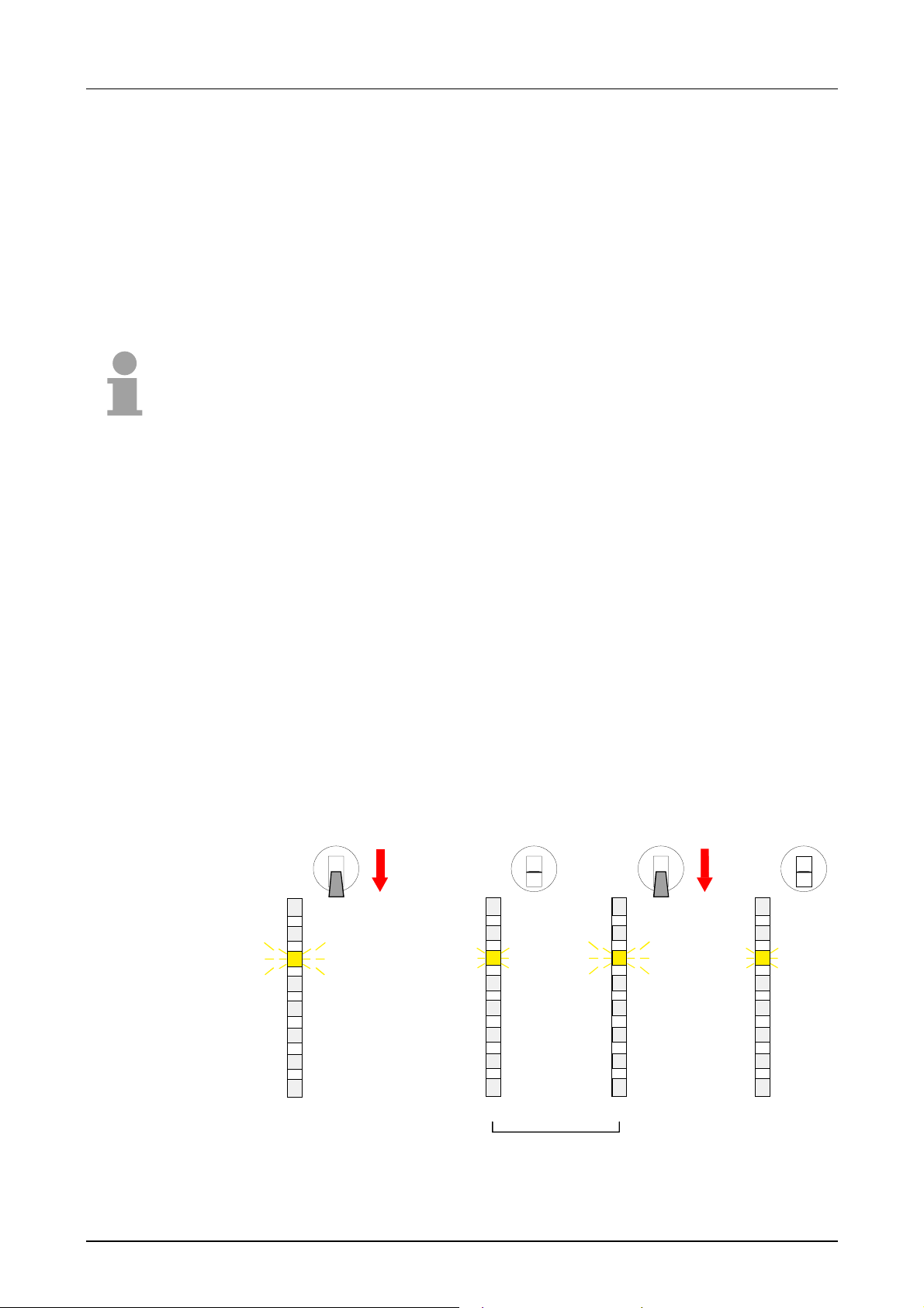
Manual VIPA CPU 21x Chapt e r 3 Depl oyment CPU 21x
Overall Reset
Outline
Overall reset by
means of the
function selector
During the OVERALL_RESET the entire user memory (RAM) is erased.
Data located in the memory card is not affected.
You have 2 options to initiate an OVERALL RESET:
• initiate the overall reset by means of the function selector switch
• initiate the overall reset by means of the Siem ens SIMATIC Manager
Note!
You should always issue an overall reset to your CPU before loading an
application program into your CPU to ensure that all blocks have been
cleared from the CPU.
Condition
The operating mode of the CPU is STOP. Place the function selector on
the CPU in position "ST" → the S-LED is on.
Overall reset
• Place the function selector in the position MR and hold it in this position
for app. 3 seconds. → The S- LED chang es f rom blinking to permanent ly
on.
• Place the function selector in the position ST and switch it to MR and
quickly back to ST within a period of less t han 3 seconds.
→ The S-LED blinks (overall reset procedure).
• The overall reset has been completed when the S-LED is on
permanently. → The S-LED is on.
The following figure illust r ates the above procedure:
RN
ST
MR
3Sec.
RN
ST
MR
RN
ST
MR
RN
ST
MR
R
S
PW
SF
FC
MC
R
S
PW
SF
FC
MC
R
S
PW
SF
FC
MC
R
S
PW
SF
FC
MC
3 Sec.
HB103E - Rev. 05/45 3-15
Page 74

Chapter 3 Deployment CPU 21x Manual VIPA CPU 21x
Automatic reload
Overall reset by
means of the
Siemens SIMATIC
Manager
At this point the CPU attempts t o reload the parameters and the program
from the memory card. → The lower LED (MC) blinks.
When the reload has been completed the LED is extinguished. The
operating mode of the CPU will be STOP or RUN, depending on the
position of the function selector .
Condition
The operating mode of the CPU must be STOP.
You may place the CPU in STOP mode by the menu command
PLC > Operating mode.
Overall reset
You may request the OVERALL_RESET by means of the menu command
PLC > Clear/Reset.
In the dialog window you may place your CPU in STOP mode if this has not
been done as yet and start the overall reset.
The S-LED blinks during the overall r eset procedure.
When t he S-LED is on permanently the overall reset procedure has been
completed.
Automatic reload
Set back to factory
setting
At this point the CPU attempts t o reload the parameters and the program
from the memory card. → The lower LED (without label) blinks.
When the reload has been completed, the LED is extinguished. The
operating mode of the CPU will be STOP or RUN, depending on the
position of the function selector .
The following approach deletes the internal RAM of the CPU completely
and sets it back to the delivery state.
Please regard that the MPI address is also set back t o default 2!
• Push down the reset lever for app. 30 seconds. The ST- LED blinks.
After a few seconds the LED turns t o static light. Count the number
of static light phases because now the LED switches between static
light and blinking.
th
• After the 6
static light you release the reset lever and push it down
again shortly. Now the gr een RUN-LED is on once. This m eans that
the RAM is totally deleted.
• Turn the power supply off and on again.
3-16 HB103E - Rev. 05/45
Page 75

Manual VIPA CPU 21x Chapt e r 3 Depl oyment CPU 21x
Firmware update
Outline
Find out CPU
firmware version
At CPU, DP-Master and CP you may execute a firmware update via MMC
starting with firmware version 3.3.3.
The latest 2 firmware versions can be found in the service area at
www.vipa.de and at the ftp server at ftp.vipa.de.
Attention!
When installing a new firmware you have to be extremely caref ul. Under
certain circumstances you m ay destroy the CPU, f or example if the voltage
supply is interrupted during transfer or if the firmware file is defective.
In this case, please call the VIPA-Hotline!
Please regard that the version of the update firmware has to be different
from the existing fir m ware other wise no update is executed.
A label on the rear of the module indicates t he firmware version.
You may display the current firmware version of your CPU via the SIMATIC
Manager from Siemens. To display the firmware version, you g o online with
the CPU via your PG or PC and start the SIMATIC Manager f rom Siemens.
Via PLC > Module status, register "Gener al", the current firmware version
is evaluated and displayed.
Preconditions for
ftp access
Note!
The server stores always the latest two firmware versions.
For the display of ft p sites in your web browser you may have to execute
the following adjustments:
Internet Explorer
ftp access only with version 5.5 or higher
Options > Internet options, Regist er " Advanced" in the ar ea " Br owsing":
- activate: "Enable folder view for ft p sit es"
- activate: "Use passive ftp ..."
Netscape
ftp- access only with version 6.0 or higher
No further adjustment s are required
If you still have problems with the ftp access, please ask your system
operator.
HB103E - Rev. 05/45 3-17
Page 76

Chapter 3 Deployment CPU 21x Manual VIPA CPU 21x
MMC update using
reserved file names
By means of reserved file names in the CPU 21x you may transfer the
firmware updates per MMC for the following components:
Component Possible with
CPU version
CPU V. 3.3.3
Profibus master V. 3.0.5 Bb000089.version dpm00.bin
CANopen master V. 3.4.8 and
File name at ftp server New file name
at MMC
order no._release.version
VIPA_order no._version.bin
firmware.bin
*)
can00.bin
CAN master V. 1.0.7
CP (21x-2BT10) V. 3. 6.7
*)
When deploying the CPU firmware version V 3.3.3, the file name of the firmware update has to be dpm. bi n!
px000018_version.zip
px000018.pkg
Load firmware and
transfer it to MMC
with reserved file
name
• Go to ftp.vipa.de/support/firmware
• Navigate to System 200V. Here the components corresponding
firmware can be found.
• Download the corresponding file. The table above can be used for a
check of the file name structure.
• Copy the file to your MMC. Rename the file to the corresponding
reserved file name of the table.
Transfer firmware
from MMC into
CPU
• Get the RUN-STOP lever of your CPU in position STOP.
• Turn off the power supply.
• Plug the MMC with the fir mware into the CPU. Please take care of the
correct plug-in direction of t he MMC.
• Turn on the power supply.
• After a short boot- up time, the alt ernate blink ing of the LEDs SF and FC
shows that the firmware file has been found on the MMC.
• You start the t ransf er of t he firm ware as soon as you tip the RUN/STOP
lever downwards to MRES within 10s. The CPU shows the transfer via a
LED blink line.
• During the update process, the LEDs SF, FC and MC are alternately
blinking. This may last several minutes.
• The update is successful finished when all CPU-LEDs are on. I f they are
blinking fast, an err or occur red.
Note!
Starting with the W inNCS version 3.1.1 you may update the f irm ware of the
CP online via the parameterization window. The CP portion supports this
function from CP firmware version 2.1.2 on.
3-18 HB103E - Rev. 05/45
Page 77
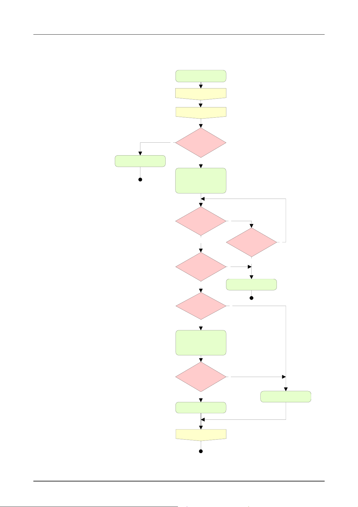
Manual VIPA CPU 21x Chapt e r 3 Depl oyment CPU 21x
Flowchart for
firmware update
The following flowchart illustrates the CPU behavior at firmware update:
Power Off
Plug-in MMC
Power On
Switch=Stop?
n
CPU goes in RUN
SF and FRCE are
blinking alternately
y
LED
Switch=MR?
n
y
Update/Config
file(s) on
MMC?
y
File(s) OK?
Product name..
y
FW Update/Config.
SF, FRCE, MMC are
blinki ng alternately
(ready) with
error?
n
All LEDs ar e on
10 seconds
passed?
y
n
CPU goes in STOP
n
y
All LEDs are blinking
n
Power Off
HB103E - Rev. 05/45 3-19
Page 78

Chapter 3 Deployment CPU 21x Manual VIPA CPU 21x
Using test functions for the control and monitoring of variables
Outline
Test > Status
For troubleshooting purposes and to display the status of certain variables
you may access certain test functions via the menu item Test of the
Siemens SIMATIC Manager.
The status of the operands and the VKE are displayed by means of the test
function Test > Status.
You are able to modify and/or display the status of variables by means of
the test function PLC > Monitor/contr ol variables.
This test function displays the current signal state and the VKE of the
different operands while the prog ram is being executed.
It is also possible to enter corrections to t he pr ogram.
Note!
When using t he test function Monitoring the PLC has to be in RUN mode!
The processing of states m ay be interrupted by means of jump commands
or by timer and process-related alarms. At the breakpoint the CPU stops
collecting data f or the stat us display and instead of t he req uired dat a it only
provides the PG with data containing the value 0.
For this reason jumps or time and process alarm s may result in the value
displayed during program execution remaining at 0 for the items below:
• the result of the logical oper ation VKE
• Status / AKKU 1
• AKKU 2
• Condition byte
• absolute memory address SAZ. In this case SAZ is f ollowed by a "?".
The interruption of the processing of statuses does not change the
execution of the program but it only shows that the data displayed is no
longer valid after fr om the point where the interrupt occurred.
3-20 HB103E - Rev. 05/45
Page 79

Manual VIPA CPU 21x Chapt e r 3 Depl oyment CPU 21x
PLC >
Monitor/control
variables
This test function returns the condition of a selected operand (inputs,
outputs, flags, data word, counters or timer) at the end of program
execution.
This information is obtained from the process image of the selected
operands. During the "processing check " or in operating mode STOP the
periphery is read directly from the inputs. Otherwise only the process
image of the selected operands is displayed.
Control of outputs
It is possible to check the wiring and proper operat ion of output modules.
You may set outputs to any desired status with or without a control
program. The process image is not modified but outputs are no longer
inhibited.
Control of variables
The following variables may be modified:
E, A, M, T, Z, and D.
The process image of binary and digital operands is modified independen-
tly of the operating mode of the CPU 21x.
When the operating mode is RUN the program is executed with the
modified process variable. When the program continues they may,
however, be modified again without notification.
Process variables are controlled asynchronously with respect to the execution sequence of the program .
HB103E - Rev. 05/45 3-21
Page 80

Chapter 3 Deployment CPU 21x Manual VIPA CPU 21x
3-22 HB103E - Rev. 05/45
Page 81

Manual VIPA CPU 21x Chapter 4 Deployment of the CPU 21x-2BT10 with TCP/IP
Chapter 4 Deployment of the CPU 21x-2BT10 with TCP/IP
Outline
Contents
The following chapter describes applications of the CPU 21x-2BT10 and
the communication using TCP/IP. Please regard the chapter „Fast
introduction“ where you find all information compressed required for the
project engineering of the CPU 21x-2BT10. After the fast introduction, the
mentioned steps are described in detail.
The following text describes:
• Basics about a Twisted-Pair network
• Project engineering of a CP communication
• ORG format f or t he communication with a foreign system
• Example
Topic Page
Chapter 4
Industrial Ethernet in automation..........................................................4-2
ISO/OSI reference model.....................................................................4-3
Principles..............................................................................................4-6
Protocols..............................................................................................4-7
IP address and subnet .......................................................................4-10
Network planning ...............................................................................4-12
Communication possibilities of the CP ...............................................4-15
Function overview.............................................................................. 4-18
Fast introduction.................................................................................4-19
Hardware configuration......................................................................4-23
Configure connections........................................................................4-26
SEND/RECEIVE with PLC program...................................................4-32
Project transfer...................................................................................4-37
NCM diagnostic – Help for error diagnostic........................................4-39
Coupling to other systems.................................................................. 4-42
Example communication CPU21x-2BT10...........................................4-45
Deployment of the CPU 21x-2BT10 with TCP/IP...........4-1
HB103E - Rev. 05/45 4-1
Page 82
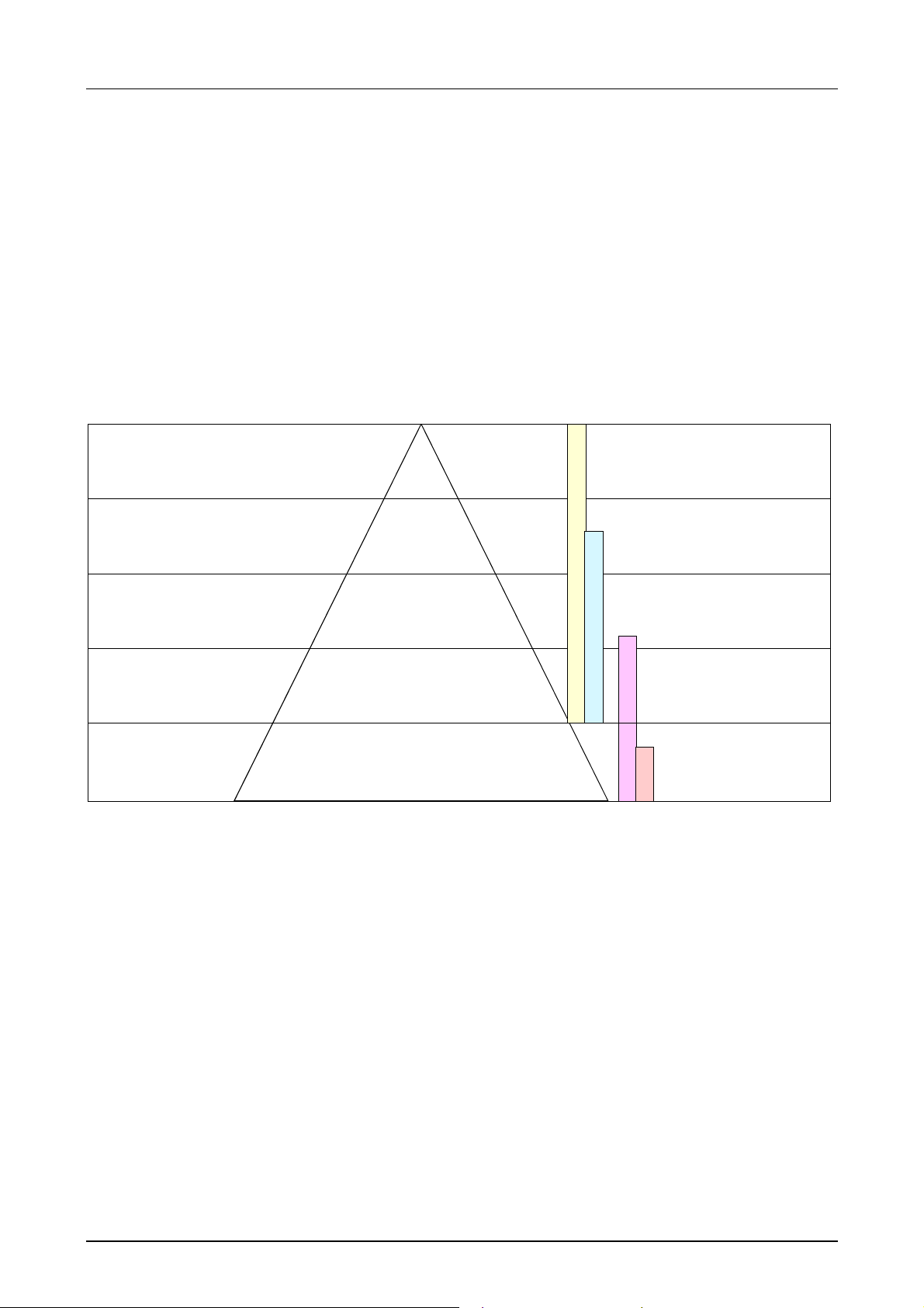
Chapter 4 Deployment of the CPU 21x-2BT10 with TCP/IP Manual VIPA CPU 21x
Industrial Ethernet in automation
Overview
Operational layer
Management layer
System layer
The flow of information in a company presents a vast spectrum of
requirements that must be met by the communication systems. Depending
on the area of business the bus system or LAN must support a different
number of users, different volumes of data must be transferred and the
intervals between transfers may vary, etc.
It is for this reason t hat different bus systems are em ployed depending on
the respective task. These may be subdivided into different classes. The
following model depicts t he relationship between the different bus system s
and the hierarchical structures of a com pany:
Industrial
Plant
computer
PPS CAD
Plant-oriented
control computer
manufacturing, stock,
production data
PPS CAD
Machine and control
computer
Ethernet
H1
Prozess layer
Sensor / actuator
layer
Industrial Ethernet
Peripheral systems. machines, CNC, NC,
controllers (PLC), measuring systems
sensor, actuator, regulator, multiplexer, operating consoles
Peripheral components
Field bus
Sensor / actuator
Bus
Industrial Ethernet is an electrical net based on shielded twisted pair
cabeling or optical net based on optical fibre.
Industrial Ethernet is defined by the int ernational standar d IEEE 802.3. The
net access of Industrial Ethernet corresponds to IEEE 802.3 - CSMA/CD
(Carrier Sense Multiple Access/Collision Detection) scheme: every station
“listens” on the bus cable and r eceives communication messages that are
addressed to it.
Stations will only initiate a transmission when the line is unoccupied. In the
event that two participants should start transmitting simultaneously, they
will detect this and stop transmitting to restart after a random delay time
has expired.
Using switches there is the possibility for communication without collisions.
4-2 HB103E - Rev. 05/45
Page 83

Manual VIPA CPU 21x Chapter 4 Deployment of the CPU 21x-2BT10 with TCP/IP
ISO/OSI reference model
Overview
The ISO/OSI reference model is based on a proposal that was developed
by the International Standards Org anization (ISO). This represent s the first
step towards an international standard for the different protocols. It is
referred to as the ISO-OSI layer model. OSI is the abbreviation for Open
System Interconnection, the communication between open systems. The
ISO/OSI reference model does not represent a network architecture as it
does not define t he services and protocols used by the different layers. The
model simply specifies the tasks that t he different layers must perform.
All current communication systems are based on the ISO/OSI reference
model which is defined by the ISO 7498 standard. The reference model
structures communication systems into 7 layers that cover different
communication tasks. In this manner the complexity of the communication
between different systems is divided amongst different layers to simplify
the task.
The following layers have been defined:
Layer Function
Layer 7 Application Layer
Layer 6 Presentation Layer
Layer 5 Session Layer
Layer 4 Transport Layer
Layer 3 Network Layer
Layer 2 Data Link Layer
Layer 1 Physical Layer
Depending on the complexity and the requirements of the communication
mechanisms a communication system may use a subset of these layers.
HB103E - Rev. 05/45 4-3
Page 84

Chapter 4 Deployment of the CPU 21x-2BT10 with TCP/IP Manual VIPA CPU 21x
Layers
Layer 1 Bit communication layer (physical layer)
The bit communication layer (physical layer) is concerned with the transf er
of data bits via the communication channel. This layer is therefore
responsible for the m echanical, elect rical and the pr ocedural int erf aces and
the physical communication medium locat ed below the bit communication
layer:
• Which voltage r epr esents a logical 0 or a 1?
• The minimum time that the voltage be present to be recognized as a bit.
• The pin assignment of the r espective interface.
Layer 2 Security layer (data link layer)
This layer performs error-checking functions for bit strings transferred
between two communicating partners. This includes the recognition and
correction or flagging of communication errors and flow control functions.
The security layer (data link layer) converts ra w communication data into a
sequence of frames. This is where frame limits are inserted on the
transmitting side and where the receiving side detects them. These limits
consist of special bit patterns that are inserted at the beginning and at t he
end of every frame. The securit y layer often also incorporates flow control
and error detection functions.
The data security layer is devided into two sub-levels, the LLC and the
MAC level.
The MAC (Media Access Control) is the lower level and controls how
senders are sharing a single transmit channel.
The LLC (Logical Link Control) is the upper level that establishes the
connection for transfer r ing the data frames f r om one device into t he ot her.
Layer 3 Network layer
The network layer is an agency layer.
Business of this layer is to control the exchange of binary data between
stations that are not directly connected. It is responsible for the logical
connections of layer 2 communication. Layer 3 supports the ident ification of
the single network addresses and the establishing and disconnecting of
logical communication channels.
Additionally, layer 3 manages the prior transfer of data and the error
processing of data packets. IP (Internet Protocol) is based on Layer 3.
Layer 4 Transport layer
Layer 4 connects the network structures with the structures of the hig her
levels by dividing the messages of higher layers into segments and pass
them on to the network layer. Hereby, the transport layer converts the
transport addresses into network addresses.
Common transport protocols are: TCP, SPX, NWLink and NetBEUI.
4-4 HB103E - Rev. 05/45
Page 85

Manual VIPA CPU 21x Chapter 4 Deployment of the CPU 21x-2BT10 with TCP/IP
Layers
continued...
Layer 5 Session layer
The session layer is also called the communication control layer. It relieves
the communication between service deliverer and the requestor by
establishing and holding the connection if the transport system has a short
time fail out.
At this layer, logical users may communicate via several connections at the
same time. If the tr ansport system fails, a new connection is established if
needed.
Additionally this layer provides methods for control and synchronization
tasks.
Layer 6 Presentation layer
This layer manages the presentation of the messages, when different
network systems are using diff er ent representations of data.
Layer 6 converts the data into a format that is acceptable for both
communication partners.
Here compression/decompression and encrypting/decrypting tasks are
processed.
This layer is also called interpreter. A t ypical use of this layer is the terminal
emulation.
Layer 7 Application layer
The application layer is the link between the user application and the
network. The tasks of the applicat ion layer include the network services like
file, print, message, data base and application services as well as the
according rules.
This layer is composed from a series of protocols that are permanently
expanded following the increasing needs of the user.
HB103E - Rev. 05/45 4-5
Page 86

Chapter 4 Deployment of the CPU 21x-2BT10 with TCP/IP Manual VIPA CPU 21x
Principles
Network (LAN)
Twisted Pair
A network res. LAN (local area network) provides a link bet ween different
stations that enables them to communicat e with each other.
Network stations consist of PCs, I PCs, TCP/IP adapters, etc.
Network stations are separated by a minimum distance and connected by
means of a network cable. The combination of network stations and the
network cable represent a complete segment .
All the segments of a network form the Ethernet (physics of a net work ) .
In the early days of net working the Triaxial- (yellow cable) or thin Ethernet
cable (Cheapernet) was used as communication medium. This has been
superseded by the twisted-pair network cable due to its immunity to
interference. The CPU 21xNET m odule has a twisted-pair connector.
The twisted-pair cable consists of 8 cores t hat are twisted together in pairs.
Due to these twists this system is provides an increased level of immunity
to electrical interf erence. For linking please use twisted pair cable which at
least corresponds to the category 5.
Where the coaxial Ethernet networks are based on a bus topology the
twisted-pair network is based on a point-to-point schem e.
The network that may be established by means of this cable has a star
topology. Every station is connected to the star coupler (hub/switch) by
means of a separate cable. The hub/switch provides the interface to the
Ethernet.
Hub (repeater)
Switch
The hub is the central element that is r equired to implement a twisted-pair
Ethernet network.
It is the job of the hub to regenerate and to amplify the signals in both
directions. At the same time it must have the facility to detect and process
segment wide collisions and to relay this information. The hub is not
accessible by means of a separate network address since it is not visible to
the stations on the network.
A hub has provisions to interface to Ethernet or to another hub res. switch.
A switch also is a central element for realizing Ethernet on Twisted Pair.
Several stations res. hubs are connected via a switch. Afterwards they are
able to communicate with each other via the switch without interf ering the
network. An intelligent hardware analyzes the incoming teleg rams of every
port of the switch and passes them collision free on to the destination
stations of the switch. A switch optimizes the bandwidth in every connected
segment of a network. Switches enable exclusive connections between the
segments of a network chang ing at request.
4-6 HB103E - Rev. 05/45
Page 87

Manual VIPA CPU 21x Chapter 4 Deployment of the CPU 21x-2BT10 with TCP/IP
Protocols
Overview
TCP/IP
Protocols define a set of instructions or standar ds that enable computer to
establish communication connections and exchange information as error
free as possible.
A commonly established protocol for the standardization of the complete
computer communication is the so called ISO/OSI layer model, a model
based upon seven layers with rules for the usage of hardware and software
(see ISO/OSI reference model above).
The CPU 21xNET from VIPA uses the following protocols
• TCP/IP
• UDP
• RFC1006 (ISO-ON-TCP)
The protocols are described in the following:
TCP/IP protocols are available on all m ajor systems. At the bot tom end t his
applies to simple PCs, through to the typical mini-computer up to
mainframes.
For the wide spread of internet accesses and connections, T CP/IP is often
used to assemble heterogeneous system pools.
TCP/IP, standing f or Transmission Control Protocol and Internet Protocol,
collects a various range of protocols and f unct ions.
TCP and IP are only two of the protocols required for the assembly of a
complete architecture. The application layer provides programs like "FTP"
and "Telnet" for t he PC.
The application layer of the Ethernet part of the CPU 21xNET is defined
with the user application using the standard handling block s .
These user applications use the transport layer with the protocols TCP and
UDP for the data transfer which themselves communicate via the IP
protocol with the internet layer.
HB103E - Rev. 05/45 4-7
Page 88

Chapter 4 Deployment of the CPU 21x-2BT10 with TCP/IP Manual VIPA CPU 21x
IP
The internet protocol covers the network layer (Layer 3) of the ISO/OSI
layer model.
The purpose of IP is to send data pack ages f r om on PC t o another passing
several other PCs. These data packages are referred to as datagrams.
The IP doesn't guarantee the correct sequence of the datagrams nor the
delivery at the receiver.
For the unambiguous identification between sender and receiver 32Bit
addresses (IP addresses) are used that are normally written as four octets
(exactly 8Bit), e.g. 172.16.192. 11.
These internet addresses are defined and assigned worldwide from the
DDN network (Defense Department Network), thus every user may
communicate with all other TCP/IP users.
One part of the address specifies the network, the rest serves the
identification of the participants inside the network. The boarder between
the network and the host part is variable and depends on the size of the
network.
To save IP addresses, so called NAT router are used that have one official
IP address and cover the network. Then the network can use any IP
address.
TCP
Properties
The TCP (Transmission Control Protocol) bases directly on the IP and
thus covers the transport layer (layer 4) of t he OSI layer model. TCP is a
connection orientated end-to-end protocol and serves the logic connection
between two partners.
TCP guarantees the correct sequence and reliability of the data transfer.
Therefore you need a relatively large protocol overhead that slows down
the transfer speed.
Every datagram gets a header of at least 20Byte. This header also
contains a sequence number identifying the series. This has the
consequence that the single datagrams may reach the destination on
different ways through the network.
Using TCP connections, the t eleg ram leng th is not tr ansmitt ed. T his means
that the recipient has to know how many bytes belong to a message. T o
transfer data with variable length you may begin the user data with the
length information and evaluate this at the counter station.
• Besides of the IP address ports are used for the addressing. A port
address should be within the range of 2000...65535. Partner and local
ports may only be identical at one connection.
• Not depending on the used protocol, the PLC needs the VIPA handling
blocks AG_SEND (FC5) and AG_RECV (FC6) for data transfer .
4-8 HB103E - Rev. 05/45
Page 89

Manual VIPA CPU 21x Chapter 4 Deployment of the CPU 21x-2BT10 with TCP/IP
UDP
ISO-on-TCP
RFC1006
The UDP (User Datagram Protocol) is a connection f ree transpor t protocol.
It has been defined in the RFC768 (Request for Comment). Compared to
TCP, it has much fewer characteristics.
The addressing happens via port numbers.
UDP is a fast unsafe protocol for it doesn't care about missing data
packages nor about their sequence.
The TCP transport service works stream orientated. This m eans that data
packages assembled by the user not necessarily have to receive the
partner in the same packaging . Depending on the data amount, packages
may though come in in the correct sequence but differently packed. This
causes that the recipient may not recognize the pack age borders anymore.
For example you may send 2x 10Byte packages but the counter station
receives them as 20Byte package. But for most of the applications the
correct packaging is impor t ant.
Due to this you need another protocol above TCP. This purpose is def ined
in the protocol RFC1006. The prot ocol definition describes the function of
an ISO transport interf ace (ISO 8072) basing upon the transport interface
TCP (RFC793).
The basic protocol of RFC1006 is nearly identical to TP0 (Transport
Protocol, Class 0) in ISO 8073.
For RFC1006 is run as pr otocol for TCP, the decoding takes place in the
data section of the TCP package.
Properties
• In contrast to TCP here the receipt of one telegram is conf ir m ed.
• Instead of ports TSAPs are used f or the addressing besides of the IP
address. The TSAP length may be 1 ... 16Byte. The entry may happen
in ASCII or Hex format. Foreign and local TSAPs may only be identical
at 1 connection.
• Independently of the used protocol the VIPA handling blocks AG_SEND
(FC5) and AG_RECEIVE (FC6) are necessary f or data transfer.
• Contrary to TCP different telegram lengths can be received using
RFC1006.
HB103E - Rev. 05/45 4-9
Page 90

Chapter 4 Deployment of the CPU 21x-2BT10 with TCP/IP Manual VIPA CPU 21x
IP address and subnet
IP address
structure
Net-ID
Host-ID
Subnet mask
Subnet
The IP address is a 32Bit address that m ust be unique within the network.
The IP address consists of 4 numbers t hat are separated by a full stop.
Every IP address is a combination of a Net-ID and a Host-ID and its
structure is as follows:
Range: 000.000.000.000 to 255.255.255. 255
The network administrator also defines IP addresses.
The Network-ID identifies a network res. a network controller that
administrates the network.
The Host-ID mar ks the network connections of a participant (host) to this
network.
The Host-ID can be furt her divided into a Subnet-ID and a new Host-ID by
using an bit for bit AND assig nment with the Subnet mask.
The area of the or ig inal Host-I D that is overwritten by 1 of the Subnet m ask
becomes the Subnet-ID, the rest is the new Host-ID.
Subnet mask binary all "1" binar y all "0"
IPv4 address Net-ID Host-ID
Subnet mask and IPv4 address Net-ID Subnet-ID new Host-ID
A TCP-based communication via point-to-point, hub or switch connection is
only possible between stations with identical Network-ID and Subnet-ID!
Different area must be connected with a router.
The subnet mask allows you to sort the resources following your needs.
This means e.g. that every department g ets an own subnet and thus does
not interfere another depar t m ent.
xxx.xxx.xxx.xxx
Address at first
start-up
4-10 HB103E - Rev. 05/45
At the first start -up the CP does not have
takes place using the following possibilit ies:
• Using Siemens SIMATIC Manager switch PG/PC interface to "TCP/IP...
RFC1006". Via "Assign Ethernet address" sear ch the CP and assign IP
parameters. After that the CP is directly assigned to the new IP
parameters without any restart of t he CPU.
• You may assign an IP address and a subnet mask to your CP with the
help of a "m inimum project" and transfer this via MMC or MPI into the
CPU. After a reboot of the CPU and after switching the PG/PC interface
to "TCP/IP... RFC1006" you may now configure your CPU online via the
CP.
any IP address. The assignment
Page 91

Manual VIPA CPU 21x Chapter 4 Deployment of the CPU 21x-2BT10 with TCP/IP
Address classes
Private IP networks
For IPv4 addresses there are five address format s (class A to class E) that
are all of a length of 4 Byte = 32 Bit .
Class A 0 Network-ID
Host-ID (24 bit)
(1+7 bit)
Class B 10 Network-ID (2+14 bit) Host- I D ( 16 bit)
Class C 110 Network-ID (3+21 bit) Host-ID (8 bit)
Class D 1110 Multicast group
Class E 11110 Reserved
The classes A, B and C are used for individual addresses, class D for
multicast addresses and class E is reserved for special purposes.
The address for m at s of the 3 classes A, B, C are only differing in the length
of Network-ID and Host-I D.
To build up private IP-Networks within the internet, RFC1597/1918
reserves the following address areas:
Network
Start IP End IP Standard subnet mask
class
A 10.0.0.0 10.255.255.255 255.0.0.0
B 172.16.0.0 172.31.255.255 255.255.0.0
C 192.168.0.0 192.168.255.255 255.255.255.0
(The Host-ID is underlined.)
Reserved
Host-Ids
These addresses can be used as net-ID by several organizations without
causing conflicts, for these IP addresses are neither assigned in the
internet nor are routed in the internet.
Some Host-IDs are reserved for special pur poses.
Host-ID = 0 Identifier of this network, reserved!
Host-ID = maximum (binary complete 1) Broadcast address of this network
Note!
Never choose an IP address with Host-ID=0 or Host-ID=maximum!
(e.g. for class B with subnet mask = 255.255.0.0, the "172.16.0.0" is
reserved and the "172.16.255.255" is occupied as local broadcast address
for this network.)
HB103E - Rev. 05/45 4-11
Page 92

Chapter 4 Deployment of the CPU 21x-2BT10 with TCP/IP Manual VIPA CPU 21x
Network planning
Standards and
guidelines
ANSI American National Standards Institute
CCITT Comm ittee Consultative Internationale de Telephone et Telegraph.
ECMA European Computer Manuf act urers Association.
EIA Electrical Industries Association (USA)
The applicable rules and regulations have to be satisfied in order to
establish reliable communications between the diff er ent stations.
These agreements define the f orm of t he data protocol, the method of bus
access and other principles that are important for reliable communications.
The VIPA CPU 21xNET was developed in accordance with the standards
defined by ISO.
International and national committees have def ined the following standards
and guidelines for networking t echnologies:
The ANSI X3T9.5 standard cur rently defines the provisions for high-s peed
LANs (100 MB/s) based on fiber optic technology.
(FDDI) Fiber Distributed Data Interface.
Amongst others, this advisory committee has pr oduced t he pr ovisions for
the connection of industrial networks (MAP) to office networks (TOP) on
Wide Area Networks (WAN) .
Has produced various MAP and TOP standards.
This committee has issued standard def initions like RS-232 (V.24) and
RS-511.
IEC International Electrotechnical Com mission.
Defines certain special standards, e.g . for the Field Bus.
ISO International Organization for Standardization.
This association of national standards organizations developed the OSImodel (ISO/TC97/SC16). It provides the framework f or the standardization
of data communications. ISO standards are included in different nat ional
standards like for example UL and DIN.
IEEE Instit ut e of Electrical and Electronic Engineers (USA) .
The project-group 802 deter mines LAN-standards for transf er rates of 1 to
1000MB/s. IEEE standards often for m the basis for ISO-standards, e. g.
IEEE 802.3 = ISO 8802.3.
4-12 HB103E - Rev. 05/45
Page 93
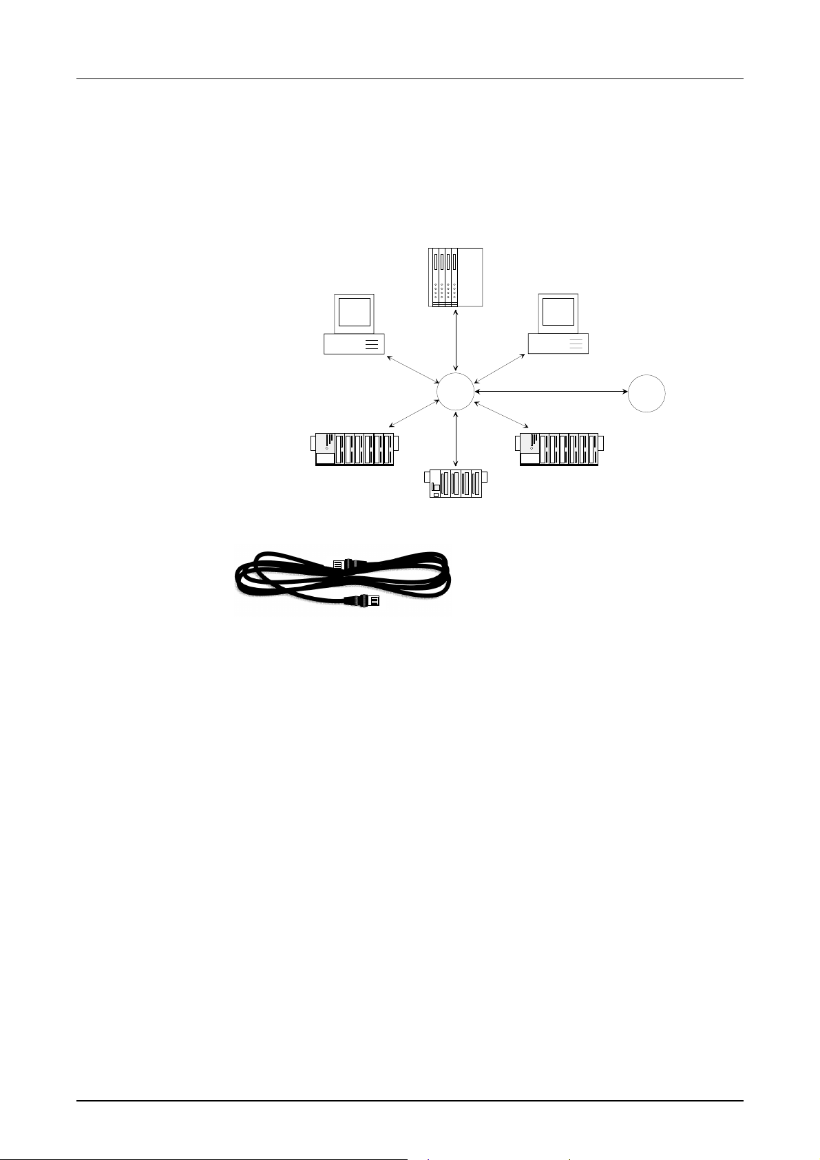
Manual VIPA CPU 21x Chapter 4 Deployment of the CPU 21x-2BT10 with TCP/IP
Overview of
components
Analyzing the
requirements
The CP is exclusively used for employment in a Twisted-Pair network.
Within a Twisted-Pair network all participating stations are connected in
star topology via a T wisted-Pair cable to a hub/switch which is also able to
communicate with another hub/switch. Two connected stations are building
a segment where the length of t he Twisted-Pair cable between two stations
must be max. 100m.
Hub/
Switch
Hub/
Switch
Twisted Pair cable
At twisted pair cable has 8 conductors
twisted together in pairs. The different
conductors have a diameter of 0.4 to
0.6mm.
For linking please use twisted pair cable
which at least corresponds to the
category 5.
• What is the size of the area that must be served by the network?
• How many network segments provide the best solution for t he physical
(space, interference relat ed) condit ions encount er ed on site?
• How many network stations (SPS, IPC, PC, transceiver, bridges if
required) must be connected to the cable?
• What is the distance between the different stations on the network?
• What is the expected “growth rate” and the expected number of
connections that must be catered for by the system?
• What data amount has to be handled (band width, accesses/sec.)?
Drawing a
network diagram
Draw a diagram of the network. Identify every hardware item (i.e. station
cable, hub, switch). Observe the applicable rules and restrictions.
Measure the distance between all components to ensure that the maximum
length is not exceeded.
HB103E - Rev. 05/45 4-13
Page 94

Chapter 4 Deployment of the CPU 21x-2BT10 with TCP/IP Manual VIPA CPU 21x
Linking with
NetPro
Net-Project
variants
1 subnet 1 project
2 or more subnets 1 project
1 or more subnets –
several part
projects
Subnet exceeding
connections
Please regard that the following software packages must be installed for
the project engineering:
• Siemens SIMATIC Manager V. 5.1 and vipa_21x.gsd (is included).
• Siemens SIMATIC NET
To enable the stations to communicate with each other you have to
configure the required (sub)nets in the Siemens SIMATIC Manager res.
NetPro following this approach:
• Create one or more subnets of the wanted type in your proj ect .
• Adjust the properties of the subnet s.
• Connect your participants logically to the subnet.
• Establish communication connections between the single stations.
You may administrate several subnets in one project. Every station has to
be created once. A station may be assigned to several subnets by
assigning the CPs accordingly.
In the following typical project variants f or networks are listed:
The simplest case is a plant with stations that have to be connected via
one subnet of the type Industrial Ether net .
For this you create an object "Ethernet". Stations that are created in the
same project refer to this object when they are configured as net knots.
They may then be selected directly. Foreign devices are listed in this
subnet as "Other station" during project engineering.
Due to diff er ent tasks of t he stations or due to the expansion of your plant it
may be necessary to create several nets. Here you may create several
subnets in one project and configur e t he stations easily for communication.
At complex linked plants it is sensible t o administrate plant part s in several
part projects. Here it may be necessary to create project exceeding
connections. For this the Siemens SIMATIC Manager starting with V5.2
provides the multi project funct ion. This funct ion allows you to split projects
and join them again. A more detailed description is to be found in the
manual of the Siemens SIMATIC Manager.
These are connections that long into another subnet due to the complexity
of the plant. The subnets are connected via a router. By setting a router
address during the hardware configurat ion of your CP you may instruct the
CP to include the according subnet via this router for communication.
4-14 HB103E - Rev. 05/45
Page 95
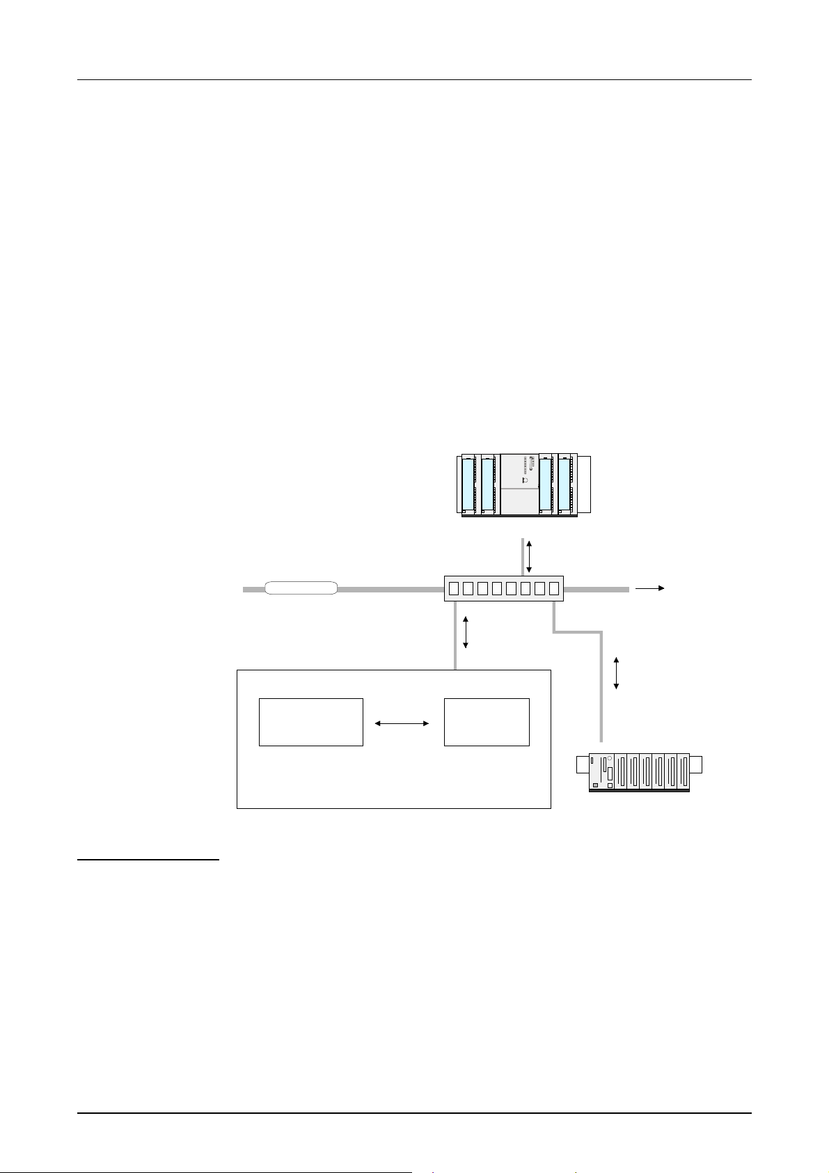
Manual VIPA CPU 21x Chapter 4 Deployment of the CPU 21x-2BT10 with TCP/IP
A
Communication possibilities of the CP
Communication
between CP 243
and CPU
The internal CP of the CPU 21x-2BT10 is directly connected to the CPU via
a Dual-Port-RAM. The CPU manages the data exchange with the VIPA
handling blocks AG_SEND (FC5) and AG _RECV ( FC6).
The communication via the according protocols are controlled by
connections that are paramet erized in the Siemens pr oject engineer ing t ool
NetPro and that m ay be transf erred into the CPU via MMC, MPI or directly
via Ethernet.
For the transfer via Ethernet, your CP must be connected to Ethernet with
valid IP parameters. The assignment takes place either using the
corresponding menu item of the Siemens SIMATIC Manager or via a
minimum project where the IP parameter s are defined. This proj ect can be
transferred to the CPU via MMC or MPI.
System 300S
CPU 31xSN/NET
Frames
dditional interfaces
Ethernet
Ethernet
Switch
Communication
types
PG/OP
communication
Frames
CPU 21xNET
Application
program
(SEND, RECEIVE)
Daten
HTBs
CPCPU
Connections
configured
with NetPro
System 200V
Frames
CPU 21xNET
The CP supports the following communicat ion t ypes:
• PG/OP communication
• Configurable connections
The PG/OP communication serves the loading of programs and
configuration data, f or test and diag nostic f unct ions as well as for oper ating
and monitoring a plant. Here you may access the CPU online via the CP
(Ethernet).
With CP f irmware version 1.7.4 and up a simultaneous access of up to 32
participants is possible. Please note for each PG and O P communication 1
connection is reserved.
HB103E - Rev. 05/45 4-15
Page 96

Chapter 4 Deployment of the CPU 21x-2BT10 with TCP/IP Manual VIPA CPU 21x
Configurable
connections
Configurable connections are connections f or the communication between
PLC stations. The connections may be config ur ed with the Siemens proj ect
engineering tool NetPro.
The following table shows the combination option with the different
operating modes:
Combination
options
Connection partner Connection type Conn. Establ. Connection Operating mode
(in recent project)
Unspecified in NetPro
(in recent project)
Unspecified in NetPro
(in "unknown project") active
All Broadcast stations UDP All Multicast stations UDP -
TCP / ISO-on-TCP active/passive Specified in NetPro
UDP -
TCP / ISO-on-TCP
UDP - specified SEND/RECEIVE
TCP / ISO-on-TCP
UDP -
specified SEND/RECEIVE
active specified SEND/RECEIVE
passive
passive
part specified
(Port)
unspecified
unspecified
(connection
name)
unspecified
(connection
name)
unspecified
(connection
name)
specified (Port,
Broadcast addr)
specified (Port,
Multicast group)
SEND/RECEIVE
FETCH PASSIV
WRITE PASSIV
SEND/RECEIVE
SEND/RECEIVE
FETCH PASSIV
WRITE PASSIV
SEND/RECEIVE
SEND
SEND/RECEIVE
Connection partner
Connection partner are stations at the counter side.
Specified connection partner
Every station configured in the Siemens SIMATIC Manager is entered in
the list of connection partners. By sett ing an IP addr ess and a subnet mask
these stations are uniquely specified.
Unspecified connection partner
You may also set an unspecified connection partner. Here the connect ion
partner may be within the recent project or within an unknown project.
Connection commands to an unknown project must be defined via an
unique connection name that has to be used in the projects of both
stations. Due to the assignment via a connection name, the connection
itself remains unspecified.
All broadcast participants
Only with UDP connections you may here send messages to all available
broadcast participants. The reception is not possible. The broadcast
participants are specified via one
port and one broadcast address at
sender and receiver.
All multicast participants
This setting allows you to send and receive multicast telegrams between
the multicast participants. By setting of one
port and one multicast group
for sender and receiver the multicast participants are specified.
4-16 HB103E - Rev. 05/45
Page 97

Manual VIPA CPU 21x Chapter 4 Deployment of the CPU 21x-2BT10 with TCP/IP
Connection types
Connection
establishment
Connection
Operating modes
For the communication the following connection types are available:
• TCP res. ISO-on-TCP for the secured data transfer of related data
blocks between two Ethernet participants.
• UDP for the unsecured data transf er of related data blocks between two
Ethernet.
Using configurable connections there is always one station that actively
establishes a connection. The counter station waits passively for the active
connection. Only then productive data can be transferr ed.
By setting IP address and port/TSAP of the counter station, a connection is
specified. Active connections must always be set specified. An unspecified
connection which is only possible for passive connection establishment, I P
address and port/TSAP of t he counter station are not requir ed for telegram
evaluation.
There is also an option for part specified connections. The part
specifications happens via the setting of the port. An IP address is not
required.
Depending on the connection, the following operat ing modes are available:
SEND/RECEIVE
The SEND/RECEIVE interface allows the program controlled communication to any partner station via a configured connection. Here the
data transfer happens by call f rom your user application. The FC5 and FC6
that are part of the VI PA block library are serving as interface.
This enables your control to send messages depending on process events.
FETCH/WRITE PASSIVE
With the help of FETCH/WRITE services partner systems have the direct
access to memory areas. This are "passive" communication connections
that have to be configured. The connections are "actively" established by
the connection partner (e.g. Siem ens- S5) .
FETCH PASSIVE (request data)
FETCH allows a partner system to request dat a.
WRITE PASSIVE (write dat a)
This allows a partner system to write data in the data area of the CPU.
HB103E - Rev. 05/45 4-17
Page 98

Chapter 4 Deployment of the CPU 21x-2BT10 with TCP/IP Manual VIPA CPU 21x
Function overview
Outline
Configurable
connections
In the following t he funct ions are listed t hat are supported by the CP of the
CPU 21x-2BT10 starting with CP firmware version 1. 7. 4:
Function Property
Maximum number of
productive connections
TCP connections SEND, RECEIVE, FETCH PASSIVE, WRITE
ISO-on-TCP
connections
(RFC1006)
UDP connections SEND and RECEIVE
UDP Broadcast
connection
UDP Multicast
connection
Data block length max. 64kByte (max. 2KByte at UDP)
VIPA handling blocks For connection commands at the PLC:
16
PASSIVE
Connection establishment active and passive,
supports unspecified connection partner
SEND, RECEIVE, FETCH PASSIVE, WRIT E
PASSIVE
Connection establishment active and passive,
supports unspecified connection partner
The transfer of t he telegrams is not
acknowledged, i.e. the loss of messages is not
recognized by the send block.
SEND
SEND and RECEIVE
AG_SEND (FC5) / AG_RECEIVE (F C6)
Any call without lock in all OBs
PG connections
and diagnostic
Function Property
Maximum number of
PG/OP connections
Diagnostic Supports NCM diagnostic via Ethernet
Search within network Supports Siemens SIMATIC Manager search
10/100MBit Switch happens automatically
32 (each 1 connection is reserved for PG and OP)
4-18 HB103E - Rev. 05/45
Page 99

Manual VIPA CPU 21x Chapter 4 Deployment of the CPU 21x-2BT10 with TCP/IP
Fast introduction
Overview
At the firs t start-up of a CPU 21x-2BT10 the CP of the CPU 21xNET does
not have any IP address. The assignment takes place directly via the
hardware configuration of t he Siemens SIMATIC Manager. For the project
engineering of a CPU 21xNET please follow this approach:
• Assembly and commissioning
• Hardware configuration (Inclusion of CP in CPU)
• CP project engineering via NetPro (connection to Ethernet)
• PLC programming via user ap p licatio n ( connection to PLC)
• Transfer of the complete project to CPU
Note!
To be compatible to t he Siemens SI MATIC Manager, the CPU 21x from VIPA has to be
configured as
CPU 315-2DP (6ES7 315-2AF03-0AB0) V1.2
th
The CP of the CPU 21xNET is always configured virtually as 4
module at the standard
bus as CP343-1 (343-1EX11) from Siemens.
To be able to address the modules they have to be projected in the hardware
configurator from Siemens in form of a virtual Profi bus system. The full functionality
of the System 200V modules is provided by inclusion of a GSD-file from VIPA.
Assembly and
commissioning
• Install your System 200V with the CPU 21xNET.
• Wire the system by connecting cables for voltage supply, signals and
Ethernet. A detailed description is to be f ound in the chapter "Assembly
and installation guidelines" of the Manual HB97.
• Switch on the voltage supply. → After a short boot time, the CP is in
idle.
At the first commissioning res. aft er an overall reset of the CPU, the CP
has no IP address. For control purposes you may now reach the CP via
the MAC address. The MAC address is to be found at a small label on
the module.
HB103E - Rev. 05/45 4-19
Page 100

Chapter 4 Deployment of the CPU 21x-2BT10 with TCP/IP Manual VIPA CPU 21x
Assign IP
parameters
Address
assignment with
"Assign Ethernet
Address"
Address
assignment with
minimal project
For the assignment of the I P parameters such as IP address, Subnet mask
etc. you have the following possibilities:
• Online using Siemens SIMATIC Manager via "Assig n Ethernet Address"
(at least CP-Firmware 1.7.4)
• with the help of a " minimum project" and transfer this via MMC or MPI
into the CPU. Af ter a reboot of the CPU and after switching the PG /PC
interface to "TCP/IP... RFC1006" you may now configure your CPU
online via the CP.
Please regard this f unctionality is available with firmware version 1.7.4 and
up.
• Start Siemens SIMATIC Manager
• Switch to "TCP/IP... RFC1006" using Options > Set PG/PC interface.
• The dialog for initialization of a station opens by PLC > Assign Ethernet-
Address.
• To get the stations and their MAC address use the [Browse] button or
type in the MAC Address. The Mac address can be found at a label at
the side of the CPU.
• Choose if necessary the known MAC address of the list of found
stations.
• Either type in the IP configuration like IP address, subnet mask and
gateway. Or your station is automatically provided with IP parameter s by
means of a DHCP server. Depending of the chosen option the DHCP
server is to be supplied with MAC address, equipment name or client ID.
The client ID is a numerical order of max. 63 characters. The following
characters are allowed: "hyphen", 0-9, a-z, A-Z
• Confirm with [Assign ...]
Directly after the assignment the CP is online reachable using the set IP
parameters.
• Start Siemens SIMATIC Manager with new project.
• Place a new System 300 station with Insert > Station > SIMATIC 300
station
• Activate the station " SIMATIC 300" and open the hardware configurator
by clicking on "Hardware".
• Configure a rack ( SI MATI C 300 \ Rack-300 \ Profile rail).
• Engineer in deputy of your CPU 21xNET the Siemens CPU 315-2DP
with the order no. 6ES7 315-2AF03-0AB0 V1.2. which is to be found at
SIMATIC 300 \ CPU 300 \ CPU 315-2 DP \ 6ES7 315-2AF03-0AB0. If
needed, parameterize the CPU 315-2DP.
• Configure in deputy of your CP the CP 343-1 (343-1EX11) from
Siemens at slot 4, to be found at SIMATIC 300 / CP 300 / Industrial
Ethernet / CP 343-1.
• Set IP address, subnet mask and gateway at CP propert ies. This is the
end of the Minimal project. After the Minimal project is transferred to
CPU, the CPU can be accesses by means of IP address and Subnet
mask of the project.
4-20 HB103E - Rev. 05/45
 Loading...