

Page 1

Manual
CP143 H1 / TCP/IP
for
H1 and TCP/IP
Order-No.: VIPA SSN-HB89E
Rev. 00/07
Subject to change to cater for technical progress.
Page 2

Lerrzeichen
Page 3

CP143 H1 / TCP/IP manual
The information contained in this manual is subject to change without notice. The contents may be
changed without VIPA giving prior notice at any time. The software described in this manual is
supplied on the basis of a general license. This license entitles you to make copies for use within
your organization only.
We will claim compensation for damages.
© Copyright 2000 VIPA, Gesellschaft für Visualisierung und Prozeßautomatisierung mbH,
Ohmstraße 4, D-91074 Herzogenaurach
Phone.: +49 (9132) 744-0
Fax.: +49 (9132) 744-144
EMail: [email protected]
http://www.vipa.de
Hotline: +49 (9132) 744-114
All rights reserved
VIPA®is a registered trade markofVIPA company for visualization and process automation Ltd.
SIMATIC
STEP
WINDOWS
WINDOWS 95
WINDOWS
OS/2 is a registered trade mark of IBM
Any other trade marks referred to in the text are the trade marks of the respective owner and we acknowledge their registration.
®
is a registered trade mark of Siemens AG
®
5 is a registered trade mark of Siemens AG
®
is a registered trade mark of Microsoft Corp.
®
is a registered trade mark of Microsoft Corp.
®
NT is a registered trade mark of Microsoft Corp
Subject to change to cater for technical progress.
Page 4

CP143 H1 / TCP/IP manual
About this manual
This manual describes applications of the CP143plus and CP143 TCP/IP modules. These modules
are plug-compatible with any PLC (AG-115U trough AG-188U) and do not require forced air
ventilation. The standard handling modules (SEND, RECEIVE) that are supplied by Siemens may
be used for TCP/IP task processing by the PLC. The description of the handler modules is contained
in the respective manuals available from your CPU.
The application of the two modules is described separately in this manual. The different chapters0
describe the H1-elements first, followed by the TCP/IP-specific elements.
Due to technical progress the illustrations of modules contained in this manual may differ from the
original.
Overview
Chapter 1: Introduction
This chapter contains general safety and handling instructions for electrostatically
sensitive modules. It also contains an overview of the CP143-packages available
from VIPA and specifications on the construction and the operation of the
modules.
Chapter 2: Communication protocols
This chapter contains information on the H1 and the TCP/IP communication
protocols. Here you may find details on the structure and the operation of these
protocols. The chapter also refers to the ISO-OSI level model and depicts the
relationship to TCP/IP.
Chapter 3: Planning a network
This chapter contains an overview of the different ethernet network cabling types,
the respective hardware and guidelines, as well as an explanation of the various
combinations. The chapter also contains an outline of the planning required for a
network and how to prepare and install the networking hardware.
Chapter 4: Network module CP143 H1 / TCP/IP
This chapter describes the physical structure of the module. It shows the position
and the purpose of the jumpers and the configuration of the different sockets and
plugs. The chapter also describes the control elements and the displays.
Chapter 5: Software
This chapter comprises two parts. The first part contains a general description of
the configuration software. The second part details the use of the configuration
software for the different protocols.
Here you can find information on how to use the software for H1 or TCP/IP.
Chapter 6: Commissioning
This chapter contains information on the plug-in locations and the operating
characteristics of a properly configured module. An example of a small
communication system illustrates the principles.
Subject to change to cater for technical progress.
Page 5

CP143 H1 / TCP/IP manual Contents
Contents
1 INTRODUCTION ...........................................................................................................1-1
1.1 Safty and handling precautions for the user......................................................1-1
1.1.1 Handling electrostatically sensitive modules ....................................................1-1
1.1.2 Shipping electrostatically sensitive modules..................................................... 1-2
1.1.3 Tests and modifications to electrostatic sensitive modules ..............................1-2
1.2 General...................................................................................................................1-3
1.3 Operation ...............................................................................................................1-4
1.4 Construction..........................................................................................................1-4
2 COMMUNICATION PROTOCOLS................................................................................2-1
2.1 H1 protocol............................................................................................................2-1
2.1.1 Structure of Industrial Ethernet H1 ...................................................................2-1
2.1.2 Operation..........................................................................................................2-2
2.1.3 Structure and operation of the PLC interfa ce ...................................................2-2
2.2 TCP/IP protocol .....................................................................................................2-3
2.2.1 ISO-OSI level model.........................................................................................2-3
2.2.2 TCP/IP principle of operation............................................................................2-7
2.2.3 TCP/IP services................................................................................................2-7
3 NETWORK PLANNING.................................................................................................3-1
3.1 Ethernet network-terminology.............................................................................3-1
3.2 Thin-ethernet-cable networks..............................................................................3-3
3.2.1 Thin-ethernet-cable network-layout..................................................................3-5
3.2.2 Regulations and specifications.........................................................................3-6
3.2.3 Technical data thin-ethernet.............................................................................3-7
3.3 Thick-ethernet-cable networks ............................................................................3-8
3.3.1 Thick-ethernet-cable network-layout...............................................................3-10
3.3.2 Regulations and specifications.......................................................................3-11
3.3.3 Technical data thick-ethernet .........................................................................3-13
3.4 Combining thin/thick ethernet cable in networks ............................................3-14
3.4.1 Combination of thin/thick ethernet cable hardware ........................................3-14
3.4.2 Thin/thick ethernet cable combination network-layout....................................3-15
3.5 Twisted Pair.........................................................................................................3-16
3.5.1 Twisted pair-cable network-layout..................................................................3-16
3.6 Planning a network-layout..................................................................................3-18
3.7 Standards and specifications ............................................................................3-19
Rev. 00/07 i-1
Page 6

Contents CP143 H1 / TCP/IP manual
4 THE CP143 H1 / TCP/IP NETWORK BOARD............................................................. 4-1
4.1 The construction of the module .......................................................................... 4-1
4.1.1 Components of the module..............................................................................4-2
4.1.2 Jumper settings................................................................................................4-3
4.1.3 Sockets and plugs............................................................................................ 4-5
4.2 The CP143plus firmware.................................................................................... 4-10
4.2.1 Components .................................................................................................. 4-10
4.2.2 The structure of the CP143plus..................................................................... 4-11
4.2.3 Further information on the CP143plus........................................................... 4-12
4.3 CP143 TCP/IP firmware...................................................................................... 4-14
4.3.1 Components .................................................................................................. 4-14
4.3.2 The structure o f the CP143 TCP/IP ............................................................... 4-15
4.3.3 Further information on the CP143 TCP/IP..................................................... 4-16
4.3.4 Organization format (ORG format).................................................................4-18
4.3.5 Structure of the PLC-header..........................................................................4-20
4.3.6 Status- and error indicators............................................................................ 4-22
5 SOFTWARE.................................................................................................................. 5-1
5.1 General .................................................................................................................. 5-1
5.2 Installing and starting the program .................................................................... 5-2
5.3 Overview of available functions.......................................................................... 5-3
5.4 Using on-line help ................................................................................................ 5-5
5.5 The base file.......................................................................................................... 5-6
5.5.1 Loading, saving and deleting the base file....................................................... 5-6
5.5.2 Printing the base file ........................................................................................ 5-7
5.5.3 Transfe rring the base file ................................................................................. 5-8
5.6 Initialization......................................................................................................... 5-13
5.6.1 CP init ............................................................................................................ 5-13
5.6.2 Online ............................................................................................................5-15
5.6.3 System configuration .....................................................................................5-16
5.7 Real-time clock functions .................................................................................. 5-17
5.7.1 General.......................................................................................................... 5-17
5.7.2 Graphic representation of the real-time clock functions................................. 5-17
5.7.3 Construction of a synchronized system: ........................................................ 5-18
5.7.4 Mechanism for assigning the master clock.................................................... 5-18
5.7.5 Master clock initialization ...............................................................................5-19
5.7.6 Important considerations when using real-time clock functions..................... 5-21
5.7.7 Setting and interrogating the clock from the PLC........................................... 5-21
5.7.8 Test functions for the clock............................................................................ 5-23
i-2 Rev. 00/07
Page 7

CP143 H1 / TCP/IP manual Contents
5.8 Configuration of connections ............................................................................5-25
5.8.1 Structure of the configuration windows...........................................................5-25
5.8.2 The control field of the configuration window .................................................5-26
5.8.3 Indirect addressing.........................................................................................5-27
5.8.4 Multi-connections............................................................................................5-29
5.8.5 List of connections..........................................................................................5-31
5.8.6 Clearing all connections .................................................................................5-32
5.9 General test functions ........................................................................................ 5-33
5.9.1 Ident ...............................................................................................................5-33
5.9.2 Anzw Dump ....................................................................................................5-34
5.9.3 Overall status functions ..................................................................................5-36
5.10 Application in combination with H1 ................................................................5-42
5.10.1 Initialization...................................................................................................5-42
5.10.2 Configuration of H1 connections ..................................................................5-46
5.10.3 Test functions...............................................................................................5-52
5.11 Application in combination with TCP/IP..........................................................5-53
5.11.1 Initialization...................................................................................................5-53
5.11.2 Configuration of T CP/IP-connections ...........................................................5-56
5.11.3 Test functions...............................................................................................5-65
5.11.4 OnNet-Kernel for TCP/IP of ftp.....................................................................5-66
5.11.5 Microsoft kernel for TCP/IP under WINDOWS 95/NT..................................5-69
5.11.6 Test program for TCP/IP-Connections.........................................................5-70
5.11.7 Accessing the PLC from the PC...................................................................5-77
6 COMMISSIONING.........................................................................................................6-1
6.1 Plug-in slots in the PLC........................................................................................6-1
6.1.1 Plug-in slots in the AG-115U ............................................................................6-1
6.1.2 Plug-in slots in the AG-135U ............................................................................6-2
6.1.3 Plug-in slots in the AG-150U ............................................................................6-3
6.1.4 Plug-in slots in the AG-155U ............................................................................6-4
6.1.5 Plug-in slots in the EG-185U ............................................................................6-5
6.1.6 Plug-in slots in the AG-188U ............................................................................6-6
6.2 Start-up properties................................................................................................6-7
6.2.1 Status after the CP has started ........................................................................6-7
6.2.2 Status indicators...............................................................................................6-8
6.3 PLC programming.................................................................................................6-9
6.3.1 General.............................................................................................................6-9
6.3.2 Programming..................................................................................................6-10
6.4 Example ...............................................................................................................6-11
6.4.1 Overview and conditions ................................................................................6-11
6.4.2 Problem..........................................................................................................6-12
6.4.3 Programs for the PLCs...................................................................................6-14
6.4.4 Module configuration under H1 ......................................................................6-21
6.4.5 Module configuration under TCP/IP ...............................................................6-26
6.4.6 Monitoring the transfer by means of the MC5 package..................................6-31
Rev. 00/07 i-3
Page 8

Contents CP143 H1 / TCP/IP manual
Appendix ..................................................................................................................A-1
A Technical data .........................................................................................................A-1
B Error messages from the NCS configuration program........................................B-1
C List of abbreviations ...............................................................................................C-1
D List of figures...........................................................................................................D-1
E List of tables ............................................................................................................E-1
F Index .........................................................................................................................F-1
i-4 Rev. 00/07
Page 9

1 Introduction
1.1 Safty and handling precautions for t he user 1-1
1.1.1 Handling electrostatically sensitive modules 1-1
1.1.2 Shipping electrostatically sensitive modules 1-2
1.1.3 Tests and modifications to electrostatic sensitive modules 1-2
1.2 General 1-3
1.3 Operation 1-4
1.4 Construction 1-4
Page 10

Lerrzeichen
Page 11

CP143 H1 / TCP/IP manual Introduction
1 Introduction
1.1 Safty and handling precautions for the user
1.1.1 Handling electrostatically sensitive modules
The modules produced by VIPA carry MOS-VLSI components. These components are highly
susceptible to high voltages that may be caused by electrostatic discharges.
These modules bear the following symbol to highlight the sensitive nature of the components:
This symbol is attached to the module, module carriers or on the packing material and indicates that
the module is sensitive to electrostatic discharge.
Modules that are sensitive to electrostatic discharges may be destroyed by energies and voltages that
lie far below the threshold of human perception. It is possible that damaging voltages may occur if a
person who has not been discharged handles a module that is electrostatically sensitive. The
resulting damages to the components will seriously impair the operation of the module or render it
unusable. Modules that have been damaged in this way are rarely recognized immediately. In many
cases the error becomes apparent only after the module has been operating for a while.
Components that have been damaged by an electrostatic discharge may exhibit temporary
malfunctions when they are subjected to temperature variations, shock or changes in electrical load.
The only effective method for the prevention of damages to modules that are sensitive to
electrostatic discharge is the use of protective gear and the strict adherence to the respective rules.
Rev. 00/07 1-1
Page 12
Safty and handling precautions for the user CP143 H1 / TCP/IP manual
1.1.2 Shipping electrostatically sensitive modules
Modules to be shipped must be packed in their original container. You may also wrap additional
conductive material around modules that are about to be shipped. Conductive material comes in the
form of antistatic foils or metallized enclosures.
Some modules may contain a battery. Please ensure that the conductive
packaging does not come into contact with or short out the battery.
1.1.3 Tests and modifications to electrostatic sensitive modules
Please not the following when testing modules that are sensitive to electrostatic discharge:
• Any floating instrumentation must be discharged for a short period.
• Any test instruments must be grounded.
Please use a grounded soldering iron when you implement modifications to modules that are
sensitive to electrostatic discharge.
It is important that the person as well as the test gear and tools are grounded
properly when modules that are sensitive to electrostatic discharge must be
manipulated
.
1-2 Rev. 00/07
Page 13
CP143 H1 / TCP/IP manual Introduction
1.2 General
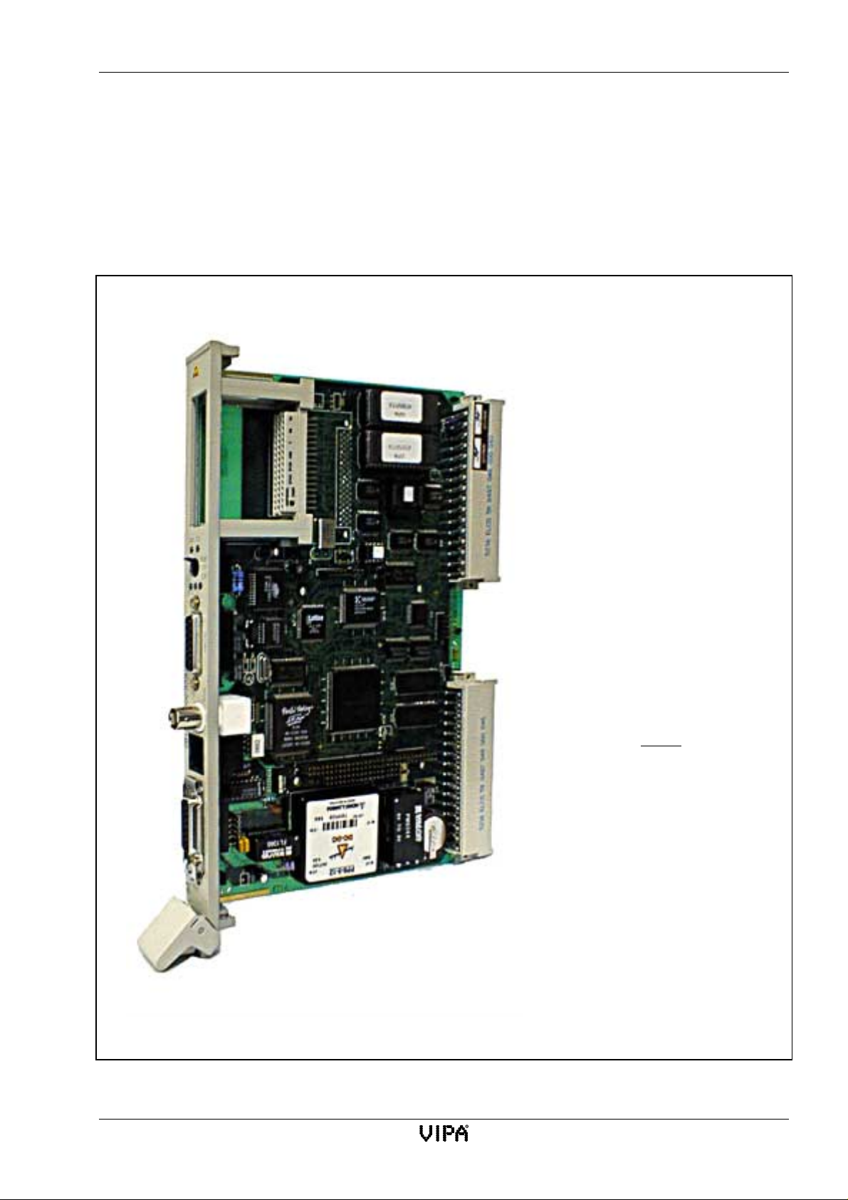
You may use the VIPA CP143plus or the CP143 TCP/IP to implement Industrial Ethernet H1 or
TCP/IP networks in your offices or factories.
The software used to configure the modules is compatible with MS-DOS, WINDOWS3.11,
WINDOWS95, WINDOWSNT and OS/2.
VIPA offers the following packages:
CP143plus
CP143-module
with H1-protocol
(Order-No.:VIPA SSN-BG81A)
CP143 TCP/IP
CP143-module
with TCP/IP-protocol
(Order-No.:VIPA SSN-BG89A)
Both are delivered with the same
configuration software and the
same manual.
The specific requirements are
covered by a single hardware platform which differs only in the
contents of the firmware.
The following passages refer to
the hardware as
"CP143 H1 / TCP/IP"
Fig. 1-1:Construction of the CP143 H1 or TCP/IP
Rev. 00/07 1-3
Page 14

Operation CP143 H1 / TCP/IP manual
1.3 Operation
The CP143 H1 / TCP/IP communication module is installed directly into the central processor or
into the respective expansion unit. The module contains four interfaces:
• Interface for the LAN cable via a transceiver (AUI, DIX)
• Interface for the LAN cable via thin ethernet cable
• Interface for the LAN cable via RJ45-socket (twisted pair)
• Interface for compatibility with the programmer or a DIN interface for configuration
purposes
The CP143 H1 / TCP/IP communication processor conducts the transfer of data via the cellular
network independently and relieves the CPU of this task. This operation covers the entire ISO-OSI
level model.
The VIPA CP143 H1 / TCP/IP module is controlled by the standard handler modules of the
installed PLC.
The following modules are required for interfacing with the VIPA CP143 H1 / TCP/IP:
SEND ALL, RECEIVE ALL, SYNCHRON, SEND DIREKT, RECEIVE DIREKT, FETCH.
These function modules can be used to transfer DB/DX-modules with a maximum length of
4096 DW. These function modules can be configured directly or indirectly.
Special features
• The CP143 H1 / TCP/IP communication processor is supplied complete with a 12V power
supply for the transceiver.
• The application of these modules does not require any hardware or software manipulation.
• Comes complete with thin ethernet interface.
• Contains a LED status indicator to display the operating status of the module and the
network.
1.4 Construction
• 80486 SLC 33 MHz CPU
• 1MBmainmemory
• Siemens CP1430 compatible programmer interface
• EPROM socket for EPROMs
• 4 KB Dual-Port-RAM as CP interface
• DIN interface for the PLC
• AUI interface (IEEE 802.3) for the LAN cable via a transceiver, RJ45 signal may be
connected to the AUI socket (Siemens compatible)
• RJ45 connector for ethernet
• Thin ethernet (BNC)
1-4 Rev. 00/07
Page 15

2 Communication protocols
2.1H1protocol 2-1
2.1.1 Structure of Industrial Ethernet H1 2-1
2.1.2 Operation 2-2
2.1.3 Structure and operation of the PLC interface 2-2
2.2 TCP/IP protocol 2-3
2.2.1 ISO-OSI level model 2-3
2.2.2 TCP/IP principle of operation 2-7
2.2.3 TCP/IP services 2-7
Page 16

Lerrzeichen
Page 17

CP143 H1 / TCP/IP manual Communication protocols
2 Communication protocols
2.1 H1 protocol
The Industrial Ethernet H1 LAN provides the basis for the implementation of large, high-tech,
decentralized automation systems. Industrial Ethernet H1 is the complete solution for the
implementation of large, open networks between the different departments of a company.
Compatible devices include:
• PLCs 115, 135, 150, 155
• programmers PG 685, PG 730, PG 750, PG 770
• computers
• other PLCs
The Industrial Ethernet H1 LAN may be used in the following applications:
• central control and supervision of production lines
• monitoring and communicating the status of machines
• management information
• production statistics
• the transfer of large amounts of data
• remote programming of PLCs
2.1.1 Structure of Industrial Ethernet H1
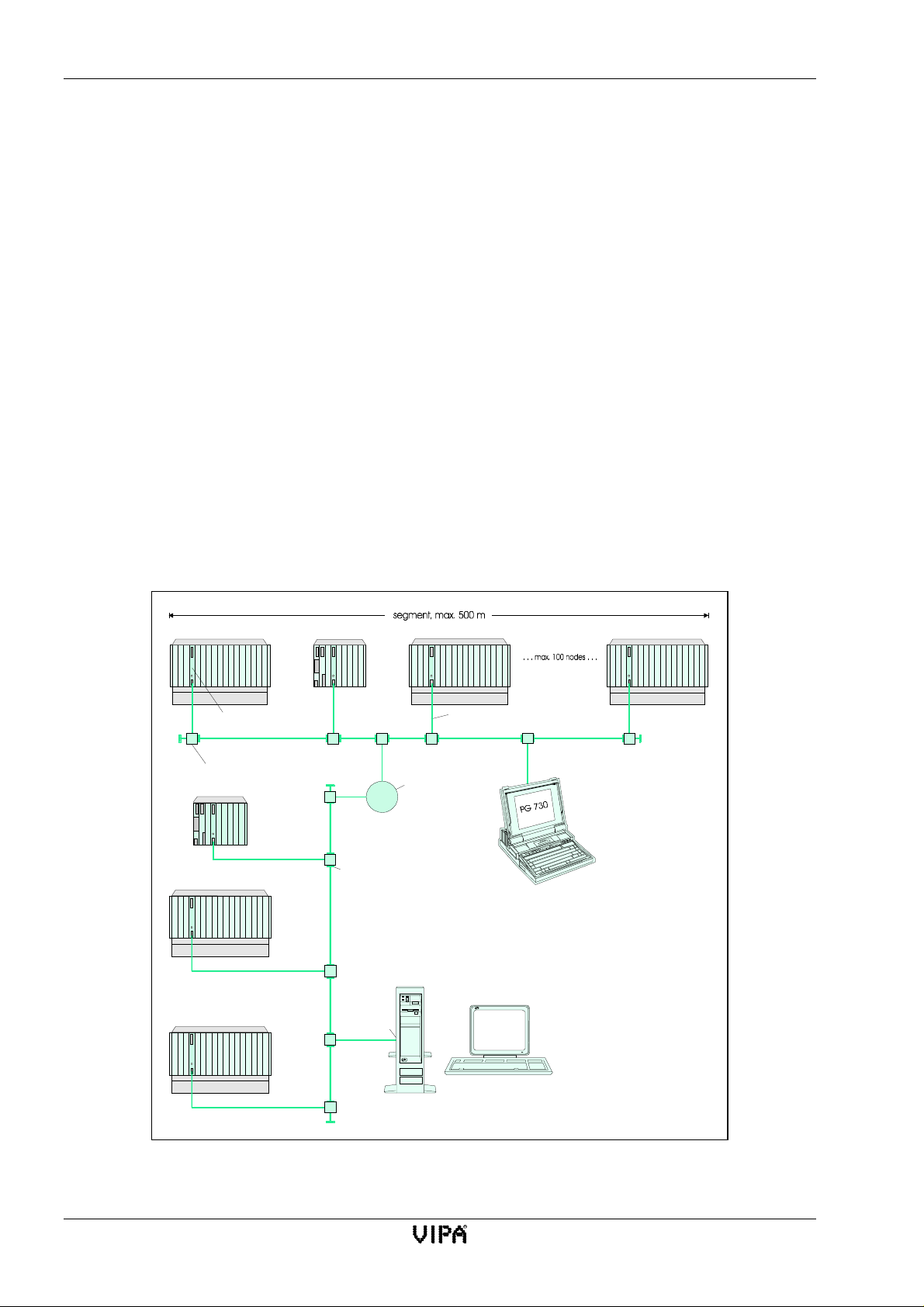
The Industrial Ethernet H1 LAN consists of separate segments. A single segment can support up to
100 terminal devices (PLCs, computers) and its length may be up to 500 m. Individual segments
may be linked by means of repeaters. A maximum of 2 repeaters may be placed between any two
terminal devices.
Repeaters may also be used to construct so-called remote-repeater-configurations. This combination
requires two repeaters and two additional Industrial Ethernet H1 transceivers.
The LAN cable may either be the triaxial cable (yellow cable) or the thin ethernet-cable
(cheapernet).
Triaxial cable:
All terminal devices or repeaters must be connected to the transceivers by means of a drop-cable
(plug-in cable 727-1) (max. length 50 m). The connection between the bus cable and the transceiver
is provided by coaxial plugs. A terminator is required at both ends of the bus cable.
A transceiver on the triaxial cable may be connected to a multiport repeater that can support up to 8
terminal devices.
Thin-Ethernet:
Terminal devices are connected directly to the cable, that is transceivers and drop-cables are not
required. The bus cable is connected to the module by means of BNC plugs. A terminator is
required at both ends of the bus cable.
Rev. 00/07 2-1
Page 18
H1 protocol CP143 H1 / TCP/IP manual
2.1.2 Operation
The Industrial Ethernet H1 LAN (in conformance with the Ethernet system standard) employs a
random access technique: every terminal device accesses the bus when required. Access to the bus
is co-ordinated by a CSMA/CD (Carrier Sense Multiple Access/Collision Detection) mechanism:
every terminal device “listens” on the LAN and accepts transmissions that match its own address.
Terminal devices can start a transmission only if the bus line is not engaged. Should two terminal
devices initiate a transmission simultaneously, they detect this event and stop transmitting. After a
random delay time they will restart the aborted transmission.
The programmers PG 685, PG 730, PG 750 and PG 770 may be connected directly to the Industrial
Ethernet H1 by means of a transceiver. You may then remotely modify the program of any PLC that
is connected to the LAN. The 923C co-ordinator or the programming multiplexer can also be used
to program a number of modules via a single connection.
The user services of LEVEL 4/4a (handler modules or libraries for PC-modules) are also available.
2.1.3 Structure and operation of the PLC interface
A dual-port RAM connects the CP143 H1 / TCP/IP directly to the back plane bus-LAN. At the PLC
the dual-port RAM is available as a standard-CP-interface with 4 tiles. Any H1 data traffic is
conducted via standard handler modules (SEND and RECEIVE).
Node (station)
Transceiver
CP143plus
Coaxialplug
CP1413plus
Repeater
connection cable 727-1
(max. 50m)
PC
per segment
Fig. 2-1:Example for the cabling of the Industrial Ethernet H1 LAN
2-2 Rev. 00/07
Page 19
CP143 H1 / TCP/IP manual Communication protocols
2.2 TCP/IP protocol
The TCP/IP protocol was an integral component of the Berkeley UNIX version 4.2 and as such it
became a de-facto standard in local-area networks. Many manufacturers of workstations have since
opted for the ethernet - TCP/IP -UNIX combination. All hardware systems that are currently of
importance support versions of the TCP/IP protocol. This applies equally to the low-end PC, the
typical mini-computer, right through to mainframe computers (the TCP/IP protocol has been
implemented on IBM systems as well) and also to special purpose computers like vector processors
and parallel processors. It is for this reason that TCP/IP is often used when heterogeneous systems
must be linked.
Using TCP/IP it has become possible to implement comprehensive open networks linking different
departments within an organization.
The following tasks may be solved by means of a TCP/IP bus system:
• central control and monitoring of manufacturing facilities
• transfer of the status of machines
• management information s ervices
• production statistics
• the transfer of large amounts of data
2.2.1 ISO-OSI level model
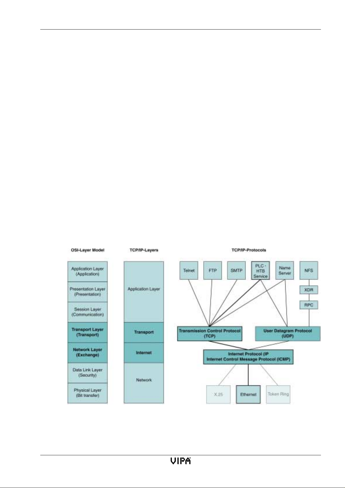
Level
7
6
5
4
3
2
1
Fig. 2-1:ISO-OSI level model
Rev. 00/07 2-3
Page 20

TCP/IP protocol CP143 H1 / TCP/IP manual
2.2.1.1 General
The ISO-OSI level model is based upon a suggestion that was developed by the International
Standards Organization (ISO). It represents the first step in the direction of an international standard
for the different protocols currently in use. The model is referred to as ISO-OSI level model. OSI is
the abbreviation for Open Systems Interconnection, that is communication between open systems.
The ISO-OSI level model is not a network architecture as the services and the protocols used on the
different levels have not been defined. The model simply provides information about the task that
each level must perform.
2.2.1.2 Description of the different levels
Level 1 Physical level (bit-transfer level)
The physical level transfers data bits via a communication channel. This level is generally
responsible for the mechanical, electrical and procedural interfaces and for the physical
communication medium that is used by the physical level:
• the voltages representing a logical 0 and a logical 1.
• the duration for which the voltage must be present to represent a valid bit.
• establishes a connection and terminates it when necessary.
• pin-allocation for the respective interface.
Level 2 Data link layer
The data link layer converts raw data into a data series ready for transfer. This is where the frame
delimiters are inserted during transmission and where they are detected during reception. This is
achieved by inserting a special bit-pattern at the start and at the end of a frame. In many instances a
flow-control and error detection mechanism is integrated into the data link layer.
Level 3 Network layer
The network layer is concerned with the selection of the packet path between the source and the
destination (other networks as well). Paths may be hard-wired in the network. They may also be
dynamic, that is they may be determined on the fly for every packet in order that the load on the
network optimized. The network layer must also ensure that different packets do not interfere with
each other. This layer is responsible for administrative functions for the transferred data, that is
counting of packets, characters or bits, etc.
The network layer must have the capacity to perform these tasks so that users of heterogeneous
networks may communicate with each other.
Level 4 Transport layer
The purpose of the transport layer is to accept data from the session layer, then to divide it up into
smaller portions, transfer this data to network layer and to ensure that every item arrives properly at
the destination. The transport layer generates a unique network connection for every transport link
required by the session layer. The transport layer determines the type of service that is provided to
the session layer. It can also increase the throughput, establish multiple network connections and
assign the data to these connections.
In addition to managing the use of multiple access channels by many message streams the transport
layer must also administer connections that the network establishes and relinquishes.
2-4 Rev. 00/07
Page 21

CP143 H1 / TCP/IP manual Communication protocols
Level 5 Session layer
The session layer provides the links that enable users of different systems to communicate. In
addition to the standard transport services the session layer also provides high-level services that
may be useful for certain applications. One of these services the control of interactive functions. The
session layer administers the flow of data where data can only be transferred in one direction
(similar to the token-management). A session can provide user-access to other systems or it can
transfer a file from one system to another.
Another service of the session layer is that of synchronization. Certain reference points are
superimposed on the data stream. If the network should crash it is only necessary to re-send the data
from the most recent reference point.
Level 6 Presentation layer
The presentation layer executes those functions that are used very often and therefore justify a
general procedure. This level is also responsible for the syntax and semantics of the transferred data.
One example of the services provided by the presentation layer is the co-ordination of data in a
standard and pre-arranged manner. The presentation layer converts the different data structures and
codes supplied by the various computers into a standard network code so that the users of these
computers may communicate.
Level 7 Application layer
The application layer supports a large number of protocols.
This layer provides various file-transfer and data processing functions to the user. The application
layer also adapts editor programs to the requirements of the respective terminal equipment.
Different file processing systems employ different conventions for file names and different methods
to display lines of text, etc. You must remember these properties when you transfer files between
different systems. This function as well as electronic mail, remote task entry and directory inquiries
are also part of the services provided by the application layer.
Rev. 00/07 2-5
Page 22

TCP/IP protocol CP143 H1 / TCP/IP manual
2.2.1.3 TCP/IP in relation to the ISO-OSI level model
TCP/IP is older than the ISO-OSI level model. For this reason the different layers can not be applied
directly to TCP/IP. The TCP/IP network layers correspond to level 1 and 2 of the ISO-OSI model.
Levels 5 and 6 of the ISO-OSI model are already integrated into the protocols of the TCP/IP
application layer.
Internet Protocol (IP)
The purpose of the internet protocol IP is to transport packets of data from a sender to a receiver via
a number of interlinked networks. It may thus be compared with level 3 of the ISO-OSI level model.
IP data transfer services are not protected and do not require a direct connection. The main IP
services are: the transfer of datagrams via a multitude of interconnected networks, to address the
respective partner correctly, to divide data packets according to the respective network conventions
and to reassemble them, and to transfer information about the sequence of packets and their security
characteristics.
Transmission Control Protocol (TCP)
The transmission control protocol TCP is intended to provide a reliable transport-end-to-endconnection between two different systems. For this reason TCP may be compared to level 4 of the
ISO-OSI level model and it interfaces directly with the internet protocol IP.
TCP provides the following essential services:
• Orientation towards a connection
• Guaranteed sequences
• Loss detection
• Connection time-out detection
• Multiplexing
• Flow control
• Transparent data transfers
• The secure establishment and termination of connections
User Datagram Protocol (UDP)
This protocol can also be classed with level 4 of the ISO-OSI level model and interfaces directly
with the internet protocol IP. This protocol does not make use of connections or error correction for
network transfers. It also does not expect acknowledgements from the receiver of the data.
2-6 Rev. 00/07
Page 23

CP143 H1 / TCP/IP manual Communication protocols
2.2.2 TCP/IP principle of operation
TCP and IP are only two of the many protocols required for the establishment of a complete
network architecture. The application layer of the computer supplies programs like FTP and Telnet.
The standard handler modules of the program define the application layer of the CP143 TCP/IP.
These application programs use the transport layer and the TCP or UDP protocols to transfer data,
and these protocols communicate with the IP protocol of the internet layer.
The main task of the IP is to address data packets properly. This means that the IP functions like an
envelope. The network determines the destination of the data packet by means of the address and
uses this to route the packet accordingly. The protocol divides data into smaller units as different
networks may require different length data frames. A number is assigned to every packet so that
received packets may be acknowledged and to allow for reassembly of the original data. TCP as
well as IP have their own envelope where they store the required numbers so that these sequence
numbers can be transferred via the network. A packet of data is inserted into a TCP-envelope. This
is then inserted into an IP envelope and transmitted via the network. On the network, TCP is
responsible for the safe transport of data. TCP can recognize and correct transmission errors. These
error detection and correction systems ensure that TCP connections are relatively safe. However, in
this case UDP is much faster. It neither detects missing data packets nor does it check the sequence
of the packets. UDP is an unprotected protocol.
2.2.3 TCP/IP services
OPEN / CONNECT
In an active situation this opens a virtual connection with a partner. In a passive situation this waits
for a connection from a partner.
SEND
Transfer of a data buffer to TCP for transmission to a partner.
RECEIVE
Reception of data from a partner.
CLOSE
Termination of a connection.
Rev. 00/07 2-7
Page 24

TCP/IP protocol CP143 H1 / TCP/IP manual
2-8 Rev. 00/07
Page 25

3 Network planning
3.1 Ethernet network-terminology 3-1
3.2 Thin-ethernet-cable networks 3-3
3.2.1 Thin-ethernet-cable network-layout 3-5
3.2.2 Regulations and specifications 3-6
3.2.3 Technical data thin-ethernet 3-7
3.3 Thick-ethernet-cable networks 3-8
3.3.1 Thick-ethernet-cable network-layout 3-10
3.3.2 Regulations and specifications 3-11
3.3.3 Technical data thick-ethernet 3-13
3.4 Combining thin/thick ethernet cable in networks 3-14
3.4.1 Combination of thin/thick ethernet cable hardware 3-14
3.4.2 Thin/thick ethernet cable combination network-layout 3-15
3.5 Twisted Pair 3-16
3.5.1 Twisted pair-cable network-layout 3-16
3.6 Planning a network-layout 3-18
3.7 Standards and specifications 3-19
Page 26

LerrzeicLerrzeichenhen
Page 27
CP143 H1 / TCP/IP manual Network planning
3 Network planning
3.1 Ethernet network-terminology
An ethernet network provides a communication link between different stations on the network. The
stations on the network may consist of personal computers, industrial computers, automation
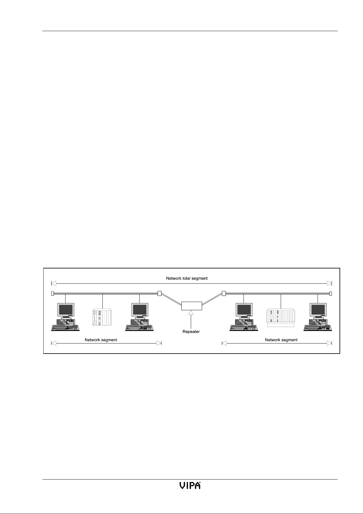
equipment etc. Stations are connected to the network and located a certain minimum distance from
each other. The stations on the network and the LAN cable form a network segment. (See Fig. 3-1).
The cable of the network segment usually consists of a number of network cables of varying length
that are linked by means of connectors.
The length of the network segment and the number of stations that may be connected to it is limited.
It is possible to extend a network segment by linking multiple segments via repeaters.
A repeater increases the physical topology of a network. The repeater requires two transceivers to
link two different segments to each other. In this case the repeater is transparent to the network and
combines the two segments into a single logical channel.
In this situation the repeaters task is to regenerate and to amplify the signals in both directions. It
must also be able to recognize, process and to communicate inter-segment collisions. Repeaters do
not possess a unique address and are therefore not accessible as they are invisible to the stations
connected to the network.
The overall network cable consists of the sum of all segment cables.
Fig. 3-1:Parts of an ethernet network
Rev. 00/07 3-1
Page 28

Ethernet network-terminology CP143 H1 / TCP/IP manual
Three types of ethernet cable exist:
• Thin-ethernet-cable (also called thin ethernet cable or Cheapernet-cable).
• Thick-ethernet-cable (also called thick ethernet cable or standard ethernet-cable or yellow-cable).
• Twisted pair-cable (telephone cable)
Thin ethernet-cable is far more economical than thick ethernet-cable. This applies to the cost of the
cable, the cost of installation and any additional hardware. It does, however, suffer from a higher
level of susceptibility for EMC interference. Connections to the thin ethernet-cable are provided by
BNC T-pieces.
Thick ethernet-cable consists of a thick yellow cable which is much like a pipe. The cable has
markings at a distance of 2,5 m which indicate the positions where a connection to the cable may be
attached.
These two types of network cable can be employed to produce in three different versions of ethernet
network:
1. a network using only thin ethernet cable
2. a network consisting only of thick ethernet cable and
3. a combination of these two
Under certain conditions you may also use twisted telephone twin-cable instead of the coaxial cable
(twisted pair).
Twisted pair cable consists of four insulated copper wires of 1 mm diameter that have been twisted
together in pairs.
In contrast to the coaxial ethernet networks which provide a type of bus-topology, the twisted pair
network is a point-to-point network. The resulting network has a star-topology. Every station is
coupled individually with a central hub to form the ethernet network.
3-2 Rev. 00/07
Page 29

CP143 H1 / TCP/IP manual Network planning
3.2 Thin-ethernet-cable networks
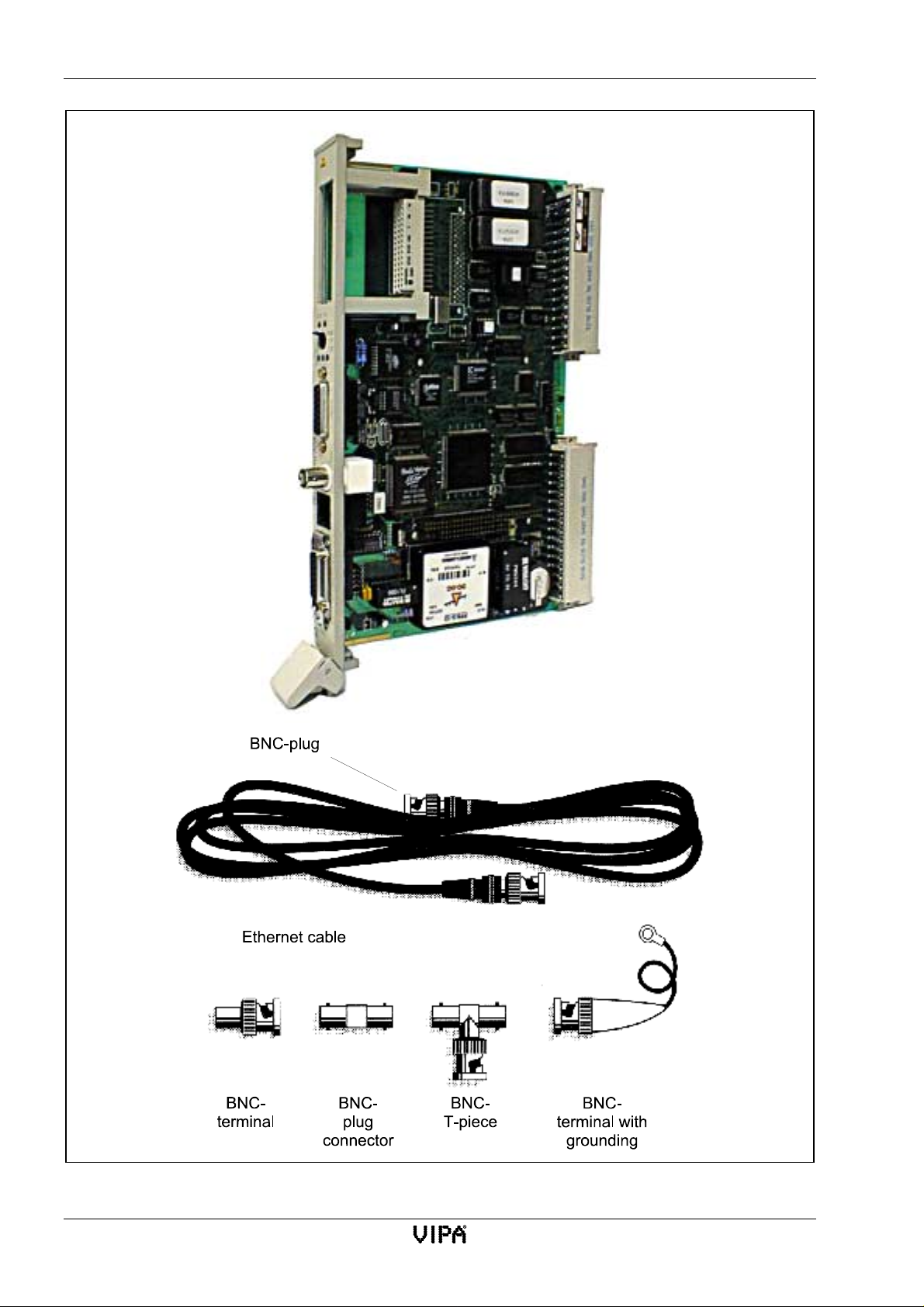
Thin-ethernet-cable network hardware
This chapter contains a description and an illustration (Fig. 3-2) of the hardware required for a thinethernet-network.
Network adapter
Network adapters are installed in every station on the network and linked by means of a
network cable to provide the communication medium between these stations.
BNC-connectors
BNC-plugs and -sockets provide the electrical link between the hardware on the
network. The network cable is connected to the BNC-socket located on the network
adapter. BNC-plugs connected to both ends of the network cable link the different
segments of the cable via a T-piece or a barrel connector. The T-piece is connected to
the BNC-socket on the network adapter.
Thin-ethernet-cable
Thin-ethernet-cable consists of RG-58A/U 50 Ohm coaxial cable with a diameter of 0,2
inch (5,08 mm).
BNC-connectors
BNC-connectors are used to interconnect two thin-ethernet network cables. Where two
portions of a thin-ethernet network must be linked these connectors have a distinct
advantage over T-pieces. You may obtain these BNC-connectors from VIPA GmbH.
BNC-T-pieces
The two sockets located at opposite ends of the T-piece provide the connection to the
BNC-connectors on the thin-ethernet cable. The third connector on the T-piece is
connected to the BNC-connector on the network adapter and provides the physical link
to the network. You may obtain BNC-T-pieces from VIPA.
BNC-terminator
Every network must end in a 50 Ω BNC terminator which acts as a matched load and
which reduces electrical interference on the network. The terminator is connected to one
of the two sockets of the T-piece when no other cable is connected. Some BNC
terminators have a ground connection which may be used to ground the screen of the
network cable. You may obtain BNC terminators with and without ground connection
from VIPA GmbH.
One side of a network s egment (it is immaterial which side) must be fitted with
a BNC-terminator which has a ground connection!
The other side of the segment may not have a terminator!
Rev. 00/07 3-3
Page 30
Thin-ethernet-cable networks CP143 H1 / TCP/IP manual
CP 143 H1 / TCP/IP
Fig. 3-2:Thin ethernet network hardware
3-4 Rev. 00/07
Page 31
CP143 H1 / TCP/IP manual Network planning
3.2.1 Thin-ethernet-cable network-layout
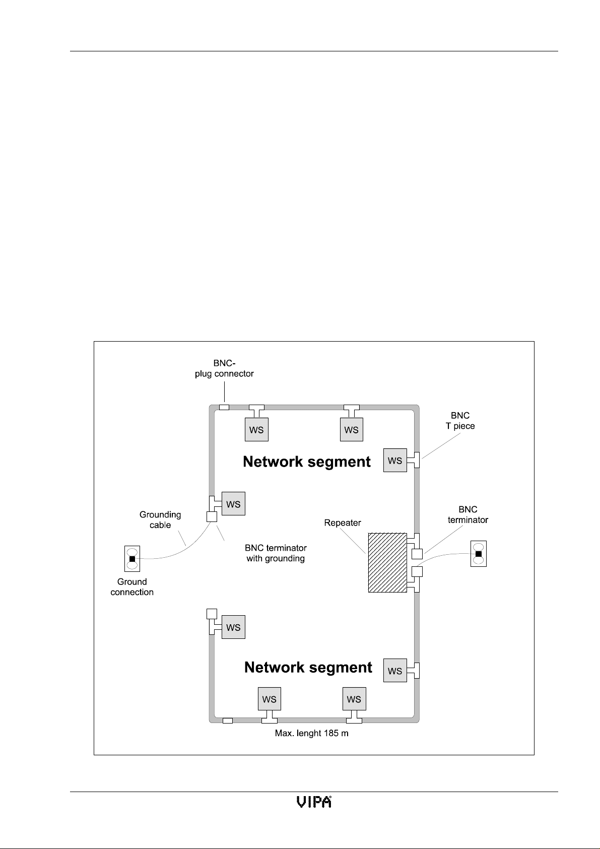
Here follows a summary of the restrictions and the rules that apply to a thin-ethernet-cable network.
Fig. 3-3 is an illustration of this summary.
Restrictions
• Maximum number of network segments:
• Maximum length of a network segment:
• Maximum total length of the network cable:
• Maximum number of network stations on a
segment:
• Minimum distance between two BNC-T-pieces:
5 (3 coaxial segments with network
stations and 2 interconnecting segments
without network stations)
185 m
925 m
30 (every repeater is counted as a station)
0,5 m
Fig. 3-3:Example for a thin-ethernet cable network
Rev. 00/07 3-5
Page 32

Thin-ethernet-cable networks CP143 H1 / TCP/IP manual
3.2.2 Regulations and specifications
Certain basic regulations must be observed when planning or installing a network:
• The cabling of a network consists of a number of segments. Each segment must be terminated
with its characteristic impedance (terminator) of 50 Ω.
• According to the ISO 8802.3 specification the maximum length of an individual segment is
185 m.
• Wherever possible, the network should consist a homogeneous segments of coaxial cable as
every connector introduces losses. When it becomes necessary to extend existing segments of
coaxial cable you should always use preconfigured cables. Please note that the maximum length
of a segment may not exceed 185 m.
• The screen of the coaxial cable may only be grounded at a single point on the entire cable. This
point must posses a defined low impedance. All other connectors and terminators must be
insulated from ground.
• Any two stations on the network may only have a single connection between them. Where
multiple physical paths exist the resulting interference will be interpreted as a signal and cause
collisions which may abort the data transfer.
• Single drop-cables are not permitted.
3-6 Rev. 00/07
Page 33

CP143 H1 / TCP/IP manual Network planning
Guidelines for the routing and installation of network components
• As a rule, a minimum distance of 1m is prescribed with respect to electrical equipment, cabling
and other components that could produce electromagnetic and electrostatic fields. This includes
parallel runs of power or high-tension cables, circuit breakers etc.
• The ISO-specifications allow for a maximum field strength of 2 V/m at frequencies between 10
kHz and 30 MHz and 5 V/m at frequencies between 30 MHz and 1 GHz.
• Once a coaxial cable segment and all its components have been installed it is essential that the
worst-case reflections on the cable are determined. These should never exceed 7% of the injected
amplitude of the original signal. The reflection coefficient can be checked by means of a
reflectometer.
• The overall loop resistance of a coaxial cable segment together with all its plugs and connectors
may not exceed a maximum of 4Ω.
• The minimum radius of any bend in the cable may not be less than 5 cm. When multiple bending
is anticipated the radius must not be less than 8 cm.
3.2.3 Technical data thin-ethernet
Coaxial cable
Impedance
Attenuation
Propagation
Minimum radius for bends,
single bend
Minimum radius for bends,
multiple bends
Diameter of center
conductorsolid copper
50 Ω±2 Ω
≤ 18 dB/km for a 10 MHz sine wave
≤ 12 dB/km for a 5 MHz sine wave
≥ 0,77 c (velocity of light)
5cm
8cm
0,89 mm ± 0,05 mm
Outside diameter for
4,9 mm
polyvinylchloride (PVC)
Outside diameter for
4,8 mm
fluorpolymer
Rev. 00/07 3-7
Page 34

Thick-ethernet-cable networks CP143 H1 / TCP/IP manual
3.3 Thick-ethernet-cable networks
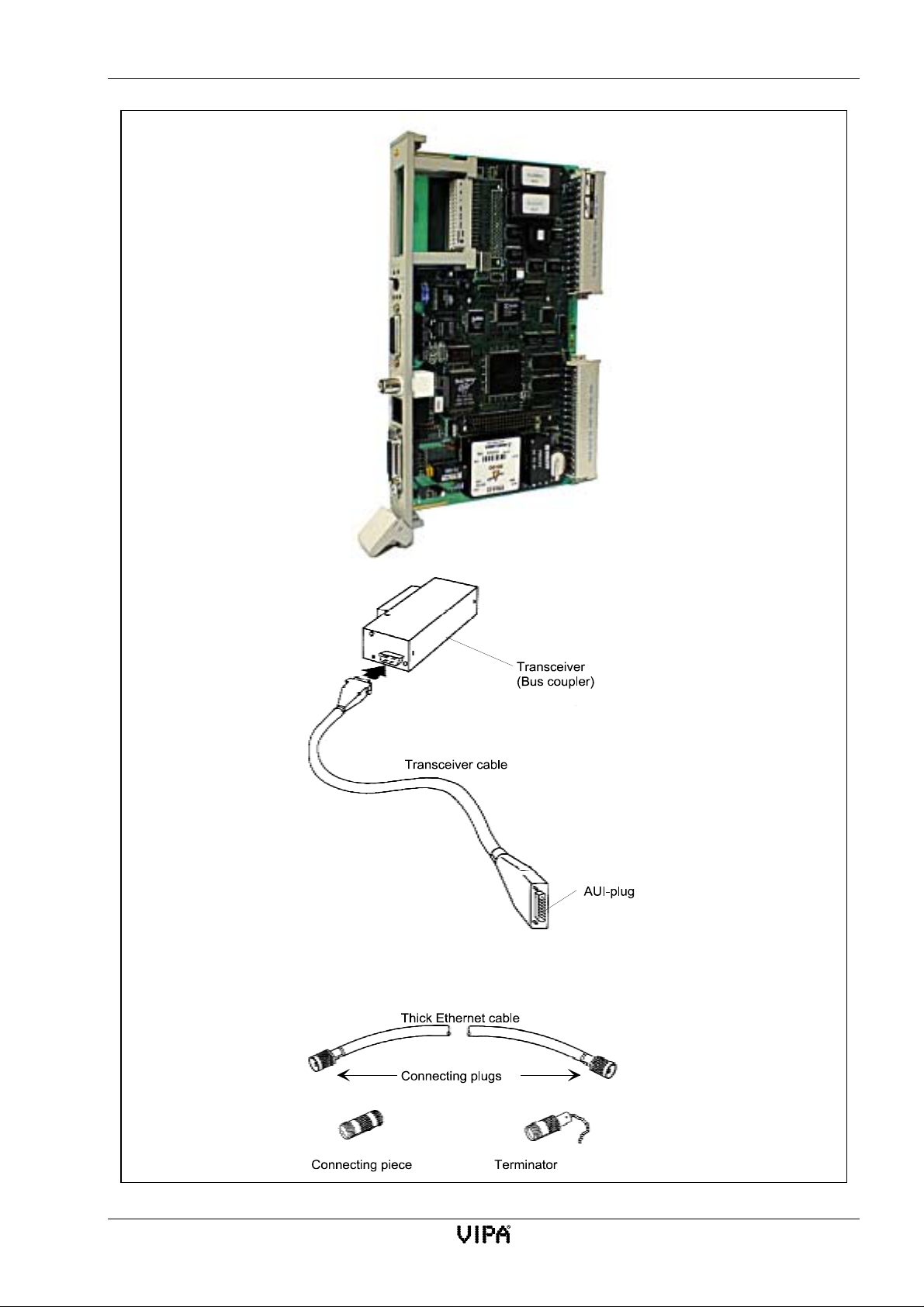
Thick-ethernet-cable network hardware
This chapter contains a description and an illustration (Fig. 3-4) of the hardware required for a
thick-ethernet-network.
Network adapter
Network adapters are installed in every station on the network and linked by means of a
network cable to provide the communication medium between these stations.
Transceiver
The stations on a thick-ethernet cable communicate via an external transceiver which is
attached to the network cable. External transceivers are required when a thick-ethernet
cable is used as communication medium.
Transceiver-cable
The transceiver-cable (drop-cable) connects the station (network adapter) to the external
transceiver.
AUI-connector
The end of a transceiver cable is terminated in an AUI (DIX) plug or an AUI-socket.
The AUI-plug is connected to the network adapter located in a station. The AUI-socket
is connected to the external transceiver.
Thick-ethernet-cable
The thick-ethernet-cable consists of a 50 Ohm coaxial cable with a diameter of 0,4 inch
(10,16 mm). Different lengths of this cable are available complete with standard 0,4
inch N-type plugs at each end. The cable may be obtained from any reputable cabling
supplier.
N-type plug
An N-type plug is attached to each end of the thick-ethernet cable.
N-type connector
N-type connectors are used to connect two thick-ethernet cables together.
N-type-terminator
An N-type 50 Ω termination resistance “terminates” the network and prevents electrical
interference from the network. This is attached to the N-type socket of the transceiver
that is not connected to another cable. Certain terminators are provided with a grounding
strap to connect the screen of the network cable to ground.
One side of a network s egment (it is immaterial which side) must be fitted with
a terminator which has a ground connection!
The other side of the segment may not have a terminator!
3-8 Rev. 00/07
Page 35
CP143 H1 / TCP/IP manual Network planning
CP 143 H1 / TCP/IP
Fig. 3-4:thick-ethernet network hardware
Rev. 00/07 3-9
Page 36
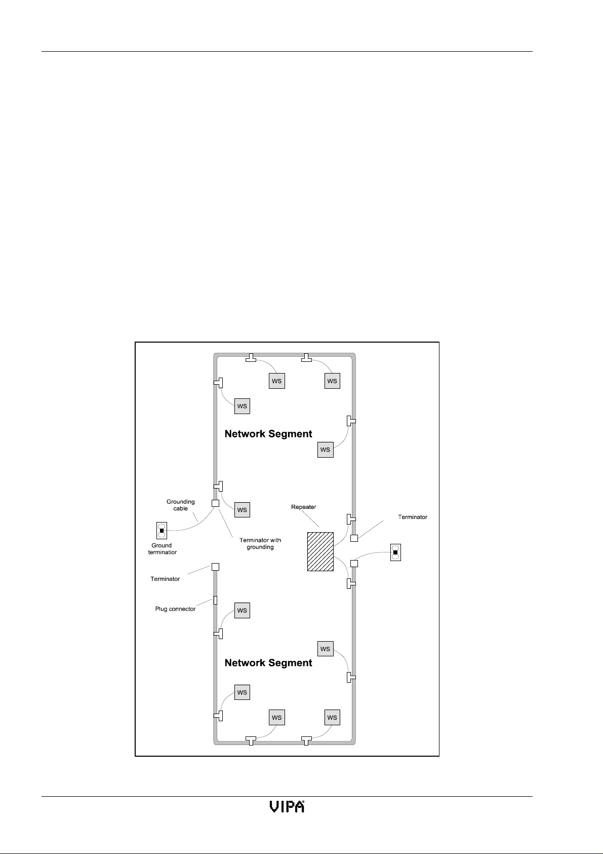
Thick-ethernet-cable networks CP143 H1 / TCP/IP manual
3.3.1 Thick-ethernet-cable network-layout
Here follows a summary of the restrictions and the rules that apply to a thick-ethernet-cable
network. Fig. 3-5 is an illustration of this summary.
Restrictions
• Maximum number of network segments:
• Maximum length of a network segment:
• Maximum total length of the network cable:
• Maximum number of network stations on a
segment:
• Minimum distance between two transceivers:
• Maximum length for a transceiver cable:
5 (3 coaxial segments with network
stations and 2 interconnecting segments
without network stations)
500 m
2.500 m
100 (every repeater is counted as a station)
2,5 m
50 m
Fig. 3-5:Example for a thick-ethernet network
3-10 Rev. 00/07
Page 37

CP143 H1 / TCP/IP manual Network planning
3.3.2 Regulations and specifications
Certain basic regulations must be observed when planning or installing a network:
• The cabling of a network consists of a number of segments. Both ends of each segment must be
terminated with its characteristic impedance (terminator) of 50 Ω.
• According to the ISO 8802.3 specification the maximum length of an individual segment is
500 m.
• Any segment may consist of a number of different parts. In this case you must ensure that the
length of each part is an odd multiple of 23,4 m to eliminate reflections at the joints and the ends
of any portion of the cable.
• The length of any part may thus be calculated as follows:
TSL = (2n + 1) * 23,4 m; N = 0, 1, 2, 3...
• Wherever possible, the network should consist of a homogeneous segments of coaxial cable as
every connector introduces losses. When it becomes necessary to extend existing segments of
coaxial cable you should always use standard portions of the cable. Please note that the
maximum length of a segment may not exceed 500 m.
• The screen of the coaxial cable may only be grounded at a single point on the entire cable. This
point must posses a defined low impedance. All other connectors and terminators must be
insulated from ground.
• Any two stations on the network may only have a single connection between them. Where
multiple physical paths exist the resulting interference will be interpreted as a signal and cause
collisions which may abort the data transfer.
• Single drop-cables are not permitted.
Rev. 00/07 3-11
Page 38

Thick-ethernet-cable networks CP143 H1 / TCP/IP manual
Guidelines for the routing and installation of network components:
• As a rule, a minimum distance of 1m is prescribed with respect to electrical equipment, cabling
and other components that could produce electromagnetic and electrostatic fields. This includes
parallel runs of power or high-tension cables, circuit breakers etc.
• The ISO-specifications allow for a maximum field strength of 2 V/m at frequencies between 10
kHz and 30 MHz and 5 V/m at frequencies between 30 MHz and 1 GHz.
• Once a coaxial cable segment and all its components have been installed it is essential that the
worst-case reflections on the cable are determined. These should never exceed 7% of the injected
amplitude of the original signal. The reflection coefficient can be checked by means of a
reflectometer.
• The overall loop resistance of a coaxial cable segment together with all its plugs and connectors
may not exceed a maximum of 5Ω.
• The minimum radius of any bend in the cable may not be less than 21 cm. Where multiple
bending is anticipated the radius must not be less than 40 cm.
3-12 Rev. 00/07
Page 39

CP143 H1 / TCP/IP manual Network planning
3.3.3 Technical data thick-ethernet
Coaxial cable
Impedance
Impedance linearity
Inductivity 0,21 µH/km
Capacity
Attenuation
Propagation
Loop resistance
Minimum radius for bends, single bend 21 cm
Minimum radius for bends, multiple bend 40 cm
Diameter of center conductor
solid copper
Thickness of the dielectric 1,99 mm
Thickness of the screen
Screening effectiveness
50 Ω±2 Ω
± 3 Ω with a period > 2 m
85 pF ± 5pF
≤ 18 dB/km for a 10 MHz sine wave
≤ 12 dB/km for a 5 MHz sine wave
≥ 0,77 c (velocity of light)
≤ 10 m Ω/m at 20° C
2,17 mm ± 0,013 mm
1,06 mm ± 0,089 mm
≥ 92 %
Thickness of the outer insulator
Outside diameter for polyvinylchloride (PVC)
Outside diameter for fluorpolymer
Transceiver cable
Maximum operating voltage 30 V
Maximum current capacity 2,8 A
Capacity of a single pair of lines 55 pF/m
Impedance
Screening effectiveness 78 %
Maximum attenuation 3 dB / 50 m
The yellow outer cover of the cable bears imprinted marks at a distance of 2,5 m ± 5cm.These
marks indicate the positions where a transceiver may be connected. The coaxial connectors at the
end of every cable are N-type plugs.
1,25 mm ± 0,089 mm
10,287 mm ± 0,178 mm
9,525 mm ± 0,178 mm
78 Ω±5 Ω
Rev. 00/07 3-13
Page 40
Combining t hin/thick ethernet cable in networks CP143 H1 / TCP/IP manual
3.4 Combining thin/thick ethernet cable in networks
It is possible to combine thin-ethernet and thick-ethernet cabling in a single network.. The lower
price of the thin-ethernet cable may provide a more cost-effective solution than a system that is
purely based on thick-ethernet cable.
When thick-ethernet cable is used to link repeaters the distance may be substantially larger than if
the link was provided by a thin-ethernet cable.
You may use one of the two methods below to establish a network that combines thick and thinethernet cable:
• Connecting the thin-ethernet cable segment to a network based on thick-ethernet cable via
a repeater. It is possible to combine a maximum of five unlike network segments (using
four repeaters) in this manner.
• It is also possible to use thin and thick-ethernet cables within the s ame network segment.
The structure of such a network is described below under the heading “Combination
thin/thick ethernet cable hardware".
3.4.1 Combination of thin/thick ethernet cable hardware
Networks that use a combination of thin and thick ethernet cable employ the network hardware as
the individual thin-ethernet and the thick-ethernet networks would if they are not combined. It is
however necessary to include adapters that provide the interconnection between the different types
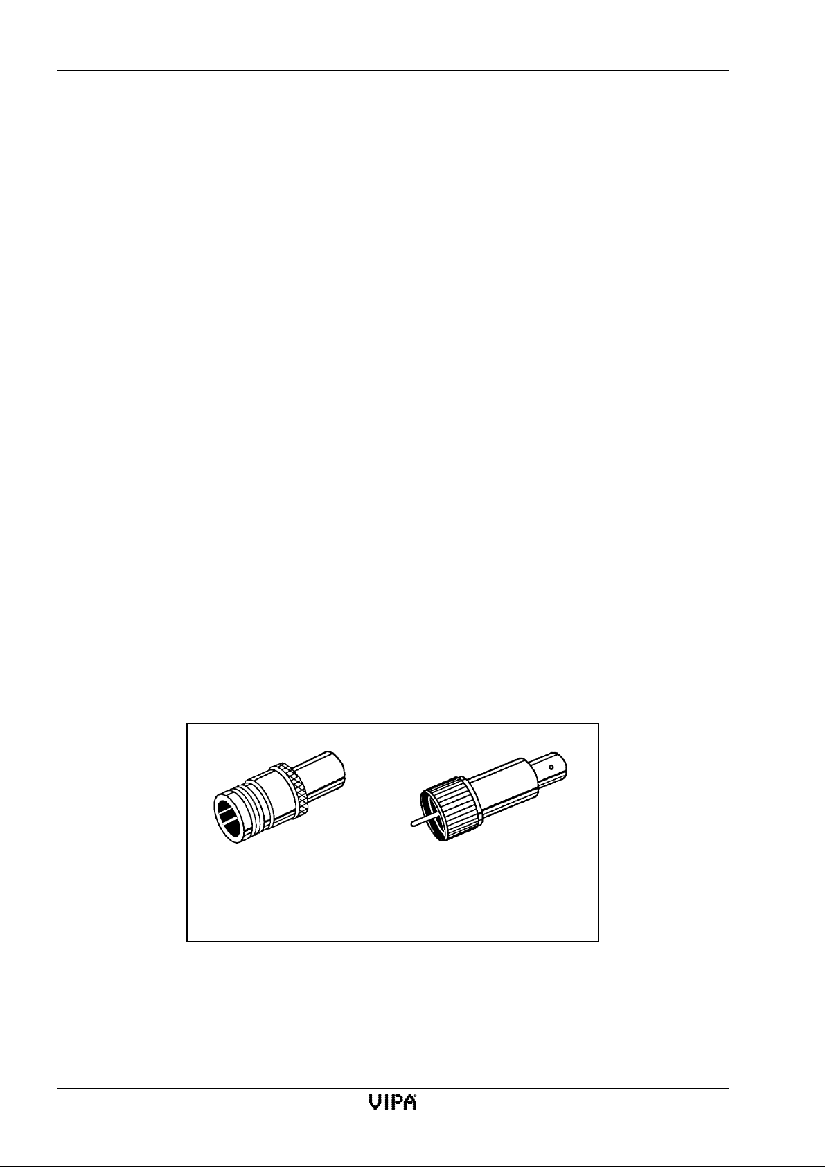
of cable. Fig. 3-6 shows two such adapters.
• N-type jack to BNC-jack
• N-type plug to BNC-plug
Thick Ethernet jack
on
BNC jack
Thick Ethernet plug
on
BNC plug
Fig. 3-6:Adapters for linking unlike segments
3-14 Rev. 00/07
Page 41
CP143 H1 / TCP/IP manual Network planning
3.4.2 Thin/thick ethernet cable combination network-layout
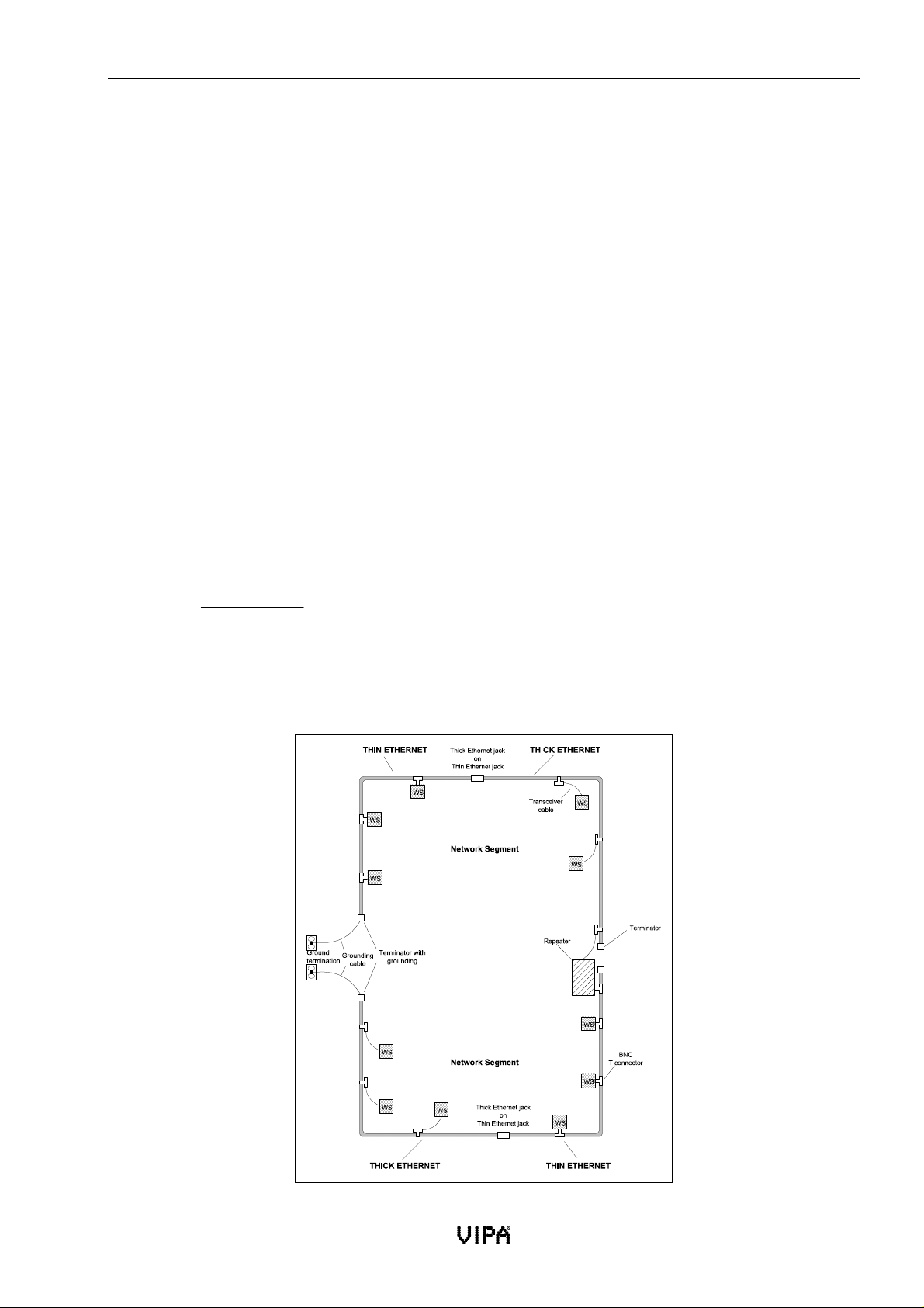
This chapter describes a method of combining thin ethernet cable and thick ethernet cable in a
single network segment. This method employs as much thin ethernet cable as possible. Fig 2-7
illustrates this technique of combining thin and thick ethernet cable.
The length of a network employing a combination of thin and thick ethernet cable may be between
185 m and 500 m. In this case the minimum length has been specified as 185 m as shorter segments
can consist entirely of thin ethernet cable. The maximum length of 500m is determined by the
physical limitations of the thick ethernet cable.
You may use the following equation to calculate the maximum length of the thin ethernet cable in a
combination network:
500
mL
328
.
(L = length of network segment that must be implemented
t = maximum length of the thin ethernet cable)
e.g. you must implement a network segment of 457 m and reduce the cost of the network hardware
to a minimum. You would use the equation above to determine the maximum length of the
thin ethernet cable as follows.
t−=
500 457
mm
−
328
131
=.,
m
You may thus use up to 13,1 m of the cost-effective thin ethernet cable. For the remainder of 443,9
m of the network segment you must use thick ethernet cable.
Please note: you can interconnect up to 5 different network segments!
Fig. 3-7:Example of a network combining thin and thick ethernet cable
Rev. 00/07 3-15
Page 42
Twisted Pair CP143 H1 / TCP/IP manual
3.5 Twisted Pair
Twisted Pair network hardware
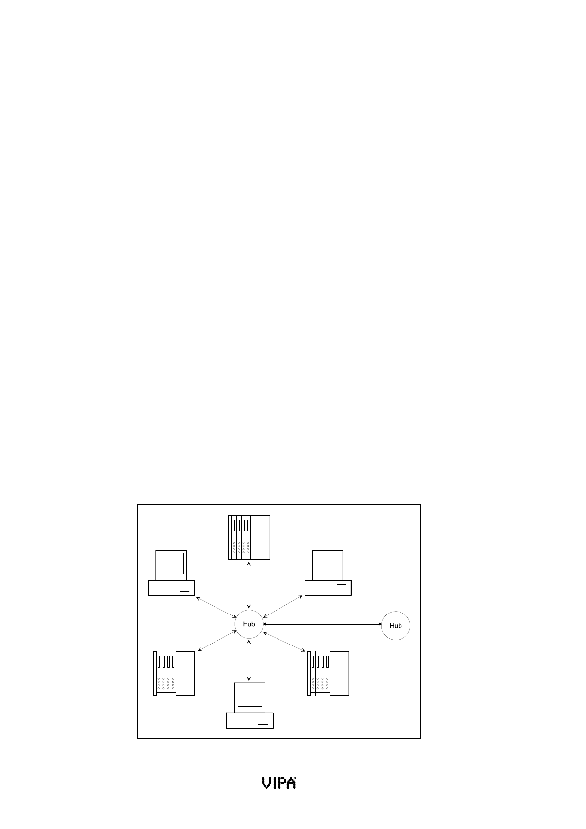
A twisted pair-network can only have a star-type configuration. This topology requires a
hub that supports the star-type configuration.
The following paragraphs contain a description of the hardware required for
implementing a twisted pair network.
Network adapter
The network adapter which is installed in every station on the network provides the
interface that allows every station to communicate with every other station..
Hub (star-type configuration)
The Hub is the central element that provides the facilities required to implement an
ethernet network using twisted pair cable. Every station is connected directly to the hub
to form the ethernet network. A hub operates like a repeater. It may be interfaced with
thin or thick ethernet cable.
Twisted pair-cable
The twisted pair cable consists of a four-core cable where the cores are twisted together
in pairs. The conductors have a diameter between 0,4 and 0,6 mm.
3.5.1 Twisted pair-cable network-layout
Here follows a summary of the restrictions and the rules that apply to twisted pair networks
Restrictions
• Maximum number of hubs per segment: 2
• Maximum segment length: 100 m
Fig. 3-8:Star topology of a twisted pair network
3-16 Rev. 00/07
Page 43
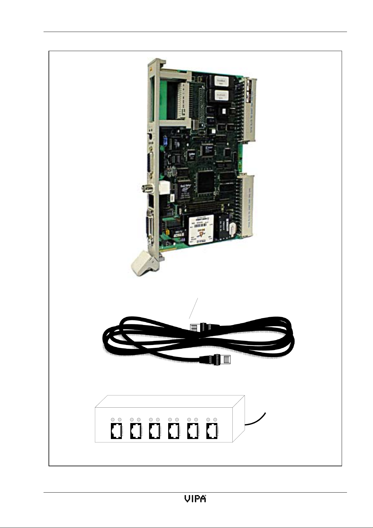
CP143 H1 / TCP/IP manual Network planning
Twisted pair cable
Star coupler (Hub)
12
Rx Tx Rx Tx Rx
Tx
Twisted pair plug
Power
3
456
Rx Tx Rx
Tx
Rx
Tx
supply
Fig. 3-9:Twisted pair network hardware
Rev. 00/07 3-17
Page 44

Planning a network-layout CP143 H1 / TCP/IP manual
3.6 Planning a network-layout
At this point you are aware of the limitations of the different cabling systems, and you can provide
answers to the following questions with respect to the network that you have to implement:
Determination of network requirements
• What is the extent of the coverage of the proposed network?
• What is the optimum number of network segments required to satisfy the physical (space,
interference) conditions applicable to the proposed system?
• How many network stations (H1 TCP/IP, IPC, PC, transceiver, possible bridges) should be
connected to the network?
• What is the distance between the different stations on the network?
• What is the expected increase in coverage and number of connections that the system must be
able to handle?
Drawing a plan of the network
Prepare a drawing of the plan of the network! Identify every item of hardware (like cables,
transceivers, amplifiers, termination resistors). Observe the rules and limitations that were outlined
in the previous chapters.
Measure the distance between all components to ensure that they are within the prescribed
parameters (min. distance, max. length...).
3-18 Rev. 00/07
Page 45

CP143 H1 / TCP/IP manual Network planning
3.7 Standards and specifications
The main characteristic of a LAN is that it provides a single physical communication path. The
physical communication medium may consist of:
• one or more electrical connections (twisted cables)
• coaxial cable (triaxial cable)
• fiber-optic cable
The communications between individual stations is subject to certain standards and rules that must
be met by every station on the network. These determine the form of the communication protocol,
the access method to the LAN and other basic principles that are important for communicating on
the network.
The VIPA H1-network was developed to satisfy the ISO standards and specifications.
The standards and specifications for networking systems were determined by international and
national committees.
ANSI American National Standards Institute
This body is currently busy formulating agreements for high-speed LANs (100 MB/s) based on fiberoptic technology in ANSI X3T9.5. (FDDI) Fiber Distributed Data Interface.
CCITT Committee Consultative Internationale de Telephone et Telegraph.
Amongst others, this advisory committee produces the specifications governing the interfacing of
industrial communication networks (MAP) and of office networks (TOP) to Wide Area Networks
(WAN).
ECMA European Computer Manufacturers Association.
generates the different standards for MAP and TOP.
EIA Electrical Industries Association (USA)
this committee determines standards like RS-232 (V.24) and RS-511.
IEC International Electrotechnical Commission.
This committee sets specific standards, e.g. those for the Field Bus.
ISO International Organisation for Standardization.
This association of national standards offices has determined the OSI-model (ISO/TC97/SC16).It
outlines the framework for the standards that are applicable to data communications. The ISO
standards are converted to the different national standards like UL and DIN.
IEEE Institute of Electrical and Electronic Engineers (USA).
The project group 802 determines LAN-standards for communication speeds from 1 to 20 MB/s. IEEE
standards are often the basis ISO-standards, e.g. IEEE 802.3 = ISO 8802.3.
The serial Industrial Ethernet H1 LAN is an open communication system that can be used for the
exchange of data between all devices that comply with a set of common rules. These devices may
also include units manufactured by other companies.
Data is communicated on the basis of the OSI ISO-reference model. This model provides the
specifications for all the processes, rules and the strategy for common data communications.
Rev. 00/07 3-19
Page 46

Standards and specifications CP143 H1 / TCP/IP manual
3-20 Rev. 00/07
Page 47

4 The CP143 H1 / TCP/IP network board
4.1 The construction of the module 4-1
4.1.1 Components of the module 4-2
4.1.2 Jumper settings 4-3
4.1.3 Sockets and plugs 4-5
4.2 The CP143plus firmware 4-10
4.2.1 Components 4-10
4.2.2 The structure of the CP143plus 4-11
4.2.3 Further information on the CP143plus 4-12
4.3 CP143 TCP/IP firmware 4-14
4.3.1 Components 4-14
4.3.2 The structure of the CP143 TCP/IP 4-15
4.3.3 Further information on the CP143 TCP/IP 4-16
4.3.4 Organization format (ORG format) 4-18
4.3.5 Structure of the PLC-header 4-20
4.3.6 Status- and error indicators 4-22
Page 48

Lerrzeichen
Page 49
CP143 H1 / TCP/IP manual The CP143 H1 / TCP/IP network board
4 The CP143 H1 / TCP/IP network board
4.1 The construction of the module
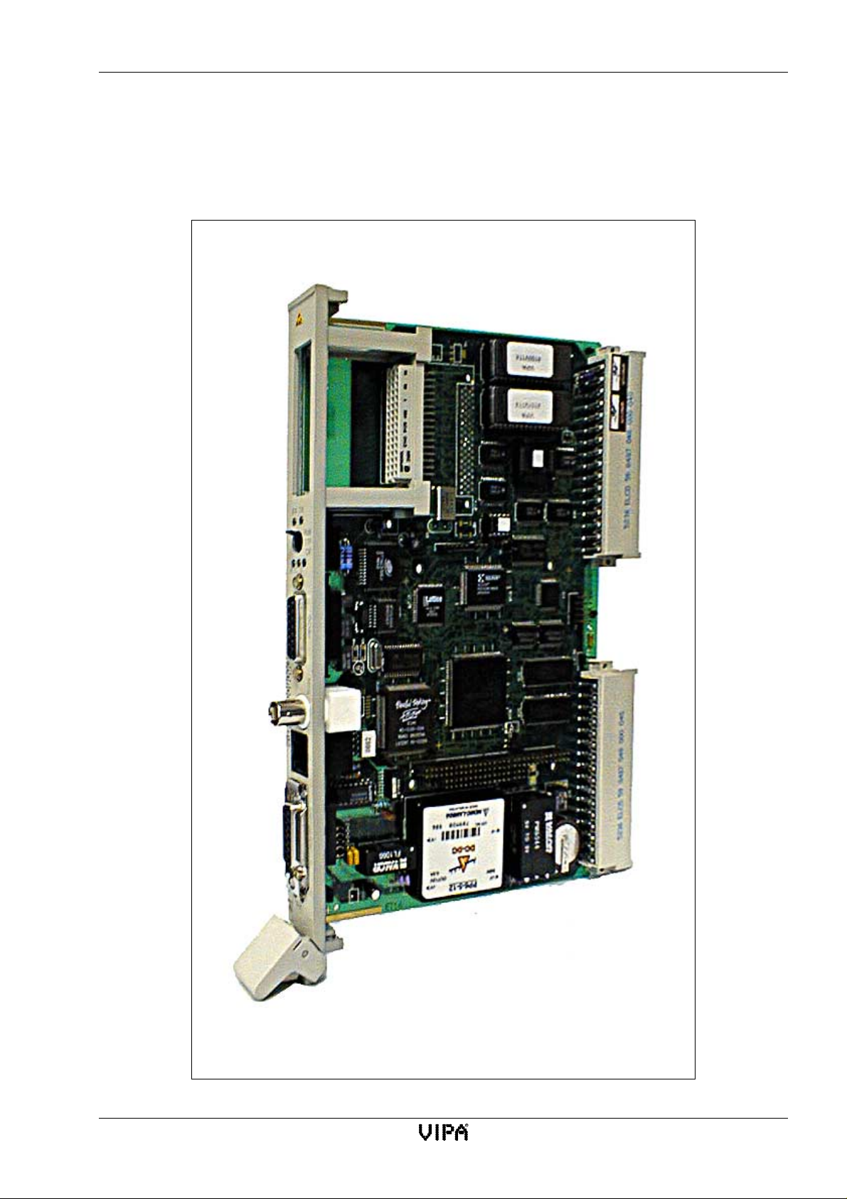
Fig. 4-1:Construction of the CP143 H1 / TCP/IP
Rev. 00/07 4-1
Page 50

The construction of the module CP143 H1 / TCP/IP manual
4.1.1 Components of the module
• 80486 SLC 33 MHz CPU
• 1MB main memory
• PG interface which is compatible with the Siemens CP1430
• EPROM socket
• 4KB dual-port RAM as CP interface
• DIN interface to the PLC
• An AUI connection (IEEE 802.3) for interfacing to a bus cable via a transceiver, RJ45
signal may be connected to the AUI socket (Siemens compatible)
• RJ45 interface connection for ethernet
• Thin ethernet connector (BNC)
• power supply for transceiver
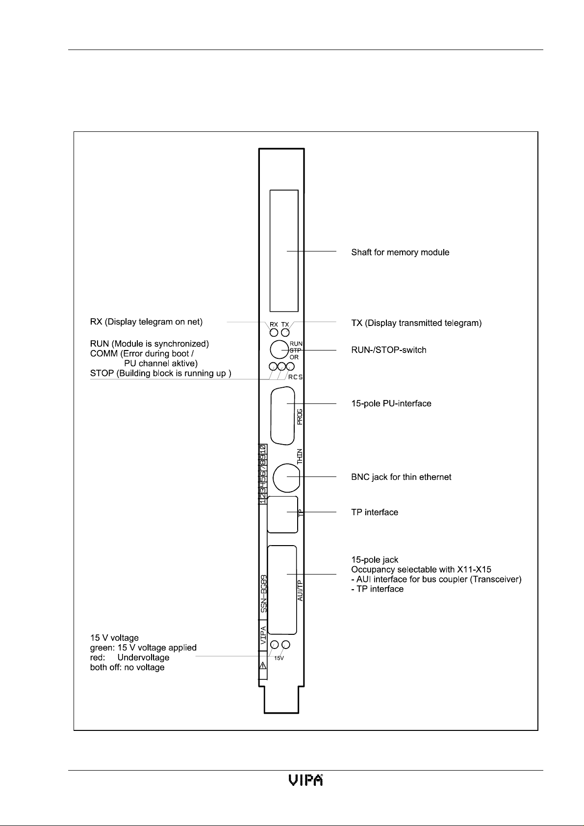
Controls and indicators located on the front panel
• LEDs for
TX (yellow) indicates that data is being transmitted.
RX (yellow) indicates any data on the network.
RUN (green) The module has been synchronized, i.e. the PLC has completed
the SYNC-procedure.
COMM (yellow) error occurred during the boot phase / FLASH-ROM is burned.
STOP (red) The module is busy initializing.
15 V (green) 15 V supply available
(red) under voltage
Both LEDs off indicates that no power is available.
• Slot for EPROMs
• 15-pole D-type plug for the PG interface
• AUI interface for a transceiver
• BNC socket for thin ethernet
• RJ45 socket for ethernet
• RUN-/STOP-/RESET switch
RESET sets the module to defauft-setting. To reset the module you have to keep pressed
the RUN-/STOP-/RESET-switch in position OG about 5 seconds.
4-2 Rev. 00/07
Page 51
CP143 H1 / TCP/IP manual The CP143 H1 / TCP/IP network board
4.1.2 Jumper settings
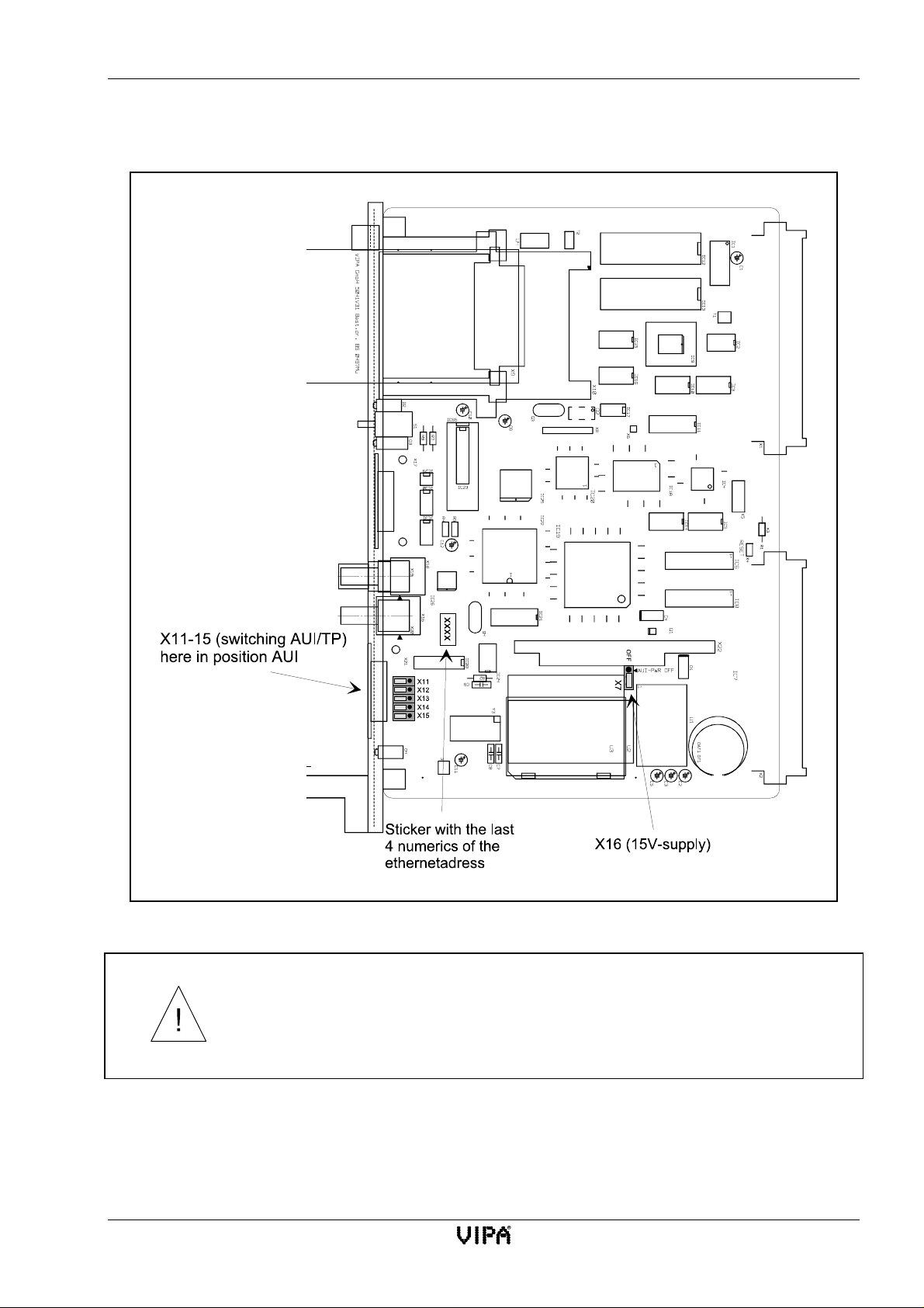
Fig. 4-2:Location of jumpers
Jumpers X11 to X15 must either all face left or face right! Any other
combination could cause permanent damages to the module!
The configuration of this module is determined by means of jumpers. You must install 5 jumpers to
change from AUI to TP mode. X7 is used to enable the 15V supply voltage for the transceiver. The
remaining jumpers on the module do not affect the configuration. However, they must not be altered
to ensure the module operates properly.
Rev. 00/07 4-3
Page 52
The construction of the module CP143 H1 / TCP/IP manual
4.1.2.1 AUI / TP (X11-X15) changeover
This jumper determines the pin-allocation of the 15-pin socket. You may choose between twisted
pair (TP) and AUI.
Jumpers X11 to X15 must always be in the same position.
1-2 linked The 15-pin socket is set for AUI. (default)
2-3 linked The 15-pin socket is set for twisted pair operation. (Siemens compatible)
Jumpers X11 to X15 must either all face left or face right! Any other
combination could cause permanent damages to the module!
4.1.2.2 Selection of +15V supply voltage (X7)
This jumper enables the +15V supply for the transceiver:
1-2 linked transceiver supply voltage off.
2-3 linked transceiver supply voltage on. (default)
The jumpers that are not described in this section must be installed for normal
operation but they may not be changed!
4-4 Rev. 00/07
Page 53
CP143 H1 / TCP/IP manual The CP143 H1 / TCP/IP network board
4.1.3 Sockets and plugs
4.1.3.1 The position of sockets and plugs
Fig. 4-3:Front view CP143 H1 / TCP/IP
Rev. 00/07 4-5
Page 54
The construction of the module CP143 H1 / TCP/IP manual
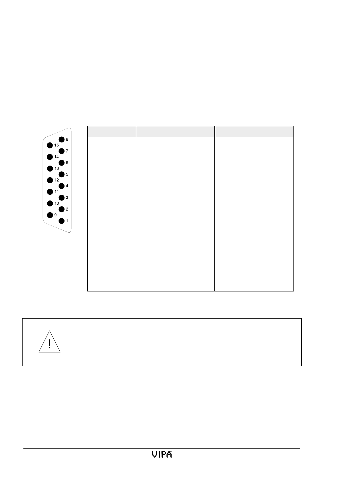
4.1.3.2 Pin-configuration for sockets and plugs
The figures show the respective sockets when the module is viewed from the frame. The top of the
figure is equivalent to the top of the frame.
4.1.3.2.1 Pin-assignment for the AUI-/TP socket (15-pole)
The 15-pole D-type socket connects to a transceiver via a drop-cable. It has a sliding interlock. The
pin-assignment for this connector for both, the AUI interface and the TP interface (twisted pair) is
depicted below.
Pin AUI TP
1 Signal ground 2 CLSN (Collision+) 3 TRMT (Transmit+) TRMT (Transmit+)
4 Signal ground 5 RCV (Receive+) RCV (Receive+)
6 12V return Link to 7
7- Linkto6
8 Signal ground -
9 CLSN (Collision-) 10 TRMT (Transmit-) TRMT (Transmit-)
11 Signal ground 12 RCV (Receive-) RCV (Receive-)
13 +12V 14 Signal ground 15 - -
Tab. 4-1: Pin configuration of the 15-pole AUI-/TP socket
Pins that are not connected may not be used as this could damage the module
or the connected peripheral!
4-6 Rev. 00/07
Page 55
CP143 H1 / TCP/IP manual The CP143 H1 / TCP/IP network board
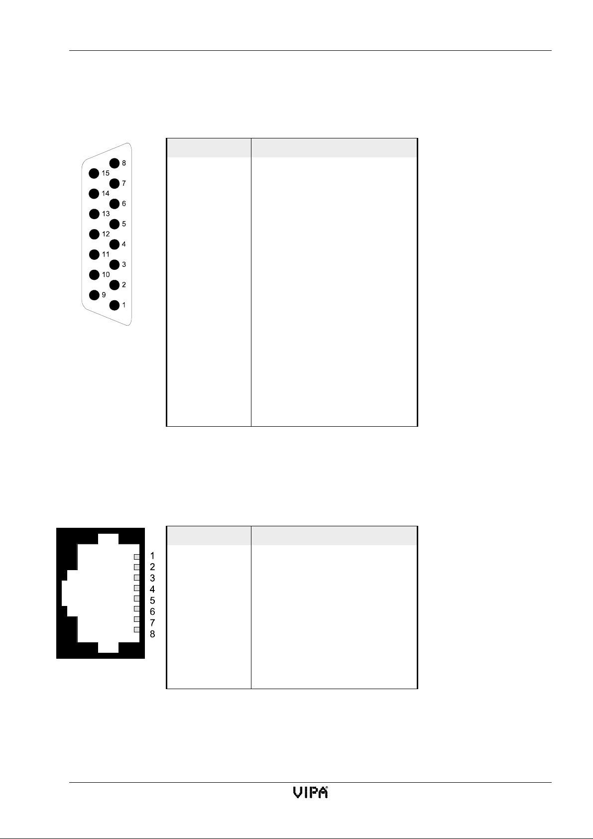
4.1.3.2.2 Pin configuration for the D-type socket with PG interface (15-pole)
The 15-pole D-type socket with the screw-type locks is intended for the connection of a
programmer. The following table shows the pin-configuration for the socket:
Pin Signal
1 MEXT (external ground, screen)
2 TT Y IN - (current output)
34 +24V
5 Ground (internal ground)
6 TTY OUT + (current input)
7 TTY OUT - (current output)
8 MEXT (external ground)
9 TTY IN + (current input)
10 24V return
11 20mA current source of the transmitter
12 Ground (internal ground)
13 20mA current source of the receiver
14 Master signal
15 Ground (internal ground)
Tab. 4-2: Pin configuration of the PG interface
4.1.3.2.3 Pin configuration of the TP socket (RJ45)
Pin Signal
1Transmit+
2Transmit-
3 Receive +
4-
5-
6 Receive -
7-
8-
Tab. 4-3: Configuration of the TP socket (RJ45)
Rev. 00/07 4-7
Page 56

The construction of the module CP143 H1 / TCP/IP manual
4.1.3.2.4 Base connector (48-pole knife-edge connector)
Base connector X1
db z
nc M +5V 2
UBAT PESP nc 4
ADB12 ADB00 /CPKL 6
ADB13 ADB01 /MEMR 8
ADB14 ADB02 /MEMW 10
ADB15 ADB03 /RDY 12
nc ADB04 DBO 14
nc ADB05 DB1 16
nc ADB06 DB2 18
nc ADB07 DB3 20
nc ADB08 DB4 22
nc ADB09 DB5 24
nc ADB10 DB6 26
DSI ADB11 DB7 28
+24V BASP M24V 30
nc M nc 32
Base connector X2
dbz
nc M +5V 2
nc nc nc 4
nc nc nc 6
nc nc nc 8
nc nc nc 10
nc nc nc 12
nc nc nc 14
nc nc nc 16
nc nc nc 18
nc nc nc 20
/TxDSN nc nc 22
nc nc nc 24
nc /RxDSN nc 26
nc nc nc 28
nc nc M24V 30
nc M +24V 32
4-8 Rev. 00/07
Page 57

CP143 H1 / TCP/IP manual The CP143 H1 / TCP/IP network board
4.1.3.2.5 EPROM socket
ab c
1 VCC GND A12
2A2A1A0
3A5A4A3
4A8A7A6
5 A11 A10 A9
6-RDA14A13
7D9D8-WR
8 D12 D11 D0
9 D15 D14 D13
10 D2 D1 D0
11 D5 D4 D3
12 K1 D7 D6
13 K2 -CS3 -CS1
14 K3 -CS4 -CS2
15 K4 PSW UBAT
16 K5 GND VPP
Rev. 00/07 4-9
Page 58

The CP143plus firmware CP143 H1 / TCP/IP manual
4.2 The CP143plus firmware
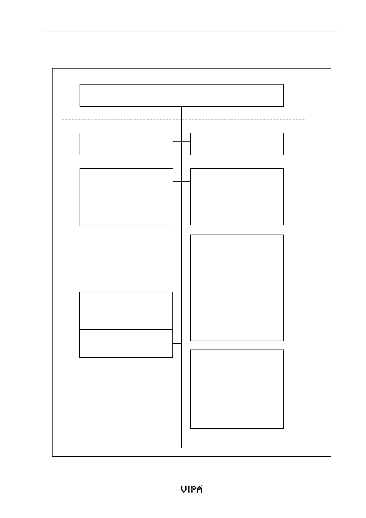
Fig. 4-4 shows the structure of the CP143plus firmware. This figure contains those components that
interact to determine the characteristics of the CP.
4.2.1 Components
The individual components communicate via the operating system functions of a real-time kernel
(RTK). In addition to this, class libraries have been defined which provide a defined CALL
interface.
4.2.1.1 Interface
The interface between the PLC and the CP is provided by a dual-port-RAM that has been divided
into four equal segments, so-called tiles. In a multi-processor PLC every CPU may communicate
independently with the CP143plus by means of one of these four tiles.
The handler modules send-request and receive-request have been implemented by the use of
interrupts (interrupt handler) and by exchanging data via the dual-port-Ram.
4.2.1.2 H1-application
The H1-application is the protocol controller for the functions defined for the CP.
4.2.1.3 H1-interface
The H1-API-calls are available as a class library and they define the interface for the protocol stack.
4-10 Rev. 00/07
Page 59
CP143 H1 / TCP/IP manual The CP143 H1 / TCP/IP network board
4.2.2 The structure of the CP143plus
Dual-port-Ram (DPR)
PLC-interrupt
Interrupt handler and task
H1- application
The application consists of n
tasks. That is, a new task is
generated and administered
for every configured connection.
TP4-API-Calls
Libraries containing access
functions for the TP4-protocol
stack
PG-interrupt
Interrupt handler and task
Tools
• List processing
• access routines
• All-HTB-coordinator
• ...
System-Boot
Synchronous supervision
• The initialization task scans
the parameter sets.
• The synchronization task
checks switch settings and
controls the indicators locatedontheCP
TP4(H1)
protocol stack
The operating system is
divided into three independent
units.
A real-time kernel defines the
interface for tasks and handlers
Fig. 4-4:The structure of the CP143plus
Rev. 00/07 4-11
Operating system
Page 60

The CP143plus firmware CP143 H1 / TCP/IP manual
4.2.3 Further information on the CP143plus
4.2.3.1 System properties
The system properties of a CP must not be regarded as limitations or as design faults. Instead,
certain functions may not be accessible or they have been removed for the security of the overall
system.
• The run-up time of the CP143plus is app. 10 seconds. For this reason the requirements of
balanced synchronization characteristics (an HTB synchronization module waits between 8 and
10 seconds, depending on the type of CPU) can not be met. Thus the start-up OBs 20-22 must
perform the following actions:
• poll the PAFE of the HTB in synchronous mode until this becomes 0. After 10 seconds
the tile will be set to active by the CP.
• If the synchronous HTB still detects a PAFE after 15 seconds then the PLC, the
configuration of the PLC or the CP is incorrect. In this case the respective configuration
must be checked.
• Depending on the sequence in which the synchronous HTBs were initiated, the CP may detect a
synchronous request and re-boot when more than one tile of a CP must be synchronized. Under
these conditions the CP would never be synchronized. Cure: switch the CP to STOP by means of
the respective switch, then synchronize all the required tiles. Change the switch back to RUN. At
this point the CP has been synchronized. This reaction of the system can only occur during
commissioning, and then only, if the number of tiles of the CP is increased and the new
synchronous HTB is not accessed as the last one in the sequence.
• Tasks having a priority of 0/1 can only send and/or receive the amount of data as defined by the
synchronous HTB. Tasks of this type are not blocked. This results in a maximum data transfer
rate of 512 bytes per task and a block size of 255 (see also block size).
• RECEIVE tasks, that are mirrored as broadcast communication, can not receive all data messages
from a fast cyclic transmitter. Messages that have not been received are discarded to protect the
system.
4-12 Rev. 00/07
Page 61

CP143 H1 / TCP/IP manual The CP143 H1 / TCP/IP network board
4.2.3.2 Generation of a multicast address from the ethernet address
The TP4 protocol stack generates a MC address from the ethernet address. This function is required
as the ethernet controller (hardware) uses the MC address for message filters.
4.2.3.3 Broadcast
The broadcast address is always FFFFFFFFFFFFh.
4.2.3.4 block size
Every configured interface of the CP must be synchronized by the handler module SYNCHRON
when a PLC is started. This applies to every type of start-up of the respective PLC:
• OB20 for a new start
• OB21 for a manual re-start
• OB22 for a re-start after a mains power failure
block size CP block size in bytes
1
0 Default block size for a CPU. This may differ,
depending on the type of CPU.
116
232
364
4 128
5 256
6 512 (for the READ/WRITE function)
255 512
Tab. 4-4: block size
1)
The first transfered block for the READ/WRITE function is 16 Bytes (length of READ/WRITE
Header) shorter as the set block length.
Rev. 00/07 4-13
Page 62

CP143 TCP/IP firmware CP143 H1 / TCP/IP manual
4.3 CP143 TCP/IP firmware
Fig. 4-5 shows the structure of the CP143 TCP/IP firmware. This figure contains those components
that interact to provide the functionality of the CP.
4.3.1 Components
The individual components communicate via the operating system functions of a real-time kernel
(RTK). In addition to this, class libraries have been defined which provide a defined CALL
interface.
4.3.1.1 Interface
The interface between the PLC and the CP is provided by a dual-port-RAM that has been divided
into four equal segments, so-called tiles. In a multi-processor PLC every CPU may communicate
independently with the CP143 TCP/IP by means of one of these four tiles.
The handler modules send-request and receive-request have been implemented by the use of
interrupts (interrupt handler) and by exchanging data via the dual-port-Ram.
4.3.1.2 TCP/IP application
The TCP/IP-application is the protocol controller for the functions defined for the CP.
4.3.1.3 TCP/IP-Interface
The TCP/IP-API-calls are available as a class library and they define the interface for the protocol
stack.
4-14 Rev. 00/07
Page 63
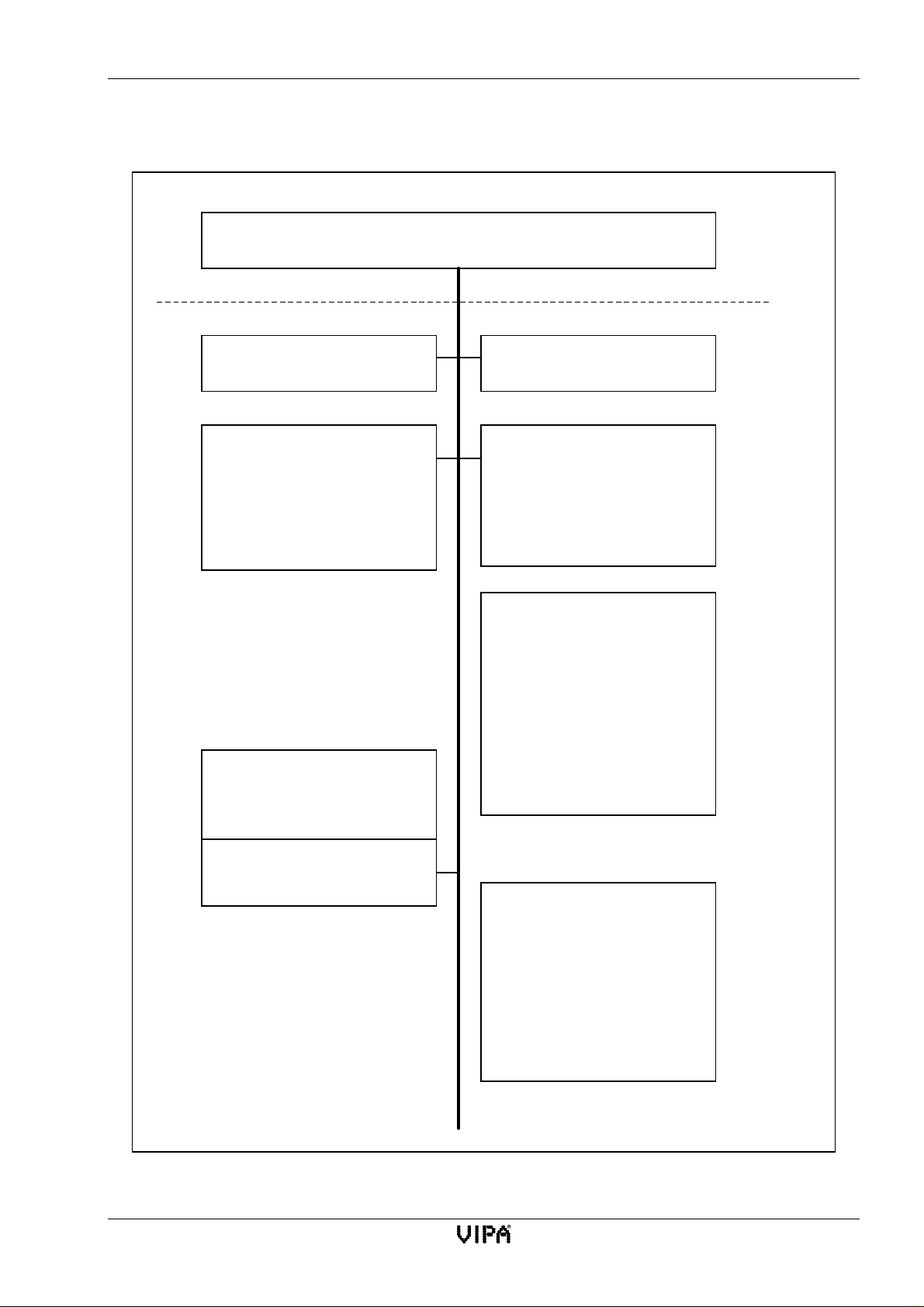
CP143 H1 / TCP/IP manual The CP143 H1 / TCP/IP network board
4.3.2 The structure of the CP143 TCP/IP
Dual-port-RAM (DPR)
PLC-Interrupt
Interrupt handler and task
TCP-IP Application
The application consists of n
tasks. That is, a new task is
generated and administered
for every configured connection.
TP4-API-Calls
Libraries containing access
functions for the TP4-protocol
PG-Interrupt
Interrupt handler and task
Tools
• List processing
• access routines
• All-HTB-coordinator
• ...
System-Boot
Synchronous supervision
• The initialization task scans
the parameter sets.
• The synchronization task
checks switch settings and
controls the indicators
located on the CP
TCP/IP
protocol stack
The operating system is
divided into three independent
units.
A real-time kernel defines the
interface for tasks and handlers
Fig. 4-5:The structure of the CP143 TCP/IP
Rev. 00/07 4-15
Operating system
Page 64

CP143 TCP/IP firmware CP143 H1 / TCP/IP manual
4.3.3 Further information on the CP143 TCP/IP
4.3.3.1 System properties
The system properties of a CP must not be regarded as limitations or as design faults. Instead,
certain functions may not be accessible or they are purposely removed for the security of the overall
system.
• The run-up time of the CP143 TCP/IP is app. 10 seconds. For this reason the requirements of
balanced syncronization characteristics (an HTB synchronization module waits between 8 and 10
seconds, depending on the type of CPU) can not be met. Thus the start-up OBs 20-22 must
perform the following actions:
− poll the PAFE of the HTB in synchronous mode until this becomes 0. After 10 seconds
the tile will be set to active by the CP.
− If the synchronous HTB still detects a PAFE after 15 seconds then the PLC, the
configuration of the PLC or the CP is incorrect. In this case the respective configuration
must be checked.
• Depending on the sequence in which the synchronous HTBs were initiated, the CP may detect a
synchronous request and re-boot when more than one tile of a CP must be synchronized. Under
these conditions the CP would never be synchronized. Cure: use the respective switch to STOP
the CP, then synchronize all the required tiles. Change the switch back to RUN. At this point the
CP has been synchronized. This is reaction of the system can only occur during commissioning,
and then only, if the number of tiles of the CP is increased and the new synchronous HTB is not
accessed as the last one in the sequence.
• The joker size (-1, 0xFFFF) is not permitted for the length of the ORG-format, the application (in
this case the PLC user) must specify the length of the receive data exactly.
• Tasks having a priority of 1 can only send and/or receive the amount of data as defined by the
synchronous HTB. Tasks of this type are not blocked. This results in a maximum data transfer
rate of 512 bytes per task and a block size of 255 (see also block size).
• RECEIVE tasks, that are mirrored as broadcast communication, can not receive all data messages
from a fast cyclic transmitter. Messages that have not been received are discarded to protect the
system.
• The TCP/IP protocol stack has a global pool of buffers that contain the receive and transmit
buffers. It is possible that system collisions occur in this area if:
− the data for a receive task was not retrieved. After a certain period of time a lack of
resources occurs, and other connections will issue disconnects once the respective
predefined time-out has occurred. Proper communications will only be possible once the
receive buffers of the original connection have been released (termination) or when the
available data was retrieved by means of the RECEIVE HTBs.
− one or more cyclic transmitters place a heavy load on the CP. The CP will also terminate
connections when a lack of resources occurs.
− a transmitter has sent two or more messages and the receiver did not have the opportunity to
retrieve them. In this case the unknown type of data would cause a collision in the receiver.
The CP does not permit that this situation occurs. The PLC application demands a definite
receive size which excludes the joker-size. The receive size of prio 0/1-RECEIVE tasks is
set implicitly by the defined block size (16, 32, 64, 128, 256, 512 bytes).
4-16 Rev. 00/07
Page 65
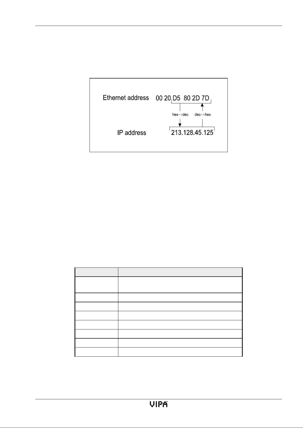
CP143 H1 / TCP/IP manual The CP143 H1 / TCP/IP network board
4.3.3.2 The relationship between the ethernet ADR for H1 and the IP-ADR for TCP/IP
The CP 143 TCP/IP has a default ethernet address after it was turned on for the first time or after it
has been reset. This address is supplied as “Node Address” on the “test report” that accompanies the
module.
You can determine the IP address from the ethernet address by means of the following calculation:
Fig. 4-6:Conversion of ethernet address into an IP address
The remote IP address is the address of the destination module. This is a 32-bit address that must be
unique within the network. The address consists of 4 numbers that are separated from each other by
a full stop.
4.3.3.3 Broadcast
The broadcast address is always 255.255.255.255.
4.3.3.4 block size
Every configured interface of the CP must be synchronized by the handler module SYNCHRON
when a PLC is started. This applies to every type of start-up of the respective PLC:
• OB20 for a new start
• OB21 for a manual re-start
• OB22 for a re-start after a mains power failure
block size CP block size in bytes
1
0 Default block size for a CPU. This may differ,
depending on the type of CPU.
116
232
364
4 128
5 256
6 512
255 512
Tab. 4-5: block size
1)
The first transfered block for the READ/WRITE function is 16 Bytes (length of READ/WRITE
Header) shorter as the set block length.
Rev. 00/07 4-17
Page 66

CP143 TCP/IP firmware CP143 H1 / TCP/IP manual
4.3.4 Organization format (ORG format)
The organization format is another name for an addressing structure that describes the data areas of
the PLC. For READ and WRITE the ORG block is optional.
The ORG identifier defines the memory area that must be addressed.
The ERW identifier is important when data modules must be addressed. In this case the respective
data module number must be entered into this location. The start address and the size address the
memory area and they are entered in HIGH-/LOW format (Motorola formatted addressing)
Description Type Area
ORG identifier BYTE 1..x
ERW identifier BYTE 1..255
Start address HILOWORD 0..y
Size HILOWORD 1..z
Tab. 4-6: Organization format
PLC area DB MB EB AB
ORG identifier 01h 02h 03h 04h
Description source/destination data
from/into data module in
main memory
DBNR
valid range:
Start address
Significance
valid range:
Quantity
Significance
valid range:
DB, from where source
data is read or to which
destination data is
written.
1...255
DW-No., from where
data is read or where
data will be written.
1...2047
Length of the source/
destination data block in
words
1...2048
source/destination data
from/into clipboard
irrelevant irrelevant irrelevant
MB-No., from where
data is read or where
data will be written.
*)
0...255
Length of the source/
destination data block
in bytes
1...256
source/destination data
from/into process
image of the inputs
(PAE)
EB-No., from where
data is read or where
data will be written.
0...127
Length of the source/
destination data block
in bytes
1...128
source/destination data
from/into process
image of the outputs
(PAA)
AB-No., from where
data is read or where
data will be written.
0...127
Length of the source/
destination data block
in bytes
1...128
Tab. 4-7: ORG-formats for PLCs (ORG identifier 01h-04h)
*)
only up to MB199 for the AG150
4-18 Rev. 00/07
Page 67

CP143 H1 / TCP/IP manual The CP143 H1 / TCP/IP network board
PLC area PB ZB TB BS
ORG-identifier 05h 06h 07h 08h
Description Source/destination data
from/into peripheral
module. Input modules
for source data, output
modules for destination
data
DBNR irrelevant irrelevant irrelevant irrelevant
Source/destination data
from/into counter cells
Source/destination data
from/into timer cells
Source/destination data
from/into system data
area (BS and BS')
Start address
Significance
valid range:
Quantity
Significance
valid range:
PLC area AS DX QB SM
ORG-identifier 09h 0Ah 11h 10h
Description Source/destination data
DBNR
PB-No., from where the
data is read or where
data is written.
0...127 digital periph.
128...255 anal. periph.
Length of source/
destination data block in
bytes
1...256
Tab. 4-8: ORG-formats for PLCs (ORG-identifier 05h-08h)
from/into absolute
addressed memory cells
irrelevant DX, from where source
ZB-No., from where
the data is read or
where data is written.
0...255
Length of source/
destination data block
in words
(counter cell = 1 word)
1...256
Source/destination data
from/into extended
data module (for
AG135U)
data is read or where
destination data is
written.
TB-No., from where
the data is read or
where data is written.
0...255
Length of source/
destination data block
in words
(counter cell = 1 word)
1...256
Source/destination
from/in periph.-module
in the ext. peripheral
area.
Input module for
source data, output
module for destination
data (AG150U only)
irrelevant irrelevant
Number of the BSword from where the
data is read or to
where the data is
written.
0...511
Length of source/
destination data block
in words
1...128
Source/destination data
from/in special flag
area
valid range:
Start address
Significance
valid range:
Quantity
Significance
valid range:
absolute start address,
from where the data is
read or where data is
written.
0h...FFFFh
Length of source/
destination data block in
words
1...32767
Tab. 4-9: ORG-formats for PLCs (ORG-identifier 09h-11h)
1...255
DW-No. from where
the data is read or
where data is written.
0...2047
Length of source/
destination data block
in words
1...2048
PB-No. from where the
data is read or where
data is written.
0...511
Length of source/
destination data block
in Bytes
1...256
Special flag-Nr. from
where the data is read
or where data is written
Lenght of source/
destination data block
in Bytes
1...1024
Rev. 00/07 4-19
Page 68

CP143 TCP/IP firmware CP143 H1 / TCP/IP manual
4.3.5 Structure of the PLC-header
The following messages lists the valid ORG identifiers. The entered "length" must never be -1
(FFFFh).
4.3.5.1 FETCH/WRITE
for WRITE
Request message
Acknowledgement message
System identifier ="S"
Header length =16d
Ident. OP-code =01
OP-code length =03
OP-code =03
ORG-block =03
ORG-block length =08
ORG-identifier
DBNR
Start- H
address L
Length H
Unused block =FFh
Length unused bl. =02
Up to 64K data but only for error
for READ
No.=0
Request message
="5"
L
System identifier ="S"
="5"
Header length =16d
Ident. OP-code =01
OP-code length =03
OP-code =04
Acknowl. block =0Fh
ACK-block length =03
Error No. =No.
Unused block =FFh
Length unused block =07
not used
Acknowledgement message
System identifier ="S"
="5"
Header length =16d
Ident. OP-code =01
OP-code length =03
OP-code =05
ORG-block =03
ORG-block length =08
ORG-identifier
DBNR
Start- H
address L
Length H
L
Unused block =FFh
Length unused bl. =02
System identifier ="S"
="5"
Header length =16d
Ident. OP-code =01
OP-code length =03
OP-code =06
Acknowl. block =0Fh
ACK-block length =03
Error No. =No.
Unused block =FFh
Length unused block =07
not used
Up to 64K data but only for error
No.=0
4-20 Rev. 00/07
Page 69

CP143 H1 / TCP/IP manual The CP143 H1 / TCP/IP network board
4.3.5.2 SEND / RECEIVE with TRADA (Transparent data exchange)
TRADA stands for transparent data exchange. Transparent data exchange allows to transmit data of
varied length. A 16-byte header which indicates the length is preceding the user data which have to
be transmitted.
For the use of TRADA it is permitted to give in the PLC user program a joker length within the
length instruction.
Through the input of –1 as a lengths instruction into the RECEIVE-FB (parameter: ZLAE) a
variable user data length (joker length) can be adjusted. For the use of a joker length the respective
data length will be taken on.
The as following described header precedes with TRADA functionality a SEND command and is
evaluated from the RECEIVE command.
SEND with the type TRADA
OP-code = 07
System identifier ="S"
="5"
Header length =16d
Ident.OP-code =01
OP-code lenght =03
OP-code =07
ORG-block =03
ORG-block length =08
ORG-identifier
DBNR (nicht relevant)
Start- H
adress L
Length H
L
Unused block =FFh
Length unused block =02
Up to 64K data but only for error
No.=0
→ length instruction of used data
length instruction
With the length instruction the number of the bytes of a data block is named.
If you synchronise with a block size of 6 (512 Byte), the length instruction results in words
Rev. 00/07 4-21
Page 70
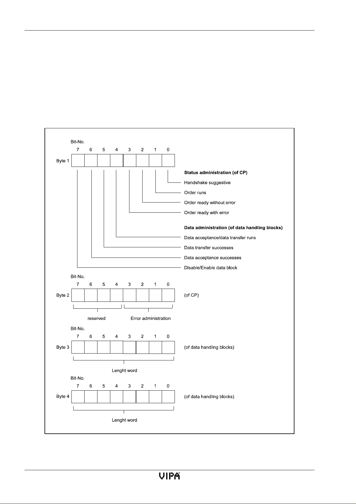
CP143 TCP/IP firmware CP143 H1 / TCP/IP manual
4.3.6 Status- and error indicators
Status and error indicators are provided by the handler modules
• via the ANZW indicator word (information for task processing)
• via the configuration error byte PAFE (indicator for an incorrect configuration for a task)
4.3.6.1 Contents and structure of the indicator word ANZW
The indicator word has the following structure:
Fig. 4-7:The structure of the indicator word ANZW
4-22 Rev. 00/07
Page 71

CP143 H1 / TCP/IP manual The CP143 H1 / TCP/IP network board
• Status management byte 1, bit 0 to bit 3
These indicate whether a task has already been started, whether an error has occurred or whether
the task has been inhibited, e.g. if a virtual connection does not exist.
Bit 0: Handshake possible
Set: by the interface according to the "Reset"-indicator in the task status bit.
Handshake possible (=1) is used by the RECEIVE-module. (Message
available for PRIO 1 - or - RECEIVE-initiation possible for PRIO 2/3)
Check: by means of the RECEIVE-module: RECEIVE will only initiate a handshake
with the CP when this bit is set. By the application: for RECEIVE-request
(check, whether a message is available for PRIO 1).
Bit1:Taskactive
Set: by the interface, when the task was sent to the CP.
Reset: by the interface once a task has been completed (e.g. acknowledgement
received).
Check: by means of handler modules: a new task will only be issued when the “old”
task has been completed.
by the user: to check whether it is sensible to trigger a new task.
Bit 2: Task completed without errors
Set: by the interface, once the respective task has been completed without errors.
Reset: by the interface when the task is started again.
Check: by the user, to check whether the task was completed without errors.
Bit 3: Task completed with errors
Set: by the interface, if the respective task was completed with errors. The reason
for the error is available from the high part of the indicator word.
Reset: by the interface, when the task is started again.
Check: by the user: to check whether the task was completed with errors. If the bit for
“task completed with error” is set, then the high byte of the indicator word
contains the reason for the error.
Rev. 00/07 4-23
Page 72

CP143 TCP/IP firmware CP143 H1 / TCP/IP manual
• Data management byte 1, bit 4 to bit 7
This area indicates whether a data transfer is still active or whether data transmission or reception
has been completed. The "Enable / Disable" bit can be used to inhibit the transfer of data for the
respectivetask.(Disable=1;Enable=0).
Bit 4: Data transmission / reception is active
Set: by handler modules SEND, RECEIVE, once the transmission/reception of
data for a task has been started. The transfer may be executed by means of the
ALL function (instead of a DMA) that was initiated by SEND-DIREKT.
Reset: by handler modules SEND, RECEIVE, after the data transfer has been
completed (last partial block has been transferred).
Check: by the user: the user must not change the data of a task while the
CP<< >>PLC transfer is active. This is not critical for PRIO 0/1 tasks as the
transfer can be completed by a single run of the respective module. Larger
quantities of data, however, can only be transferred in multiple blocks. This
blocking requires a number of PLC-cycles. To ensure the consistency of the
data the user must check whether the respective block is currently being
transferred before proceeding with changes.
BIT 5: Data transmission completed
Set: by handler module SEND, after the transmission of data for the respective
task has completed.
Reset: by handler module SEND, once the data transmission for a new task (new
trigger) has started.
by the user: when the status was checked (edge triggered).
Check: by the user: this bit may be used to determine whether a data set for a task has
been transferred to the CP, or whether a new data set may be supplied to the
active task (e.g. cyclic data transfer)
Bit 6: Data reception completed
Set: by handler module RECEIVE, after the reception of data for the respective
task has completed.
Reset: by handler module RECEIVE, once the data transfer from a new task (new
trigger) to the PLC has started. By the user, when the status was checked
(edge triggered).
Check: by the user: this bit indicates whether the transfer of the current data set for
the respective task has been completed or whether the transfer of a new data
set to the PLC has been completed.
4-24 Rev. 00/07
Page 73

CP143 H1 / TCP/IP manual The CP143 H1 / TCP/IP network board
Bit 7: Disable / enable blocking of data
Set: by the user: to prevent overwriting of a block of data by the RECEIVE-
module or to stop transmission of a data block by the SEND-module (only for
the first data block).
Reset: by the user: to release the respective data block.
Check: by means of handler modules SEND and RECEIVE. When bit 7 is set these
modules will not transfer any data and indicate to the CP that an error has
occurred.
•
• Error management byte 2, bit 0 to bit 3
• •
This location contains the error flags returned by a task. The error flags are only valid when the
bit “Task completed with errors” in the status bit is set as well.
The following error messages are possible:
0 no error
If the “Task completed with errors” bit is set, then the CP143 H1 / TCP/IP has reestablished the connection, e.g. after a restart or a RESET.
1 incorrect Q/ZTYP at the HTB
The TYP-identifier for the task was incorrect.
2 The specified area does not exist in the PLC
The configuration of the DB (DBNR) for a task was incorrect.
3 The area in the PLC is too small
The sum of Q/ZANF and Q/ZLAE exceeds the limits of the area. The area-limits of data
modules is determined by the size of the module. The limits for flags, timers, counters, etc.
depend on the PLC.
4 QVZ-error in the PLC
The source or destination parameters refer to an area in the PLC that contains defective
memory or no memory at all. The error QVZ can only occur for Q/ZTYP AS, PB, QB or
when memory has been damaged.
5 Error in the indicator word.
The configured indicator word can not be processed. This error may occur when ANZW
refers to a data word or double word that never did or is no longer located in the specified
data module. That is, the DB is too small or does not exist.
6 no valid ORG format
The destination or the source for the data was not specified, neither in the handler module
(Q/TYP="NN") nor in the connection module.
7 Reserved
8 no unused transport connections
The capacity for transport connections has been exceeded. Please delete unnecessary
connections.
Rev. 00/07 4-25
Page 74

CP143 TCP/IP firmware CP143 H1 / TCP/IP manual
9 Remote error
An error occurred at the remote station during a READ/WRITE task.
A Connection error
The connection for a task has not been established. This error will disappear as soon as a
connection can be established. When all connections of a CP are in the interrupted state the
module or the LAN cable may have been damaged. This error may also occur due to a
configuration error, e.g. incorrect addressing.
B Handshake error
This error may be a system error or the size of the data block is too large.
C Initiation error
A task was initiated by means of the wrong handler module or the transferred data block
was too large.
D Termination after RESET
This is an operational indicator. The connection is terminated for priority 1 and 2 and it
will only be re-established once the remote station is ready for a new connection. Priority 3
connections are terminated. These may be initiated again.
E Task with boot-function
This is an operational indicator. This is a READ/WRITE-PASSIV task and can therefore
not be started by the PLC.
F Task does not exist
The task that was addressed has not been configured on the CP143 H1 / TCP/IP. This error
may occur if the SSNR/A-NR combination has been entered incorrectly into the handler
module or when a connection module has not been entered.
Bits 4 to 7 of byte 2 are reserved and intended for future expansion.
•
• Length-word byte 3 and byte 4
• •
The length word is used by the handler modules (SEND, RECEIVE) to deposit the amount of
data for the respective task that has already been transferred. This means the amount of data
already received for receive tasks and the amount of data transmitted for send tasks.
Write: this word is changed by SEND and RECEIVE while the data transfer is active.
The "length-word" is calculated from:
current amount transferred + quantity of data already transferred
Reset: overwrite or by each new SEND, RECEIVE, FETCH task.
The “length-word” contains the current source or destination quantity when the bit
"Task completed without error" or "Data transmission/reception completed" is set.
When the bit “Task completed with errors” is set, then the length word contains
the amount of data that was transferred before an error occurred.
4-26 Rev. 00/07
Page 75

CP143 H1 / TCP/IP manual The CP143 H1 / TCP/IP network board
4.3.6.2 Important status and error indicators of the CP143 H1 / TCP/IP
Here follow important status and error indicators that may be signalled via the “indicator word”.
The data consists of "HEX"-patterns that are similar to those of the status / control-var-test function
of the PG on the PLC. The X indicates “arbitrary” or “irrelevant"; No. is the error number.
Indicator words that may occur are
Indicatorword:XFXA
Error indicator "F" signifies that the respective task has not been defined on the CP 143. The task is
blocked by the status indicator A (for SEND / FETCH and RECEIVE).
Indicatorword:XAXA
Error indicator "A" signifies that the connection for the communication task has not been
established. Status indicator "A" inhibits SEND as well as RECEIVE and FETCH.
Indicator word: X 0 X 8
The connection has been established again (e.g. when the CP has restarted) and SEND is enabled
(SEND-communication task).
Indicator word: X 0 X 9
The connection has been established again, RECEIVE is enabled. (RECEIVE-communication task).
Indicator word: X 0 2 4
SEND was processed without errors, the data has been transferred.
Indicator word: X 0 4 5
RECEIVE was processed without errors, the data was received by the PLC.
Indicator word: X 0 X 2
The SEND, RECEIVE, READ or the WRITE task is active. For a SEND task the indicator signifies
that the remote has not yet changed to RECEIVE. For a RECEIVE task the indicator signifies that
the remote has not issued a SEND.
Rev. 00/07 4-27
Page 76

CP143 TCP/IP firmware CP143 H1 / TCP/IP manual
The following tables show the most important indicator word combinations:
Indicators for SEND
H1 condition Prio 0/1 Prio 2 Prio 3/4
TCP/IP condition Prio 1 Prio 2 Prio 3
afterarestart 0A0A 0A0A 0008
after connection has been
established
afteratrigger X0X2 X0X2 X0X2
completedwithouterrors X024 X024 X024
completed with errors X No X 8 X No X 8 X No X 8
afterRESET XDXA XDXA XDX8
Tab. 4-10:Indicator word conditions for SEND
X 0 X 8 X 0 X 8 .....
Indicators for RECEIVE
H1 condition Prio 0/1 Prio 2 Prio 3/4
TCP/IP condition Prio 1 Prio 2 Prio 3
afterarestart 0A0A 0A0A 0001
after connection has been
established
afteratrigger X0X2 X0X2 X0X2
Message available X 0 X 1 ..... .....
completedwithouterrors X041 X045 X045
completed with errors X No X8 X No X 9 X No X 9
afterRESET XDXA XDXA XDX9
Tab. 4-11:Indicator word conditions for RECEIVE
Indicators for READ/WRITE-AKTIV
H1 condition Prio 0/1 Prio 2 Prio 3/4
TCP/IP condition Prio 1 Prio 2 Prio 3
after a restart 0 A 0 A
after connection has been
established
after a trigger X 0 X 2
READ completed X 0 4 4
WRITE completed X 0 2 4
completed with errors X No X 8
afterRESET XDXA
X 0 X 4 X 0 0 9 .....
X008
Tab. 4-12:Indicator word conditions for READ/WRITE-AKTIV
4-28 Rev. 00/07
Page 77
CP143 H1 / TCP/IP manual The CP143 H1 / TCP/IP network board
Here follow the indicators for SEND or RECEIVE when the handler module identifier is "NN"
(no source / destination parameters)
H1 condition Prio 0/1 Prio 2 Prio 3/4
TCP/IP condition Prio 1 Prio 2 Prio 3
completedwithouterrors X004 X004 X004
Tab. 4-13:Indicator word for SEND with an HT B-identifier "NN"
H1 condition Prio 0/1 Prio 2 Prio 3/4
TCP/IP condition Prio 1 Prio 2 Prio 3
completedwithouterrors X004 X005 X005
Tab. 4-14:Indicator word for RECEIVE with an HT B-identifier "NN"
Rev. 00/07 4-29
Page 78
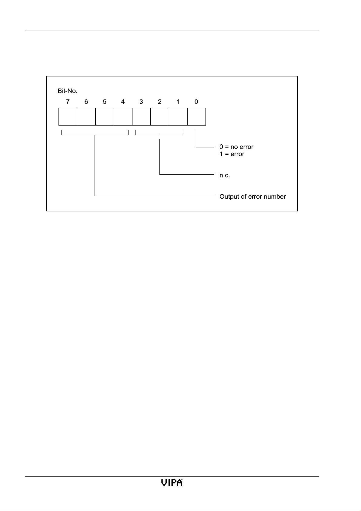
CP143 TCP/IP firmware CP143 H1 / TCP/IP manual
4.3.6.3 Parameter configuration error byte PAFE
The PAFE is set when the handler module detects a parameter error.
Error number:
0 no error
1 incorrect ORG-format
2 area does not exist
3 area too small
4 QVZ-error
5 incorrect indicator word
6 no source / destination parameter for SEND / RECEIVE ALL
7 interface does not exist
8 interface error
9 interface overload
A unused
B illegal task number ANR
C interface has not received an acknowledgement or it has not been released.
D not allocated
Fig. 4-8:Parameter error byte PAFE
E not allocated
F not allocated
4-30 Rev. 00/07
Page 79

5 Software
5.1 General 5-1
5.2 Installing and starting the program 5-2
5.3 Overview of available functions 5-3
5.4 Using on-line help 5-5
5.5 The base file 5-6
5.5.1 Loading, saving and deleting the base f ile 5-6
5.5.2 Printing the base file 5-7
5.5.3 Transferring the base file 5-8
5.6 Initialization 5-13
5.6.1 CP init 5-13
5.6.2 Online 5-15
5.6.3 System configuration 5-16
5.7 Real-time clock functions 5-17
5.7.1 General 5-17
5.7.2 Graphic representation of the real-time clock functions 5-17
5.7.3 Construction of a synchronized system: 5-18
5.7.4 Mechanism for assigning the master clock 5-18
5.7.5 Master clock initialization 5-19
5.7.6 Important considerations when using real-time clock functions 5-21
5.7.7 Setting and interrogating the clock from the PLC 5-21
5.7.8 Test functions for the clock 5-23
5.8 Configuration of connections 5-25
5.8.1 Structure of the configuration windows 5-25
5.8.2 The control field of the configuration window 5-26
5.8.3 Indirect addressing 5-27
5.8.4 Multi-connections 5-29
5.8.5 List of connections 5-31
5.8.6 Clearing all connections 5-32
5.9 General test functions 5-33
5.9.1 Ident 5-33
5.9.2 Anzw Dump 5-34
5.9.3 Overall status functions 5-36
5.10 Application in combination with H1 5-42
5.10.1 Initialization 5-42
5.10.2 Configuration of H1 connections 5-46
5.10.3 Test functions 5-52
5.11 Application in combination with TCP/IP 5-53
5.11.1 Initialization 5-53
5.11.2 Configuration of TCP/IP-connections 5-56
5.11.3 Test functions 5-65
5.11.4 OnNet-Kernel for TCP/IP of ftp 5-66
5.11.5 Microsoft kernel for TCP/IP under WINDOWS 95/NT 5-69
5.11.6 Test program for TCP/IP-Connections 5-70
5.11.7 Accessing the PLC from the PC 5-77
Page 80

Lerrzeichen
Page 81

CP143 H1 / TCP/IP manual Software
5 Software
5.1 General
This chapter consists of two parts. The first part contains a general description of the configuration
software. The second part describes the application of the configuration software to the different
protocols.
Different styles are used for the description to clarify certain aspects of the software elements. Here
follows a listing of these elements:
Style Example Description
< > <ESC> A key on your keyboard that you should press. A + indicates that
more than one key must be pressed simultaneously, e.g.
<Alt>+<F1>.
[] [Help] Button in an interactive window.
bold File An item on the main menu
italics Save Items on sub-menus
This software package contains the NCS configuration program NCS. The letters NCS are used for
Network-Communication-System. The configuration program is an MS-DOS program. Its user
interface is mouse driven and uses drop-down and pop-up windows. The program can also run in
the DOS-shell of the respective operating system, i.e. Windows 3.1x and Windows 95 as well as the
DOS-emulation of Windows NT.
This program can be used to configure H1 or TCP/IP system data, that is transport connections,
datagrams, TCP-, UDP-connections and interfaces to the PLC. The configuration applies to SEND,
RECEIVE, FETCH and WRITE jobs in the active and in the passive state.
You may use the following configuration options:
• Off-line
You configure the connection and transfer the base file into an EPROM. You may use the
VIPA EPROM programmer (Order-No.: VIPA MC5-KS85) or a PG7xx to program the
EPROM.
• On-line
-Serial
-SerialH1
- TCP/IP direct
The connection is identified by the job number. The job number is the link between the PLC and the
H1 or the TCP/IP side. The CP module can handle a maximum of 24 connections (applications).
You determine the type of connection by means of the job.
Rev. 00/07 5-1
Page 82

Installing and starting the program CP143 H1 / TCP/IP manual
5.2 Installing and starting the program
The following files are located on the disk supplied with the package:
NCS.EXE This is the executable configuration program.
NCS.TXT Except for the help text, this file contains all the documentation of
the configuration program.
NCS.HLP This is the help system.
NCS.BIB A library containing programming algorithms for EPROMs.
RUNNCS.BAT Sample Siemens EPROM driver installation.
TCPEVAL.EXE Test program for TCP/IP connections.
(only for Windows 95 and Windows NT)
You may install this software under MS-DOS or under one of the graphic user interfaces.
The following sequence is required for an MS-DOS installation:
• Change to your hard disk
C:\
• Create a directory for the programs on your hard disk.
md NCS
• Copy all files from the diskette into this directory:
COPY A:\*.* c:\NCS
• Add the following statement to your path if you require access to the NCS-software from
different subdirectories.
PATH=...C:\NCS
• Install the TCP/IP drivers if you are using a CP1413 TCP/IP adapter.
To execute the software on a PG7xx you must also install the EPROM driver and the EPROM
programmer. Chapter 5.5.3.2 describes the installation of the driver.
You can now run the program under MS-DOS.
At this stage it is possible to install the program for another user interface or another operating
system. Please refer to the respective user manual for instructions on how to install an executable
program.
To start the program under MS-DOS you can simply type NCS. The English version is started by
entering NCS -e.
Other user interfaces or operating systems usually require a double-click on the icon to start the
program. The parameters for starting the program (-e) should be entered into the field "Command
line" which is located under "Properties". Once the program has started it displays a start window
containing the version number of the software and other data.
Press a key on the keyboard and you will be presented with the main menu.
5-2 Rev. 00/07
Page 83

CP143 H1 / TCP/IP manual Software
5.3 Overview of available functions
Overview of available functionsThe overview contains a summary of the available menu functions.
This chapter also contains references to those chapters containing a description of the respective
functions.
File
Init
File
New/Load
Save
Delete
Print
Quit
Init
CP-Init
Clock-Init
Online
H1 Transport Parameter
IP TransportParameter
Systemconfiguration
Connections
H1 Transport Connection
H1 Datagram Connection
TCP connection
UDP connection
Clear all Connections
Transfer
Database< > MC5-EPROM
Database< > PG-EPROM
Database< > CP
Test
Ident
Anzw Dump
H1 Transport
H1 Datagram
TCP
UDP
Clock Functions
Help
Context
Index
Help for Help
About NCS...
Fig. 5-1: The menu structure of the parameter configuration program
The menu item File provides access to all the file handling functions required for the
manipulation of the base file. You may open, create, save and delete a base file. Print sends
the base file to a printer file.
See chapter 5.5
New CP143 H1 / TCP/IP modules must be initialized before they can be configured. The
module must have a unique network identifier. This is assigned by means of CP-Init.The
clock init command initializes the master clock.
The Online function is provided for the configuration of the parameters for online
operations. These parameters are required for Test functions and for direct transfers between
the database and the CP. Parameters applicable to H1 or TCP/IP are entered under H1
Transport Parameter or IP Transport Parameter.
You can optimize the performance of your system by means of the Systemconfiguration
function.
See chapter 5.6
Connections
This menu item provides access to the form that you may use to configure the connection.
Here you may configure H1 transport- and datagram-connections as well as TCP/IP TCPand UDP-connections.
You may close all connections by means of a single menu command.
See chapter 5.8
Transfer
You may use the VIPA-EPROM programmer or the PG7xx-EPROM programmer to transfer
your data into an EPROM.
It is also possible to configure the CP in on-line mode directly via the network or via the
serial interface (remote configuration).
See chapter 5.5.3
Rev. 00/07 5-3
Page 84

Overview of available functions CP143 H1 / TCP/IP manual
Test
This menu item contains functions for displaying data from a specific target module. You
must specify the target module in Init/Online. Ident returns the address and the serial number
of the target module. Anzw Dump displays all indicator words from 0 through 223 in
hexadecimal form.
See chapter 5.9
Help
Help text contains an abridged version of the explanations of the manual.
Context contains an overview of the menu items. Under Index you will find a table of
contents of all the expressions and functions for which help entries are available. The submenu Help on Help explains the operation of the window and Info about NCS... shows the
start window that contains the version number.
See chapter 5.4
5-4 Rev. 00/07
Page 85

CP143 H1 / TCP/IP manual Software
5.4 Using on-line help
Whenever you require help you may press the <F1> key . You will also find help buttons at many
points throughout the program. You may use the left mouse button to click on these buttons or you
may access them by means of the <Tab>-key (tabulator) and the Enter-key. This will display the
help text associated with the respective function.
You can press the <F1>-key while the help window is being displayed should you wish to learn
how to use the help function.
The help text contains many cross-references to related subjects. These are displayed as highlighted
text and may be accessed by means of the <Tab>-key. Press the Enter key (< ↵↵↵↵ >-key) to display
the respective item.
If you are using a mouse you may also access the cross-reference by clicking on the text with the left
mouse key.
The following buttons are available in the Help-window.
< ESC >-key
Quit from the help window and continue with the program.
< ↵↵↵↵ >-key
Displays the currently selected cross-reference. If you have not selected a cross-reference,
the help window is closed and the program will continue.
<F1>-key
Help on how to use the help window. This item displays a summary of the keys that may be
used within the help window.
If the size of the help text exceeds the capacity of the help window, the visible portion may be
moved by means of the cursor keys:
< ↑↑↑↑ >-key or < ↓↓↓↓ >-key
Line by line scrolling through the help text.
< PgUp >-key or < PgDn >key
Paging through the help text.
<Home>-key
Jump to the beginning of the help tex t.
<End>-key
Jump to the end of the help text.
<Tab>-key or <Shift>+<Tab>
Jump to the next or the previous reference. If you press the Enter key the help text that is
associated with the selected reference is displayed.
<Alt>+<F1>-key
Displays the previous help text.
Rev. 00/07 5-5
Page 86
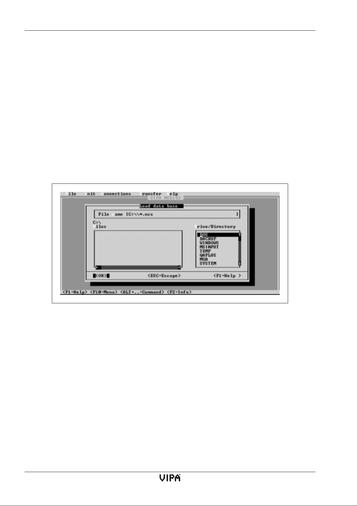
Thebasefile CP143H1 / TCP/IP manual
5.5 The base file
The base file, which is also called the data base file or connection parameter file, contains all the
parameters that may be configured by means of the NCS configuration software. A saved base file
may be transferred into an EPROM or directly to the CP. It is also possible to read an EPROM or a CP
and to save the respective parameters into base file. The default extension of the base file is ".ncs" but
you may change this as desired.
5.5.1 Loading, saving and deleting the base file
Base files may be created/loaded, saved and deleted by means of an interactive window. This
interactive window may be accessed from the menu item File.
Interactive windows show subdirectory entries. You may also select another drive or select files
from this window. In the following paragraph we will explain the operation of interactive windows
by means of the load function. The interactive window may be different, depending on the selected
function, but this does not affect the basic operation.
Fig. 5-2:File selection window by means of the example for Load/Create
This interactive window contains all the elements that are also required for saving and deleting files:
• An input field for direct entry of a file name and path
The field contains the default path + *.ncs. This means that any file with the extension ".ncs"
in the specified directory will be displayed. If you replace the asterisk (*) in the input field
with a complete file name the respective file is loaded. If this file does not exist it will be
created. Your entry is completed when you press the Enter key or when you click on [OK].
• Display field containing the path selected in drive and directories.
• A field to select a drive and a directory.
Select the desired drive and directory by means of a mouse click and press the Enter key. The
path in the display field is updated and all file names with an extension of ".ncs" are
displayed. Click on “..” and press the Enter key to access the next higher level of the directory
tree.
• A field to enter a file name for the selected directory.
Select the required file name and press the Enter key. The selected file will be loaded.
5-6 Rev. 00/07
Page 87

CP143 H1 / TCP/IP manual Software
5.5.2 Printing the base file
You can send the contents of the base file to a text file by means of file/print. This file contains all
initalization data and the configured connections.
This text file has the name of the base file with an extension prn. It is created in the current
directory.
You can use a text processor to open this file and to edit its contents.
Here follows an example of the base file in text form:
VIPA NCS-Projektierung
Initialisierungsparameter
Datum : 06.07.97 Version :
Kachelbasisadresse: 0 Kachelanzahl: 1 (Page frame)
Stationsadresse : 0020d503affe Router1 : 000.000.000.000
IP-Adresse : 000.000.000.000 Router2 : 000.000.000.000
Subnet-Maske : 255.255.000.000 Router3 : 000.000.000.000
Parameter TcpIp
Keep Alive Time : 30000 Window Size : 1024
Large Packets Num : 5 Large Packets Size : 1514
Small Packets Num : 5 Small Packets Size : 160
Timeout Time : 10000
Parameter H1
Min Credit : 0 Retrans Timeout : 100
Persistence Count : 1 Min Retrans Time : 10
Abort Timeout : 6000 Closing Abort Timeout: 600
Protocol Option : 2 Control Win Timeout : 1000
Protocol Class : 4 Inactivity Max Count : 3
TPDU Size : 10 Open Win Timeout : 10
TPDU Additional : 3 Max Open Win Count : 8
Verbindungen (connections)
Verbindungsname L.Tsap/ F.Tsap/ F.Adresse Typ SSNR ANR Prio
Auftragsart Oper DBNr Offs Len Oper DBNr Offs
Port Port
TRANS-Verbindung1 001 001 000000000000 0 1 2 SEND
DATAGRAMM-Verbindung1 002 002 000000000000 EINZEL 0 2 0 SEND
TCP-Verbindung1 00000 00000 000.000.000.000 0 3 2 SEND
UDP-Verbindung1 00000 00000 000.000.000.000 MULTIC 0 4 2 SEND
Fig. 5-3:Sample base file in text form
Rev. 00/07 5-7
Page 88

Thebasefile CP143H1 / TCP/IP manual
5.5.3 Transferring the base file
The NCS provides two options to transfer the base file into the CP:
• by means of an EPROM that you have created using the VIPA-EPROM programmer or the
PG.
• Via the serial interface or the network in remote mode.
The menu item Transfer contains all the functions required for a data transfer between the PC, the
EPROM programmer and the CP.
5.5.3.1 Data base ↔↔↔↔ MC5-EPROM
You can only use the EPROM functions if you have installed a VIPA EPROM programming
adapter into your PC (Order No.: VIPA MC5-KS85). If not, you will receive an error
message!
You may also use the PG to program EPROMs. In this case you can not use the following functions.
The adapter is compatible with the following EPROMs:
• 6ES5 376-0AA11 Memory size 16 KByte NMOS
• 6ES5 376-0AA21 Memory size 32 KByte NMOS
• 6ES5 376-0AA31 Memory size 64 KByte NMOS
• 6ES5 376-1AA11 Memory size 16 KByte CMOS
• 6ES5 376-1AA21 Memory size 32 KByte CMOS
• 6ES5 376-1AA31 Memory size 64 KByte CMOS
For the transfer you may select a base file from one of the following 4 sources:
[Dbase->EPROM]
You will be presented with a file selection window. Select the file for the transfer. Now you
must select the type of EPROM from the module selection window. When you depress the
Enter key the data is transferred to the EPROM.
[EPROM->Dbase]
You will be presented with a file selection window. Enter the file name to which the data
read from the EPROM should be saved.
[NCS->EP]
You will be presented with an EPROM selection window. Select the type of EPROM you
wish to program. When you depress the Enter key the data located in the NCS is
programmed into the EPROM.
[EP->NCS]
You will be presented with an EPROM selection window. Select the type of EPROM you
wish to program. When you depress the Enter key the data is read from the EPROM and
transferred to the NCS configuration program.
5-8 Rev. 00/07
Page 89

CP143 H1 / TCP/IP manual Software
5.5.3.2 Data base ↔↔↔↔ PG-EPROM
You can only use the EPROM functions in conjunction with a PG7xx and the respective
EPROM drivers.
Otherwise you will receive an error message!
The diskette included in the package contains a program RUNNCS.BAT. This program loads the
EPROM driver as a memory resident TSR and starts the configuration program NCS.EXE. When
the configuration program is terminated the driver is removed from memory.
Please start RUNNCS.BAT. If you are working with a PG710 through to a PG740 the driver should
load without errors and NCS should start. In this case you may omit the chapter "Modification of
RUNNCS.BAT".
If you encounter errors the RUNNCS.BAT file must be modified.
Modification of RUNNCS.BAT for a PG7xx
Data base
↔
EPROM can only be executed on a PG7xx if the EPROM driver for the EPROM
programmer was loaded into the PG7xx.
The EPROM driver is delivered with the PG7xx.
The driver consists of a memory resident TSR that must be loaded by means of a LoadHigh
command.
The driver is specific to the PG and it is already located in the PG. The driver is called:
PG710, PG720, PG730 and PG740: SIM_730.EXE
PG750: TRNOSIMA.EXE
You can find the driver by locating the file S5.BAT. This file contains the LoadHigh command for
the driver, e.g. for the PG720:
LH C:\STEP5\S5_ST\SIM_730.EXE IV
Make a note of the respective path and replace the path in RUNNCS.BAT by this new path.
Please be careful!
The file RUNNCS.BAT contains two entries for this path (install and uninstall), i.e. it must
specified twice.
Execute RUNNCS. The EPROM driver will be installed and the NCS program loaded. Now you
may use EPROMs on your PG7xx for configuration purposes.
Your PG is compatible with the following EPROMs:
• 6ES5 376-0AA11 Memory size 16 KByte NMOS
• 6ES5 376-0AA21 Memory size 32 KByte NMOS
• 6ES5 376-0AA31 Memory size 64 KByte NMOS
• 6ES5 376-1AA11 Memory size 16 KByte CMOS
• 6ES5 376-1AA21 Memory size 32 KByte CMOS
• 6ES5 376-1AA31 Memory size 64 KByte CMOS
Rev. 00/07 5-9
Page 90

Thebasefile CP143H1 / TCP/IP manual
Data base ↔↔↔↔ EPROM
When you select Data base
↔
EPROM from Transfer the interactive window "Data
base<>EPROM" will be displayed.
If the program responds with an error message "Eprom-driver not installed!"
the driver could not be installed.
Check the file RUNNCS.BAT for the correct path statement.
You may select a base file from one of the following 4 source / destination combinations for the
transfer:
[Dbase->EP]
You are presented with a file selection window. Select the file for the transfer. Now you
must select the type of EPROM from the module selection window. When you depress the
Enter key the data is programmed into the EPROM.
[EP->Dbase]
You will be presented with a file selection window. Enter the file name to which the data
read from the EPROM should be saved.
[NCS->EP]
You will be presented with an EPROM selection window. Select the type of EPROM you
wish to program. When you depress the Enter key the data located in the NCS is
programmed into the EPROM.
[EP->NCS]
You will be presented with an EPROM selection window. Select the type of EPROM you
wish to program. When you depress the Enter key the data is read from the EPROM and
transferred to the NCS configuration program on your PC.
5-10 Rev. 00/07
Page 91
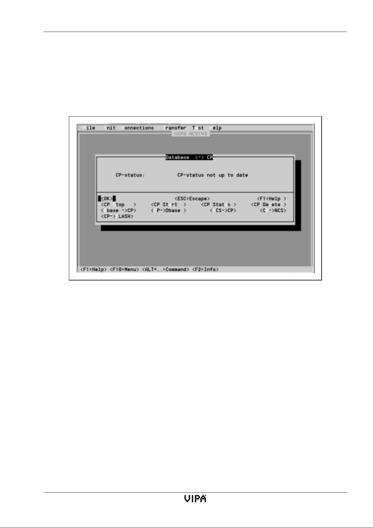
CP143 H1 / TCP/IP manual Software
5.5.3.3 Data base ↔↔↔↔ CP
The remote functions provide the different functions required for remotely controlling the CP
module (start, stop and delete), to request the status from the CP and to transfer data base files into
the CP.
Please make sure that you have specified the online transfer parameters in the section Online (see
chapter 5.6.2).
Remote control of the CP
Switch the RUN/STOP switch on your CP module to RUN. The status display is does not
change automatically when a change of status occurs.
[Stop the CP]
The status of the CP module is changed from RUN to STOP.
[Start the CP]
The status of the CP module is changed from STOP to RUN.
[Delete the CP]
The base file in the CP is deleted. You must first execute a STOP, otherwise the delete
command will be ignored.
CP-status
This output field contains the CP-status. This defaults to the "CP-status not up to date".
Click on [Status] if you wish to display the current status. The displayed status is brought up
to date.
Fig. 5-4: Window for remote configuration
Rev. 00/07 5-11
Page 92

Thebasefile CP143H1 / TCP/IP manual
Transferring the base file
The following points must be noted when base data is transferred between a CP and a PC:
• Communication parameters must have been set in Online.
• A transfer is only possible when the PLC is stopped (STOP status). Please ensure that
your PLC has been STOPped.
• You can only overwrite the data on the CP if the CP does not contain an EPROM.
For the transfer you may select a base file from one of the following 4 source / destination
combinations:
[Dbase→→→→CP]
You are presented with a file selection window. Select the base file for the transfer. This will
be transferred to the CP.
[CP→→→→Dbase]
The data base is located in the CP from where it is transferred to a file. Enter a file name into
the file selection window.
[NCS→→→→CP]
All connections that have been entered into the connection masks of NCS are transferred
directly into the CP.
[CP→→→→NCS]
The data base is located on the CP from where it is transferred directly into the connection
masks of the NCS.
[CP→→→→FLASH]
The data base is located on the CP from where it is transferred directly into a flash-EPROM.
This function is only available from revision level 20 and firmware level V116.
5-12 Rev. 00/07
Page 93
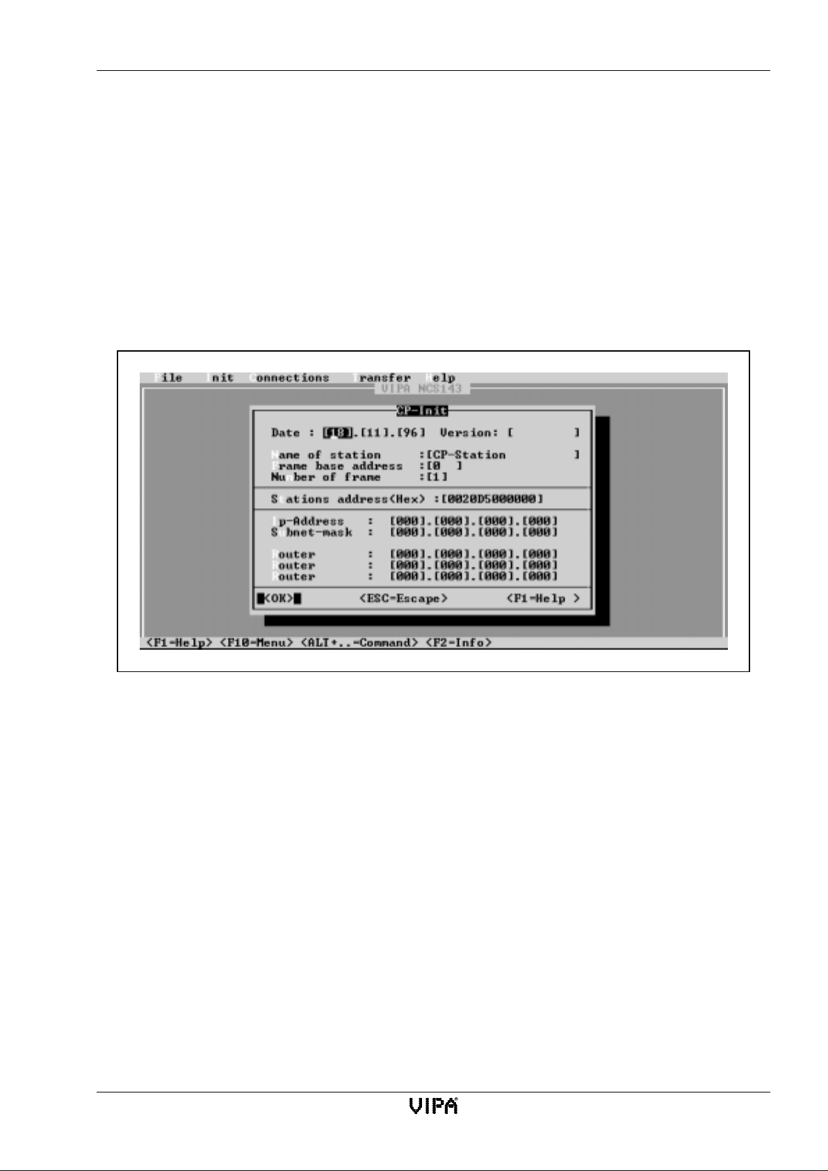
CP143 H1 / TCP/IP manual Software
5.6 Initialization
Every now configuration requires initialization. It is necessary to initialize the identification
parameters as well as H1 and TCP/IP-parameters of the CP143 H1 / TCP/IP-module.
The initialization is not required if you have already loaded a base file. You can find the
initialization functions under menu item Init.
You enter online transfer parameters in the section Online.
5.6.1 CP init
The entry CP-Init under Init places you in an interactive window that provides access to the CPbase initialization:
Fig. 5-5:CP-base initialization (initial initialization)
Here you must configure the addresses and other identification parameters of the CP.
Before entering a connection, you must also enter a frame base address into this interactive mask.
The entered data is transferred when you depress the Enter key.
Parameters of the CP-initialization
Date, Version
The entries for date and version are for documentation purposes only. You can use these
entries to check at what time a configuration was performed. The version number will
always contain the number associated with the file that is currently loaded.
Name of station
You may specify a name for your base station. The name may consist of a maximum of 19
characters. Station names are used to simplify the configuration of connections. The station
name is important where on-line configurations are concerned.
Rev. 00/07 5-13
Page 94
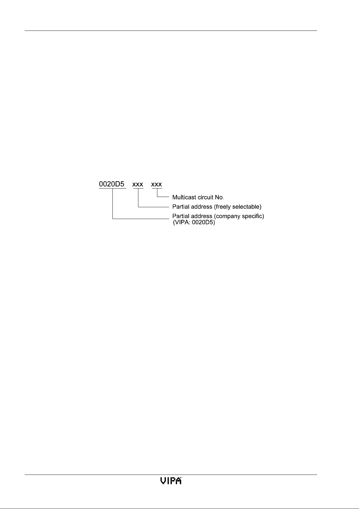
Initialization CP143 H1 / TCP/IP manual
Frame base address
The frame base address Frame base address determines the origin of the frames that are
inserted into the memory area of the controller. The PLC program normally operates on the
base frame. Any other frames may be used by other controller or systems.
The frame base address must be divisible by 4 and it is located between 0 and 255. This
means that you may enter the values 0, 4, 8, 12, ... 252.
The frame base addresses on a single controller may not overlap.
Number of frames
Specifies the number of frames that the CP may use to communicate with the PLC. The CP
always occupies 4 frames (e.g. 4, 5, 6, 7).
Station address
Here you must specify the ethernet address (station address). The structure of the ethernet
addressisasfollows:
IP-address
The IP-address is a 32-bit-address which must be unique within the network. The address
consists of 4 numbers that are separated by a full stop.
Range:000.000.000.000 to 255.255.255.255
You can obtain the IP-address from your system administrator.
Subnet-mask
The IP-subnet-mask is a 32-bit filter mask for IP-addresses. This address is structured in the
same way as the IP-address. It also has the same range.
Subnets allow better control of the addressing area. Subnet-masks should be used where it is
necessary to address a network on both sides of a router although only one network number
is available.
Router
A Router (formerly gateway) can provide a link between different network topologies, e.g.
ethernet to token ring. It may also be used to connect IP-networks with different network
numbers. A router has an IP-address for every network. This IP-address provides the logical
connection between the networks. 2 addresses exist where 2 networks are connected via a
router. If you wish to avoid the use of router-IP-addresses when a connection is established
you may enter 0.0.0.0 for the router.
5-14 Rev. 00/07
Page 95
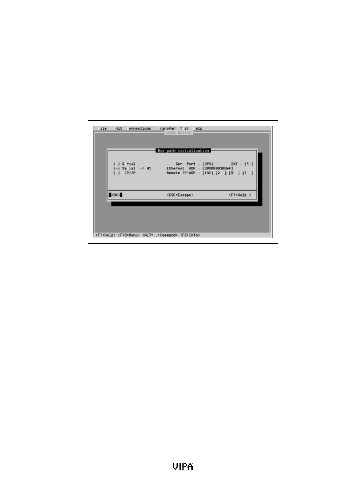
CP143 H1 / TCP/IP manual Software
5.6.2 Online
Online parameters must be specifies when functions are to be used that access the module directly
via the network or via the serial interface. Online functions are only available from firmware level
V110 and an NCS V2.1.
The function database <-> CP under Transfer and die functions under Test make use of online
parameters.
The online dialog window provides access to the following settings:
serial
Data is transferred via the serial COM port of your PC to the PG interface of the
CP143 H1 / TCP/IP. You must specify the port no. and the interrupt.
The following are standard settings:
serial -> H1
Data is transferred via the serial COM port to the PG interface of an H1 module and from
there via the H1 network to a target module identified by means of the respective ethernet
address.
This mode requires specification of the ethernet address of the target module and the serial
parameters (port no. and INT).
TCP/IP
Data is transferred directly via the network to a TCP/IP module. The target module is
specified by means of an IP address.
Fig. 5-6:Parameters for online connections
COM1 = Port 3F8 with INT 4
COM2 = Port 2F8 with INT 3 (default)
COM1 = Port 3E8 with INT 4
Please note!
When using TCP/IP you must enter an ethernet ADR 000000000000h.
Rev. 00/07 5-15
Page 96
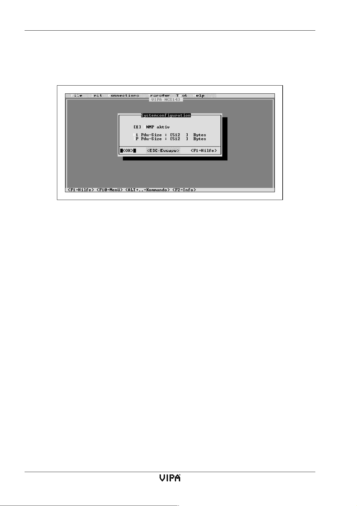
Initialization CP143 H1 / TCP/IP manual
5.6.3 System configuration
When you select system configuration a dialog window containing the general settings for
optimizing t he system performance is displayed.
SNMP active
When this item is selected the Simple Network Management Protocol will be used. SNMP is
normally used for UDP connections.
Default setting: ticked
H1 PDU-Size
Maximum size for H1 data blocks (in byte) that may be transferred via the network level.
PDU is the abbreviation for Protocol Data Unit and refers to a data block.
Range of values: 0...65535, default: 512
IP PDU-Size
Maximum size for IP data blocks (in byte) that may be transferred via the network level.
PDU is the abbreviation for Protocol Data Unit and refers to a data block.
Range of values: 0...65535, default: 512
Fig. 5-7:System configuration parameters
5-16 Rev. 00/07
Page 97
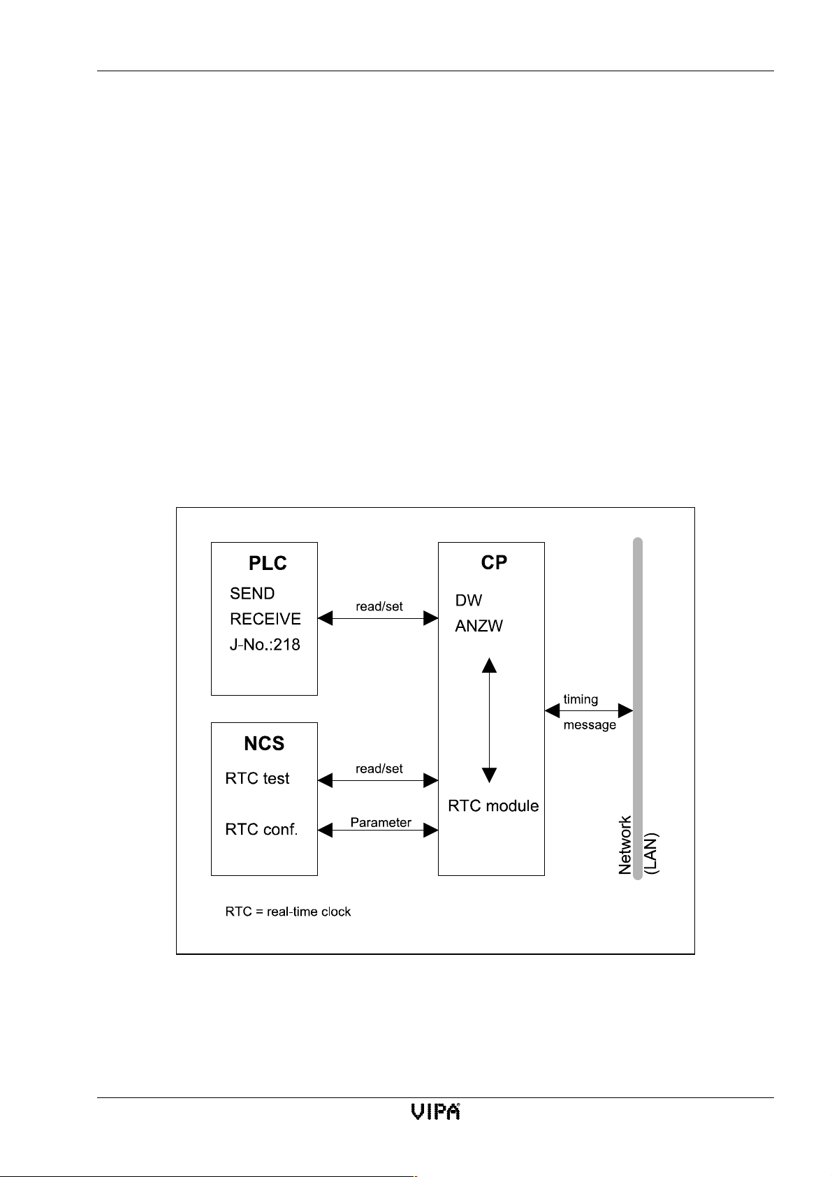
CP143 H1 / TCP/IP manual Software
5.7 Real-time clock functions
5.7.1 General
Many practical situations require that the operations are synchronized and referenced to real time.
The real-time clock functions of the CP143 module may be used to synchronize up to 256 modules
with an accuracy of 10ms. The synchronization is maintained even if the time standard transmitter
should fail.
The real-time clock functions provide the following options
• The time of day is maintained by the system and a battery sustains it should the power supply
fall away.
• The time of the various CPs can be synchronized by means of synchronization messages. In
this way all CPs on the same network use the same time.
• Any CP can be designated as master clock to issue time synchronization messages.
5.7.2 Graphic representation of the real-time clock functions
Fig. 5-8:Graphic representation of the real-time clock functions
Rev. 00/07 5-17
Page 98
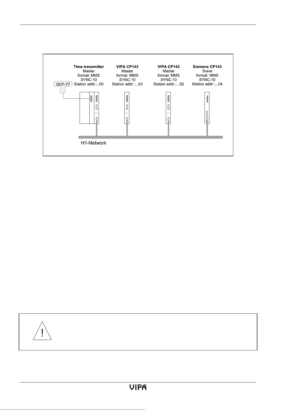
Real-time clock functions CP143 H1 / TCP/IP manual
5.7.3 Construction of a synchronized system:
Fig. 5-9:Construction of a synchronized system
The DCF-77 module receives highly accurate time information and transfers this to the PLC. The
PLC generates a timing message that is transferred via the LAN. This message synchronizes all
CP143 modules connected to the H1-network. The real-time ICs of the different CPs maintain the
time until the next timing message is received.
5.7.4 Mechanism for assigning the master clock
No other CP can become master clock while the time transmission supplies the timing message in
accordance with the SYNC clock.
When timing messages are not received for more than the SYNC cycle time every CP will attempt
to become the master clock in accordance with the priority of its delay time. The priority of the
individual CPs is determined by means of the last byte of the ethernet address. This byte determines
the delay time before the station will attempt to become the master clock. Higher settings for this
value are equivalent to higher delay times before the station will make an attempt to acquire the
master function.
The dynamic master-CP will return to receive mode (slave) if timing messages with a higher priority
are queued or if the DCF-77 becomes active again.
Only modules where the clock init setting was master clock can become a master clock.
The DCF-77 (time transmitter) must always be assigned to the highest
priority, i.e. the last byte of the ethernet address (byte 6) should be 00h.
5-18 Rev. 00/07
Page 99
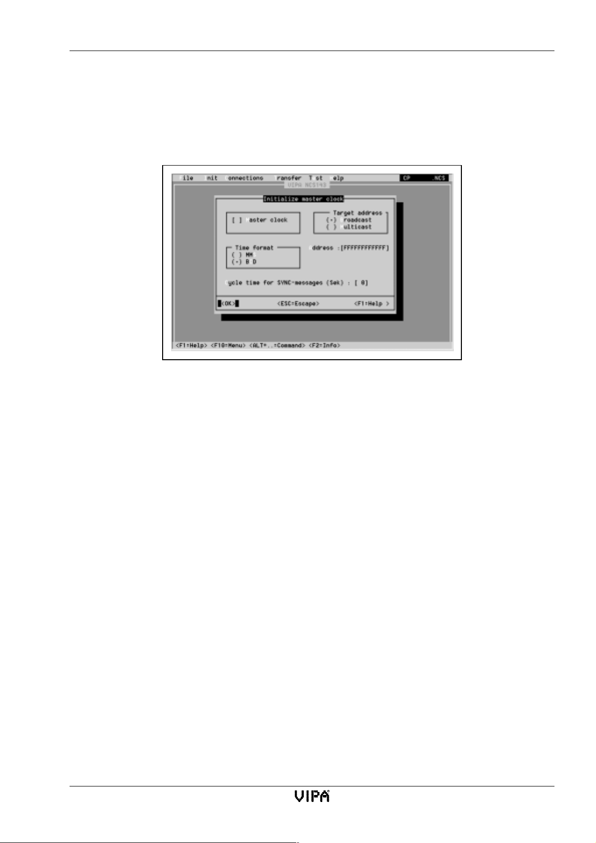
CP143 H1 / TCP/IP manual Software
5.7.5 Master clock initialization
Every CP may assume the role of master provided that it has been configured as a master.
You may mix and match VIPA CPs and Siemens CPs. Please ensure that you use the MMS-timing
format as Siemens supports only this format.
From Init you can use Uhr-Init to access the following initialization window:
Fig. 5-10: Master clock initialization
Parameters for master clock initialization
Master clock
When a high level master clock fails the module configured by means of this parameter may
assume the role of dynamic master. However, the CP can only become the dynamic master if
it has the highest priority and if you have ticked master clock.
master clock: you must supply the target address (broadcast or multicast) and, in the case
of multicast, the target ethernet address and the mandatory time-format and
cycle time.
Slave: enter the mandatory time-format and the cycle time
Target address
Broadcast
Timing messages are sent to every station on the LAN. The address is set automatically to
FFFFFFFFFFFFh. This can not be changed.
Multicast
Timing messages are only sent to stations on the LAN that are a member of the multicast
circuit specified by means of the address.
Address
This address is FFFFFFFFFFFFh when broadcast has been selected. For multicast you must
specify a single address or a multicast circuit by means of the address.
Cycle time for SYNC messages
Here you may determine the cycle time for the transmission of synchronization messages in
the range of 1...60 seconds.
The synchronization message is transferred in MMS- or in BCD format.
Rev. 00/07 5-19
Page 100
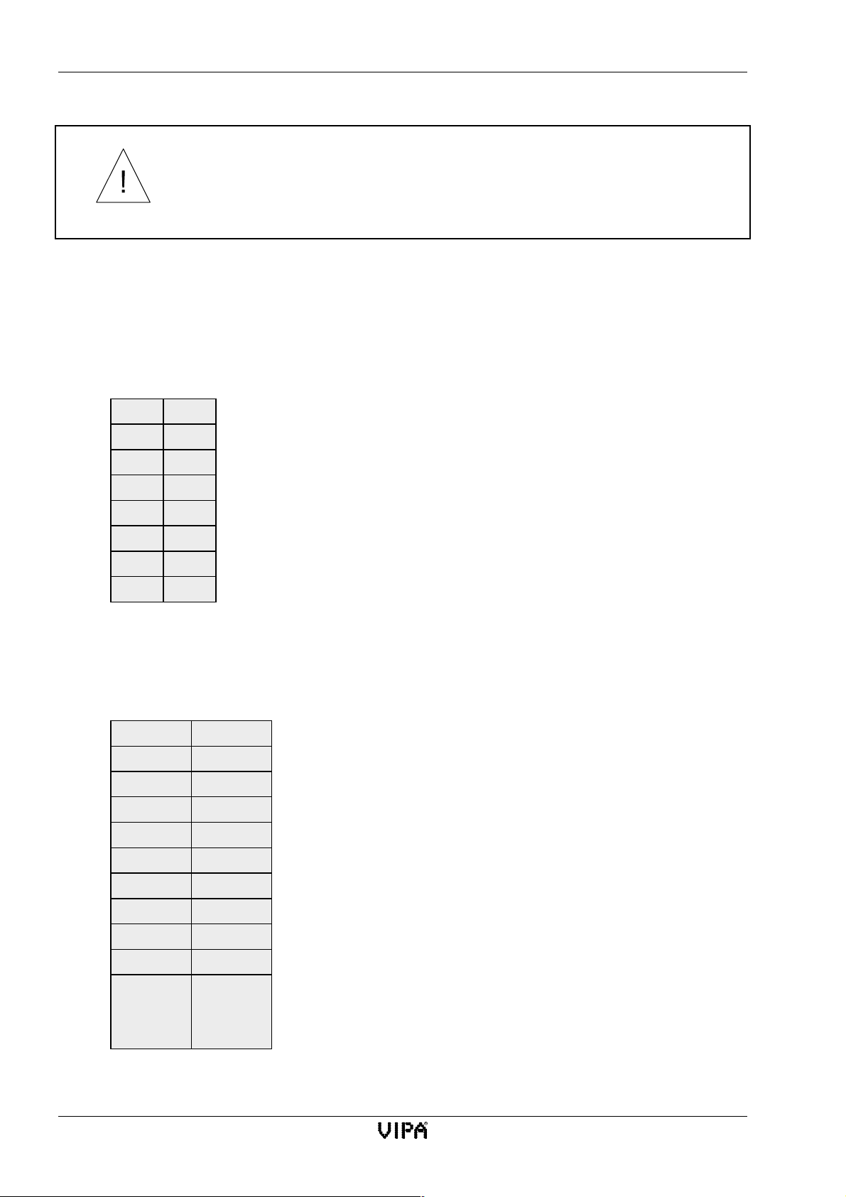
Real-time clock functions CP143 H1 / TCP/IP manual
Please note: the format for the time and the cycle time must be configured in
the same way throughout your system!
The last byte of the ethernet address of each CP must be different!
Time format
MMS format
This is the only format allowed for synchronizing foreign modules. The MMS formatted
timing m essage is formatted as follows:
---- tttt Byte 0 Time in ms, starting from 0:00 hours
tttt tttt Byte 1
tttt tttt Byte 2
tttt tttt Byte 3
dddd dddd Byte 4 Date in days, starting from 1.1.1984
dddd dddd Byte 5
vkkk kk-- Byte 6 Sign v: 0=+, 1=-; time difference steps of in 0,5 hrs.
---- --e- Byte 7 Flag e: 0=time from DCF; 1=from dynamic master
BCD-Format
The BCD format is a plain and readable alternative. If you are only employing VIPA CP143
modules the CPs can be configured to accept BCD formatted messages.
1/10s 1/100s Byte 0 Fractional seconds
10s 1s Byte 1 Seconds
10m 1m Byte 2 Minutes
ab10h 1h Byte 3 Mode a: 0=12h, 1=24h; b: 0=AM, 1=PM; hours
wwww ---- Byte 4 0=Monday ... 6=Sunday
10T 1T Byte 5 Day of Month
10M 1M Byte 6 Month
10J 1J Byte 7 Year
v--k kkkk Byte 8 Sign v: 0=+, 1=-; time difference in steps of 0,5 hours.
---- 1/1000s Byte 9 1/1000s
ssss --em Byte
10
Clock status s: (=clock status in ANZW);
Flag e: 0=time from DCF; 1=time from dynamic master
Module validity m: 0=valid, 1=not valid
The module validity indicates that the current master CP was configured successfully and
that it does not use default parameters.
5-20 Rev. 00/07
 Loading...