

Page 1

Manual VIPA HMI Chapter 1 Hardware description
Chapter 1 Hardware description
Outline
Content
In this chapter the hardware components of the CC 03 are described.
Besides of a description of t he single components, t he dimensions that are
required for the installation of the CC 03 may also be found. The chapter
closes with the technical data.
Please consider the safety hints at the beginning of the chapter.
The following text describes:
• Safety hints
• Control elements and connectors
• Dimensions for installation and technical data
Topic Page
Chapter 1
Safety information for Users.................................................................1-2
Properties.............................................................................................1-4
Structure ..............................................................................................1-5
Dimensions ........................................................................................1-11
CC-CPU - Function security...............................................................1-12
Technical data....................................................................................1-13
Hardware description .....................................................1-1
HB116E - CC03 - Rev. 07/30 1-1
Page 2

Chapter 1 Hardware description Manual VIPA HMI
Safety information for Users
Handling of
electrostatic
sensitive modules
VIPA modules make use of highly integrated components in MOStechnology. These components are extremely sensitive to over-voltages
that can occur during electrostatic discharges.
The following symbol is attached to modules that can be destroyed by
electrostatic discharges:
The symbol is located on the module, the module rack or on packing
material and it indicates the presence of electrostatic sensitive equipment.
It is possible that electrostatic sensitive equipm ent is dest royed by energies
and voltages that are far less than the human threshold of perception.
These voltages can occur where persons do not discharge themselves
before handling electrostatic sensitive modules and they can damage
components thereby, causing the module to become inoperable or
unusable.
Modules that have been damaged by electrostatic discharges may fail after
a temperature change, mechanical shock or changes in the electrical load.
Only the consequent implementation of protection devices and meticulous
attention to the applicable rules and regulat ions for handling the respective
equipment can prevent failures of electrostatic sensitive modules.
Attention!
• Before commissioning, the device has to be brought in environment
temperature.
• With condensation you may only switch on the device after complete
dryness.
• To prevent overheat during operation avoid direct sun contact of the
device.
• After opening of the control cabinet or panel, parts of the system are
available that may lead dangerous voltage.
• All signal connections require screened cables.
• Signal cores may not be lead within a cable shaft of hig h-voltage cores.
• Please take care for suf ficient g round of the operat ing device. For this a
ground screw is to be found at the backside of the device.
1-2 HB116E - CC03 - Rev. 07/30
Page 3

Manual VIPA HMI Chapter 1 Hardware description
Shipping of
electrostatic
sensitive modules
Measurements
and alterations on
electrostatic
sensitive modules
Modules have to be shipped in the original packing material.
When you are conducting measurements on electrostatic sensitive
modules you should take the following precautions:
• Floating instruments must be discharged before use.
• Instruments must be grounded.
Modifying electrostatic sensitive modules you should only use soldering
irons with grounded tips.
Attention!
Personnel and instruments should be grounded when working on
electrostatic sensitive modules.
HB116E - CC03 - Rev. 07/30 1-3
Page 4
Chapter 1 Hardware description Manual VIPA HMI
Properties
General
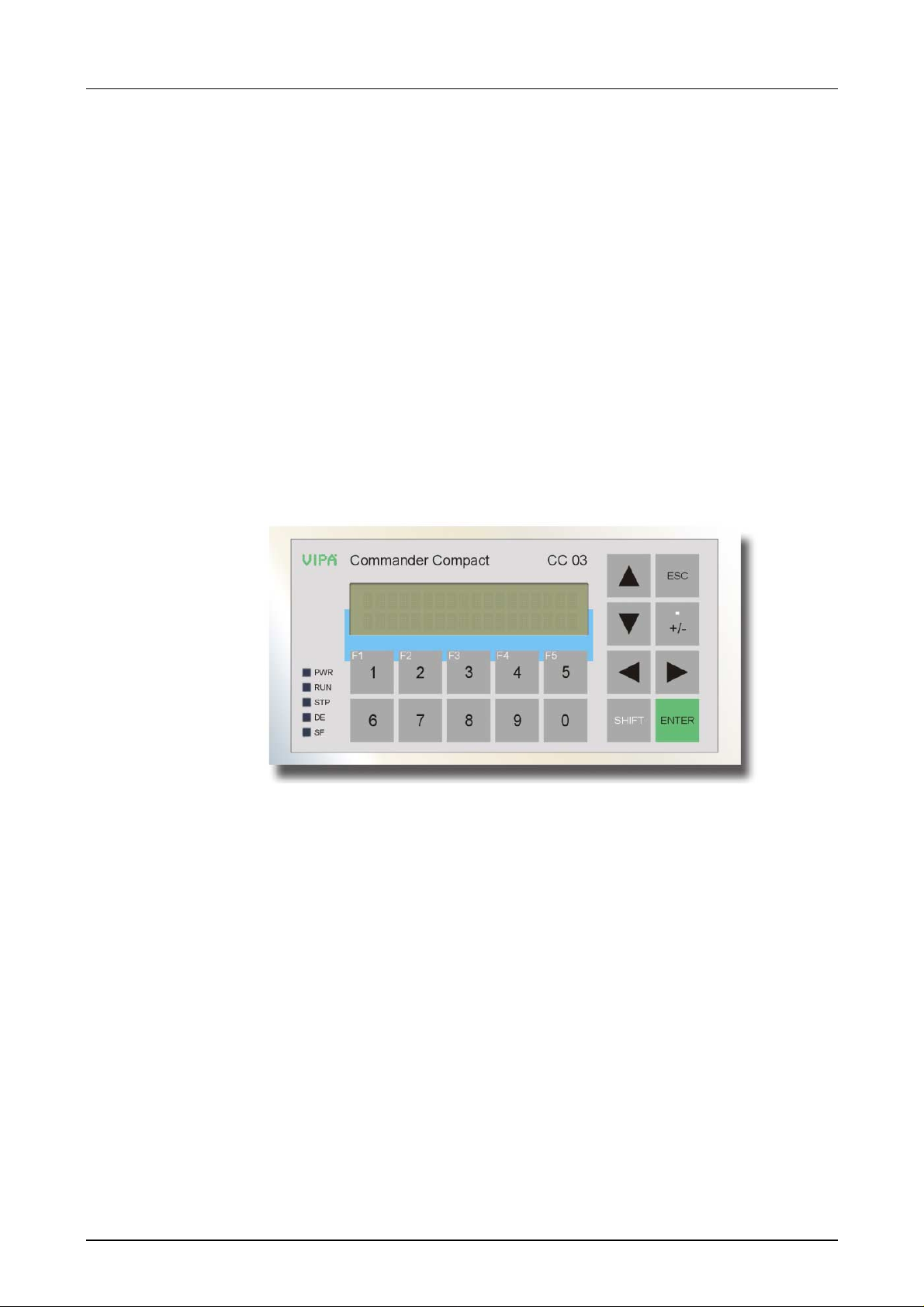
With the CC 03 there is access to the internal CPU. The CC 03 allows you
to monitor and influence operating states and recent process values from
internal CPU. The CC 03 may optionally be connected to the PLC system
as Profibus DP slave (VIPA 603-2CC21).
For the comfor table entry of values and navigation, t he CC 03 is provided
with an integrated keyboard and a 2x20 character display. In addition there
is a PLC-CPU which is programmable by STEP
®
7 from Siemens and an
I/O periphery integrated to the CC 03.
From the software side the connection happens by means of a CC 03
project. The project m ay be created by means of the VIPA OP-Manager or
by ProTool from Siemens. T he project may be transferred from the PC to
the CC 03 by MPI or MMC. During operation, the CC 03 communicates
with the internal CPU and responds to the application processing of the
CPU according to the engineered preset t ing.
Properties
• Display with 2 x 20 characters
• 256kB user memory, 4096 variables
• MP
2
I interface for online proj ect eng ineering , CPU link- up and firmware -
update
• Project engineering via VIPA OP-Manager or Siem ens ProTool
• Menus and input requests in 8 languages
• Read and alter time and counter value
• Monitoring of messages
• Easy installation via non-looseable rocker arms
• Integrated PLC-CPU with status-LEDs on the panel
• 16kB work memory/ 24kB load m em ory
• MMC slot for external MMC storage medium
• Real-time clock
• Integrated I/O periphery
• Expansion option via periphery extension cable
• as VIPA 603-2CC21 optional integrated Pr ofibus DP slave
1-4 HB116E - CC03 - Rev. 07/30
Page 5
Manual VIPA HMI Chapter 1 Hardware description
4
Structure
Front view
Commander Compact
1
2
3
F1 F2 F3
PWR
RUN
STP
DE
SF
1
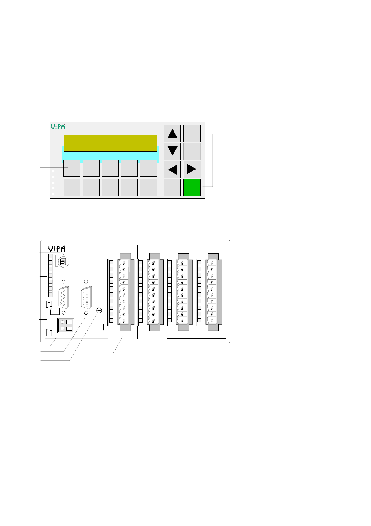
At the front side of the Commander Compact CC 03 are the foil keyboard,
the display with 2x20 characters and the Status LEDs of the CPU.
CC03
ESC
,
+/-
F4
32
F5
4
9876
5
0
SHIFT
ENTER
4
[1] Display
[2] Function keys
[3] LEDs
[4] Navigation keys
Back view
1
R
S
DE
PW
2
SF
FC
MC
3
MMC
X1
+
M
DC24V
5
7
8
RUN
STOP
MRST
M
2
P
I
L+
M
VIPA 603-2CC21
At the CC 03 the connectors are located at back side.
X3
I0
1
2
3
4
5
6
7
8
9
DI 8xDC24V
.0
.1
.2
.3
.4
.5
.6
.7
DI 8xDC24V
.0
.1
.2
.3
D
P
.4
.5
G
.6
.7
X2
34
9
DO 8xDC24V 0,5A
X4
L+
1
.0
2
.1
3
.2
4
.3
5
.4
6
.5
7
.6
8
.7
9
F
I0
DO 8xDC24V 0,5A
X5
L+
1
.0
2
.1
3
.2
4
.3
5
.4
6
.5
7
.6
8
.7
9
F
I0
X6
X2
X3
6
1
2
3
4
5
6
7
8
9
I0
[1] Operating mode switch CPU
[2] LEDs of the CPU part
[3] MP2I slot
[4] Slot for MMC storage
module
[5] Slot for DC 24V power supply
[6] 9pin jack for system bus
extension
[7] RS485 Profibus interface
(only VIPA 603-2CC21)
[8] Ground screw
[9] In-/output periphery
HB116E - CC03 - Rev. 07/30 1-5
Page 6
Chapter 1 Hardware description Manual VIPA HMI
Components
LC-Display
Keyboard
2
I
MP
5
9
4
8
3
7
2
6
1
The CC 03 monitors values and messages via a STN t ext display with LED
back lighting. It displays 2 rows with max. 20 characters with a line height
of 5mm.
At the front side is a foil keyboard with 18 short click keys. 8 keys are
serving the navigation and 10 keys are for num eric input.
The numeric keys F1 ... F5 are configurable as soft key with display
depending functions via the VIPA project engineering tool.
2
The CC 03 is provided with a MP
I (Multi-Point-Interface) for connection to
your CPU via a MPI network and for connection to the PC for project
engineering and firmware update.
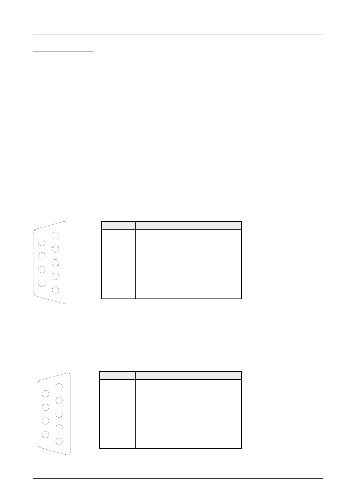
The MPI jack has the following pin assignment :
9pin jack
Pin Assignment
1 reserved (must not be connected)
2 M24V
3 RxD/TxD-P (Line B)
4 RTS
5 M5V
6 P5V
7 P24V
8 RxD/TxD-N (Line A)
9 n.c.
ProfibusDP slave interface
(only 603-2CC21)
Via a 9pin RS485 interface, the CC 03DP is linked-up to Profibus as DP
slave. For project engineering in a Profibus DP master the VIPA GSD file
vipa04dx.gsd is necessary.
The following picture illustrates t he pin assignment of the interface:
9pin jack
Pin Assignment
5
9
4
8
3
7
2
6
1
1 Screen
2 n.c.
3 RxD/TxD-P (Line B)
4 RTS
5 M5V
6 P5V
7 n.c.
8 RxD/TxD-N (Line A)
9 n.c.
1-6 HB116E - CC03 - Rev. 07/30
Page 7
Manual VIPA HMI Chapter 1 Hardware description
Extension jack
Power supply
+
DC24V
L+
M M
Every CC 03 has an integrated 9pin jack at the side. This jack allows you to
extend the CC 03 with up to 4 System 100V expansion modules res.
System 200V modules. Please regard that the maximum current load of
800mA for the backplane bus must not be exceeded.
To connect your modules, a special bus coupling cable is req uired that is
available with order number VIPA 660-0KB00 at VIPA. For the connection,
the bus cable is provided with a 9pin plug at one side and a 1tier bus
coupler at the other. The project engineering of the expansion periphery
happens in the hardware configurator from Siemens.
The CC 03 has an integrated power supply. The power supply has to be
provided with DC 24V (20.4 ... 28.8V). For this an according DC 24V slot is
located at the back side. The power supply is protected against inverse
polarity and overcurrent.
Besides of the electronics, the supply voltage feeds also the optional
components like output periphery, DP slave and bus extension.
Note!
Please regard that the bus extension may stand a max. of 800mA.
LEDs
Operating mode
switch
RUN/STOP/MRST
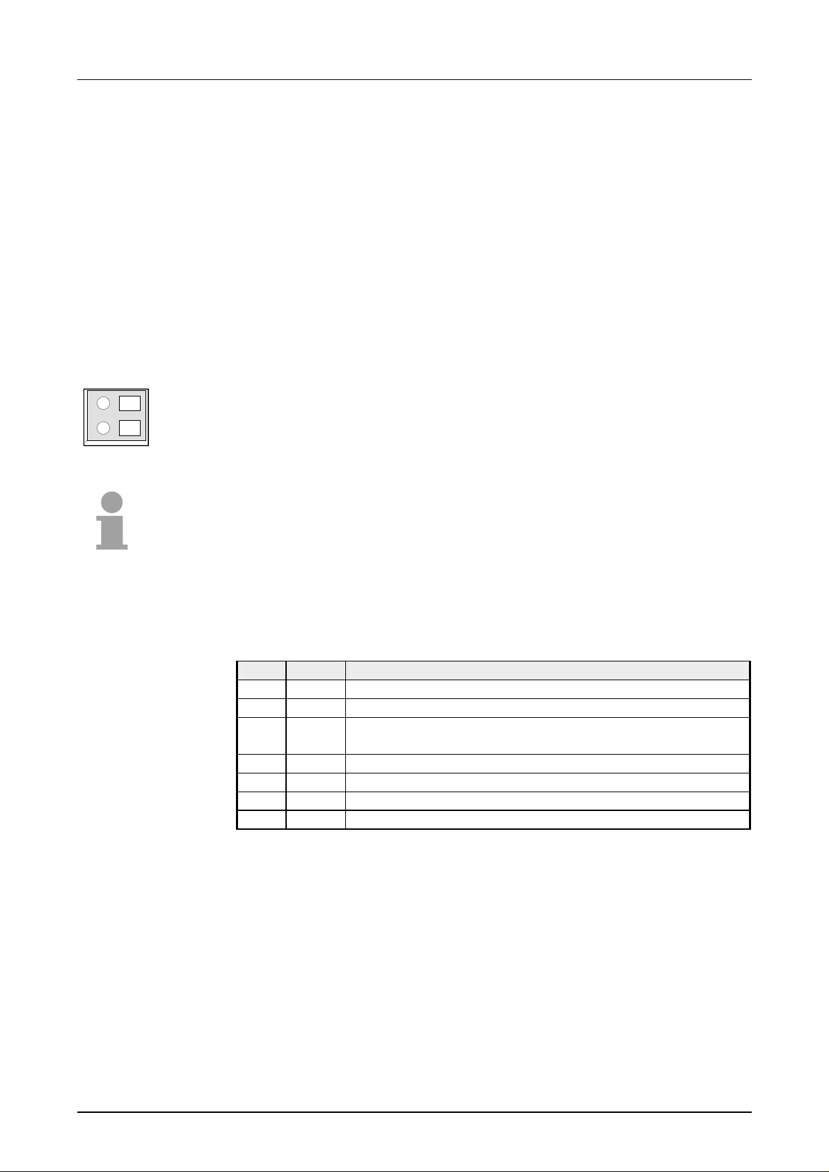
The LEDs at the backside serve the status monitoring of the integrated
CPU and the optional Profibus-DP slave. All LEDs except of FC and MC
are also at the front side. The following table shows color and usage:
Label Color Description
R Green CPU is in the operating mode RUN
S Yellow CPU is in the operating mode STOP
DE Yellow
DE (Data Exchange) indicates Profibus communication
activity of the DP slave. (only VIPA 603-2CC21).
PW Green CPU por tion is supplied internal
SF Red On at system error (hardware failur e)
FC Yellow On as soon as variables are forced*
MC Yellow Shows access to MMC *
* only back side
With the operating mode switch you may choose between the operating
modes STOP and RUN. The operating mode START-UP is processed
automatically by the CPU between STOP and RUN.
By means of the switch location Memory Reset (MRST) you request an
overall reset res. a firmware update from a plugged MMC.
HB116E - CC03 - Rev. 07/30 1-7
Page 8
Chapter 1 Hardware description Manual VIPA HMI
MMC slot
storage module
MC
MMC
X1
Battery buffer for
clock and RAM
+
M
DC24V
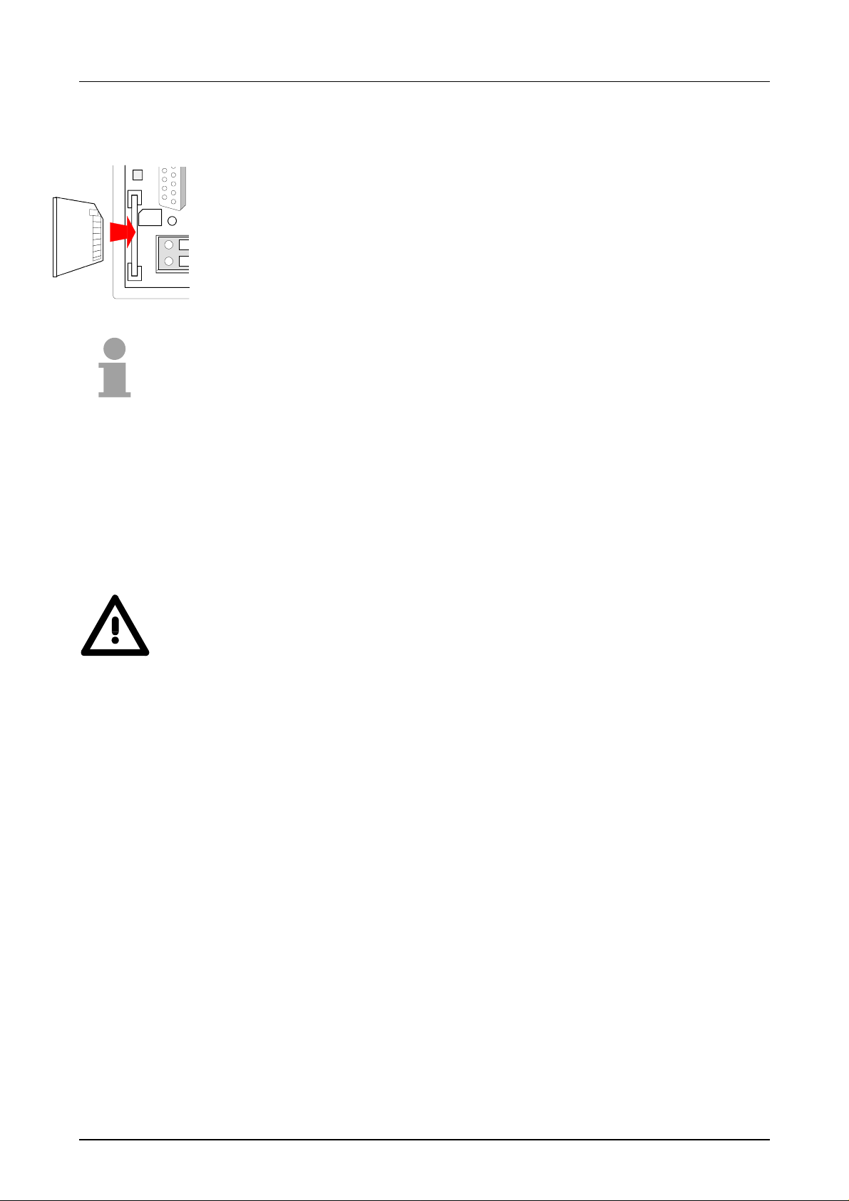
As external storage medium you may plug in a MMC storage module from
VIPA (Order-No.: VIPA 953-0KX10). Access to the MMC always takes
place after an overall reset and af t er PowerON.
Also available at VIPA is an external MMC reading device (Order-No: VIPA
950-0AD00). This allows you to write onto res. read your MMC at the PC.
Please take care at insertion of t he MMC that the flatted part is upside like
shown in the picture.
Note!
Please regard that a write command is f ollowed by an error message when
no MMC is plugged.
Although the data is stored in the internal Flash-ROM.
Every CC-CPU has an internal accu for protecting the RAM at black-out.
Additionally the internal real-time clock is buffered via the accu.
The accu is loaded directly via the integrated power supply by means of
special loading electronics and guarantees a buf fer for max. 30 days.
Internal
Flash-ROM
Attention!
That the CC-CPU is able to switch to RUN, the accu has to be in good
condition.
If there is a defect at the accu, the CC-CPU switches to STOP and
announces a sum error. In this case you should check the CC-CPU. Please
contact VIPA for that pur pose!
Additional to the battery buff ered RAM, the CC-CPU has an internal FlashROM in the size of 24kByte.
Via the writing command PLC > Copy RAM to RO M from the destination
system functions of the hardware configurator fr om Siemens, the contents
of the load memory are transf erred int o the Flash-ROM and simultaneously
to the MMC, if plugged in.
The CC-CPU only accesses the cont ents of the Flash-ROM if the battery
buffered RAM is empty.
The Flash-ROM is not deleted by an overall reset. The Flash- ROM may be
cleared by means of requesting an overall reset and then transferring the
now empty load memory into the Flash-ROM via the PLC function Copy
RAM to ROM.
1-8 HB116E - CC03 - Rev. 07/30
Page 9
Manual VIPA HMI Chapter 1 Hardware description
I/O periphery
DI 16xDC24V
DO 16xDC24V
R
RUN
STOP
S
MRST
DE
PW
SF
FC
M
2
P
I
L+
M
VIPA 603-2CC21
D
P
G
X2
34
MC
MMC
X1
+
M
DC24V
Status monitor
pin assignment
LED
.0... .7
Description
LEDs (green)
I+0.0 to I+0.7
from ca. 15V on the
signal "1" is recognized
and the according LED is
addressed
DI 8xDC24V
.0
.1
.2
.3
.4
.5
.6
.7
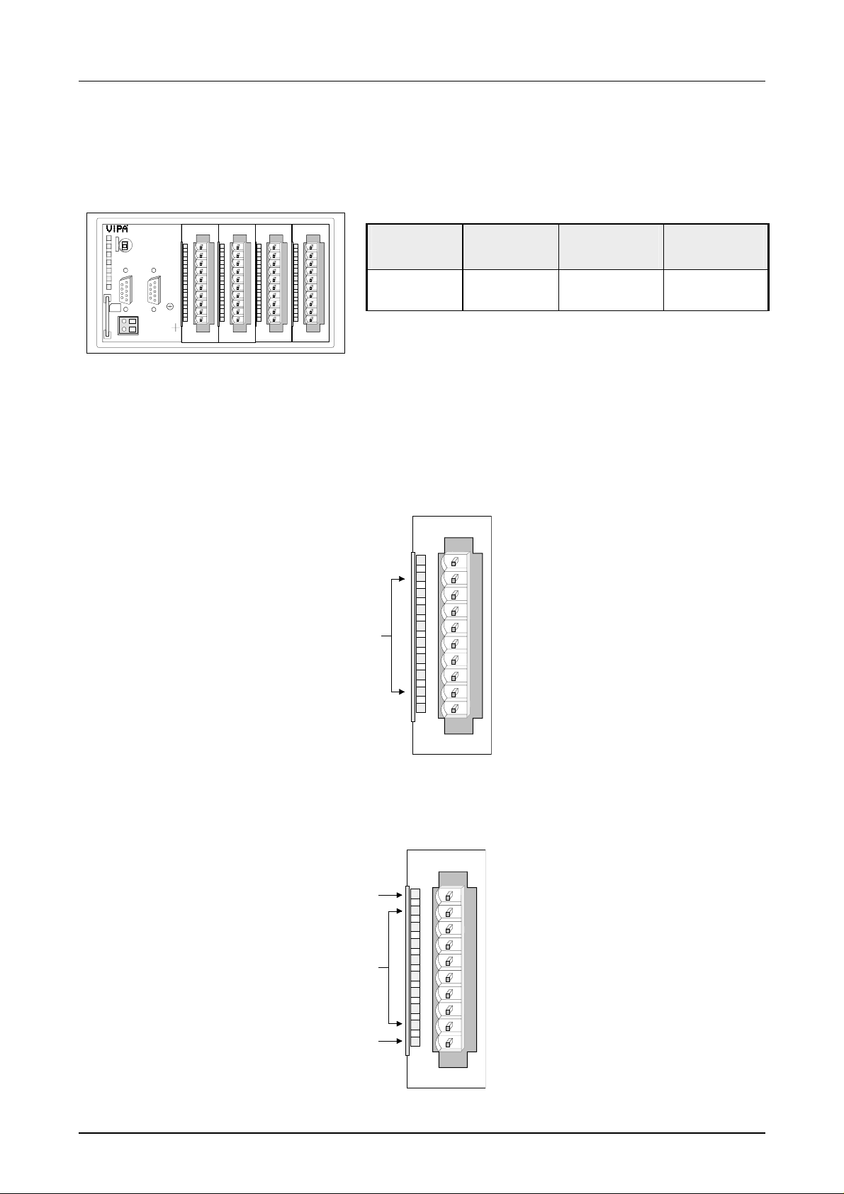
The CC 03 has an integrated I/O periphery which assignment is described
in the following. Please r egard that the output section has to be provided
with external DC 24V!
DI 8xDC24V
X3
X4
1
.0
2
.1
3
.2
4
.3
5
.4
6
.5
7
.6
8
.7
9
I0
DO 8xDC24V 0,5A
L+
1
.0
2
.1
3
.2
4
.3
5
.4
6
.5
7
.6
8
.7
9
F
I0
DO 8xDC24V 0,5A
X5
L+
1
.0
2
.1
3
.2
4
.3
5
.4
6
.5
7
.6
8
.7
9
I0
X6
X2
X3
1
2
3
4
5
6
7
8
9
F
I0
Position 1
X3
DI 8xDC
24V
Position 2
X4
DI 8xDC
24V
Position 3
X5
DO 8xDC
24V 0.5A
Position 4
DO 8xDC
24V 0.5A
Assignment
not used
Input I+0.0
Input I+0.1
Input I+0.2
Input I+0.3
Input I+0.4
Input I+0.5
Input I+0.6
Input I+0.7
Ground
Digital Input
DI 8xDC24V
.0
.1
.2
.3
.4
.5
.6
.7
Pin
1
2
1
2
3
4
5
6
7
8
9
I0
3
4
5
6
7
8
9
10
X6
LED
L+
.0... .7
F
Description
LED (green)
Supply voltage is available
LEDs (green)
Q+0.0 to Q+0.7
as soon as an output is
active, the according LED
is addressed
LED (red)
Error at overload, overheat
or short circuits
Digital Output
DO 8xDC24V 0,5A
L+
.0
.1
.2
.3
.4
.5
.6
.7
F
Pin
1
2
1
2
3
4
5
6
7
8
9
I0
3
4
5
6
7
8
9
10
Assignment
Supply voltage DC 24V
Output Q+0.0
Output Q+0.1
Output Q+0.2
Output Q+0.3
Output Q+0.4
Output Q+0.5
Output Q+0.6
Output Q+0.7
Supply voltage ground
HB116E - CC03 - Rev. 07/30 1-9
Page 10
Chapter 1 Hardware description Manual VIPA HMI
V
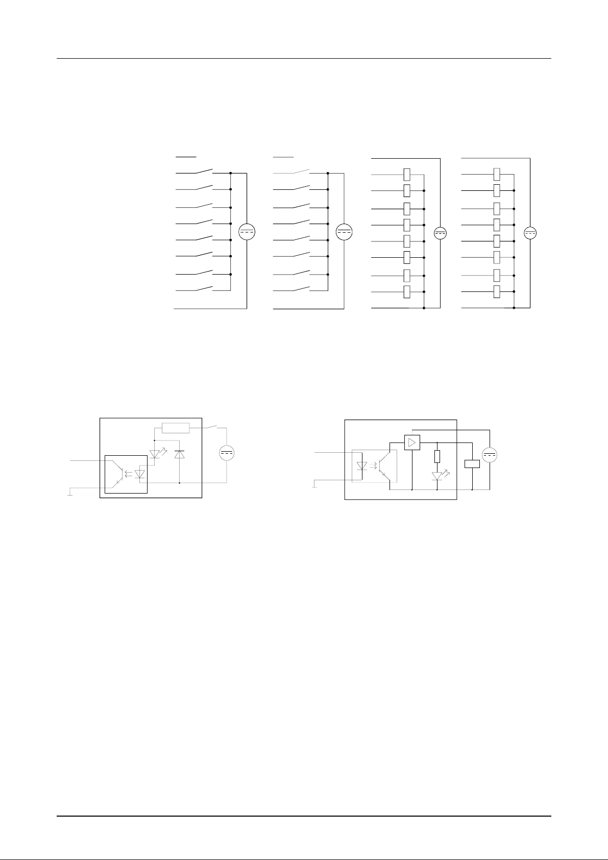
Circuit diagram
Connect the in-/outputs like shown in the picture:
X3
1
2
3
4
5
6
7
8
9
10
M
DC
24V
X4
1
2
3
4
5
6
7
8
9
10
M
Schematic
diagram
Input part Output part
Input
Output
X5
1
2
3
4
5
DC
6
24V
7
8
9
10 M
L+
X6
1
2
3
4
5
DC
6
24V
7
8
9
10 M
L+
DC
24V
V-Bus
Minternal
Opto coupler
LED
DC 24
V-Bus
Minternal
Opto coupler
DC 24V
LED
1-10 HB116E - CC03 - Rev. 07/30
Page 11
Manual VIPA HMI Chapter 1 Hardware description
Dimensions
Installation
dimensions
Top view
Back view
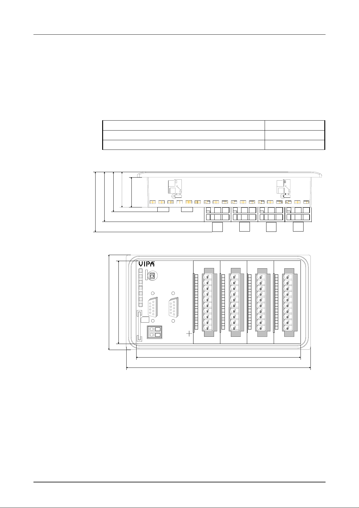
For the installation of the CC 03, an inst allation cutting with the dimensions
156mm x 78mm is required.
Installation values for control cabinets and desk s :
Front panel width: max. 6mm
Installation cutting (W x H): 156mm x 78mm
Installation depth plus cabling 55mm
28
40
34
48
61
90
77
R
S
DE
PW
SF
FC
MC
MMC
X1
L+
M
+
-
RUN
STOP
MRST
M
DC24V
2
P
I
VIPA 603-2CC21
X3
1
2
3
4
5
6
7
8
9
I0
DI 8xDC24V
.0
.1
.2
.3
.4
.5
.6
.7
DI 8xDC24V
.0
.1
.2
.3
X2
34
.4
.5
.6
.7
D
P
DO 8xDC24V 0,5A
X4
L+
1
.0
2
.1
3
.2
4
.3
5
.4
6
.5
7
.6
8
.7
9
F
I0
DO 8xDC24V 0,5A
X5
L+
1
.0
2
.1
3
.2
4
.3
5
.4
6
.5
7
.6
8
.7
9
F
I0
X6
X2
X3
1
2
3
4
5
6
7
8
9
I0
154
187
HB116E - CC03 - Rev. 07/30 1-11
Page 12

Chapter 1 Hardware description Manual VIPA HMI
CC-CPU - Function security
Overview
System properties
Event concerns Effect
RUN → STOP
central digital outputs The outputs are set to 0V.
central analog outputs The voltage supply for the output channels is
decentral outputs The outputs are set to 0V.
decentral inputs The inputs are read constantly from the slave and
STOP → RUN
res. Power on
central analog outputs The behavior of the outputs at restart can be
decentral inputs The inputs are read constantly from the slave and
RUN general The program execution happens cyclically and can
PII: = Process image inputs
PIQ: = Process image outputs
The CPU of the CC 03 includes security mechanisms like a watchdog
(100ms) and a parameterizable cycle time surveillance (parameterizable
min. 1ms) that stop res. execute a RESET at the CPU in case of an error
and set it into a defined STOP st at e.
The VIPA CPUs are developed function secure and have the following
system properties:
general
general First the PII is deleted, the call of the OB100
BASP (Befehls-Ausgabe-Sperre, i.e. command
output lock) is set.
switched off.
the recent values are put at disposal.
follows. After the execution of t he OB, the BASP is
set back and the cycle starts with:
Delete PIQ → Read PII → OB1.
preset.
the recent values are put at disposal.
therefore be foreseen:
Read PII → OB1 → Write PIQ.
1-12 HB116E - CC03 - Rev. 07/30
Page 13
Manual VIPA HMI Chapter 1 Hardware description
Technical data
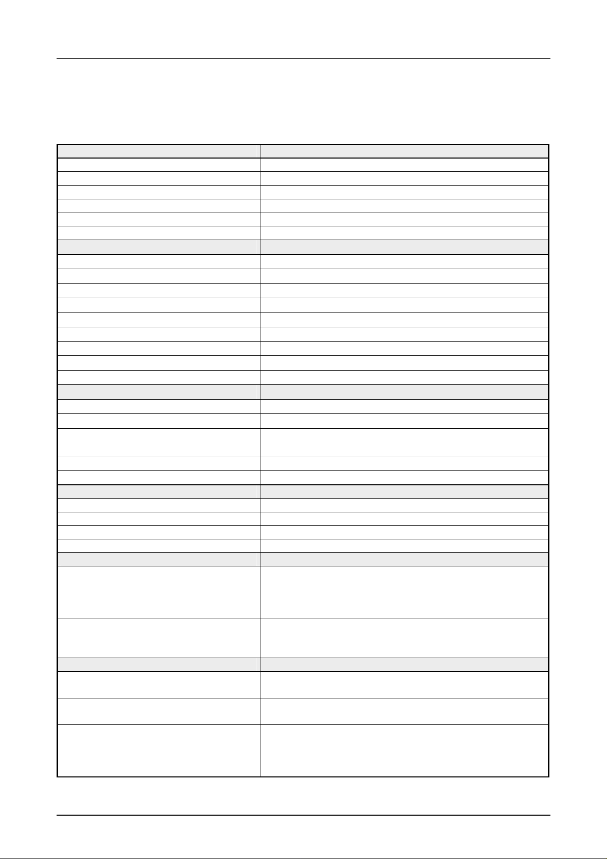
CC 03 - Commander Compact
Electrical data VIPA 603-1CC21 / VIPA 603-2CC21
Nominal supply voltage DC 24V
Current consumption max. 400mA
Max. inrush current
ESD/Burst Acc. IEC 61000-4-2 / IEC 61000-4-4 (up t o level 3)
Shock resistance Acc. IEC 60068-2-6 / IEC 60068-2-27 (1G/12G)
Level of noise suppression Acc. IEC 61000-6-4
Digital input
Number of inputs per column 8
Nominal input voltage DC 24V (18 ... 28.8V)
Signal voltage "0" 0 ... 5V
Signal voltage "1" 15 ... 28.8V
Input filter time delay 3ms
Input current typ. 7mA
Power supply internal
Potential separation 500Veff (Field voltage-backplane bus)
Status monitoring via LEDs at the front side
Digital output
Number of outputs per column 8
Nominal load voltage DC 24V (18 ... 28.8V) via ext. power supply
Current consumption L+ without load
(all Q.x = off) per out put module
Output current per channel 0.5A short circuit resistant
Status monitoring via LEDs at the front side
Memory
Project memory 128kByte (battery buffered RAM)
Variables 4096
W/L m em or y 16/24kByte
External storage medium MMC
Operation panel
Display STN display with LED back lighting
- Number of rows 2
- Character per rows 20
- Character height (mm) 5
Keyboard Foil keyboard with 18 keys
- Number of system keys 8
- Numeric keys and soft keys 10
Interfaces
MP2I 9pin D-type jack at the back side for 1 MPI connection
Profibus-DP (only 603-2CC21) 9pin D-type jack at the back side for Profibus
System extension
- max. current load
3A, 10µs (at 30V)
10mA
res. Serial via Green Cable
communication (9.6kBaud ... 12MBaud)
9pin D-type jack at the back side f or connection of up to
4 System 100V expansion modules res. System 200V
modules
800mA
continued ...
HB116E - CC03 - Rev. 07/30 1-13
Page 14
Chapter 1 Hardware description Manual VIPA HMI
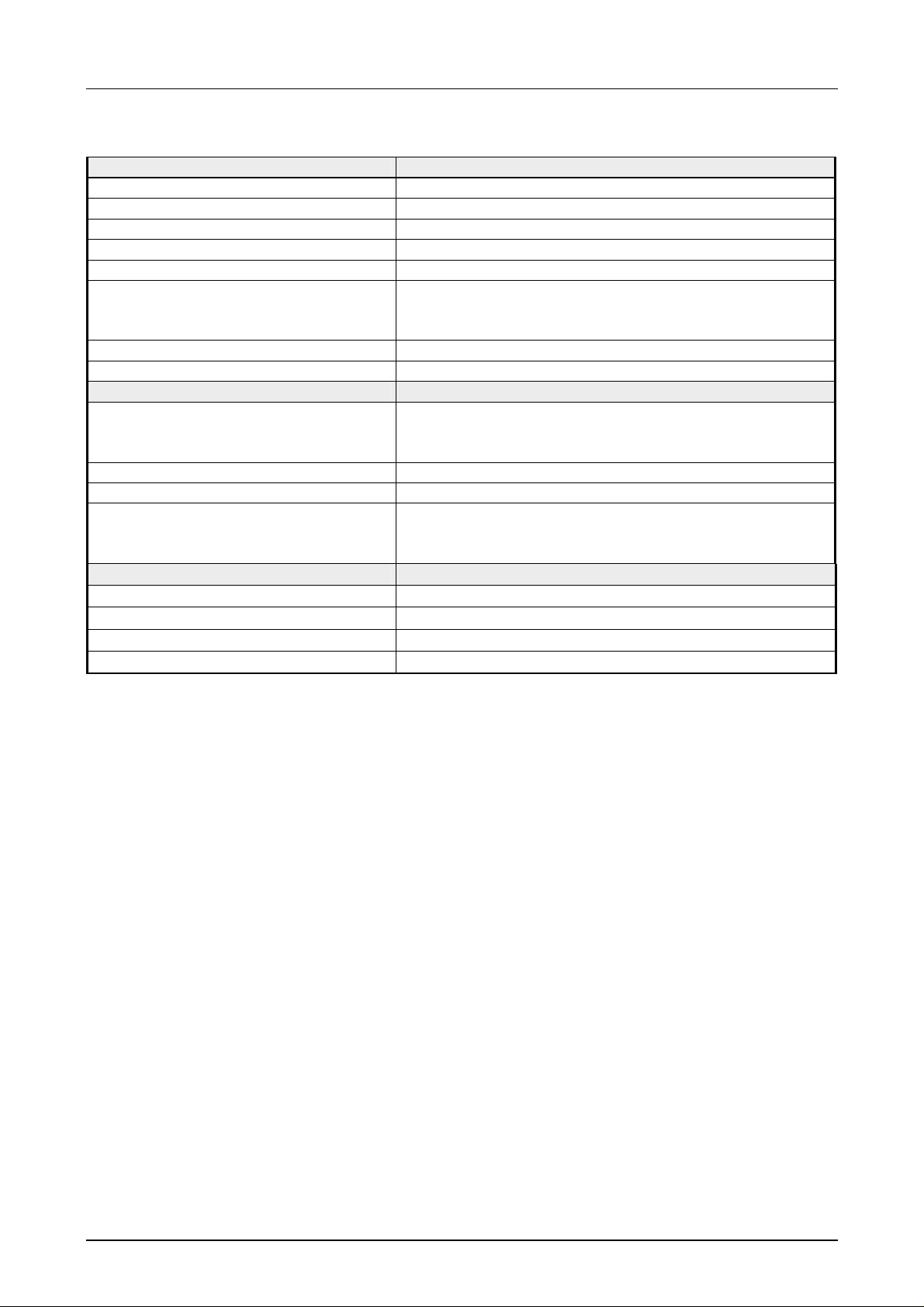
... continue
System data CC-CPU
Work memory/Load memory 16/24k Byte
Clock / Buffer clock and RAM real-time clock / Lithium- Accu, 30 days buffer
Processing time typ. kBit/kWord 0.25/1.2
Marker 8192Bits (M0.0 ... M1023.7)
Timer / Counter 256 (T0 ... T127) / 256 (Z0 ... Z255)
No. of blocks FB
FC
DB
1024 (FB0 ... FB1023)
1024 (FC0 ... FC1023)
2047 (DB1 ... DB2047)
Total addressing space I/Os 256 / 256, from that each 128Byte process image (PA)
PA inputs / PA outputs 1024Bits (I0.0 ... I127.7) / 1024Bits (Q0.0 ... Q127.7)
Environment conditions
Case
- Protect type front side
- Protect type back side
die-cast aluminum case
IP65
IP30
Operating temperatur e 0 ... +60°C
Storage temperature -20 ... +70°C
Relative humidity
- Operation
- Storage/Transport
5% to 85% at 30°C
5% to 93% at 40°C (without condensation)
Dimension and weight
Front side (WxH) 187x90mm
Back side (WxHxD) 154x77x61mm
Installation cutting (WxH) 156x78mm
Weight 610g
1-14 HB116E - CC03 - Rev. 07/30
 Loading...